1
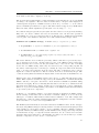
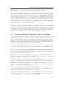
Extending the Kahina
Debugging Environment by a
Feature Workbench for TRALE
Seminar für Sprachwissenschaft
Eberhard Karls Universität Tübingen
Johannes Dellert
Thesis submitted for the degree of
Master of Arts (MA)
Supervisor and first examiner :
PD Dr. Frank Richter
Second examiner :
Prof. Dr. W. Detmar Meurers
Tübingen, February 2012
Hiermit versichere ich, dass ich die vorgelegte Arbeit
selbstständig und nur mit den angegebenen Quellen und
Hilfsmitteln (einschließlich des WWW und anderer elektronischer Quellen) angefertigt habe. Alle Stellen der Arbeit, die ich anderen Werken dem Wortlaut oder dem Sinne nach entnommen habe, sind kenntlich gemacht.
(Johannes Dellert)
Zusammenfassung
Bei der Entwicklung symbolischer Grammatiken für die Verarbeitung natürlicher Sprache
gestaltet sich die Kontrolle der Interaktionen zwischen den implementierten grammatischen
Regeln mit steigender Grammatikgröße zunehmend schwierig. Die vorliegende Arbeit leistet
einen Beitrag zur Erleichterung der Analyse solcher Probleme am Beispiel des TRALESystems, einer Grammatikentwicklungsumgebung, die auf einer getypten Merkmalslogik basiert und vor allem bei der Implementierung von HPSG-Grammatiken zum Einsatz kommt.
Nach einer ausführlichen Besprechung bisheriger Ansätze zur interaktiven Grammatikentwicklung wird zunächst ein neuartiges Modul zur kontextabhängigen Anzeige wichtiger Typeninformationen entwickelt und in Kahina, eine bestehende Umgebung für grafisches Debugging, integriert.
Im zweiten Teil der Arbeit wird die Kahina-Umgebung um eine Workbench für Merkmalsstrukturen erweitert. Das Kernstück dieser Workbench bildet ein grafischer Editor für
Attribut-Wert-Matrizen, der die rasche Manipulation von Merkmalsstrukturen mittels elementarer Operationen erlaubt, welche die für TRALE wichtige Eigenschaft der vollständigen
Wohlgetyptheit erhalten. In der Workbench werden schließlich Operationen auf Merkmalsstrukturen wie Unifikation interaktiv zugänglich gemacht, wodurch wichtige Teilschritte von
Parsingprozessen isoliert durchgeführt werden können. Damit ist die Infrastruktur für eine
deutlich zielgenauere Analyse problematischer Interaktionen geschaffen.
Abstract
When developing symbolic grammars for natural language processing, with growing grammar size it becomes increasingly difficult to maintain control over the interactions between
grammar rules. This thesis strives to develop concepts for facilitating the analysis of such
interactions. The new concepts are implemented as tools for the TRALE system, a development environment for typed feature logic which is mainly used for implementing HPSG
grammars. After an in-depth discussion of previous approaches to interactive grammar development, a novel concept for displaying context-dependent type information is developed
and implemented as a view module for the Kahina graphical debugging environment.
In the second half of the thesis, the Kahina environment is extended by a feature structure
workbench. This workbench is built around a graphical editor for attribute-value matrices
which supports rapid feature structure manipulation by elementary editing operations that
preserve the important property of total well-typedness. In a last step, standard operations
on feature structures such as unification are made available through the workbench in an
interactive fashion, which makes it possible to execute the central steps of parsing processes
in isolation. This functionality allows to analyse problematic interactions in a more finegrained and goal-oriented manner than with previous tools.
iv
Acknowledgements
It is with great relief that I hand in this thesis. It was written in parallel to the preparations
for my final exams in computer science, as a result of my light-headed decision to study
three subjects in parallel. This would not have been possible without the support of many
people, some of which I wish to mention here.
First and foremost, thanks are due to Kilian Evang, who I have had the privilege to work
with for many years. In particular, I fondly remember the many Kahinaden we invested
into designing and implementing the Kahina system. Countless times, it was Kilian who
helped me channel my ambition into useful work, and who prevented me from implementing
daring ideas before thinking them through. He also gave me essential bits of advice for the
implementation, keeping me away from many a blind alley.
Next in the row is Frank Richter, my main teacher of many years, who managed to get me
interested in symbolic approaches right during my first semester, and introduced me to logic
programming, grammar engineering, feature logic, and many other exciting areas of knowledge, during the past six years. He has also been an extremely committed and thoughtful
supervisor during the writing of this thesis. I would also like to express my gratitude to
my other teachers at the Department of Linguistics, especially Dale Gerdemann, Detmar
Meurers, and Fritz Hamm, for their encouragement and many interesting discussions.
I would furthermore like to thank Armin Buch and Kilian Evang for their valuable comments
on a first draft of this thesis. Their feedback helped me a great deal in increasing the clarity
of presentation and in eradicating factual errors. Any remaining errors are mine.
Further thanks go to my fellow students at the Department of Linguistics, many of which
have become good friends, and who created the unique atmosphere of curiosity and openness
that I have been enjoying so much. I am also grateful to my other friends and my family,
who encouraged me to leave my cocoon from time to time, allowing me to partake in their
paths of life and reminding me that a life outside of academia exists.
Finally, I express my deepest gratitude to my wife, Anna. Without her loving care and
unwavering support, I would never have managed to keep up my spirit during the past
stressful years. I am glad that we can now happily look forward to calmer times, knowing
that we can thrive under virtually any circumstances.
Contents
1 Introduction
1
2 TRALE Grammar Development
2.1 Basic Principles and Alternative Approaches . . .
2.2 The Challenges of Symbolic Grammar Engineering
2.3 The Current State of Debugging Technology . . . .
2.4 The Need for Advanced Debugging Tools . . . . .
.
.
.
.
.
.
.
.
.
.
.
.
.
.
.
.
.
.
.
.
.
.
.
.
.
.
.
.
.
.
.
.
.
.
.
.
.
.
.
.
.
.
.
.
.
.
.
.
.
.
.
.
.
.
.
.
.
.
.
.
3
3
5
6
8
3 Kahina and its Predecessors
3.1 Visualization of Parsing Processes in NLP . . . .
3.2 Introducing the Kahina Architecture . . . . . . .
3.3 Visualization and Control Mechanisms in Kahina
3.3.1 Global Views . . . . . . . . . . . . . . . .
3.3.2 Local Views . . . . . . . . . . . . . . . . .
3.3.3 Breakpoint System . . . . . . . . . . . . .
3.4 Discussion . . . . . . . . . . . . . . . . . . . . . .
.
.
.
.
.
.
.
.
.
.
.
.
.
.
.
.
.
.
.
.
.
.
.
.
.
.
.
.
.
.
.
.
.
.
.
.
.
.
.
.
.
.
.
.
.
.
.
.
.
.
.
.
.
.
.
.
.
.
.
.
.
.
.
.
.
.
.
.
.
.
.
.
.
.
.
.
.
.
.
.
.
.
.
.
.
.
.
.
.
.
.
.
.
.
.
.
.
.
.
.
.
.
.
.
.
13
13
17
19
20
21
22
22
.
.
.
.
.
25
25
29
30
31
35
.
.
.
.
.
.
.
.
.
.
37
37
40
41
41
44
46
47
49
53
57
4 Signature Inspection and Visualization
4.1 TRALE Signatures and the Type System . .
4.2 Previous Approaches to Signature Inspection
4.3 Issues in Representing Complex Signatures .
4.4 A Signature Visualization Module for Kahina
4.5 Discussion . . . . . . . . . . . . . . . . . . . .
.
.
.
.
.
5 Signature-Enhanced AVM Editing
5.1 Feature Structures in TRALE . . . . . . . . . .
5.2 Description and Representation Languages . . .
5.2.1 Attribute-Value Matrices . . . . . . . .
5.2.2 TRALE Descriptions . . . . . . . . . . .
5.2.3 The GRISU interchange format . . . . .
5.3 Visualizing Feature Structures . . . . . . . . . .
5.4 Interactive Feature Structure Editing . . . . . .
5.5 Signature-Enhanced Feature Structure Editing
5.6 Implementing the Signature-Enhanced Editor .
5.7 Discussion . . . . . . . . . . . . . . . . . . . . .
vii
.
.
.
.
.
.
.
.
.
.
.
.
.
.
.
.
.
.
.
.
.
.
.
.
.
.
.
.
.
.
.
.
.
.
.
.
.
.
.
.
.
.
.
.
.
.
.
.
.
.
.
.
.
.
.
.
.
.
.
.
.
.
.
.
.
.
.
.
.
.
.
.
.
.
.
.
.
.
.
.
.
.
.
.
.
.
.
.
.
.
.
.
.
.
.
.
.
.
.
.
.
.
.
.
.
.
.
.
.
.
.
.
.
.
.
.
.
.
.
.
.
.
.
.
.
.
.
.
.
.
.
.
.
.
.
.
.
.
.
.
.
.
.
.
.
.
.
.
.
.
.
.
.
.
.
.
.
.
.
.
.
.
.
.
.
.
.
.
.
.
.
.
.
.
.
.
.
.
.
.
.
.
.
.
.
.
.
.
.
.
.
.
.
.
.
.
.
.
.
.
.
.
.
.
.
.
.
.
.
.
.
.
.
.
.
.
.
.
.
.
.
.
.
.
.
.
.
.
.
.
.
.
.
.
.
.
.
.
.
.
.
.
.
.
.
.
.
CONTENTS
6 The
6.1
6.2
6.3
6.4
6.5
6.6
6.7
6.8
6.9
Feature Workbench
Basic Concepts of the Workbench . . . . . . . . . .
Managing an Auxiliary Trale Instance . . . . . . .
Type MGSs and Lexical Entries as Building Blocks
Providing MGS and MGU Computation as Tools .
Composition via Copy and Paste . . . . . . . . . .
The Standalone Feature Workbench . . . . . . . .
Integration with the Kahina-based SLD . . . . . .
Unresolved Issues of the Prototype . . . . . . . . .
Discussion . . . . . . . . . . . . . . . . . . . . . . .
7 Conclusion and Outlook
7.1 Overview of the New Infrastructure . .
7.2 Possible Extensions and Improvements
7.3 Relevance to Grammar Engineering . .
7.4 Future Work . . . . . . . . . . . . . .
.
.
.
.
.
.
.
.
.
.
.
.
.
.
.
.
.
.
.
.
.
.
.
.
.
.
.
.
.
.
.
.
.
.
.
.
.
.
.
.
.
.
.
.
.
.
.
.
.
.
.
.
.
.
.
.
.
.
.
.
.
.
.
.
.
.
.
.
.
.
.
.
.
.
.
.
.
.
.
.
.
.
.
.
.
.
.
.
.
.
.
.
.
.
.
.
.
.
.
.
.
.
.
.
.
.
.
.
.
.
.
.
.
.
.
.
.
.
.
.
.
.
.
.
.
.
.
.
.
.
.
.
.
.
.
.
.
.
.
.
.
.
.
.
.
.
.
.
.
.
.
.
.
.
.
.
.
.
.
.
.
.
.
59
60
61
63
64
68
70
71
72
74
.
.
.
.
.
.
.
.
.
.
.
.
.
.
.
.
.
.
.
.
.
.
.
.
.
.
.
.
.
.
.
.
.
.
.
.
.
.
.
.
.
.
.
.
.
.
.
.
.
.
.
.
.
.
.
.
.
.
.
.
77
77
78
79
80
Bibliography
81
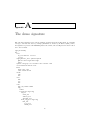
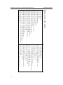
A The demo signature
85
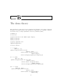
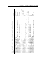
B The demo theory
87
C Overview of relevant Java classes
93
viii
List of Figures
2.1
TRALE’s source-level debugger, embedded in XEmacs. . . . . . . . . . . . . .
3.1
3.2
3.3
A work session using the LKB system. . . . . . . . . . . . . . . . . . . . . . . 14
Architecture of the Kahina-based TRALE debugger. . . . . . . . . . . . . . . 18
A session of the Kahina-based TRALE debugger. . . . . . . . . . . . . . . . . 20
4.1
4.2
4.3
4.4
4.5
4.6
4.7
4.8
Demo signature from Appendix A, in formal notation. . . . . . . . .
Demo signature from Appendix A, visualized as a graph. . . . . . . .
LKB type hierarchy view, context menu providing various options. .
Using MoMo to explore the demo signature. . . . . . . . . . . . . . .
Kibiger’s signature visualization. . . . . . . . . . . . . . . . . . . . .
Hierarchy view component displaying information on the type index.
Appropriateness and type usage view components. . . . . . . . . . .
Default configuration of signature view with info on type word. . . .
.
.
.
.
.
.
.
.
.
.
.
.
.
.
.
.
.
.
.
.
.
.
.
.
.
.
.
.
.
.
.
.
.
.
.
.
.
.
.
.
27
28
30
31
32
34
35
35
5.1
5.2
5.3
5.4
5.5
5.6
5.7
5.8
The lexical entry for walks in formal notation, and as an AVM.
A description whose MGS is our lexical entry for walks. . . . .
The lexical entry for walks in GRISU format . . . . . . . . . .
LKB feature structure visualization with context options. . . .
Architecture of the signature-enhanced editor. . . . . . . . . . .
Specializing a cont object to a nom obj. . . . . . . . . . . . . .
Dissolving an identity. . . . . . . . . . . . . . . . . . . . . . . .
Second step of an identity introduction. . . . . . . . . . . . . .
.
.
.
.
.
.
.
.
.
.
.
.
.
.
.
.
.
.
.
.
.
.
.
.
.
.
.
.
.
.
.
.
.
.
.
.
.
.
.
.
42
44
46
48
54
55
55
56
6.1
6.2
6.3
6.4
6.5
6.6
6.7
6.8
Workbench prototype with embedded signature-enhanced editor. . . .
Example of the hierarchical menu for type selection. . . . . . . . . . .
Architecture for retrieving lexical entries. . . . . . . . . . . . . . . . .
Architecture for theory-based MGS computation. . . . . . . . . . . . .
Executing the theory MGS operation on the type MGS of phrase. . .
Architecture for theory unification. . . . . . . . . . . . . . . . . . . . .
The input structures for the unification example. . . . . . . . . . . . .
Comparison of the signature MGU (left) and the theory MGU (right).
.
.
.
.
.
.
.
.
.
.
.
.
.
.
.
.
.
.
.
.
.
.
.
.
.
.
.
.
.
.
.
.
62
65
65
66
67
68
68
69
ix
.
.
.
.
.
.
.
.
.
.
.
.
.
.
.
.
.
.
.
.
.
.
.
.
9
Chapter
1
Introduction
Current approaches to automated processing of natural language syntax and semantics almost exclusively rely on shallow statistical methods, which have proven to be superior to
previous methods on noisy real-life data, especially if performance is taken into account.
This trend has led to a deep divide between the methods commonly used in computational
linguistics, and the methods of linguistics proper. The deep insights of linguistic theories
are considered to be of little use for real-life applications, whereas the tools created by computational linguists become increasingly less interesting to linguists.
This trend has resulted in perils for both sides. Linguists develop elaborate theories on
paper, which cover important generalizations and are of central importance for furthering
our understanding of language, but they cannot evaluate these theories on a wider range of
structures because of a lack of computational tools which would allow them to be intuitively
implemented and tested.
On the other hand, modern computational tools for processing natural language almost exclusively rely on surface patterns, which works reasonably well for simple tasks, but does
not have much potential for deeper levels of analysis. In particular, integrating linguistic
knowledge into such systems is very difficult.
More traditional rule-based methods are clearly more useful for implementing and evaluating
linguistic theories, and they make it possible to keep up the goal of deep analysis. However,
apart from their weakness in coverage, such symbolic grammars are also very difficult to
design. These difficulties are not only caused by the multitude of structures, but also by
the notorious tendency of hand-written grammars to get out of hands when attempting to
cover a reasonably wide range of linguistic phenomena occurring in natural input.
The chief cause of this are the heavy interactions between rules which tend to grow very
quickly with grammar size, and which need to be carefully controlled. This slows down the
writing of larger grammars considerably, at some point making it virtually impossible to
keep track of all the interactions.
As part of a larger effort to alleviate these difficulties, this thesis introduces some new concepts and tools for making rule interactions more transparent in grammar formalisms based
on typed feature structures. This work partially builds on ideas developed for older grammar
development environments, mainly during the last burst of work in that area about fifteen
years ago.
1
EXTENDING KAHINA BY A FEATURE WORKBENCH
JOHANNES DELLERT
The test case for these concepts is the development of grammars in the TRALE system,
a leading platform for implementing grammars in the framework of HPSG (Head-Driven
Phrase Structure Grammar).
In Chapter 2, I give a quick overview of the TRALE environment, and discuss the main
issues of grammar development in that system. I then discuss the current state of grammar
debugging tools for TRALE, explaining why new advanced debugging methods are desirable
for novice and veteran grammar engineers alike.
Chapter 3 gives a short historical overview of advanced tools for grammar engineering, which
are mainly evaluated with respect to their methods for visualizing the internals of parsing
processes and for exposing central operations to the grammar engineer as interactive tools.
In the second half of the chapter, I introduce the Kahina debugging environment which
serves as the basis for this work.
Chapter 4 discusses existing tools for signature inspection and visualization, leading to a
novel HTML-based signature information system inspired by Javadoc, the leading tool for
the documentation of Java classes. At the end of the chapter, I present and discuss an
implementation of these ideas as a new Kahina component.
Chapter 5 introduces signature-enhanced AVM (Attribute-Value Matrix) editing as a comfortable way of manually constructing feature structures that can later be used for interactively exploring rule interactions. A set of elementary editing operations is formally developed to the degree that can be implemented. The implementation of these operations
results in an editing system that allows the user to freely manipulate parts of feature structures in a point-and-click-fashion while the editing system is responsible for ensuring that
the resulting structures always adhere to a signature.
In Chapter 6, the new tools from the previous chapters are integrated into a feature workbench, which exposes important parts of the TRALE parsing process to the user in an
interactive fashion. The main design decisions are motivated, focusing on the architectural
problems that had to be overcome. The chapter concludes with a discussion of problems
and possible extensions to the feature workbench.
Chapter 7 summarizes the main results of the thesis and puts potential usage scenarios for
the workbench into a broader context of next-generation grammar engineering.
The appendices contain the source code for the TRALE demo grammar which is used
throughout this thesis, and a list of the relevant new interfaces in the Kahina system. The
full names of the Java classes mentioned in the text can also be found there.
The ideal reader of this thesis knows the basics of HPSG, has some experience with grammar engineering in a unification-based grammar formalism, and possesses some familiarity
with the programming languages Java and Prolog. Experience with the TRALE system is
not strictly necessary, but will certainly be helpful for fully understanding the scope and
motivation of this work.
2
Chapter
2
TRALE Grammar Development
In this chapter, I give an overview of the TRALE system that serves as a basis for all the
software components which are developed and discussed in this thesis. Section 1 starts with
a list of TRALE’s features for implementing HPSG grammars, and continues with a comparison to the LKB as the other major platform used for this purpose. Section 2 continues
with the challenges of large-scale symbolic grammar engineering in general, elaborating on
the key conflict between the generality and the modularity of grammar implementations,
and explaining the potential role of debugging technology in remedying these issues. This
leads to an in-depth discussion of TRALE’s current debugging mechanisms in Section 3, and
of the potential benefits of more advanced (graphical) debugging tools in Section 4.
2.1
Basic Principles and Alternative Approaches
The TRALE system is a substantial extension to the Attribute Logic Engine (ALE) as
described by Carpenter and Penn (1999). It was developed with the goal of facilitating
the direct implementation of HPSG grammars in a format that appeals to linguists. The
development of TRALE began in the context of the SFB 340 and was continued as part of
the MiLCA project (see Meurers et al., 2002). The system has been the subject of continual
evolution since then. The most recent (yet somewhat outdated) documentation of TRALE
can be found in Penn et al. (2003).
A TRALE grammar consists of a signature and a theory. The signature is a type hierarchy
which licenses a set of possible feature structures, expressing some general restrictions on
their structure. The theory then defines further (implicational) constraints on the structures licensed by a signature. This separation closely mirrors the structure of an HPSG
grammar, where the signature is used to define possible signs such as words and phrases
represented by feature structures, and the theory is used to express rules and principles of
grammar, e.g. the Head Feature Principle.
TRALE’s type system implements exhaustive typing, a principle formalizing an assumption implicit in typical HPSG grammars (such as that of Pollard and Sag (1994)). Exhaustive
typing states that objects of a non-maximal type must simultaneously be of one of the subtypes. For instance, there are no signs that are not either phrases or words.
The TRALE constraint language makes it possible to freely define implicational constraints
on feature structures, and it offers a formalism for description-level lexical rules (DLRs)
whose behavior comes very close to the intuitions behind hand-written rules in the format
3
EXTENDING KAHINA BY A FEATURE WORKBENCH
JOHANNES DELLERT
commonly used in the HPSG literature.
The description language is enhanced by a Prolog-style programming language for definite
relations, allowing commonly used relations such as append/3 to be used for expressing
type constraints and rules, and a powerful macro mechanism that is especially useful for
defining a large lexicon where many entries have common properties.
For efficiency reasons, a TRALE grammar is based on a context-free skeleton defined by
phrase-structure rules, The categories in these rules are terms of an attribute-value description language, and definite clause goals can be attached to the rules in analogy with
Prolog’s in-built DCG mechanism.
Taken together, these features permit a rather direct and natural implementation of typical
HPSG grammars, although the learning curve especially for users with limited programming
experience can be steep, and the powerful formalism leads to efficiency issues that require
efficient implementation strategies.
The second leading platform for the implementation of HPSG grammars is the Linguistic
Knowledge Building (LKB) system. Just like the ALE system underlying TRALE, the
LKB is designed as a framework-independent platform for unification-based grammars, although it is most commonly used for type feature structure formalisms such as HPSG.
The LKB has been under development and in use for two decades, most prominently as the
primary development platform for the broad-coverage LinGo English Resource Grammar
(ERG), as presented in Copestake and Flickinger (2000). Copestake (2002) is the primary
documentation for more recent versions of the LKB.
Unlike TRALE, the LKB centralizes all the type information, including all the constraints,
in just one file. TRALE enforces some technical constraints on the definable type hierarchies, whereas the LKB takes the liberty of automatically restructuring the types defined by
the grammar writer into a more complex hierarchy that fulfills the very same constraints.
The LKB can therefore accept a liberal format for type definitions that seems more userfriendly at first sight, but can lead to confusion about the types that are then used internally.
TRALE forces the user to think harder about the signature, but then displays computational
behavior that is closer to the specification.
Because in the LKB, all constraints must be stated as part of type definitions, they always
apply to structures of one specific type. TRALE offers more expressive power by allowing
feature structures as complex antecedents in its implicational constraints. This makes it
possible to single out classes of linguistics objects that do not correspond to a type, whereas
the LKB forces the user to introduce a type distinction even if the corresponding class of
objects is only relevant in the context of a single rule.
The LKB clearly lags behind TRALE in faithfulness of implementation for typical grammars developed by linguists. The gap between linguistic theory and the implementation is
rather wide, whereas TRALE’s advanced features allow grammar implementations to stay
notationally and conceptually close to what linguists are used to developing on paper.
But not only for novices in grammar implementation, these disadvantages are compensated
for by the fact that the LKB features a window-based graphical interface for user interaction that is chiefly operated using the mouse, whereas TRALE is based on command-style
interaction with a Prolog prompt.
4
CHAPTER 2. TRALE GRAMMAR DEVELOPMENT
For larger grammar implementations, sophisticated test suite facilities are indispensable.
Both TRALE and the LKB offer an interface to the [incr tsdb()] package by Oepen (2001)
for batch parsing. This package can be used to maintain annotated databases of test and
reference data, to browse these databases in order to compose suitable test suites, and, most
importantly, to collect fine-grained profiling data for evaluating system performance. Such
data are very useful for identifying inefficient parts of a grammar implementation.
In a thorough comparison of the two platforms from a grammar writer’s point of view,
Melnik (2007) considers the graphical user interface to be the core advantage of the LKB
over TRALE, especially in the eyes of a not very computer-savvy linguist. Developing an
interface for TRALE with comparable characteristics has therefore been the main motivation
for the work leading up to this thesis, and the LKB system has been an important source
of inspiration.
2.2
The Challenges of Symbolic Grammar Engineering
One of the reasons why rule-based approaches to NLP have suffered a steep decline in
popularity is that these approaches failed to include statistical information, leading to low
coverage and severe problems with disambiguation. Whereas combinations of rule-based
and data-driven models can improve this situation a little, another weakness of symbolic
grammar engineering is a lot more difficult to address. Rule-based grammar development
traditionally relies on the expert knowledge of an experienced grammar engineer, who needs
intimate knowledge of all the grammar components to assess the consequences of modifications. As a grammar grows, the rule interactions become increasingly hard to understand
and control, slowing down development considerably. These difficulties are aggravated by
the fact that for large-coverage grammars, it is indispensable that multiple persons contribute to grammar development.
From a theorist’s point of view, a grammar is only attractive if it expresses all known generalizations on as many levels as possible. The generality of the principles developed in this
tradition quickly leads to a situation where rules and constraints are heavily interdependent,
leading to all kinds of interactions that a grammar writer must take care of when making
even the slightest modification.
Keeping track of such rule interactions is difficult even for the very restricted problem
domains usually modeled by theoretical linguists. The interactions between various such insular theories are seldom discussed in the literature, and if they are, the arguments are often
rather informal. If one tries to bring such insular solutions together in an implementation,
undesired interactions between such theories, which tend to be formulated in as general a
fashion as possible in their respective insular context, regularly lead to problems.
From an implementer’s point of view, the core problem of linguistic theories can be identified
as a lack of modularity. One of the hard lessons learnt in software engineering is that a lack
of modularity leads to difficulties in extensibility. Unsurprisingly, these difficulties also turn
up in grammar engineering.
For the case of HPSG, Moshier (1997) gives an impressive account of such difficulties. For
instance, even a simple principle such as the Head Feature Principle occurs in various incompatible versions in the literature, usually adapted in an ad-hoc manner to block unwanted
interactions with a newly developed insular theory.
In an attempt to improve the modularity of HPSG, Moshier fleshes out a strict formalization
of HPSG grammars that is based on category theory and strives to abstract away from what
5
EXTENDING KAHINA BY A FEATURE WORKBENCH
JOHANNES DELLERT
he calls the feature geometry of a concrete implementation. This would allow principles
to be stated independently, and would force the grammar writer to explicitly control the
interactions. Unfortunately, later experience has shown that linguists tend to dislike formal
constraints that have good mathematical properties, but cannot be independently motivated
on linguistic or cognitive grounds, and detract from their freedom in using a powerful formalism to express generalizations naturally.
To increase modularity, an experienced programmer would want to refactor the grammar
according to principles of sound software engineering. Unfortunately, such a refactoring will
inevitably destroy many of the generalizations that a linguist would want to see expressed.
In grammar engineering, modularity and generality are therefore conflicting goals.
This means that the rule interaction problem is inherent in the grammar engineering task,
and cannot be avoided by the use of sophisticated tools. In order to help symbolic grammar
engineering deal with these difficulties, one can only develop and provide useful methods for
analysing and understanding the interactions more easily. This requires tools which make
the interactions more transparent to the grammar implementer, and which provide quick
access to explanations for undesired behavior.
2.3
The Current State of Debugging Technology
In grammar development environments such as TRALE or the LKB, any attempt to increase
the transparency of internal processes such as rule application presupposes advanced tools
for debugging parsing processes. In order to understand the potential of new debugging
technology, we need to first have a look at the current state of debugging tools for HPSG
implementation.
In the LKB, a strong emphasis is on comprehensive and informative error messages for
grammars that violate formal conditions. This helps the novice grammar writer to avoid
and correct many mistakes, but users who have had a little experience with the formalism
will not any longer run into this kind of problem very often. Instead, especially when writing complex grammars, they will be faced with spurious or missing parses because of subtle
errors in rule interactions.
For such debugging tasks, the tools in the LKB are a lot less well-developed. The standard
procedure is to look for a short sentence exhibiting the relevant problem, and then to inspect
the parse chart (a table displaying partial solutions for phrases), exploring the connections
between resulting parses and the chart until the problem can be isolated to a small set of
phrases. This process can be very time-consuming, and it requires a lot of intuition about
the problematic parts of a grammar.
Once the problem is narrowed down, a very useful mechanism for interactive unification
checks comes into play. The LKB allows the user to select any two structures in its feature
structure visualization, and to test whether the information they contain is compatible. If
such a unification fails, the user receives explicit feedback on the reasons for failure. For
instance, this allows to determine explicitly why lexical entries cannot be combined using
some ID schema, or to find out why some principle is violated by a structure. In order to
trace the interaction between multiple constraints, intermediate results of successful unifications are used to chain together unification checks.
The TRALE system takes a very different approach to grammar debugging. Just like the
LKB, it produces precise error messages in case some formal condition is violated, even
though these messages tend to presuppose a little more technical knowledge than their LKB
6
CHAPTER 2. TRALE GRAMMAR DEVELOPMENT
equivalents. The large difference between the systems lies in the tools they offer for understanding internal processes in order to track down erroneous or missing parses.
For such purposes, TRALE features a source-level debugger that is implemented on top
of SICStus Prolog’s debugging facilities. The TRALE interface offers special variants of
the predicates for compilation and parsing, that work almost like their standard equivalents
except that they expose some of their execution details and give the user interactive control.
The core component of the source-level debugger is roughly based on the procedure box
model of execution introduced by Byrd (1980), which is also the conceptual basis of the
debuggers that come with standard Prolog distributions. The model is built around the concept of ports, which is a metaphor for the ways in which the control flow during program
execution can pass into and out of embedded boxes that represent invocations of predicates.
The TRALE source-level debugger distinguishes only four kinds of ports: call, exit, redo,
and fail ports. A call port occurs at every initial invocation of a parsing step, and an
exit port whenever such a step is successfully completed. When ALE backtracks into a
step to find more solutions after another choice failed, a redo port occurs. The occurrence
of a fail port indicates that a step could not produce any more solutions. The standard
model additionally includes an exception port, for which no equivalent exists in TRALE’s
source-level debugger.
A tracer is in essence a list of port occurrences that grows while computations occur, and
allows the user to understand the control flow of a goal execution. A standard tracer prompts
the user for confirmation at each port, and allows the user to influence program execution
by means of a few standard responses. The creep command simply tells the tracer to continue with the next port, skip tells it to advance to the next exit or fail port of the current
step, fail forces the debugger to directly go to the fail port of the current step (possibly
manipulating the program outcome), and leap has the tracer move forward to the next step
matching some criterion defined in ways that vary between systems. The retry command
forces the tracer back to the call port of the current step, which is only useful if one has lost
track of the trace and wants to review a part of the computation, or in case of side effects.
Finally, the abort command is used to exit the tracing mode. Using these commands, a user
can follow the steps of a goal execution, controlling and possibly modifying the control flow
to explore alternatives on the way. A tracer is thus a simple tool for interactive debugging.
The TRALE source-level debugger expands on this basic functionality by providing links to
the source code for each step. If TRALE is started together with an XEmacs (or Emacs)
instance, the grammar source code will be displayed in a second window, and at each step
the respective code line will get highlighted. Furthermore, the tracer offers a few additional
commands that provide a limited degree of interaction with the current parsing state. These
options allow the user to switch into a mini-interpreter for exploring the current content of
the chart, and to display the feature structure that was established up to this point.
A parse consists of a potentially huge number of steps, causing a tracer to produce very long
lists of port occurrences that would be very time-consuming to understand if they were just
printed out to the console. It is therefore essential to provide filter mechanisms that can be
used by the user to extract few interesting choice points from the large number of steps.
The TRALE source-level debugger offers three basic kinds of filtering. The leashing mechanism allows the user to define which steps of the tracing process are merely displayed, and
at which steps the tracer pauses and asks for user input. Leashes can be put on a predefined
set of eight step types, which makes this type of control rather coarse-grained. To automatize the tracing process further, auto-skipping can be enabled on the same step types
7
EXTENDING KAHINA BY A FEATURE WORKBENCH
JOHANNES DELLERT
to define steps whose computation details are not to be displayed, and where the tracing
process is to simply continue instead of prompting the user. This can be very helpful for
reducing the trace display by hundreds of lines with easily predictable content. The most
powerful filtering mechanism are breakpoints that can be associated with source code lines
either directly via an XEmacs interface, or dynamically by using a special command while
tracing. Subsequent leap commands will always only jump over steps until one of the defined
breakpoints is reached. As multiple computation steps can be aligned with one line in the
source code, a further command is provided for skipping all further steps associated with
the current source code line.
In principle, the tracer makes it possible to find out exactly how a parse is computed, and
therefore to find the sources of undesirable behavior. However, the tracer component of the
source-level debugger has some weaknesses limiting its use. For instance, feature structure
unification is treated as an atomic operation. This provides the user with the information
that two possibly very large structures could not be unified, but fails to state explicitly
why the unification failed, possibly forcing the user into a session of time-consuming manual
comparison. Moreover, the source-level debugger does not provide explicit information on
how and when constraints and procedural attachments are executed. Given the complexities
of TRALE’s constraint formalism, this is a severe problem, especially because goals can be
suspended until some preconditions are fulfilled, and are then suddenly executed in a delayed
fashion. In larger parses, this behavior makes it virtually impossible to infer the current
state of execution from the linear representation of the trace.
2.4
The Need for Advanced Debugging Tools
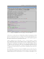
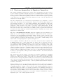
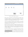
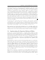
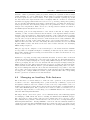
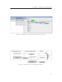
Figure 2.1 shows a screenshot of TRALE’s old source level debugger as discussed in the
previous section. In principle, the trace makes it possible to understand how the procedural
boxes are embedded into each other, and thereby the call structure. However, this information is presented in a linear fashion without any visual aid for recognizing the call hierarchy.
Unlike in a standard Prolog tracer, not even call depth information or step numbers are
provided, which makes it very hard to identify ports that belong to a common procedural
box. Without expert knowledge of TRALE’s internals, it is therefore impossible to reconstruct the call structure from the trace. A simple indentation of lines to indicate call depth
would already be an immense help, but unfeasible for highly recursive programs because of
the very limited column width of a typical console window.
While expert users can determine the call structure by careful observation of the linear trace,
the tracer does not provide sufficient information about the reasons why computations occur. Especially during backtracking, where the order in which goals are retried does not
only depend on the current call stack, but also on the alternatives that have been tried on
other paths of the search tree, it is very easy to lose track of the current state of execution.
The linear trace becomes even more confusing when cuts come into play, and the lacking
information on delayed goals makes the control flow entirely intransparent.
Another severe shortcoming of a tracer is that the tracing decisions are always made locally,
without any way to correct errors. If a user erroneously skips a step whose computation
details would have been relevant, or makes a small mistake in defining a breakpoint, there
is no way to access the missed information other than to abort and restart the tracing
process. This behavior forces the user to be very defensive, always erring on the safe side
in order to make sure that no relevant information is lost. As a result, traces tend to take
a lot longer than they would have to if context information on past steps remained accessible.
The low accessibility of non-local information during tracing is also an issue by itself. If
8
CHAPTER 2. TRALE GRAMMAR DEVELOPMENT
Figure 2.1: TRALE’s source-level debugger, embedded in XEmacs.
a user needs to look up some type constraint that is defined in the signature, the usual
predicates for feature inspection are not available during tracing. The mini-interpreter for
inspection of intermediate results is a very helpful tool, but it visually disrupts the tracing
history and requires the user to scroll back and forth a lot in order to assemble the hints on
the current execution state after spending some time in it.
Ideally, a grammar developer would want to be able to observe the influence of individual constraints during tracing. Precise information about the points in the parsing process
where constraints are applied would also make performance optimizations a lot easier. Unfortunately, the current source-level debugger does not expose this information. Instead,
the application of constraints becomes visible through its consequences, usually in the form
of a sudden traversal of a description. The source-code highlighting makes this a little less
dramatic by at least showing which rule or principle is being applied. But the reasons why
a constraint enforcement was triggered at a specific time remain hidden in the depths of the
underlying trace.
After this discussion, it should be clear that the TRALE source-level debugger has severe
shortcomings, and that any attempt to improve upon its problems holds a lot of promise for
the advancement of grammar engineering. Some fixes could more or less readily be made
within the framework of a console-based tracer, e.g. by exposing more information on con9
EXTENDING KAHINA BY A FEATURE WORKBENCH
JOHANNES DELLERT
straint enforcement through details about the underlying Prolog implementation. It would
also be possible to store some more step information and to display more information about
previous steps on demand. But for reasons that are discussed below, the decision was made
to leave XEmacs and/or the console behind in order to construct a debugging system with
a Java-based graphical user interface (GUI).
Using a graphical interface for a debugging system is perhaps not an obvious choice. Especially in the Unix community, graphical interfaces have traditionally been criticized for
forcing the user to switch between mouse and keyboard input, thereby slowing down proficient keyboard users. Graphical interfaces also tend to respond more slowly to user input,
and they invariably suffer from a trade-off of exposing as much functionality as possible
while at the same time maintaining a clear design.
These criticisms mostly apply to interfaces that merely provide buttons and menus instead
of command-line options, for no other reason than because GUIs are considered visually
attractive. In many cases, such interfaces even restrict access to the underlying system,
whose original flexibility is often important to advanced users.
In the context of interactive debugging, however, graphical interfaces have genuine advantages. The first of these advantages becomes apparent when we have a second look at the
old source-level debugger in Figure 2.1. Complex data structures such as AVMs or trees are
hard to represent linearly in a human-readable fashion. While TRALE provides pretty-print
predicates for inspecting feature structures on demand, their output is too space-consuming
to routinely be displayed as part of a trace. But the trace also gets cluttered when these
predicates are used on demand, making the control flow even less traceable. The same
problem would affect a more structured trace that provides some visual aid for determining
the call hierarchy. Mainly for this reason, SWI Prolog, the leading freely available Prolog
implementation, already includes a graphical tracer (Wielemaker, 2003).
The cure to the size problem of human-readable data structure representations is display
parallelism. Unlike command-line interfaces, GUIs can display various kinds of contextual
information at the same time, allowing data structures to be displayed in parallel for comparison, and an uncluttered trace display to be separated from a step detail window. For
these reasons, graphical front-ends for console-based debuggers are becoming increasingly
common. The DataDisplayDebugger (DDD) by the GNU Project (2011) and KDbg by Sixt
(2011) appear to be the most influential such systems in a GNU/Linux context.
For a long time, graphical tools have been used also by advanced users to receive a better
bird’s-eye overview of complex parsing processes. A case in point is Stefan Müller, the author of the most comprehensive TRALE grammar implementations (see e.g. Müller (2009)
and Müller and Ghayoomi (2010) for discussions of implemented fragments of Maltese and
Persian). Müller almost exclusively uses a custom graphical chart display for debugging
his wide-coverage grammars (personal communication), prefers to look at the source code
directly if solutions are missing, and sees little use in the old source-level debugger for his
purposes. This chart display plays the role of a visual summary of the parsing process,
making good use of shapes like curves and arrows which are difficult to render in a console,
but easy to display in a graphical environment.
Human minds tend to be lot better at understanding complex structures which are presented
as pictures than at interpreting textual formats. Therefore, graphical view components are
superior to consoles whenever non-textual information needs to be presented in a compact
and comprehensible fashion. In an area like grammar engineering, where the structures in
question quickly become very complex, not making use of this potential in the development
10
CHAPTER 2. TRALE GRAMMAR DEVELOPMENT
of advanced user-friendly tools would be a mistake.
For these reasons, all the tools for facilitating the analysis of rule interactions which are
developed in the main part of this thesis will have graphical user interfaces. To motivate
the design of these tools, the next chapter takes a look at existing graphical environments
for grammar development, and introduces the graphical debugging system which the new
tools will be built on.
11
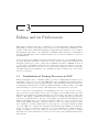
Chapter
3
Kahina and its Predecessors
This chapter investigates the use of graphical tools for understanding complex grammars
and parsing processes. In the first section, we start out by looking at the visualization components of various successful natural language parsing systems, leading us to the conclusion
that graphical approaches to the challenges of grammar engineering have been fruitful in
the past, although many of the techniques employed do not directly translate to recipes for
the TRALE case.
Section 2 introduces the Kahina debugging environment as a novel tool for visualizing parsing
processes, which also attempts to solve some of the problems of current tracer-based Prolog
debugging technology in order to make these visualizations useful for TRALE. In Section
3, some parts of the Kahina architecture are discussed in detail, preparing its role as the
implementation platform for the new tools developed in later chapters. Section 4 relates the
possibilities introduced by Kahina to the capabilities and shortcomings of the console-based
source-level debugger.
3.1
Visualization of Parsing Processes in NLP
When investigating ways to visualize parsing processes for HPSG implementations, it is
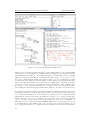
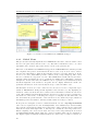
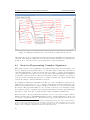
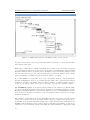
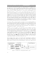
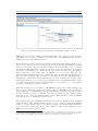
worthwhile to take a closer look at the LKB system, the only HPSG development environment which currently provides a graphical interface. The LKB system uses various windows
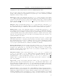
for displaying result structures as well as grammar information. The screenshot of an LKB
session in Figure 3.1 gives the reader a first impression of the system’s look and feel.
A core component of any parsing process visualization is a way to give the user access to
parse trees and/or parse charts. As we can see in Figure 3.1, the LKB features neat and
interactive representations of phrase structure trees, and a solid component for chart visualization. The display of parse trees is indispensable for quickly surveying the structures
produced for an input sentence, and due to the ubiquity of tree structures in linguistics, they
make it particularly easy to spot unexpected behavior. Therefore, even console-based tools
without any graphical interface commonly offer some way of producing pictures of parse
trees, usually by opening a small window for the purpose, or by using external programs
to produce TEX code or image files. Integrated systems such as the LKB tend to make the
nodes of a parse tree interactive, using the tree nodes as handles into partial structures.
Ideally, by clicking on a node in a parse tree, the user does not only receive more detailed
information about the substructure, but also about the parts of the grammar which licensed
that structure.
13
EXTENDING KAHINA BY A FEATURE WORKBENCH
JOHANNES DELLERT
Figure 3.1: A work session using the LKB system.
While a parse tree merely displays the result of a successful parsing process, a parse chart
contains more of the information accumulated during a parsing process. Typical chart displays summarize the parsing process by displaying all the constituents that were successfully
assigned to structures, including the constituents that later did not become part of a complete parse. Chart displays usually symbolize the spans covered by constituents as edges
over the input string. The most relevant quality of chart displays for debugging is that they
can provide valuable information about unexpected or missing parses. An unexpected parse
can often be narrowed down to an unwanted edge for a substructure, while a missing parse
is often due to some constituent that was not recognized. Both cases can quickly be identified, making the chart an extremely useful aid in looking for conceptual or notational errors.
A chart is the central data structure for almost all efficient parsing algorithms because it allows partial solutions to be reused. Exposing the chart to the user therefore already provides
a lot of essential information about the internals of a parsing process. Parsing algorithms
usually fill the chart in a way that only makes it necessary to store positive intermediate
results. However, in the case of a missing edge, a user will often be interested in finding
out not only that, but also why an expected substructure could not be established. A
chart that does not contain what I will call failed edges cannot provide interactive access
to such information. The LKB is such a case, its chart only provides information about
those computations that led to constituents being established. As a result, the information
14
CHAPTER 3. KAHINA AND ITS PREDECESSORS
about a parsing process available to the user is quite incomplete, and not only technical details are hidden. Successful and failed edges are of equal importance to a grammar developer.
To find concepts for more complete visualizations, we thus need to look beyond current
technology for HPSG implementations. In the rest of this section, we will therefore have a
look at the techniques used for visualising parsing processes in other grammar formalisms,
starting with closely related formalisms that offer comparable challenges, and then gradually
moving away to more distantly related formalisms, for which interesting tools exist.
Another constraint-based grammar formalism that has been used for implementing large
grammars is Lexical-Functional Grammar (LFG) introduced by Bresnan and Kaplan
(1982). For a comprehensive and up-to date introduction to the formalism, the reader is
referred to Bresnan (2001). The most advanced freely available system for implementing
LFGs is the Xerox LFG Grammar Writer’s Workbench documented in Kaplan and
Maxwell (1996). The system is quite similar to the LKB in both the content of windows
and their interactivity. Since syntactic analyses in LFG are separated into the two layers
of c-structure and f-structure, the LFG Workbench features separate view components for
both layers. The constituent structure is represented by a phrase structure tree, and the
functional structure by an attribute-value matrix.
An important difference to the LKB stems from the separation of the parser into a cstructure parsing component and a constraint system that subsequently enforces f-structure
constraints, which makes it easy to display legal c-structures for which no valid f-structures
could be found, providing more fine-grained feedback about the reasons for a structure to
be invalid. The LFG Workbench also provides a chart display, which contains additional
edges representing partial matches of the c-structure rules guiding the parsing process. If,
for instance, a transitive verb was recognized, but no subsequent constituent qualified as
an object, the chart receives an edge with the symbol /VP. While this comes a lot closer to
providing the desired information on failed edges, it lacks information on c-structure rules
that failed to apply because already the first constituent could not be found.
The main asset of the LFG Workbench lies in its advanced mechanisms for explaining why
failed edges could not be established, or why no valid f-structure for a given c-structure
could be found. For this purpose, all the views offer options for extending the displayed
information by invalid or incomplete structures, and selecting such a structure will highlight
the parts which were missing in a c-structure rule or which violated some f-structure constraint. While all this is extemely helpful to the grammar developer, the exact way in which
f-structure constraints are enforced still remains intransparent. This is not necessarily problematic for debugging, but it means that the LFG Workbench lacks support for grammar
optimization, because the order in which the individual constraints are enforced is neither
exposed nor manipulable.
A further interesting formalism to investigate is Weighted Constraint Dependency
Grammar (WCDG), which is unique in combining hand-crafted constraints with a preference ordering defined by manually assigned weights. Constraints with non-zero weights
are defeasible, causing grammaticality to be not any longer a binary feature, but a continuous measure. Parsing becomes a constraint optimization problem, in contrast to other
constraint-based formalisms that only require constraint solving. This leads to high computational costs, but also allows mere linguistic tendencies to be expressed, making the system
robust against extra-grammatical and even ungrammatical input. WCDG was developed by
Foth et al. (2004a) to build a large-coverage parser for German. Their grammar consists of
about 750 handwritten constraints, and was derived from about 25,000 annotated sentences.
The graphical development tools used in this effort are described in Foth et al. (2004b).
15
EXTENDING KAHINA BY A FEATURE WORKBENCH
JOHANNES DELLERT
The tools of the WCDG system are important in our context because they possess some
unique features that make the grammar engineering process very different from other systems. A central dependency tree visualization component works both as a display module
for intermediate structures and as an editor that allows to modify parsing results for subsequent hypothetical evaluation. In this mode, the parser explains which constraints and
which weights prevented it from preferring the user-defined structure, giving the grammar
engineer precise information about the rules which would have to be assigned higher or lower
weights to achieve the desired behavior.
This is possible because every configuration of dependency arcs and nodes is admissible
by default, and the parser uses the constraints only to discard parses under an exclusion
paradigm. While in theory, this is also the case for the HPSG formalism, the parsers of
both TRALE and the LKB are built around a context-free backbone, and thereby at least
partially operate under a licensing paradigm. The resulting difference in efficiency shows in
the sluggish performance of the WCDG parser in comparison to these systems. However,
for debugging purposes, having a parser that solely operates under the exclusion paradigm
turns out to be preferable, since this allows to find out which constraints are violated in an
arbitrary structure. Since no other state-of-the-art parser works in this way, the WCDG
tools’ special features are difficult to emulate in the context of other parsing environments,
but they can still serve as an inspiration for future grammar engineering systems.
Going beyond constraint-based approaches, we will next look at visualization tools for Tree
Adjoining Grammar (TAG), a mildly context-sensitive grammar formalism that is built
on combining trees instead of strings. During structure derivation, tree fragments from a
grammar are combined using adjunction (insertion) and substitution operations. Joshi and
Schabes (1997) give a comprehensive formal introduction to TAGs and their properties.
The most popular development environment for TAG grammars is formed by the XTAG
tools, which were created as part of the XTAG project (Doran et al., 1994), a long-term
effort to develop a TAG-based wide-coverage grammar for English. Paroubek et al. (1992)
give a concise, though somewhat outdated, description of the XTAG graphical development
environment. More recent information is available through the XTAG project’s website (see
University of Pennsylvania, 2011).
The XTAG graphical interface is centered around the manipulation of trees as elementary
objects. It includes a graphical tree editor, facilities for exploring both derivation trees and
derived trees, and also some support for manipulating simple feature structures (which can
be used to enrich nodes in the XTAG formalism). All of these components are used to define
grammars in the XTAG system. Unlike in many other systems, grammars are not specified
via a text format, but directly in terms of graphical tree structures.
For the visualization of parsing processes, XTAG mainly provides a display of derivation
trees, which contain all the essential information about how a tree was derived, and whose
nodes are linked to displays of the corresponding elementary trees. This makes the derivation
tree display analogous to the source code display for chart edges in TRALE. However, such
a display does not expose as much detail about the internal computations, as it causes chart
states and especially failed attempts to combine elementary trees to be hidden from the user.
A very interesting property of XTAG, which inspired the development of the feature workbench in Chapter 6, is that it allows to interactively execute tree operations such as adjunction and substitution for manual testing. This mechanism, together with the design as a
central buffer of tree structures to which operations can be applied, with the results ending
up again in the buffer, makes it possible to emulate entire parsing processes.
16
CHAPTER 3. KAHINA AND ITS PREDECESSORS
A more modern, though less mature, development environment for TAGs is the Tübingen Linguistic Parsing Architecture (TuLiPA) presented by Kallmeyer et al. (2008).
Unlike the XTAG tools, TuLiPA does not contain tools for graphical editing of TAG grammars. Instead, it relies on the XMG (eXtensible MetaGrammar) approach described
by Crabbé (2005) for this purpose. However, in comparison to XTAG, TuLiPA’s visualization components are more focused on making complete parsing processes transparent, and
are much less tuned towards interactive grammar exploration.
As in XTAG, both derivation trees and derived trees are interactively visualized. The
elementary trees contributing to a derivation are made accessible as well. The heavily lexicalized nature of typical TuLiPA grammars makes it feasible to also display the structures
where some feature clash occurred, highlighting the problematic parts in partially derived
structures. The intermediate results after each adjunction or substitution step can optionally be displayed, which makes the parsing processes more transparent than in XTAG, even
though TuLiPA lacks facilities for manually executing adjunctions and substitutions.
For even more distant grammar formalisms such as Combinatory Categorical Grammar
(CCG) or even plain CFG, a parse chart is usually sufficient because the rules for filling the
chart are very local and easy to track. In general, the less complex the categories that need
to be grouped into constituents become, and the more dominant simple phrase structure
rules become for parsing, the less the user will gain by receiving extensive information about
the parser’s internal workings.
As statistical approaches to NLP also tend to only rely on local contexts and shun complex
interactions for easier model learnability, the few visualization tools are normally just used
to quickly survey the consequences that changes in learning parameters have on system
behavior. This makes graphical representations for statistical parsing an area unlikely to be
of much help for our purposes.
3.2
Introducing the Kahina Architecture
We now turn our attention to Kahina (Dellert et al., 2010), a novel debugging framework
which developed out of a graphical frontend for TRALE’s source-level debugger. The more
recent versions of Kahina provide advanced general debugging facilities for logic and constraint programming. The system expands on earlier ideas for graphical Prolog debugging
presented by e.g. Dewar and Cleary (1986) and Eisenstadt et al. (1991), and is heavily
inspired by SWI-Prolog’s GUI tracer (Wielemaker, 2003), which is the most mature visualization tool for Prolog processes currently available.
The Kahina system is built around the concept of the computation step. Representations of
such steps can be arranged in global data structures such as control flow graphs, and data
of arbitrary type can be assigned to the individual steps. In the case of TRALE, a step is
associated with information on the respective operation (e.g. unification, mgs computation,
or goal execution), a source code line, and a snapshot of relevant data at that step (e.g.
feature structures and variable bindings).
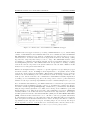
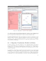
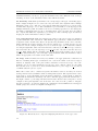
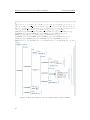
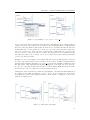
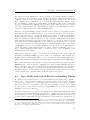
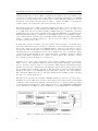
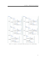
The architecture of the Kahina-based TRALE debugger is sketched in Figure 3.2, as an aid
for understanding the somewhat complex relations between the various system components.
Kahina as a framework is implemented entirely in Java, and currently consists of about
38.000 lines of code. The Java Swing library is used for the graphical interface code. The
entire source code of Kahina and all the components developed in this thesis is distributed
under a GPL license via the system’s webpage (see Evang and Dellert, 2011).
17
EXTENDING KAHINA BY A FEATURE WORKBENCH
JOHANNES DELLERT
Figure 3.2: Architecture of the Kahina-based TRALE debugger.
A Kahina-based debugger is started by creating a KahinaInstance object, which mainly
consists of a KahinaState and a KahinaController, and communicates with a KahinaGUI.
The KahinaState manages a step database containing the step data as well as one or more
data structures to model the relations between steps (such as call trees and charts), caching
step data into temporary files if they become too large. The KahinaGUI includes a window manager coordinating various GUI elements, and it provides functionality for creating
and manipulating windows. The KahinaController is responsible for message exchange
between the various components of the system. Whenever I use the name “Kahina” in this
thesis, I refer to this general Java framework.
Kahina can straightforwardly be adapted to a specific application by specifying step types
and their relevant content. A bridge is then implemented to encapsulate all the traffic
between the client application and Kahina. This includes transmitting the step detail information as well as handing back control instructions, such as tracing commands, to the
client process. On the client side, the communication with Kahina is usually implemented
by adding code for transmitting step data to the bridge, and a control loop that interleaves
with the execution process and prompts Kahina for a user command telling it how to proceed.
For both SICStus and SWI-Prolog, the Kahina distribution comes with Prolog libraries that
implement both the transmission and the control loop, and which are configured for interaction with a default LogicProgrammingBridge. SICStus Prolog communicates with Kahina
using the Jasper library (Carlsson et al., 2009, Section 10.43), and for SWI-Prolog, the JPL
library (Singleton et al., 2011) is used. Because only a SICStus Prolog version of TRALE is
currently available1 , the architecture sketch only mentions the Jasper interface. Both Jasper
and JPL spawn and address a Java Virtual Machine (JVM) via the Java Native Interface
(JNI), a framework that enables Java code to call and be called by programs and libraries
in other languages as native processes that run outside the JVM. The JNI is a lot less stable
than other parts of standard Java distributions, so that both Jasper and JPL are considered
experimental by the respective developers, and using Jasper is even actively discouraged.
In our experience, however, both interfaces are reasonably stable, and they allowed us to
1 Other
18
versions (e.g. for SWI Prolog) exist, but have not yet been made publicly available.
CHAPTER 3. KAHINA AND ITS PREDECESSORS
avoid dealing with separate processes and sockets for inter-process communication. When
creating debuggers for systems implemented in Prolog, Kahina’s libraries are often sufficient
to make client-side adaptations unnecessary, shifting the main focus in creating an advanced
debugger to specializing the LogicProgrammingBridge for the respective client program.
As the second step in creating a customized debugger, custom data types and specialized
views can be added to Kahina’s modular data and view models. In the case of TRALE,
for instance, we implemented a specialized view component for the chart, and integrated
an existing view component for typed feature structures as AVM (Attribute-Value Matrix)
representations. We will have a look at the chart display in the next section. The feature
structure visualization will be discussed extensively in Chapter 5, since it provides the basis
for the feature structure editor.
Kahina-based debuggers for several logic programming systems are available through the
system’s website. The versions for SWI-Prolog and SICStus Prolog are not yet as fully
developed as the new TRALE debugger, but they provide an excellent basis for creating
Kahina debuggers for other Prolog programs. Because all the functionality specific to logic
programming is contained in a separate package (org.kahina.lp), the very general core
system in org.kahina.core can also be used for creating debuggers outside of the logic
programming paradigm.
3.3
Visualization and Control Mechanisms in Kahina
When a logic programming system loads its Kahina debugger, it hands over control to the
respective bridge, periodically prompting it for tracing instructions. The tracer interface
is exposed by a control panel in Kahina’s main window, which provides the basic tracing
commands of the old source-level debugger as mnemonic buttons that can still be operated
by using the old single-key instructions. In reflection of the new possibilities for step data
storage, a distinction is made between the operations of skipping and auto-completion. Skipping is directly translated into a skip command for the tracer, discarding the details of the
skipped steps, whereas auto-completion executes the same skip using a sequence of creep
commands, collecting and storing the step information for all intermediate steps. Given the
amount of data that needs to be transferred to Kahina in the auto-completion case, it is not
surprising that auto-completion is a lot slower than skipping.
A Kahina-based debugger comes with a range of predefined view components, which are
either local views intended to visualize the data associated with the currently selected step,
or global views that expose some aspect of the overall structure of parsing processes. Kahina
allows the user to freely arrange these views into windows, although some useful view and
window configurations (called perspectives) are distributed with the respective debugger.
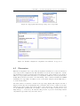
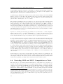
In the case of TRALE, Kahina currently provides three global and four local views, which I
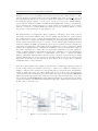
extend by two more global view components in this thesis. Figure 3.3 contains a screenshot
of the new TRALE debugger, showing many of the view components that we will talk about
in this section.
The views are free to interact via the controller, which allows listeners to register themselves
for different message types, and later distributes messages on user interactions or data model
changes to all components currently interested in the respective message type. For instance,
this makes it possible to dynamically change the step details displayed in the local views
when a step is selected in one of the global views.
19
EXTENDING KAHINA BY A FEATURE WORKBENCH
JOHANNES DELLERT
Figure 3.3: A session of the Kahina-based TRALE debugger.
3.3.1
Global Views
The global views currently implemented for TRALE allow the user to interact with a control
flow tree, the parse chart, and the source code. We will not discuss the source code editor
any further, since it has no importance in the context of the present work.
The heart of the Kahina-based TRALE debugger is the control flow tree, which represents
the computation steps as nodes and allows the user to select every node in order to retrieve
the associated information, which is then displayed in the local views. Each node in the
tree is color-coded to mark which port last occurred on the corresponding step. The control
flow tree combines two aspects in one view. The search tree is symbolized by the macro
structure which determines the tree’s overall layout, making the backtracking completely
transparent. At the same time, the call tree can be represented by indentation levels in
the linear fragments of the search tree. Together, the two display dimensions contain comprehensive information on the reasons why the steps occurred in which order.
An alternative view mode for the control flow tree is based on a more compact list representation. This list tree view puts less emphasis on the search tree by only displaying one
branch at a time, but allows the user to switch between alternative branches at each choice
point. The resulting less hierarchical structure uses up a lot less screen space, leaving more
real estate for other views, or allowing more steps to be displayed at the same time. On
the other hand, the global structure of the search tree is not visible any longer, which is a
disadvantage if the user wants to find the branches where most steps occurred.
To keep the tree navigable even if it contains thousands of nodes, a layering mechanism
can be used to separate the tree into meaningful units. User-definable layer deciders classify
the nodes into layers that are numbered by importance, where each layer is more important
than all the layers with higher IDs, so that layer 0 contains the most important nodes.
When computing a tree view at some layer, the nodes of more important layers are treated
as corner-stone nodes, which define the context boundaries where the tree fragment of
the display is pruned. Displays at different layers are connected by a common context node.
20
CHAPTER 3. KAHINA AND ITS PREDECESSORS
Navigation in the tree works by selection, which redefines the context node and causes the
displays at all layers to adapt. The effect of the layers can be compared to zoom levels, where
the layer decider determines how much detail is visible at each level, and the corner-stone
nodes define the boundary of the zoom window.
The chart display lists the edges as blocks arranged over the input string. The TRALE
parser proceeds by trying to establish edges according to phrase-structure rules in a right-toleft bottom-up fashion, which makes the chart a very helpful component for understanding
which structure the parser is currently working on. Chart edges are tightly coupled with
the corresponding parsing steps, allowing the user to jump to the relevant position in the
control flow tree by selecting a chart edge. This coupling of steps and the chart also works
the other way around: whenever the user selects a step in the control flow tree or in the
trace-like message console, the chart display highlights the edge that this step contributed
to. The highlighting can be configured to also include the descendants and/or the ancestors
of the selected edge, providing an intuitive visualization of the edges that contributed to the
current edge, or the uses of the current edge in establishing larger constituents.
In addition to the display of all edges that could be established (in green), the chart display
allows the user to selectively display all the failed edges (in red) for some phrase-structure
rule. The step IDs associated with the failed edges will carry a user directly to a step where
the corresponding rule failed, providing direct and detailed access to the reasons why some
edge could not be established. However, backtracking often makes it impossible to identify
a single step whose failure is responsible for the failure of a superordinate goal. Therefore,
while trying to construct an edge, we usually encounter many substeps which fail, but do
not prevent the edge from being established. Conversely, if a predicate fails, it usually fails
multiple times (once in every branch of the search tree), leading to a confusing proliferation
of failed edges on the chart. A few simple heuristics for distinguishing relevant and spurious
failures somewhat alleviate this problem, but the conceptual difficulty remains.
3.3.2
Local Views
The local views for TRALE currently display feature structures and variable bindings at
the respective ports of the current step. Virtually all the step types that occur during a
parsing process amount to a manipulation of feature structures, and can therefore most
informatively be visualized by an AVM representation of the structures involved. Kahina’s
approach to feature structure visualization is discussed extensively in Chapter 5. Experience has shown that in comparison to only displaying the substructure that is modified by
a step, highlighting it in a larger context structure makes it easier to understand how the
different steps contribute to structure manipulation. For instance, when creeping through
the complex process of matching a feature structure against a description, this is graphically
depicted by parallel highlights closing in on substructures and marking the places were local
modifications occur.
In addition to the context structure, the bindings for all the variables used in the definition
of the respective predicate are accessible via another view. As variables are bound to feature
structures, a variable bindings display consists of a list of context variables and a small
instance of the feature structure display to present the selected variable’s current value in a
human-readable fashion.
Both the feature structure and the variable binding views are separated into two windows
representing the state before and after the computation step. Because the feature structure
display highlights the parts of the context structure that have changed between ports, it
implicitly provides a diff functionality, which makes it easy to determine the data structure
manipulations occurring at every step in the control flow tree.
21
EXTENDING KAHINA BY A FEATURE WORKBENCH
3.3.3
JOHANNES DELLERT
Breakpoint System
Just like in the old SLD, rapid navigation of a parsing process towards a point of interest
requires some functionality beyond the basic tracing commands. For this purpose, Kahina
features a powerful breakpoint system which, in addition to its obvious use in defining
breakpoints, is also used for both pattern search and workflow automation. In addition to
putting breakpoints on source code lines as in the old SLD, breakpoints can be defined by
pattern matches using regular expressions over step descriptions, or regular tree patterns
ranging over substructures of the control flow tree. Such patterns allow to define breakpoints in a very fine-grained manner. For instance, its is possible to single out only those
unification steps which involve synsem:category values and occur while trying to apply
the Head Feature Principle.
All these patterns can be freely combined using boolean expressions, and they can be extended by counters, which in turn can be furnished with numerical constraints. For instance,
this makes it possible to define a breakpoint which only fires at every tenth match of some
tree pattern. Collections of breakpoints can be administered and edited using a graphical
breakpoint editor, which includes a tree editor as an intuitive method for defining tree
patterns.
The breakpoint system can also be used for searching through the step database, by temporarily defining a breakpoint and running it over the existing control flow tree. The message
console will then show all the matches, each line acting as a link for selecting and scrolling
to the matching node. All of the patterns that can be used in breakpoint definitions can
serve as search patterns in this way.
The standard behavior of a breakpoint is to interrupt leap operations when a situation
matching its pattern is encountered. Kahina offers a range of non-standard breakpoint
types for process automation. For each of the basic tracing commands, a corresponding
breakpoint type exists. In analogy to the term breakpoint, these are called skip points, creep
points, and fail points, and trigger the respective tracing command when their patterns are
matched. This automation mechanism can greatly increase the efficiency of debugging, e.g.
by telling the tracer to automatically skip over all applications of a phrase structure rule
that can safely be assumed to contain no bugs. A warn point is a breakpoint with an
associated message that is displayed in a pop-up window when the pattern matches. Warn
points can e.g. be used to catch infinite recursion when debugging a non-terminating parse,
or to provide warnings when a part of the implementation seems particulary inefficient.
This powerful breakpoint system can also be used to emulate the control strategies of the
old source-level debugger. Putting a leash on a step type can be emulated by defining a
breakpoint with a pattern matching that step type. Of course, the more powerful patterns
make the possibilities for leashing a lot more fine-grained than in the old SLD. The same
holds for auto-skipping, which corresponds exactly to defining skip points whose patterns
match the step types. Finally, the breakpoint mechanism of the old SLD is subsumed by the
Kahina breakpoint system because source code line numbers are supported as elementary
patterns.
3.4
Discussion
After this quick tour of the Kahina system, we will now see which problems of the old
source-level debugger are solved by Kahina, which problems remain unresolved, and also
the weaknesses the system currently still has.
22
CHAPTER 3. KAHINA AND ITS PREDECESSORS
One of the most pressing problems of the old SLD, that of determining the current state
of execution, can be considered resolved. By the combination of a chart and a control flow
graph, the position of each step in the process is in principle completely transparent. The
secondary tree dimension based on indentations also allows grasping the call structure much
more quickly than before. Although neatly splitting up control flow information into the
respective layers without losing too much of the gained transparency turned out to be quite
a challenge, already the current approximate solution has proven to be highly useful even
for inexperienced grammar implementers.
The fact that all the data associated with the traced steps is stored for later retrieval offers the user the novel option of post-mortem analysis, i.e. inspection of computation
steps even after they were processed. This means that the user is no longer forced to decide beforehand whether a step can be skipped, and retrace the entire process in case of
unexpected behavior. Instead, it is now possible to auto-complete a step, but still inspect
the computations involved if the skipping decision was erroneous or too optimistic. Tracing
decisions are thus still local, but can to some extent be revised, allowing the user to behave
less defensively during debugging.
Interactivity with many windows open at the same time allows the user to configure views
according to her information needs. While inspecting a computation step, the control flow
diagram, the soure code location, variable bindings as well as input and output feature structures can all be visualized in parallel. This display parallelism has increased the accessibility
of non-local information enormously.
Turning to the weaknesses of the Kahina architecture, it comes as no surprise that an interface with this many different views chronically suffers from shortage of screen space.
Combining all these views in just one screen leads to a very crowded interface, forcing the
user to scroll views and to manipulate window sizes and positions quite frequently. Ideally,
a grammar implementer will therefore want to use at least two high-resolution displays. In
order to avoid any compromise in the amount of information that can be displayed in parallel, the Kahina window manager provides comprehensive support for distributing windows
over several screens, turning this issue more into one of hardware than of design.
A more severe disadvantage is the speed of step data collection, which is partially caused
by the need to assemble the feature structures on the Prolog side, but mostly by the delay
in every foreign method call via the Jasper interface. As a result, in auto-complete and
leap mode (which have evolved to be very popular with users), on a typical machine of
this day only the details for about 30 steps per second are transmitted. This low speed is
especially disturbing if Kahina is configured to retrieve all the step information even for the
tiniest step, not making use of skip points to limit the expensive step detail transmission on
points of interest. This makes skip points a core mechanism for an efficient workflow, but
they are unfortunately often overlooked by users because their administration is hidden in
a submenu. Therefore, it is planned to integrate them more prominently in the user interface.
A further weakness of the current architecture is that it only provides rudimentary support
for error handling. If run-time errors happen on the Prolog side (e.g. because of erroneous
inputs), the error messages are not yet displayed inside of Kahina, forcing the user to
check the console from which TRALE was started. Moreover, Prolog errors often cause
the underlying trace in the old SLD to abort, causing Kahina to be disconnected from
the underlying tracer, making it unresponsive and forcing the user to restart the process.
We plan to fix these problems in the future by extending the bridge interface by another
communication channel.
23
EXTENDING KAHINA BY A FEATURE WORKBENCH
JOHANNES DELLERT
Coming to more TRALE-specific weaknesses, one problem is that delayed goals are still not
visualized in a satisfying way. The current version of the Kahina-based debugger uses special
nodes in the control flow tree to mark the points where goals are delayed, and the steps that
result from the resumption of such a goal are connected to the delay point by a link that can
be followed. As a result, the execution of a delayed goal does not any longer cause the user
to lose track of the execution state, but it can still be a rather surprising event. This could
be improved by displaying the suspended goals in an additional view component, visualizing
the conditions for resumption in a transparent way. Attempts will be made to develop such
a view component for future versions of Kahina.
Finally, grammar compilation and parsing processes can be started using the debugger’s
Parse menu, but due to its origin as a mere graphical frontend, Kahina does not yet include
any facilities for defining test suites. An option to define projects consisting of grammar files
and test parses has a high priority for inclusion in future versions of Kahina. In connection
with the introduction of test suites, Kahina’s rudimentary profiling facilities will also have
to be extended.
Despite the current shortcomings, and even though the Kahina architecture is far from mature, the Kahina-based debugger is stable enough to have replaced the old SLD as the default
debugger in recent versions of TRALE. Despite its current lack of documentation, various
students (e.g. Nomi Meixner and Anne Brock, personal communication) who implemented
or extended grammars for seminar papers at the University of Tübingen, have confirmed it
to be very useful in comparison to its console-based predecessor.
24
Chapter
4
Signature Inspection and Visualization
A core element of a constraint-based grammar is the specification of the structural domain
that the constraints apply to. In a typed feature logic system, this is commonly achieved by
a signature which considerably restricts the space of allowed feature structures before more
complex constraints are enforced.
When getting an overview of a grammar implementation, analyzing the signature is the first
step to understanding which linguistic phenomena are covered, and how they are modeled
in the grammar. The signature also contains much information on how structures can be
manipulated during a parsing or generation process. Unfortunately, signatures are in essence
graph structures extended by a rather involved inheritance schema, which makes them hard
to grasp especially for the novice user.
This chapter deals with the design of tools for user-friendly signature inspection, where a
natural focus lies on useful visualization strategies for the information encoded in a TRALE
signature. Section 1 introduces the necessary formal notions as well as a running example.
In Section 2, existing approaches to signature visualization are described, leading to a more
general discussion of the representation issues in Section 3. Section 4 presents a novel
signature visualization approach, which is inspired by Javadoc and implemented as a Kahina
view module. The chapter concludes with a discussion of the advantages and problems of
the new view module in Section 5.
4.1
TRALE Signatures and the Type System
We begin by formally introducing the type system as implemented in TRALE. The terminology as well as the notation is slightly adapted from Carpenter (1992), whereas information
about the variant implemented in TRALE was derived from the ALE User’s Guide by Penn
et al. (2003).
Definition 4.1.1. Let Ty be a finite set of symbols called types, and let v be an ordering
relation on Ty. For σ, τ ∈ T y, we say that σ subsumes τ or σ is more general than τ
iff σ v τ . In that case, we also say that σ is a supertype of τ or that τ is a subtype of σ.
In applications, the subsumption ordering can often intuitively be understood as expressing
degrees of informativity. The more general a type is, the less information it contains. For
instance, if we know of a linguistic object that it is a fricative, we also know that it is a
consonant, but we have the additional information that it is not a plosive. This could be
modeled by a type consonant subsuming, among others, the subtypes plosive, nasal, and
fricative.
25
EXTENDING KAHINA BY A FEATURE WORKBENCH
JOHANNES DELLERT
Definition 4.1.2. A set Ty of types is said to be consistent if they share a common subtype
or upper bound σ such that τ v σ for every τ ∈ Ty.
Definition 4.1.3. A type σ is the least upper bound (or join) of a subset S ⊆ Ty iff
∀τ ∈ S τ v σ, and σ v υ for every other υ ∈ Ty where ∀τ ∈ S τ v υ.
Definition 4.1.4. A partial order is called bounded complete iff for every set of elements
with an upper bound there is a least upper bound.
Definition 4.1.5. An inheritance hierarchy is a finite and bounded complete partial
order hTy, vi, i.e. a finite set of types where every consistent subset of types has a most
general subtype.
TRALE’s type hierarchies are thus in essence acyclic inheritance graphs. An inheritance
hierarchy can be defined using a set of elementary is-a pairs, defining a relation C that
needs to be antisymmetric, but not necessarily reflexive or transitive. The complete subsumption relation v is then defined as the reflexive transitive closure of C. As we shall see,
elementary is-a pairs are the entities employed by the user for signature definitions.
Because the tools we develop are designed to present information and options in a format
as close as possible to the user’s definitions, many of the later formal definitions will rely on
the graph structure defined by C instead of its reflexive transitive closure v.
Definition 4.1.6. An appropriateness specification over an inheritance hierarchy
hTy, vi and a finite set of features Fe is a partial function A : Fe × Ty → Ty which meets
the following conditions:
(1) (feature introduction): for every f ∈ Fe there is a most general type
Intro(f ) ∈ Ty such that A(f, Intro(f )) is defined.
(2) (upward closure): if for f ∈ Fe, σ, τ ∈ Ty and σ v τ , A(f, σ) is defined,
then so is A(f, τ ), and A(f, σ) v A(f, τ ) holds.
Intuitively, an appropriateness specification encodes information we have (or postulate)
about an object and its relations to other objects if we know about its type. In our phonology
example, we could introduce the places of articulation under a type place in another part
of the type hierarchy and state that that each consonant introduces a feature place whose
value is of type place by defining A(place, consonant) := place. Upward closure would
then ensure that a place value of type place is also defined for the subtypes of consonant.
Definition 4.1.7. A signature is a quadruple hTy, v, Fe, Ai composed of an inheritance
hierarchy hTy, vi, a finite set of features Fe, and an appropriateness specification A : Fe ×
Ty → Ty.
Throughout this thesis, we will make use of a simple toy grammar to provide us with examples for the theory and implementation of the new tools. The demo grammar is the last
introductory example (Grammar 4, Version 3) in Richter (2005). Appendix A contains the
signature file for this grammar in TRALE format.
We will not discuss the specifics of this format here, but the reader should notice that it can
be conceptualized as pairs defining the C relation, expressing differences that get lost during
the closure operation leading to v. The signature defines bot C cont and cont C arg, but
also bot C arg, although this last pair would be unnecessary in the definition of a v relation.
As an example of the formalization just introduced, Figure 4.1 contains the complete formal
definition of the same signature. Figure 4.2 enhances this by an intuitive visualization
which expresses the type hierarchy as well as the appropriateness conditions in a graph.
This representation is not entirely intuitive in displaying the bot (“bottom”) type at the
top, but it adheres to the equally justified convention that supertypes are positioned higher
than their subtypes. Using these three representations, the reader will have no difficulty in
understanding the signature that will serve as our running example.
26
CHAPTER 4. SIGNATURE INSPECTION AND VISUALIZATION
h{acc, arg, bin rel, bse, bot, case, cat, cont, conx, dat, e list, f em, f emale rel, f in,
f irst, gender, give rel, head, index, list, love rel, masc, more arg rel, ne list,
nom, nom obj, noun, number, person, phrase, plur, relations, sign, sing,
speaker rel, synsem, think rel, third, un rel, verb, vf orm, walk rel, word},
{(acc, acc), (arg, arg), (arg, bin rel), (arg, f emale rel), (arg, give rel), (arg, index),
(arg, love rel), (arg, more arg rel), (arg, relations), (arg, speaker rel),
(arg, think rel), (arg, un rel), (arg, walk rel), (bin rel, bin rel), (bin rel, love rel),
(bin rel, think rel), (bot, acc), (bot, arg), (bot, bin rel), (bot, bot), (bot, bse), (bot, case),
(bot, cat), (bot, cont), (bot, conx), (bot, dat), (bot, e list), (bot, f em), (bot, f emale rel),
(bot, f in), (bot, f irst), (bot, gender), (bot, give rel), (bot, head), (bot, index), (bot, list),
(bot, love rel), (bot, masc), (bot, more arg rel), (bot, ne list), (bot, nom), (bot, nom obj),
(bot, noun), (bot, number), (bot, person), (bot, phrase), (bot, plur), (bot, relations),
(bot, sign), (bot, sing), (bot, speaker rel), (bot, synsem), (bot, think rel), (bot, third),
(bot, un rel), (bot, verb), (bot, vf orm), (bot, walk rel), (bot, word), (bse, bse), (case, acc),
(case, case), (case, dat), (case, nom), (cat, cat), (cont, arg), (cont, bin rel), (cont, cont),
(cont, f emale rel), (cont, give rel), (cont, index), (cont, love rel), (cont, more arg rel),
(cont, nom obj), (cont, relations), (cont, speaker rel), (cont, think rel), (cont, un rel),
(cont, walk rel), (conx, conx), (dat, dat), (e list, e list), (f em, f em),
(f emale rel, f emale rel), (f in, f in), (f irst, f irst), (gender, f em), (gender, gender),
(gender, masc), (give rel, give rel), (head, head), (head, noun), (head, verb),
(index, index), (list, e list), (list, list), (list, ne list), (love rel, love rel), (masc, masc),
(more arg rel, bin rel), (more arg rel, give rel), (more arg rel, love rel),
(more arg rel, more arg rel), (more arg rel, think rel), (ne list, ne list),
(nom, nom), (nom obj, nom obj), (noun, noun), (number, number), (number, plur),
(number, sing), (person, f irst), (person, person), (person, third), (phrase, phrase),
(plur, plur), (relations, bin rel), (relations, f emale rel), (relations, give rel),
(relations, love rel), (relations, more arg rel), (relations, relations),
(relations, speaker rel), (relations, think rel), (relations, un rel), (relations, walk rel),
(sign, phrase), (sign, sign), (sign, word), (sing, sing), (speaker rel, speaker rel),
(synsem, synsem), (think rel, think rel), (third, third), (un rel, f emale rel),
(un rel, speaker rel), (un rel, un rel), (un rel, walk rel), (verb, verb),
(vf orm, bse), (vf orm, f in), (vf orm, vf orm), (walk rel, walk rel), (word, word)},
{arg1,arg2,arg3,backgr,case,category,content,context,dtr1,dtr2,
gender,hd,head,index,number,person,phon,subcat,synsem,tl,vform},
{(arg1, bin rel) 7→ arg, (arg1, f emale rel) 7→ arg, (arg1, give rel) 7→ arg,
(arg1, love rel) 7→ arg, (arg1, more arg rel) 7→ arg,
(arg1, relations) 7→ arg, (arg1, speaker rel) 7→ arg,
(arg1, think rel) 7→ arg, (arg1, un rel) 7→ arg, (arg1, walk rel) 7→ arg,
(arg2, bin rel) 7→ arg, (arg2, give rel) 7→ arg, (arg2, love rel) 7→ arg,
(arg2, more arg rel) 7→ arg, (arg2, think rel) 7→ arg,
(arg3, give rel) 7→ arg, (backgr, conx) 7→ list, (case, noun) 7→ case,
(category, synsem) 7→ cat, (content, synsem) 7→ cont,
(context, synsem) 7→ conx, (dtr1, phrase) 7→ sign, (dtr2, phrase) 7→ sign,
(gender, index) 7→ gender, (hd, ne list) 7→ bot, (head, cat) 7→ head,
(index, nom obj) 7→ index, (number, index) 7→ number,
(person, index) 7→ person, (phon, phrase) 7→ ne list,
(phon, sign) 7→ ne list, (phon, word) 7→ ne list, (subcat, cat) 7→ list,
(synsem, phrase) 7→ synsem, (synsem, sign) 7→ synsem,
(synsem, word) 7→ synsem, (tl, ne list) 7→ list, (vform, verb) 7→ vf orm, }i
Figure 4.1: Demo signature from Appendix A, in formal notation.
27
EXTENDING KAHINA BY A FEATURE WORKBENCH
JOHANNES DELLERT
Figure 4.2: Demo signature from Appendix A, visualized as a graph.
28
CHAPTER 4. SIGNATURE INSPECTION AND VISUALIZATION
4.2
Previous Approaches to Signature Inspection
The example visualization in Figure 4.2 looks nice and comprehensible, but only because it
does not show the problems we run into when we try to visualize signatures that go beyond
small toy examples. Already an HPSG grammar for a small fragment of English, like that
in the appendix of Pollard and Sag (1994), contains more than a hundred types. Depending
on the approach to modeling phonetics and semantics, the size of the type hierarchy can
easily reach a four-digit number.
An early computational tool for interactively representing the type hierarchy of a typed
feature logic was included in the LKB system. Figure 4.3 shows the LKB’s display of a
type hierarchy belonging to one of its example grammars. Type subsumption relations are
indicated with lines in a very compact and rather schematic graph layout. To make such
graphs more easily explorable, it is possible to selectively collapse subhierarchies. Specific
information about the types’ properties is not displayed as part of the graph structure, but
instead it is accessible via a context menu option which opens up a separate feature structure
view where the entire LKB type definition (which includes constraints, see Section 2.1) is
displayed in a textual format.
The Java tool MorphMoulder (MoMo), which was originally presented by Richter et al.
(2002) as a tool for teaching the formal foundations of HPSG, and was later extended to
description logics in Ovchinnikova and Richter (2007), can also be used as an aid for interactively exploring TRALE signatures. MoMo focuses on visualizing logical relationships
between signatures, descriptions and interpretations. A screenshot of MoMo during a work
session with our example signature is provided in Figure 4.4.
For the signature information, MoMo uses a text editor window in which a signature file
in TRALE syntax can be edited. This format is compact, but not interactive, and does
not explicitly represent multiple inheritance or the consequences of upward closure on the
appropriateness conditions. MoMo is relevant for the tools we are developing because of the
high interactivity of its other components, which allows students to extensively experiment
with the formalism. Being able to manually build interpretations and check them for appropriateness against a signature constitutes a valuable aid in thoroughly understanding the
formal foundations of HPSG. The facilities can be used to understand which structures are
licensed by a given signature, which provides an intuitive handle to the abstract structural
constraints it encodes.
The educational focus has negative consequences for MoMo’s usefulness as a grammar
writer’s tool. Structures over a signature are depicted by very colorful and space-consuming
graph models, which is important to weaken the erroneous intuition that AVMs were the
interpretations of descriptions (while in reality, they are merely a representation format that
can be used for descriptions and structures alike), but makes the displays of interpretations
corresponding to feature structures as they occur in a grammar implementation really large
and hard to understand.
Further pursuing the idea of representing the entire information contained in a signature
explicitly in a single view, Ralf Kibiger (2009) implemented a dynamic graph visualization
for TRALE signatures. Relying on the open-source Java Graph Visualization Library by
JGraph Ltd (2011), the result is conceptually very similar to the visualization in Figure 4.2,
but it adds some interactivity. Nodes representing types can be freely rearranged, collapsed
and expanded, and the HTML content of the nodes was made editable to allow for annotations and reformatting. In Figure 4.5, a screenshot of Kibiger’s visualization component
displaying a part of our example signature is shown.
29
EXTENDING KAHINA BY A FEATURE WORKBENCH
JOHANNES DELLERT
Figure 4.3: LKB type hierarchy view, context menu providing various options.
Unfortunately, the use of a rather heavy-weight explicit graph visualization means that only
a fraction of the signature display fits on the screen at a time, and that a lot of display space
is wasted due to the rather wide topological structure of typical signatures.1
4.3
Issues in Representing Complex Signatures
Historically, research on the visualization of graph structures has focused very much on efficiency. Graph layout algorithms tend to become NP-complete rather fast, and with the
computing infrastructure of earlier decades it was not possible to compute an appealing layout for a graph with more than a few nodes in real time. The LKB signature visualization
recognizably comes from that age. The layout algorithm consists of a simple topological sort
of the type lattice, printing each layer into a column of strings, and crudely drawing lines
between the strings to indicate inheritance relations.
As exemplified in Kibiger’s visualization module, for today’s visualization technology, the
main issue is not any longer one of too complex computations. On modern machines, computing a near-optimal layout for a graph consisting of thousands of nodes is perfectly feasible
in real time. The problem has shifted to the other side of the keyboard. Nowadays, it is the
user’s limited capacity of grasping and extracting information from large graph structures
that puts a bound on the size of graph structures where visualization makes sense.
Even if the size of the type inheritance structure does not exceed the bounds of what a
human can make sense of (and TRALE signatures tend to remain within these bounds, even
beyond the toy grammars used for educational purposes), another issue is the lack of screen
1 Originally, the module was intended for integration with Kahina, but the screen space requirements were
much too high for the intended usage as a view displayed in parallel to many other windows. As a result,
the idea of representing the entire signature in a single graph was given up, and Kahina stayed without a
display module for signature visualization until work on this thesis began.
30
CHAPTER 4. SIGNATURE INSPECTION AND VISUALIZATION
Figure 4.4: Using MoMo to explore the demo signature.
space. While an explicit graph visualization might still be feasible if a user exclusively needs
to explore the inheritance graph, in a highly interactive environment such as Kahina, screen
space is an important asset that must not be wasted for little information gain.
A context-dependent display which only displays the relevant type information in each
situation would not only lead to considerable savings in screen space, but an experienced user
would also be able to tailor the displayed information to her needs. The idea of visualizing
all the signature information at the same time in a single huge graph structure becomes
even less attractive in this light.
4.4
A Signature Visualization Module for Kahina
A crucial observation on the way towards new tools for signature inspection was derived
from the understanding that a sort hierarchy is not very different from the class inheritance
hierarchy of an object-oriented programming language such as Java or C++. Much wisdom
on visualization of type hierarchies can be gained from observing industry practice for these
widely used languages.
Not surprisingly, class inheritance information is seldom represented by an explicit graph
visualization of the entire class hierarchy. Professional software development environments
do not include tools for this purpose, an indication that they are considered not informative
enough to warrant the expense in computing power and screen space. While graph structures
are appealing to the eye, their informativity / screen space ratio makes them unattractive.
31
EXTENDING KAHINA BY A FEATURE WORKBENCH
JOHANNES DELLERT
Figure 4.5: Kibiger’s signature visualization.
Therefore, it pays to draw inspiration from industry standards for representing complex
type and inheritance information. As a result, the signature visualization I will propose is
heavily inspired by Javadoc (see Oracle Technology Network (2011)), the de-facto standard
for documentation of Java classes. Javadoc is essentially a mechanism for compiling code
comments in a standardized format into a HTML description page for each class, which are
then linked into a coherent and highly structured hypertext document.
Conveniently, the Swing library includes interface components that natively display HTML
content. The main challenge in implementing signature visualization in the envisioned
way therefore was to faithfully represent the signature in a new Kahina data type called
TraleSLDSignature, and to fill instances of this class with the type inheritance and feature
appropriateness information loaded by TRALE.
The fact that TRALE reads in signatures in two different formats (ALE style being comparatively close to a Prolog specification, and TRALE style, which is used in Appendix A,
being more compact but also syntactically more complex) speaks against loading signatures
directly from signature files. Instead, I chose to extend the existing Jasper interface used
by Kahina to transmit the step information during the debugging process. The extension
was relatively straightforward, as direct use of internal TRALE predicates could be made
for reading out the signature.2
In both approaches, Kahina is oblivious to the format in which the signature was specified,
which can be considered a big advantage for modularity. On the other hand, it is not possible
to inspect signature files independently of a TRALE instance. If the need arises, it would
be relatively straightforward to integrate the corresponding functionality from Kibinger’s
2 As we shall see later, an alternative way of collecting the signature information was used for the standalone test version of the feature workbench, namely a method for extracting the signature from an embedded
instance of TRALE. More information about this process can be found in Section 6.6 as part of the discussion
of the feature workbench.
32
CHAPTER 4. SIGNATURE INSPECTION AND VISUALIZATION
visualization module, which includes a parser for TRALE signature files.
We now turn towards the design and implementation of the new signature visualization
module. The following bits of information on a given type σ were considered potentially
helpful in a variety of usage contexts:
Supertypes. A list of the immediate supertypes of σ, i.e. a list of all types τ ∈ T y where
τ C σ. This is useful in many situations where just a little more information about a type’s
position in the hierarchy is needed. In the demo signature, this would be useful for quickly
finding out that think rel has the supertype bin rel, showing that thinking is modeled as a
type of binary relation.
Subtypes. A list of the immediate subtypes of σ, i.e. a list of all types τ ∈ T y where σ C τ .
If a user exploring the demo signature wants to see which types of vform objects exist, the
list of immediate subtypes contains the entries fin and bse, which answers the question.
Sibling Types. A list of the immediate subtypes of all immediate supertypes, i.e. the
type’s sister nodes in the type hierarchy. If there is more than one immediate supertype,
not all sibling types are sibling nodes in the sense used when talking about trees. In many
contexts, this list describes the possible alternative values for a feature. In the demo grammar, the context information for the case value nom would show that both dat and acc are
possible alternative case values.
Appropriate Features. A list of all the appropriate features of the type σ together with
their value restrictions, i.e. all pairs (f, A(f, σ)) with f ∈ F e where A(f, σ) is defined. This
list of features that can (or need to) be defined for an object of a type, including the features
inherited from supertypes, could be of use in the demo signature to find out that an index
object groups together information on person, number, and gender.
Feature Introduction. A map from the appropriate features of σ to the types at which
the features were introduced, i.e. all pairs (f, Intro(f )), or all pairs (f, τ ) where A(f, σ)
and A(f, τ ) are defined and τ v σ, but A(f, υ) is not defined for any υ v τ . For the demo
signature, this map makes explicit why a word object defines a synsem feature: it was
introduced by the supertype sign.
Inheritance Paths. A list of all sequences (bot = τ0 , τ1 , ..., τn−1 , τn = σ) where for all
i = 0, . . . , n − 1 we have τi C τi+1 . These paths are especially useful if a user cannot
immediately make sense of a type name. In the demo signature, if the type name un rel
is intransparent to a user, the inheritance path bot → cont → arg → relations → un rel
makes it easy to conclude that this encodes a unary relation in the content (i.e. semantic)
part of the grammar.
Type Usage. A list of type-feature pairs where values of type σ are appropriate, i.e. all
pairs (τ, f ) where A(f, τ ) is defined and A(f, τ ) v σ. We will later restrict this to only
those pairs where in addition, there is no υ v τ for which A(f, υ) is defined. In the demo
signature, this shows where lists can occur: as values of the subcat feature in sign objects,
of the backgr feature in conx objects, and of the tl feature in other lists.
All this information could be integrated into a single HTML document exactly as in Javadoc.
However, a Javadoc page is designed to be viewed in a browser, which explains why the resulting large display format is not an issue. This is certainly not the perfect solution for our
signature visualization, since it is intended to provide contextual information very similar
to an online help system, but with minimal space usage. To achieve this goal, and to retain
33
EXTENDING KAHINA BY A FEATURE WORKBENCH
JOHANNES DELLERT
maximum flexibility, I decided to group the information into three different views, each representing one facet of the information that a user will find relevant:
The hierarchy view sums up information about supertypes, subtypes, and sibling types.
In the example in Figure 4.6, we can see the only case in the demo signature where multiple
inheritance plays a role. The type index has the immediate supertypes arg, but it is also
an immediate supertype of bot. The visualization provides links to both supertypes and
multiple inheritance paths. In addition, the notion of sibling types has become ambiguous,
depending on which supertype we use to determine them. Space provided, the best solution
is to express this difference explicitly by providing two lists of sibling types and thereby
keeping the desired information easily accessible.
In the appropriateness view, the features appropriate for the selected type are displayed
together with their value restrictions. This includes appropriateness conditions introduced
by upward closure. Feature introduction is expressed in parentheses at the end of each line,
stating whether the feature was introduced at the current type, or which ancestor type introduced it. In the example in Figure 4.7, we see that the type give rel has three features
encoding its arguments, where arg1 was introduced already by the ancestor type relations,
arg2 was introduced by the supertype more arg rel, and only arg3 was introduced by
give rel. This display has the advantage that all the appropriate features can be seen at
a glimpse without having to trace through a graph structure, while the information why a
feature is appropriate is accessible at the same time.
The usage view is formatted in a way very similar to the appropriateness conditions, but
instead of defining what types of structures can occur as the values of the selected type’s
features, it displays a list of the places where structures of the selected type can occur.
In Figure 4.7, we see usage information for the type index. Among others, we can easily
find out that index objects can be used as index values in objects of type nom obj, and as
content values in synsem objects.
These three views can be considered separate information sources, and they are treated
as independent views by Kahina’s window management system. The separation into three
views leads to greater flexibility in the information displayed. A user might be fairly familiar with the inheritance hierarchy, but less so with the appropriateness declarations, or
she might consider e.g. the usage information irrelevant. In such cases, being able to freely
configure a three-part signature view is an asset. Of course, it is also possible to integrate
the three views into one window. This is the configuration in the Kahina-based debugger’s
default perspective, and it is exemplified in Figure 4.8.
Figure 4.6: Hierarchy view component displaying information on the type index.
34
CHAPTER 4. SIGNATURE INSPECTION AND VISUALIZATION
Figure 4.7: Appropriateness and type usage view components.
Figure 4.8: Default configuration of signature view with info on type word.
4.5
Discussion
With the new signature view components, the signature information becomes accessible in a
very compact and configurable way. The information about the direct neighborhood in the
type hierarchy is preserved, and the usage information gives a direct answer to the question
which role a type plays in the structures over a signature. While the version presented here
is fully functional and very stable, some fine-tuning could be useful for making the HTML
formatting more appealing. In addition, some of the taken design decisions might have to
be revised in the future.
One such decision concerns the contents of the type usage display. The length of the list of
usages is a tradeoff between exhaustivity and conciseness. If we decide to mention every type
with an appropriate feature that allows values of the current type, the list explodes even
for our small demo grammar (in our example, σ:arg1:index would be mentioned for every
single subtype σ of relations). To alleviate this problem, I opted for mentioning features
only with the types where they were introduced.
35
EXTENDING KAHINA BY A FEATURE WORKBENCH
JOHANNES DELLERT
Alternatively, one could only mention appropriateness conditions which restrict possible values to the type itself, and not to supertypes. However, the usage information generated in
this way turned out to be much less useful. For instance, no usage information at all would
be displayed for the type word, because phrase merely restricts its dtr1 and dtr2 values to
be of type sign. A somewhat questionable effect of my design decision is that the position
ne list:hd is mentioned as a possible usage for every type because the corresponding appropriateness condition does not restrict the hd value at all. This phenomenon is clearly a
consequence of the formalism, and it is definitely relevant for implementations, but perhaps
this usage that does not at all depend on the selected type should be hidden at least from
the advanced user, who will not have to be reminded of the fact that structures of any type
can be list elements.
The organization and the amount of information displayed in the current version of the
signature view have not been extensively tested for usefulness. It is very likely that some
of the displayed information will turn out to be found redundant, whereas other kinds of
information will have to be displayed in a more prominent fashion. In the future, one could
furthermore experiment with adding additional information, such as a feature structure
representing the most general satisfier of the selected type.
36
Chapter
5
Signature-Enhanced AVM Editing
The objects TRALE is operating on are totally well-typed feature structures over a given
signature. Feature structures are used to represent linguistic objects such as words and
phrases, and it is the internal structure of such symbols that the rules of a theory constrain.
In current systems, feature structures cannot directly be manipulated by the user. They
arise as denotations of descriptions in the theory, and they are inspected as the results of
parsing processes, but a grammar implementer does not get his hands on the structures
directly. Being able to freely manipulate feature structures is not only of use to the novice
user getting to grips with the feature logic, but also to the advanced user who e.g. wishes
to test the effects of a constraint on some structures that do not come from the lexicon.
Providing the user with a handle on these structures amounts to implementing some form
of feature structure editing. In this section, we will develop an editing system that makes
extensive use of the signature to facilitate and speed up the editing process.
Feature structures over signatures are formally introduced in Section 1, and Section 2 deals
with languages for talking about such structures, including the TRALE description language.
Section 3 gives an overview of different feaure structure visualizations, and Section 4 discusses
existing approaches to feature structure editing. The signature-enhanced editor builds on a
small set of elementary editing operations, which are developed formally in Section 5 to the
extent that could be implemented. The core of TRALE’s variant of feature logic including
total well-typedness is accounted for, but certain additional features such as inequations
and extensional types are not covered. Section 6 then describes the implementation, which
supports all the elementary editing operations, and provides the core component for the
feature workbench developed in Chapter 6. The chapter concludes with a discussion of the
design decisions taken, and of possible alternatives.
5.1
Feature Structures in TRALE
The formal definition of feature structures and operations on them again stays close to
Carpenter (1992), but confines itself to the version relevant for our purposes, which does not
cover all phenomena of the variant implemented in TRALE. In particular, it is assumed that
feature structures do not contain explicit inequations, and no special treatment is given to
types that are declared as extensional in the signature. While these are important parts of
the TRALE formalism, they are usually not represented in attribute-value matrices, which
we will use as our representation format for feature structures. As we shall see in Chapter
6, inequations and extensionality information cannot yet reliably be retreived from TRALE,
motivating me to restrict the formal machinery to only those parts that could actually be
implemented.
37
EXTENDING KAHINA BY A FEATURE WORKBENCH
JOHANNES DELLERT
Definition 5.1.1. A feature structure F over a signature hTy, v, Fe, Ai is a tuple F =
hQ, q̄, θ, δi where
• Q is a finite set of nodes rooted at q̄,
• q̄ ∈ Q is the root or head node,
• θ : Q → Ty is a total function (node typing), and
• δ : Fe × Q → Q is a partial function (feature value).
Let F be the set of feature structures over a given signature hTy, v, Fe, Ai.
Note that we do not impose any acyclicity conditions on the graph structure defined by δ.
Therefore, feature structures are essentially directed graphs where both the nodes and the
edges are labeled, and we will often use the concise graph terminology when talking about
them. The value assigned to a node by the typing function θ will also be called the node
label, and the tuples (q, f, δ(f, q)) are sometimes referred to and treated as labeled graph
edges. What differentiates a feature structure from a general graph is that one of its nodes is
designated as the head node, which serves as an entry point to the structure very much like
the root node of a tree structure. Starting from this head node, we can develop the notion
of a path through a structure, and then define the substructure at a given path. Paths and
substructures are formalized as follows:
Definition 5.1.2 (Paths). A path of length n is a sequence of features π = (f1 , . . . , fn ) ∈
Fen . The set Fe∗ of paths of any length is denoted by P ath, the empty path is denoted
by . The feature value function δ : F e × Q → Q is extended to a path-enabled variant
δ : P ath × Q → Q by defining δ(, q) := q and δ(f π, q) := δ(π, δ(f, q)).
Definition 5.1.3 (Path Value). In a feature structure F = hQ, q̄, θ, δi where δ(π, q̄) is
defined, the substructure F @π = hQ0 , q̄ 0 , δ 0 , θ0 i is defined by
• q̄ 0 := δ(π, q̄)
• Q0 := {δ(π 0 , q̄ 0 ) | π 0 ∈ P ath} = {δ(ππ 0 , q̄) | π 0 ∈ P ath}
• δ 0 (f, q) := δ(f, q) if q ∈ Q0 , else undefined
• θ0 (q) := θ(q) if q ∈ Q0 , else undefined
The fact that cyclic structures are allowed entails that there can be paths of arbitrary length,
and that there can be infinitely many paths addressing the same node in a structure.
As feature structures are to serve as representations of partial information, the next step
is to extend the subsumption relation from types to feature structures. This informativity
ordering is formally described in the following way:
Definition 5.1.4 (Subsumption). A feature structure F = hQ, q̄, θ, δi subsumes another
feature structure F 0 = hQ0 , q̄ 0 , δ 0 , θ0 i, written F v F 0 , iff there is a total function h : Q → Q0 ,
called a morphism, such that
• h(q̄) = q̄ 0
• θ(q) v θ0 (h(q)) for every q ∈ Q
• h(δ(f, q)) = δ 0 (f, h(q)) for every q ∈ Q and f ∈ Fe where δ(f, q) is defined.
38
CHAPTER 5. SIGNATURE-ENHANCED AVM EDITING
The subsumption relation allows us to understand unification, the most important operation on feature structures, which is commonly interpreted as the combination of the
information encoded in two structures. The following definition is a little complex, but the
most concise way of formally expressing the intuitive procedure: Traverse the two structures
in parallel, recursively unifying the substructures at identical paths, constructing a structure
with nodes whose types are the least upper bound of the types at corresponding paths in
the original structures. If no least upper bound of two such types exists, the information is
inconsistent, causing the unification to fail. If a path only addresses a node in one structure,
this node is taken over unchanged.
Definition 5.1.5 (Unification). For structures F = hQ, q̄, θ, δi and F 0 = hQ0 , q̄ 0 , θ0 , δ 0 i
where Q ∩ Q0 = ∅, we define an equivalence relation ./ on Q ∪ Q0 as the least equivalence
relation where
• q̄ ./ q̄ 0 , and
• δ(f, q) ./ δ(f, q 0 ) if both are defined and q ./ q 0 .
The unification of F and F 0 is then defined as F t F 0 := h(Q ∪ Q0 )/./ , [q̄]./ , θ./ , δ ./ i where
F
• θ./ ([q̄]./ ) := {(θ ∪ θ0 )(q 0 ) | q 0 ./ q} and
[(δ ∪ δ 0 )(f, q)]./ if (δ ∪ δ 0 )(f, q) is def ined
./
• δ (f, [q̄]./ ) :=
undef ined
otherwise
if all of the joins in the definition of θ./ exist, und undefined otherwise.
We take over some properties of the unification operation, which are central for understanding its importance, from Carpenter (1992, Theorems 3.12 and 3.13):
Theorem 5.1.6. If for F, F 0 ∈ F, F t F 0 is defined, then also F t F 0 ∈ F.
Theorem 5.1.7. If two structures F, F 0 ∈ F have an upper bound in the subsumption
ordering hF, vi, then F t F 0 is defined, and it is the least upper bound of F and F 0 .
These theorems tell us that unification is indeed a (partial) operation on feature structures,
and that the notation as F t F 0 is justified by analogy with the notation for the join in the
inheritance hierarchy, with the interpretation that F t F 0 combines the information represented by F and F 0 .
So far, we have not made use of the appropriateness conditions contained in the A function
of the signature. But these conditions put heavy constraints on the set of structures which
are legal in the context of TRALE. The decisive property of legal TRALE feature structures
is called total well-typedness, which is defined as follows:
Definition 5.1.8. A feature structure F = hQ, q̄, θ, δi is well-typed with respect to a signature hT y, v, F e, Ai iff for f ∈ F e, q ∈ Q, whenever δ(f, q) is defined, A(f, θ(q)) is defined,
and A(f, θ(q)) v θ(δ(f, q)). Let T F be the set of well-typed feature structures.
Definition 5.1.9. A feature structure F = hQ, q̄, θ, δi is totally well-typed with respect
to a signature hT y, v, F e, Ai iff it is well-typed and for f ∈ F e, q ∈ Q, when A(f, θ(q)) is
defined, δ(f, q) is defined. Let T T F be the set of totally well-typed feature structures.
In essence, total well-typedness means that in a structure of type σ, exactly the features that
are appropriate for that type according to the signature must be defined. Totally well-typed
feature structures are the objects that we will mainly be operating on.
A feature structure F ∈ F is called typable if there is a well-typed structure F 0 ∈ T F such
that F v F 0 . For typable structures, we can therefore postulate a function which gives us
their most general well-typed extensions:
39
EXTENDING KAHINA BY A FEATURE WORKBENCH
JOHANNES DELLERT
Definition 5.1.10. A type inference function is a partial function T ypInf : F → T F,
where for all F ∈ F and F 0 ∈ T T F, F v F 0 holds iff T ypInf (F ) v F 0 .
Carpenter (1992, Theorem 6.3) shows that such a type inference function exists. The proof
is constructive, showing that type inference can be implemented by locally increasing types,
and iterating this process until all features and their values are well-typed.
We can take this further by also defining a function that maps well-typed structures into
their most general totally well-typed extensions:
Definition 5.1.11. A total type inference function is a total function F ill : T F → T T F,
where F ∈ T F, F 0 ∈ T T F, and F v F 0 hold iff F ill(F ) v F 0 .
Carpenter (1992, Theorem 6.15) shows that such a F ill function exists as long as A contains
no loops (i.e. there is no type σ such that every structure of type σ must contain another
structure of type σ). The function is implemented by iteratively selecting a node q with a
type σ such that A(f, σ) is defined, but not δ(f, q), and extending the structure by an arc
(q, f, q 0 ), where q 0 is a new node with θ(q 0 ) := A(f, σ).
The two function we just defined can be chained together to build a totally well-typed
extension for any typable feature structure. This can be used to define a unification operation
which only produces well-typed structures, as shown by Carpenter (1992, Theorem 6.21):
Theorem 5.1.12 (Totally Well-Typed Unification). If A is loop-free and F, F 0 , F 00 ∈
T T F, then F v F 00 and F 0 v F 00 iff F ill ◦ T ypInf (F t F 0 ) v F 00 .
We thus receive the least upper bound of two feature structures in T T F by first applying
the default unification, and then extending the structure by applying first type inference
and then total type inference. The F ill function will later be an important part of the
elementary editing operations on T T F.
5.2
Description and Representation Languages
In their formal representation, feature structures are not very readable to humans. In order
to support quick mental processing of feature structures, various more intuitive representation formats have been developed. Some of these formats can be used as mere alternative
renditions of a structure’s formal definition, whereas other formats make it possible to underspecify some parts of a structure, leading to descriptions that stand for sets of non-equivalent
structures.
Feature structures are usually conceived as standing in a model-theoretic connection to such
descriptions. Descriptions are the syntactic entities of a feature logic, and feature structures
are the elements of their denotations. We will formally introduce the TRALE description
language and the satisfiability relation connecting descriptions to their denotations in this
section, but we will also show that something like a canonical mapping between structures
and descriptions can be established, allowing us to ignore the important formal distinction
in large parts of this work.
We start with a few remarks on the nature of the attribute-value matrices which are used to
describe feature structures not only in this thesis, but also in the HPSG literature. A large
part of the section is dedicated to the TRALE description language and the basics of model
theory for feature structures. The section concludes with a formal definition of (a fragment
of) the GRISU language, a textual format developed for the communication between TRALE
and its feature structure view components (see Section 5.3), which is reused in Kahina as
the internal format for storing feature structures.
40
CHAPTER 5. SIGNATURE-ENHANCED AVM EDITING
5.2.1
Attribute-Value Matrices
There is an intuitive correspondence of feature structures to their graphical depiction as
attribute-value matrices (AVMs), and as we assume previous exposure to some HPSG
literature, we can safely presuppose familiarity of the reader with this correspondence. We
will therefore not formalize this correspondence here, but we will later use it when discussing
and implementing what we call an editor for feature structures, although on the surface, it
serves to manipulate AVM representations.
Figure 5.1 gives an example of this correspondence. It shows the feature structure corresponding to the demo grammar’s lexical entry for the verb form walks in formal notation,
next to the corresponding AVM. Note that the tag in the AVM structure corresponds to the
reuse of the node q15 in the formal notation, and that the lists enclosed in <> brackets are
formally modeled using hd and tl features on structures of type ne list.
AVMs have a special status because they can serve as a representation format for both
feature structures and their descriptions. For instance, if an AVM does not map to a totally
well-typed structure, it can be interpreted as representing the set of its well-typed extensions.
5.2.2
TRALE Descriptions
Because of its central importance as a representation formalism, we will now formally introduce the TRALE description language. The definitions are again taken from Carpenter
(1992), but adapted to reflect the Prolog syntax used in TRALE.
Definition 5.2.1 (Descriptions). The set of descriptions Desc over a finite set of types
T y, a finite set of features F e (both alphanumeric strings starting with a lower-case letter)
and a countable set of variables V ar (alphanumeric strings starting with an upper-case letter)
is the smallest set such that
• T y ⊂ Desc (i.e. all type names are descriptions),
• V ar ⊂ Desc,
• f :ϕ ∈ Desc for all f ∈ F e, ϕ ∈ Desc,
• (ϕ,ψ) ∈ Desc for all ϕ, ψ ∈ Desc (conjunction),
• (ϕ;ψ) ∈ Desc for all ϕ, ψ ∈ Desc (disjunction),
• (=\= ϕ) ∈ Desc for all ϕ ∈ Desc (inequation), and
• (π1 ==π2 ) ∈ Desc for all π1 , π2 ∈ P ath written as [f1 ,...,fm ] (path equation).
Brackets are liberally handled, based on the following order of precedence: ==, :, =\=, ,, ;.
Note that all path equations can also be expressed by using two instances of a variable.
Descriptions are important because they constitute the format in which TRALE expects
arguments to user-level predicates, and they are the basis for the language that TRALE
theories are written in. We formally introduce the semantics of descriptions by means of the
satisfaction relation between descriptions and feature structures:
Definition 5.2.2 (Satisfaction). For each feature structure F = hQ, q̄, θ, δi and variable
assignment g : V ar → Q, g ⊂ F × Desc is defined as the least relation such that
• F g σ if σ ∈ T y and σ v θ(q̄),
• F g X ∈ V ar if g(X) = q̄,
• F g f :ϕ if F @f g ϕ,
41
EXTENDING KAHINA BY A FEATURE WORKBENCH
JOHANNES DELLERT
h{q0 , q1 , q2 , q3 , q4 , q5 , q6 , q7 , q8 , q9 , q10 , q11 , q12 , q13 , q14 , q15 , q16 , q17 , q18 , q19 , q20 , q21 , q22 , q23 , q24 },
q0 ,
{q0 7→ word, q1 7→ ne list, q2 7→ walks, q3 7→ e list, q4 7→ synsem, q5 7→ cat, q6 7→
verb, q7 7→ f in, q8 7→ ne list, q9 7→ synsem, q10 7→ cat, q11 7→ noun, q12 7→ nom, q13 7→
list, q14 7→ nom obj, q15 7→ index, q16 7→ gender, q17 7→ sing, q18 7→ third, q19 7→
conx, q20 7→ list, q21 7→ e list, q22 7→ walk rel, q23 7→ conx, q24 7→ e list},
{(phon, q0 ) 7→ q1 , (synsem, q0 ) 7→ q4 , (hd, q1 ) 7→ q2 , (tl, q1 ) 7→ q3 , (category, q4 ) 7→ q5 ,
(content, q4 ) 7→ q22 , (context, q4 ) 7→ q23 , (head, q5 ) 7→ q6 , (subcat, q5 ) 7→ q8 ,
(verb, q6 ) 7→ q7 , (hd, q8 ) 7→ q9 , (tl, q8 ) 7→ q21 , (category, q9 ) 7→ q10 ,
(content, q9 ) 7→ q14 , (context, q9 ) 7→ q19 , (head, q10 ) 7→ q11 , (subcat, q10 ) 7→ q13 ,
(case, q11 ) 7→ q12 , (index, q14 ) 7→ q15 , (gender, q15 ) 7→ q16 , (number, q15 ) 7→ q17 ,
(person, q15 ) 7→ q18 , (backgr, q19 ) 7→ q20 , (arg1, q22 ) 7→ q15 , (backgr, q23 ) 7→ q24 }i
Figure 5.1: The lexical entry for walks in formal notation, and as an AVM.
42
CHAPTER 5. SIGNATURE-ENHANCED AVM EDITING
• F g (ϕ,ψ) if there is an extension h of g with F h ϕ and F h ψ,
• F g (ϕ;ψ) if F g ϕ or F g ψ,
• F g (=\= ϕ) if it is not the case that F g ϕ
• F g (π1 ==π2 ) if δ(π1 , q̄) = δ(π2 , q̄).
For each feature structure F = hQ, q̄, θ, δi, the satisfaction relation is then defined as the
union of the g relations for all possible variable assignments g : V ar → Q.
For a description ϕ, we define Sat(ϕ) := {F ∈ F | F ϕ}. Using this set, we introduce the
usual semantic properties for formulae of a logic:
Definition 5.2.3 (Logical Notions). For descriptions ϕ, ψ ∈ Desc, we say that
• ϕ is satisfiable if and only if Sat(ϕ) 6= ∅
• ϕ is valid if and only if Sat(ϕ) = F
• ϕ and ψ are logically equivalent if and only if Sat(ϕ) = Sat(ψ)
We define the set NonDisjDesc as the set of descriptions that do not make use of the (;)
connective. An important result about our variant of feature logic is that if a non-disjunctive
description is satisfiable, it is guaranteed to have a most general satisfier (MGS). The
MGS can be treated as the description’s canonical model. Carpenter (1992, Theorem 4.5)
proves the existence of a function mapping each satisfiable non-disjunctive description to a
unique MGS:
Theorem 5.2.4 (Non-Disjunctive Most General Satisfier). There is a partial function
M GSat : N onDisjDesc → F such that F ϕ iff M GSat(ϕ) v F .
We can use the F ill and T ypeInf functions to extend an MGS into a totally well-typed
MGS. This result was again proven by Carpenter (1992, Theorem 6.21):
Theorem 5.2.5 (Totally Well-Typed MGS). If A is loop-free, then for non-disjunctive
descriptions ϕ ∈ Desc and totally well-typed feature structures F ∈ T T F, we have F ϕ iff
F ill ◦ T ypInf (M GSat(ϕ)) v F .
If a description is disjunctive, the MGS is not unique any more, but we potentially get
multiple most general satisfiers. As we shall see, MGSs have important properties for our
usage scenario. Most importantly, they allow us to canonically describe feature structures
up to equivalence by descriptions, as stated in Carpenter (1992, Theorem 4.6):
Theorem 5.2.6 (Describability). For every feature structure F , there is a description
ϕ ∈ N onDisjDesc such that F ∼ M GSat(ϕ), i.e. F v M GSat(ϕ) and M GSat(ϕ) v F .1
In Figure 5.2, we come back to our lexical entry, this time in the form of a description string
with the property that its MGS is indistinguishable from the feature structure defined in
Figure 5.1. This example should make it plausible to the user that Theorem 5.2.6 does
indeed hold, and provide the reader with intuitions on how the translation from a feature
structure F to a description with F = M GSat(ϕ) can straightforwardly be implemented.
The Describability Theorem provides a way to state more precisely the relation between
AVMs and feature structures assumed in this thesis. AVMs can be seen as an alternative
syntax for non-disjunctive descriptions, and therefore also of their MGSs. Whenever we see
1 Due to the way in which the description language is defined here, there are in fact infinitely many such
descriptions. To see this, note that every description ϕ can e.g. be extended to (X,ϕ) for infinitely many
variables X not occurring in ϕ, all with the same MGS as ϕ.
43
EXTENDING KAHINA BY A FEATURE WORKBENCH
JOHANNES DELLERT
(word,
phon:[(a_ walks)],
synsem:(category:(head:vform:fin,
subcat:[(category:(head:case:nom),
content:index:(X,
person:third,
number:sing)
)]),
content:(walk_rel,
arg1:X),
context:backgr:[])).
Figure 5.2: A description whose MGS is our lexical entry for walks.
an AVM, we can interpret it as the MGS of the corresponding description, and whenever
we want to access a feature structure, it will be exposed to us in the form of the AVM
canonically describing it. Based on this correspondence, we use the notions of an AVM and
a feature structure interchangeably, only depending on whether the graphical aspect or the
data structure aspect is more prominent.
5.2.3
The GRISU interchange format
The GRISU format is the third format for describing feature structures that is highly relevant
for our purposes because it is used to store and represent AVMs throughout the infrastructure presented in this thesis. It is a text format, but unlike descriptions, it represents feature
structures directly as visualized. This means that there is no satisfaction relation between
GRISU strings and feature structures, but GRISU strings stand directly for AVMs, even
including some specialized layout information.
The GRISU format was introduced by the Grisu tool (see below) as an interchange format,
and it has been used as the glue language between TRALE and its AVM visualization
components for a long time, but it seems to never have been formally defined. Given its
role as the central representation format for feature structures in the toolchain that we are
about to develop, it is advisable to close this gap. The following definitions use the Greek
alphabet for variables over strings, “=” to denote string equality, and the infix operator “.”
to denote string concatenation.
Definition 5.2.7 (GRISU terms). The set of GRISU terms GRT is the smallest set
where
• (S.n.(.m.".τ .").ϕ1 . . . ϕn .) ∈ GRT for n, m ∈ N0 , where τ is an alphanumeric
type name and ϕ1 . . . ϕn is a sequence of feature value terms (V.n.".ϕ.".σ.)),
where n ∈ N0 , σ ∈ GRT , and ϕ is an alphanumeric feature name (AVM terms),
• (#.n.
.i.) ∈ GRT for n, i ∈ N0 (tag terms), and
• (L.n.σ1 . . . σm .) ∈ GRT for n ∈ N0 and σ1 , . . . , σm ∈ GRT (list terms).
Note that feature value terms do not themselves belong to the set of GRISU terms, but can
only occur as parts of AVM terms. The correspondence of GRISU terms to the corresponding AVMs is fairly obvious and will only be stated informally here. An AVM term stands
for a structure of type τ with feature-value pairs corresponding to the feature value terms
ϕ1 , ...ϕn . A feature value term represents a feature with name ϕ whose value is the structure
corresponding to the term σ. A tag term directly corresponds to a reentrancy tag, where i
44
CHAPTER 5. SIGNATURE-ENHANCED AVM EDITING
is the number that will be displayed on the tag.
The special terms for lists might be a little surprising, given that lists are encoded as AVMs
according to the signature. However, lists are much easier to interpret when displayed as
comma-separated sequences of AVMs enclosed by chevrons hi or brokets < >, as is common
practice in AVM representations on paper. The same feature is supported by AVM visualization modules, which explains the special symbol for encoding hσ1 . . . σm i.
Note that the integers represented by the symbols n and m have not been given any meaning.
They were once used to number the nodes in a traversal order, but the newer generation
of visualization tools does not interpret these node IDs any more, making them essentially
obsolete parts of the AVM encoding that can be filled with arbitrary integer values.
Definition 5.2.8 (GRISU strings). A GRISU string is a sequence π.σ.ρ, where
• the preamble π is of form π =!newdata"α" for some alphanumeric string α,
• the structure term is a GRISU term σ ∈ GRT , and
• the target list ρ is a (possibly empty) sequence of strings of the form (R.n.
where n, i ∈ N0 and σ ∈ GRT .
.i.σ.),
The reader will have noticed that the previously defined terms did not provide any way to
encode structures below tags. An important property of the GRISU format is that these
shared structures are not stored at the places where they occur, but in a list of bindings
at the end of a GRISU string, where they are indexed by the corresponding tag IDs. In
the entries of this target list, i is an integer occurring in a tag term either in the structure
term, or in some target structure from the target list (since reentrancies can be nested).
Again, the n value is only there for historic reasons, and can be an arbitrary integer. The
α value is a string which determines the display name for the structure in visualization tools.
Further parts of the original GRISU syntax can be used to to define list tails and tree fragments. These syntactic elements are supported by all visualization tools which understand
GRISU, and they occur quite often in the context structures visualized by Kahina during
interactive debugging. However, including list tails and trees in the above definitions would
have made these much more complex, and they are not relevant in the context of this thesis.
Therefore, I opted for formally defining only a subset of the GRISU syntax that will reliably
be processed by the new components.
In Figure 5.3, our running example of a feature structure is displayed in GRISU format.
As an exchange format that was not intended for manual editing, it does not allow any
whitespace or newlines, which makes it rather hard for humans to read. The example uses
indentations to make the rather straightforward structure transparent, but these indentations would have to be removed in a legal GRISU file.
The Kahina system internally stores feature structures in GRISU format. In the debugger,
directly storing GRISU strings for the huge number of feature structures that spring from an
entire parsing process would be much too space-consuming. Therefore, Kahina contains a
compression library for GRISU strings, and the Kahina-based debugger uses temporary files
for intermediate storage of compressed feature structures. In our context, the few feature
structures that a user will want to edit manually can easily be stored in memory, so feature
structure compression does not need to concern us here.
45
EXTENDING KAHINA BY A FEATURE WORKBENCH
JOHANNES DELLERT
!newdata"grisu"
(S1(0"word")
(V2"phon"
(L3
(S5(4"walks"))
))
(V6"synsem"(S8(7"synsem")
(V9"category"(S11(10"cat")
(V12"head"(S14(13"verb")
(V15"vform"(S17(16"fin")))))
(V18"subcat"
(L19
(S21(20"synsem")
(V22"category"(S24(23"cat")
(V25"head"(S27(26"noun")
(V28"case"(S30(29"nom")))))
(V31"subcat"(S33(32"list")))))
(V34"content"(S36(35"nom_obj")
(V37"index"(#38 0))))
(V39"context"(S41(40"conx")
(V42"backgr"(S44(43"list"))))))
))))
(V45"content"(S47(46"walk_rel")
(V48"arg1"(#49 0))))
(V50"context"(S52(51"conx")
(V53"backgr"(L54)))))))
(R55 0(S57(56"index")
(V58"gender"(S60(59"gender")))
(V61"number"(S63(62"sing")))
(V64"person"(S66(65"third")))))
Figure 5.3: The lexical entry for walks in GRISU format
5.3
Visualizing Feature Structures
In principle, feature structures can be visualized in a number of ways. The MorphMoulder
discussed in the context of signature visualization in Section 4.2 visualizes feature structures
as graphs, strongly emphasizing the difference between structures and their descriptions.
The AVM format is very compact and very familiar to linguists. Its most severe disadvantage is that AVMs are basically just a specialized tree visualization, which is why token
identity must be expressed using tags, whereas in the graph approach, identities are a lot
more intuitively visible.
Components for visualizing (descriptions of) feature structures as AVMs have been standard
components of unification-based grammar development systems for at least two decades. The
typed feature structure visualization component of the LKB produces a layout that is only
remotely similar to the AVM representations used in the HPSG literature. However, it goes
beyond a mere formatted text output in providing very useful interactivity, as can be seen
in Figure 5.4. Using a context menu, substructures can be shrunk and expanded in order to
focus the display on relevant structures. The menu also allows the user to manually apply
lexical rules, to display the type hierarchy for the type of a node, or to select substructures
46
CHAPTER 5. SIGNATURE-ENHANCED AVM EDITING
for a unification check. If the LKB is used in Emacs mode, it also provides an option for
displaying the associated source code.
The LKB visualization can be considered a compromise between closeness to the AVM displays in the literature, and ease of implementation. For grammar developers who want to
cite examples on paper, the LKB offers an option to output feature structures in a TeX format using some LaTeX macros that produce a rather nice AVM representation. However,
this is merely an export option. For user interaction, the LKB uses a visualization format
for which no such export option is offered, indicating that the developers themselves do not
consider it pretty enough for being printed.
An early graphical development environment that could be used with TRALE was the
Prolog-based Hdrug system by van Noord and Bouma (1997). Hdrug contains visualization modules for various types of linguistically relevant data such as syntax trees and charts.
Among these is a visualization of typed feature structures, which is conceptually closer to
the AVM layout in books. However, this visualization is not very configurable, and it also
lacks the interactivity of its LKB equivalent. Moreover, restrictions of the underlying canvas
library make this display aesthetically displeasing by today’s standards.
The first modern AVM visualization tool for TRALE was the Grisu tool by Wunsch (2003).
Grisu can be started in three different modes: together with TRALE, in a remote mode for
communicating with a TRALE instance via a network, and in a standalone version. The
main window contains a list of displayable structures, and it offers options for importing
and exporting AVM data. Whenever a connected TRALE instance successfully parses a
sentence, the result structures are passed to Grisu as AVMs, causing the parses to show up
in the main window. By selecting items in the structure list, display windows for feature
structures can be opened. By default, the AVM visualization is already very close to the
style found in HPSG books, and it can be further customized by a variety of options. Grisu
was distributed with newer versions of TRALE since 2003. For legal reasons, a slightly
updated version of Grisu was later released under the name GRALE, and has been included
in TRALE versions since 2008.
The AVM visualization tool Gralej by Lazarov et al. (2010) is a re-implementation of
GRALE in Java. Gralej implements roughly the same display functionality as the GRALE
system, but it adds export options for a variety of formats such as SVG and Postscript, and
the Java platform makes it a lot more easy to deploy on a server. Gralej has been TRALE’s
default AVM visualization component since 2010.
For Kahina, which is also implemented in Java and furthermore builds on the same GUI
libraries, Gralej was the obvious choice as a library for AVM visualization. In the current
architecture, the class VisualizationUtility contains convenience methods for converting
instances of TraleSLDFS (Kahina’s data type for TRALE feature structures) into a Gralej
AVM display panel that can directly be integrated into a view. For the AVM editor described in Section 5.5, Gralej also provides the display component onto which the editing
functionality is layered.
5.4
Interactive Feature Structure Editing
A few interactive feature structure editors for grammar engineering already exist. The most
advanced implementation seems to be FEGRAMED by Kiefer and Fettig (1995), which
offers powerful display capabilities comparable to those of Gralej, and enhances those by
elementary editing functionality. It is possible to add and delete vertices, to add and modify
feature-value pairs, and to copy and paste substructures. The FEGRAMED editor allows
47
EXTENDING KAHINA BY A FEATURE WORKBENCH
JOHANNES DELLERT
Figure 5.4: LKB feature structure visualization with context options.
the user to freely enter text for type and feature names, as well as to remove and add arbitrary feature-value pairs.
While these completely free editing capabilities are necessary in an editor that is designed
to be system-independent, they are not very appropriate for an AVM editor that is tightly
integrated with a feature logic system. Free text input for types and feature names not only
introduces the risk of typos and other inconsistencies, but it is also likely to waste editing
time by requiring potentially long type and feature names to be input.
If we build AVMs over a predefined set of type and feature symbols, only providing the
user who manipulates some node of a feature structure with a choice between these symbols
seems more adequate. To further narrow down the number of sensible editing options at
each node, the type hierarchy can be used to introduce a notion of modification locality.
The GraDEUS grammar development system, which is best described by Ohtani (2005,
pp. 42-51), allows debugging through selective application of grammar principles to feature
structures. GraDEUS includes a typed feature structure editor for manipulating lexical entries. It does not allow free modification of type and feature names, but relies on local type
modifications instead.
The available documentation about the GraDEUS system is very sparse, and the system
seems to never have been made accessible outside the project that it was developed for.
Concluding from the little information that can be gained from related publications, the
GraDEUS feature structure editor seems to support elementary type shifting operations determined by a type hierarchy, which would make the system much more appropriate than
48
CHAPTER 5. SIGNATURE-ENHANCED AVM EDITING
FEGRAMED for feature structure manipulation in a graphical debugger.
In the context of grammar engineering, we usually deal with feature structures over a signature with appropriateness conditions. This means that most of the feature structures that
can be constructed using an editing mechanism such as that of FEGRAMED or GraDEUS
will not adhere to the signature, as none of its structural constraints is enforced during
structure editing. The only way to enforce adherence to a signature would be to check for
the appropriateness conditions after each editing step. Most editing operations, even those
that would ultimately lead to a legal structure, would then however lead to illegal structures,
causing the user to be confronted with error messages all the time, even if the editing steps
make sense on the way to an appropriate structure.
This does not only cause problems in the shape of confusing feedback, but is also detrimental
to editing economy. In our sample signature, if we introduce a structure of type synsem,
there is no way this structure could not define values for the features category, content,
and context. In current feature structure editors, all three additional feature-value pairs
would have to be introduced by hand, although it is perfectly clear that they will have to
be introduced eventually in order to arrive at a totally well-typed structure.
5.5
Signature-Enhanced Feature Structure Editing
The principal idea leading towards a more user-friendly editor is to make sure that the edited
AVM structure adheres to the signature at any point, adding additional structure where it
is needed, and allowing only such operations that do not destroy the total well-typedness of
the structure. An approach following this principle, which we will call signature-enhanced
editing, avoids or at least alleviates the problem of generating illegal structures, and it has
the potential to speed up feature structure editing tremendously.
We start by formalizing basic editing operations that do not enforce any appropriateness
conditions, roughly corresponding to the operations implemented in the GRADEUS system.
One obvious such operation is type specialization. Intuitively, this means moving some
type in a feature structure down exactly one layer in the type hierarchy, making the structure
more specific or more informative. Formally, this can be defined as follows (recall that C
denotes the immediate subtype relation):
Definition 5.5.1 (Type Specialization). The operation of type specialization is the
partial function spz : F × P ath × Ty → F, (hQ, q̄, θ, δi, π, τ ) 7→ hQ, q̄, θ0 , δi, defined iff
θ(δ(π, q̄)) C τ , where θ0 is just like θ except that θ0 (δ(π, q̄)) = τ .
The inverse operation of type specialization is type generalization. Here, we move up
exactly one layer in the type hierarchy, making the structure more general or less informative.
Definition 5.5.2 (Type Generalization). We call type generalization the partial function gez : F × P ath × Ty → F, (hQ, q̄, θ, δi, π, τ ) 7→ hQ, q̄, θ0 , δi, defined iff τ C θ(δ(π, q̄)),
where θ0 is just like θ except that θ0 (δ(π, q̄)) = τ .
A further useful editing operation is type switching, which changes the type of a structure to one of its sibling types. Though it can be composed of one specialization and one
generalization, we will treat it like an elementary operation.
Definition 5.5.3 (Type Switching). We call type switching the partial function swi : F×
P ath×Ty → F, (hQ, q̄, θ, δi, π, τ ) 7→ hQ, q̄, θ0 , δi, defined iff there is a υ ∈ T y such that υ C τ
and υ C θ(δ(π, q̄)), where θ0 is just like θ except that θ0 (δ(π, q̄)) = τ .
49
EXTENDING KAHINA BY A FEATURE WORKBENCH
JOHANNES DELLERT
To add additional nodes to a structure, it must be possible to add feature-value pairs to a
node. This is the task of the feature introduction operation, which enlarges the structure
at some path π by a new node qnew , accessible via some feature f , such that qnew is of type
bot, meaning that nothing is known about it.
Definition 5.5.4 (Feature Introduction). We call feature introduction the partial
function fin : F × P ath × Fe → F, (hQ, q̄, θ, δi, π, f ) 7→ hQ0 , q̄, θ0 , δ 0 i, where for a qnew ∈
/ Q,
Q0 := Q ∪ {qnew }, θ0 is just like θ except that θ0 (qnew ) = bot, and δ 0 is just like δ except that
δ 0 (f, q@π) = qnew .
The opposite of feature introduction is feature removal, which would be somewhat weak
if we formalized it as the exact inverse of feature introduction, restricting it to removing
single nodes only. A more powerful version is harder to define because it can cause the
loss of more than one node, but it makes more sense in an editor to be able to remove
the entire structure under some node. Formally, it is easiest to treat the possibly complex
consequences of a substructure removal on reentrancies by just removing the relevant entry
from the δ relation, and then to rebuild it using only the nodes that remain accessible. This
rebuild process can conveniently be expressed via the @ operator from Definition 5.1.3.
Definition 5.5.5 (Feature Removal). We call feature removal the partial function
fre : F × P ath × Fe → F, (hQ, q̄, θ, δi, π, f ) 7→ F 0 @ where F 0 := hQ, q̄, θ, δ 0 i and δ 0 is just
like δ except that δ 0 (π, f ) is undefined.
So far, we can modify nodes in, add new nodes to, and remove nodes from feature structures.
This set of operations would suffice if we were dealing with mere tree structures. However,
since feature structures are in fact graphs, we also need the option to add links leading to
existing nodes. Stated in terms of paths, we need identity introduction to introduce path
identities, making use of unification to combine the nodes at the identified paths:
Definition 5.5.6 (Identity Introduction). The operation of identity introduction is
the partial function itr : F × P ath × P ath → F, (hQ, q̄, θ, δi, π1 , π2 ) 7→ F 0 @, defined if
Fu = hQu , q̄u , θu , δu i := F @π1 t F @π2 is defined, where F 0 := hQ ∪ Qu , q̄, θ ∪ θu , δ 0 i, and δ 0
is just like δ ∪ δu except that δ 0 (π1 , q̄) := q̄u =: δ 0 (π2 , q̄).
The opposite operation to identity introduction is identity dissolval. This operation is
sometimes necessary to arrive at an acyclic structure, and it is again somewhat difficult to
formalize because it leads to a copying of substructures:
Definition 5.5.7 (Identity Dissolval). The operation of identity dissolval is the partial
function ids : F × P ath → F, (hQ0 , q̄, θ, δi, π) 7→ F 0 @, defined if F @π exists, where Fc :=
hQc , q̄c , θc , δc i is a copy of F @π such that Qc ∩ Q = ∅, and F 0 := Fc if π = , otherwise
F 0 := hQ ∪ Qc , q̄, θ ∪ θc , δ 0 i, where δ 0 is just like δ ∪ δc except that δ 0 (π, q̄) := q̄c .
Note that this operation creates copies of all nodes accessible from F @π, also dissolving all
identities where one node is inside and the other one outside of F @π. Formally, this is an
arbitrary decision whose effects could be remedied by a sequence of identity introductions.
In practice, this variant of identity dissolval is much easier to implement, and it still leads
to intuitive editing behavior.
Our next step is to develop a set of elementary operations that do not destroy total welltypedness. As we shall see, this will also redundantize operations for explicit feature introduction and removal. To formalize these new elementary operations, we first need a new
auxiliary operation which enforces total well-typedness. Because this operation must be able
to re-establish total well-typedness after an elementary type generalization, it is convenient
to introduce another auxiliary operation which removes features that should not be defined
according to the appropriateness conditions.
50
CHAPTER 5. SIGNATURE-ENHANCED AVM EDITING
Definition 5.5.8 (Purge operation). The total function P urge : F → F is recursively
defined in the following way:
• P urge(F ) := P urge(F, ∅)
• P urge(F = hQ, q̄, θ, δi, A) :=
cmb|Fe| (q̄, ×f ∈Fe P urgeV al(f, F, A ∪ {q̄}))
h∅, q̄, ∅, ∅i
if q̄ ∈
/A
if q̄ ∈ A
• P
urgeV al(f, hQ, q̄, θ, δi, A) :=
cmb2 (q̄, P urge(F @f, A), Linkf ) if δ(f, q̄) and A(f, θ(q̄)) are def ined
and A(f, θ(q̄)) v θ(δ(f, q̄))
,
h∅, q̄, ∅, ∅i
otherwise
where Linkf := h{q̄}, q̄, hhq̄, θ(q̄)ii, hh(f, q̄), δ(f, q̄)ii.
• cmbn (q̄, hQ1 , q̄1 , θ1 , δ1 i, . . . , hQn , q̄n , θn , δn i) :=
hQ1 ∪ · · · ∪ Qn , q̄, θ1 ∪ · · · ∪ θn , δ1 ∪ · · · ∪ δn i@.
Intuitively, the P urge function recursively descends into the structure by attempting to
follows arcs labeled with all possible feature names, removing all arcs whose features are not
appropriate for the types of their start nodes, and then rebuilding the substructures to only
include the nodes that are still accessible from their head nodes. The set A is used to keep
track of the visited nodes in order to ensure termination on cyclic structures.
Theorem 5.5.9. For every F ∈ F, P urge(F ) ∈ T F.
Proof. We observe that no part of the P urge operation introduces any new nodes or arcs
to the structure, and that the type assignment θ is not modified except that entries may
be removed. Therefore, for any F = hQ, q̄, θ, δi ∈ F and P urge(F ) =: F 0 = hQ0 , q̄ 0 , θ0 , δ 0 i
we have Q0 ⊆ Q, θ0 ⊆ θ, and δ 0 ⊆ δ. Now assume that there is a feature structure F for
which F 0 = P urge(F ) ∈
/ T F. Then, by the definition of well-typedness, there must be a
1 A(f, θ0 (q)) is undefined
f ∈ Fe and a q ∈ Q0 for which δ 0 (f, q) is defined, but either 0
0
0
0
2 A(f, θ (q)) 6v θ (δ (f, q)). Let π be the path from q̄ to q (which exists because the
or outermost part of P urge is an application of @, leaving only nodes reachable from q̄ 0 in Q0 ).
As δ 0 (f, q) ∈ Q0 , there must have been a recursive call to P urgeV al(f, F @π, A) such that
both δ(f, q) and A(f, θ(q)) were defined, and A(f, θ(q)) v θ(δ(f, q)). As both δ(f, q) and
δ 0 (f, q) are defined, δ 0 ⊆ δ means that δ(f, q) = δ 0 (f, q). Therefore q ∈ Q0 ⊆ Q and θ0 ⊆ θ
imply θ(q) = θ(q 0 ) and θ0 (δ 0 (f, q)) = θ(δ(f, q)). But this means that A(f, θ0 (q)) = A(f, θ(q))
1 , and that A(f, θ0 (q)) v θ0 (δ 0 (f, q)), leading
is defined, leading to a contradiction in case 2.
to a contradiction in case Note that the P urge function is very different from the T ypInf function of Definition 5.1.10.
Both turn any typable feature structure into a well-typed structure, but they achieve this by
different means. T ypInf can only switch the types of nodes, and P urge may only remove
arcs and their substructures. T ypInf leaves the graph structure unchanged, but modifies
node labels to enforce appropriateness conditions, whereas P urge leaves the node labels
intact, instead achieving the same goal by pruning the graph structure. P urge is more
powerful because it can coerce any structure (not just typable ones) into well-typedness,
whereas T ypInf is less invasive, but undefined for structures that are not typable.
For the editor, enforcing well-typedness via T ypInf is not attractive because it can modify
types, competing with the user for whom the types are also the pivot points for determining
the structure. For instance, applying T ypInf after gez will often revert that operation,
which would be utterly confusing for the user, and it would make parts of the structure
space inaccessible. P urge behaves a lot more aggressively, but it does not touch these pivot
points for orientation, and it allows to define a function that can coerce any structure into
a totally well-typed version:
51
EXTENDING KAHINA BY A FEATURE WORKBENCH
JOHANNES DELLERT
Definition 5.5.10 (TTF enforcement). The operation of TTF enforcement is the
function ttf : F → T T F defined by ttf := F ill ◦ P urge.
Together with the fact that F ill is a total function from T F into T T F, Theorem 5.5.9
immediately tells us that ttf enforces total well-typedness as intended. The ttf function
makes T T F-invariant versions of the elementary editing operations easy to express:
Definition 5.5.11 (TTF Type Specialization). The operation of totally well-typed
type specialization is the partial function ttSpz : T T F × P ath × Ty → F defined by
ttSpz := ttf ◦ spz where spz is defined, and undefined otherwise.
Definition 5.5.12 (TTF Type Generalization). The operation of totally well-typed
type generalization is the partial function ttGez : T T F × P ath × Ty → F defined by
ttGez := ttf ◦ gez where gez is defined, and undefined otherwise.
Definition 5.5.13 (TTF Type Switching). The operation of totally well-typed type
switching is the partial function ttSwi : T T F ×P ath×Ty → F defined by ttSwi := ttf ◦swi
where swi is defined, and undefined otherwise.
Definition 5.5.14 (TTF Identity Introduction). The operation of totally well-typed
identity introduction is the partial function ttItr : T T F × P ath × P ath → F defined by
ttItr := ttf ◦ itr where itr is defined, and undefined otherwise.
Definition 5.5.15 (TTF Identity Dissolval). The operation of totally well-typed identity dissolval is the partial function ttIds : T T F × P ath → F defined by ttIds := ttf ◦ ids
where ids is defined, and undefined otherwise.
After defining these operations, we now have to show their T T F-invariance. Because ttSwi
can be seen as a combination of a ttGez and a ttSpz operation, this amounts to proving the
following theorem, which is analogous to a correctness proof for a logical calculus:
Theorem 5.5.16. Each value of ttSpz, ttGez, ttItr, and ttIds is in T T F or undefined.
Proof. Consider the case of ttSpz. If for some F ∈ F, π ∈ P ath, and σ ∈ Ty, spz(F, π, σ) is
defined, then ttSpz(F, π, σ) = ttf (spz(F, π, σ)) ∈ T T F because ttf is a total function from
F to T T F. If, on the other hand, spz(F, π, σ) is undefined, then by definition ttSpz(F, π, σ)
is undefined as well. The same argument applies to the other operations.
We started out with the intention of defining operations that make the entire space of
TTF structures easily and comfortably accessible. Given the constrained nature of the
four elementary operations, we need to make sure that they are enough to create every
TTF structure. This is analogous to showing the completeness of a logical calculus, and is
expressed by the following theorem:
Theorem 5.5.17. For any two totally well-typed feature structure F1 , F2 ∈ T T F, there is
a sequence of instances of ttSpz, ttGez, and ttItr producing F2 from F1 .
Proof. We give an algorithm for constructing such a sequence for arbitrary F1 , F2 ∈ T T F
by first reducing F1 to the trivial structure, and then extending the trivial structure to F2 .
1) We construct a finite sequence of applications of the ttGez operation which produces the
trivial structure h{q}, q, {q 7→ bot}, ∅i out of F1 = hQ1 , q̄1 , θ1 , δ1 i. The acyclicity of the type
hierarchy gives us a finite sequence bot = τn C τn−1 C · · · C τ1 C τ0 = θ(q̄1 ) of types.
We build a sequence of structures F1i via F11 := F1 and F1m+1 := ttGez(F1m , , τm ). For
each m < n, gez(F1m , , τm ) is defined because τm+1 C θ(δ(, q̄1 )) = τm . By Definition
5.5.12, ttGez(F1m , , τm ) is then defined as well ⇒ all the F1i up to F1n+1 are defined. We
show that F1n+1 is the trivial structure. By n applications of Theorem 5.5.16, we know that
F1n+1 ∈ T T F. The head type of F1n+1 is bot, for which no features are appropriate. Any
arcs or nodes other than q̄1 would thus be removed by the last application of P urge.
52
CHAPTER 5. SIGNATURE-ENHANCED AVM EDITING
2) We show that F2 can be produced from the trivial structure F20 := h{q}, q, {q 7→ bot}, ∅i
by a sequence of applications of ttSpz and ttItr. To construct the sequence F2i , we recursively construct a copy of F2 in a depth-first fashion following the arcs labeled f ∈ Fe in
alphabetical order. A mapping A : Q → P ath of visited nodes to their paths is maintained
to handle the reentrancies and to ensure termination. Whenever at a path π, we reach a
node q for which A(q) is already defined, we define F2i+1 := ttIdt(F2i , π, A(q)), which is
defined because the paths already led to the same node in F2 . If A(q) is not yet defined, we
specialize the type of q via a series of ttSpz operations that is constructed analogously to
the ttGez sequence in 1), until we reach θ2 (q), and define A(q) := π. All the arcs and nodes
added by the F ill part of ttSpz must have been present in F2 because it is totally well-typed.
The recursion visits all the reachable nodes in F2 because F ill already introduced all the
appropriate features when we arrive at a node. The P urge part of ttItr and ttSpz is never
needed, but it does not remove any structure that has been established either, because for
each arc (q, f, δ(f, q)) the condition A(f, θ(q)) v θ(δ(f, q)) under which P urgeV al does not
discard the arc is fulfilled.
Note that the ttIds operation was not needed for this proof. The other three elementary
operations suffice to connect the entire space of totally well-typed structures. However, it
is clear that the sequences constructed in this proof differ from the sequences by which a
user would want to process structures. ttIds is often a very convenient operation, and other
T T F-invariant operations might be added to the formalism for the same reason.
Taken together, the two last theorems tell us that the new set of elementary editing operations ensures that only totally well-typed structures can be produced. This editing scheme
makes use of the entire available information about the type system, greatly facilitating the
manual generation of those feature structures which are useful for interactive debugging.
5.6
Implementing the Signature-Enhanced Editor
In this section, I present my implementation of a signature-enhanced AVM editor which
implements the elementary editing operations on totally-well typed structures developed in
the previous section. To display AVMs, I use the Gralej visualization component which is
already integrated in Kahina. An important design goal is to be minimally invasive, i.e. to
make as few changes as possible to previous code. Specifically, any changes to the Gralej
code are avoided, and especially, no dependency of the Gralej library on Kahina classes
is introduced. This requires some overhead in the implementation, but results in a nicely
modular system.
Extending Gralej is complicated by the fact that it was primarily designed to be a stand-alone
display module. The view panel is based on a hierarchy of Block objects which represent
and render graphical entities in the display, whereas the underlying AVM is represented by a
data model building on IEntity objects. The problem now is that once a structure has been
parsed from a GRISU string, its view becomes unalterable. While it is possible to access and
modify the IEntity objects in the data model after the structure was displayed, there is no
way that these changes would be reflected in the view because the Block structure cannot
be manipulated, and it is impossible to generate Blocks directly from IEntity objects. In
fact, the only way to generate Blocks and thereby to alter and rebuild an AVM view is to
parse a new GRISU string.
This means that editing has to be implemented by generating GRISU strings from modified
IEntity objects. Unfortunately, Gralej’s monodirectional nature also has consequences for
the input and output languages it supports. Whereas Gralej operates on GRISU as input
language, it does not provide an option to export modified AVMs in that format. Instead,
53
EXTENDING KAHINA BY A FEATURE WORKBENCH
JOHANNES DELLERT
the only textual formats that Gralej supports as output languages are the TRALE description language and a custom more human-readable GRISU variant for debugging purposes.
The solution was to write an auxiliary method that can traverse any Gralej entity to generate corresponding GRISU strings, which can then be fed back to Gralej for display. The
editing operations could thus be implemented to operate directly on Gralej IEntity objects.
The diagram in Figure 5.5 gives an overview of the resulting architecture. The elementary
editing operations on IEntity objects are implemented in the GraleJUtility class, a collection of static methods which are modeled after the formal definitions. The methods take
an IEntity object, one or two paths, and possibly a type name as parameters, and return
an IEntity object that may be a modified variant of the original, or a newly constructed
IEntity. Bits of the input structure are systematically reused, but all calling methods
can treat the results as if they were newly constructed IEntity objects. Helper methods
(most importantly, fill and purge), make the implementation modular. Both editing operations and helper methods sometimes need type information, for which they can query a
TraleSLDSignature object as already used for modeling signatures in Chapter 4. A full list
of the methods in GraleJUtility can be found in Appendix C.
To make the editing operations accessible in an intuitive way via the AVM visualization, I
opted for using a context menu. When double-clicking onto a node in the AVM, a context
menu pops up giving access to all the possible editing operations involving the path to that
node. The three kinds of elementary type manipulation are accessible via submenus containing type lists that represent all the valid options. Especially for type switching, some
computations are necessary to only offer valid options.
In Figure 5.6, we see an example of a totally well-typed type specialization. The structure on the left is the minimal totally well-typed structure of type synsem. The context
menu was opened for the cont value of the content feature, which we cannot generalize
(because the appropriateness conditions say that the value needs to be of a type subsumed
by cont), causing the generalization submenu to be deactivated. The specialization menu
contains the immediate subtypes of cont, and we select a specialization to nom obj. The
result is displayed on the right: the appropriateness conditions demand that a totally-well
typed structure of type nom obj define the feature index with a value of type index, which
in turn is required to define a gender, a number, and a person, for whose value types
no features are appropriate, causing the F ill operation to terminate. The result is again a
totally well-typed structure, as predicted by Theorem 5.5.16.
For the identity removal operation, it is fortunate that token identities are explicitly expressed in AVMs as tags. Tags provide context objects to which identity removal can be
applied very intuitively. If the user double-clicks on a tag, only the option to dissolve the
identity expressed by that tag is offered. Implementing the operation was complicated by the
Figure 5.5: Architecture of the signature-enhanced editor.
54
CHAPTER 5. SIGNATURE-ENHANCED AVM EDITING
Figure 5.6: Specializing a cont object to a nom obj.
need to keep track of the reentrancies in the structure. Handling all cases robustly requires a
complete traversal of the structure in a preparation step, assembling lists of identified paths
indexed by their tag numbers. Those lists are then used to determine whether the dissolved
identity linked two or more paths. In both cases, a copy of the target structure replaces the
tag at the context node. If the tag was contained in the original structure only twice, the
second occurrence of the tag is removed as well. Keeping track of the reentrancies in this
way introduces quite some overhead, but does not cause any trouble with responsiveness
even for very large structures.
In Figure 5.7, we see an example of the identity dissolval operation. The structure on the left
is a part of the lexical entry for the personal pronoun I, where synsem:content:index is
structure-shared with the argument of a speaker rel entry in the synsem:context:backgr
list. The result of dissolving this path identity is displayed on the right: the index structure
is copied to both paths, and the tags are removed. The resulting AVM reflects the fact that
the structures at the two paths are not token-identical any more.
Identity introduction was made accessible in a way similar to the manner in which unification
is accessible in the LKB: providing the option to select one node using the context menu,
and adding an option to subsequently activated context menus to identify the context node
with the one last selected.
Figure 5.7: Dissolving an identity.
55
EXTENDING KAHINA BY A FEATURE WORKBENCH
JOHANNES DELLERT
In Figure 5.8, we see how an identity can be reintroduced into the result of Figure 5.7. The
left side displays the situation where the arg1:number value of the f emale rel object on
the background list has already been selected as the first argument of the identity introduction using the “Begin Identity” context option. In the second step, the “Finish Identity”
option is used to mark the synsem:context:index:number value as the second argument,
and to effectuate the identity introduction. In the result on the right side, in accordance
with the conventions governing AVM representations, the two paths are linked by a new
tag, and the common structure is only displayed once.
The implementation of identity introduction requires bookkeeping to keep track of the interactions between path identities. Moreover, the definition shows that the operation makes
use of unification in order to combine the substructures below the nodes. While unification
had no effect in the example just discussed, unifying two arbitrary feature structures is not a
trivial operation if reentrancies are to be treated correctly. which requires techniques such as
variable renaming. In AVM representations, where the problematic structure identities are
only reflected by tags with common IDs, variable renaming is not easy to implement, which
makes a direct implementation of unification on IEntity objects very unattractive. Instead,
the feature structures are compiled into a format which explicitly stores path equivalence
classes. A simple unification algorithm along the lines of Definition 5.1.5 was implemented
on this format, yielding a collection of paths which can be used to construct the MGU
IEntity. This naive implementation with the added conversion overhead would be useless
if many unifications were needed, but it is clearly fast enough for an operation that is only
triggered now and then by user interaction, given that it does not have any recognizable
detrimental effect on responsiveness.
Since the weaker variants of the editing operations had to be implemented as helper methods
for the totally well-typed variants, it was easy to define a set of different editing modes,
mainly to make the editor attractive for educational purposes. At the moment, the signatureenhanced AVM editor supports a free mode that does not enforce any appropriateness
conditions, but adds context menu options for feature introduction and removal, a TF mode
which enforces the appropriateness conditions to the degree that the structures become welltyped, and the default TTF mode, which fully implements the totally well-typed editing
operations, leading to an editing system with the closure and completeness properties proven
in Theorems 5.5.16 and 5.5.17.
Figure 5.8: Second step of an identity introduction.
56
CHAPTER 5. SIGNATURE-ENHANCED AVM EDITING
5.7
Discussion
Some functionality of the editor goes beyond the formal specification in Section 5.5, and
therefore deserves to be mentioned here. For instance, an essential component for any editing system is some kind of replication functionality, which is usually provided in the form of
copy and paste operations. This functionality has been added to the editor in the context
of the feature workbench, and is discussed in Section 6.5.
The treatment of atoms is another issue which could be abstracted away in the formalism,
but becomes relevant in the implementation. A TRALE type hierarchy is always assumed
to include all possible strings as atomic types in an infinite subhierarchy. This subhierarchy
is implicitly present in any signature, and therefore need not (and cannot) be explicitly defined. Atoms commonly occur in values of the phon feature, where they serve to avoid the
explicit modeling of phoneme sequences, which is very similar to the treatment of phonetics
e.g. in Pollard and Sag (1994), and is also beneficial to processing efficiency. To provide the
editor with support for these atomic types, the context menu for structures was extended
by options for specializing structures of type bot to arbitrary atoms, for changing the string
of an atom, and for generalizing atoms to bot.
Some of the decisions made in the editor’s implementation might also require justification.
To start with a problem of the interface design, a context menu might not be considered
the ideal choice for making identity introduction available, because this operation does not
influence only a single context node, but the user has to select two paths for unification.
There are at least two other standard ways to bring two elements together in a visualization.
Possibly the most intuitive way would have been to drag one element onto the other one, but
this variant was impossible to implement without heavy modifications to the Gralej code.
A second possibility would have been to allow the selection of multiple nodes, and then to
have a button next to the visualization for identifying all selected nodes. This variant was
the simplest to extend to identification of more than one path, but felt too different from
the ways to effectuate the other operations.
Internally, the implementation of the TTF type modification operations on feature structures
was complicated by the fact that the IEntity data structure represents feature structures
in a way very different from the formal definition. This especially concerns the handling of
reentrancies, which had to receive careful special treatment. For example, if a substructure
containing a tag is removed, but the target is still referenced from outside the removed
structure, this other tag must be replaced by the target. If the same tag occurred more than
twice, the situation is again different. Moreover, lists needed to receive a special treatment
in virtually every method. Whereas the signature defines lists to be objects like any other,
without any formal difference to other types, any data model for an AVM visualization will
of course contain special data structures for representing lists. Although underlyingly, a list
with one element is just a structure of type ne list with the element as hd value and an
e list object as tl value, this is not the way the AVM representation handles them. Type
switching a non-empty tail to an empty list has the effect of deleting a number of entries
from the tail of a list, and this and similar operations should be accessible via the context
menu. The current solution is to treat the < and > elements of the lists, and also the
separating commas, as context nodes exposing a special set of editing options. Internally,
the methods are implemented to treat the IList objects which are used to represent lists
in the data model exactly like the equivalent structures where heads, tails, and empty lists
are explicitly expressed.
Finally, an alternative option for generating the needed GRISU strings from IEntity objects
would have been to convert the description language output into a temporary theory which
licenses only structures satisfying the description, to compile that theory with a TRALE
57
EXTENDING KAHINA BY A FEATURE WORKBENCH
JOHANNES DELLERT
instance, and then to use this instance for generating a GRISU string out of the most general satisfier of bot. This variant was implemented and tested using the infrastructure from
Chapter 6, where an auxiliary TRALE instance is made accessible for other purposes. The
approach failed mainly because TRALE does not support constraints on bot, meaning that
the head type of the description has to be extracted (or inferred) for use as the constraint
antecedent, which is not possible for arbitrary description language expressions given only
the signature information.
With the current implementation, the concept of signature-enhanced editing is realized in
a powerful and mature tool for rapid AVM editing. The editing economy is much improved
over FEGRAMED and GraDEUS due to the T T F-invariant editing operations which make
full use of the signature information to avoid superfluous editing steps. The confusing error
messages about unappropriate or missing features on the way to totally well-typed structures
are avoided, and the user can be sure to navigate only within the space of totally well-typed
structures, prducing only structures that could in principle occur during parsing processes.
The implemented editor could easily be turned into a standalone component for exploring
type hierarchies. Unlike the signature visualization component in Chapter 4, the editor does
not merely present the signature information in a nicely formatted way, but it gives the opportunity to interact with a signature by directly exploring its semantics, providing hands-on
experience with the licensed structures. It is easy to imagine that this will make the editor
attractive for teaching the basics of feature logic, especially given that the concepts can
be introduced in a gradual fashion by going through the editing modes. This use case is
similar to the main area of application intended for MoMo (see Section 4.2). MoMo has the
advantage that it maintains a clear distinction between descriptions and their denotation,
whereas the signature-enhanced editor builds on an intuitive correspondence between AVMs
and feature structures. Introducing feature logic with the editor has the advantage that it
operates on AVMs and larger signatures from the start, whereas the conceptual leap from
explicit graph structures over tiny toy signatures to AVMs over HPSG signatures is rather
large in the case of MoMo.
These possibilities could make the editor an attractive tool also for experienced grammar
developers. When a grammar developer is confronted with a previously unseen grammar or
needs to refresh his memory of an older grammar, being able to play around with the licensed
structures is a valuable tool for quickly understanding the signature. In the next chapter,
this concept of an environment for exploring signatures is extended to entire grammars. The
feature workbench, which also makes it possible to explore the effects of the theory in an
interactive fashion, is at the same time a more ambitious use case for the editor.
58
Chapter
6
The Feature Workbench
In this last core chapter, the new viewing and editing components developed in the previous
chapters are integrated into a common user interface, which is then connected to the existing Kahina-based debugging architecture. The purpose of the resulting component, which
I call a feature workbench, is to free feature structures from their role as mere parts of
the step details that are displayed when a step is inspected. Instead, operations such as
unification and MGS computation, which are important elements of the parsing process, are
made available to the user as tools, making it possible to experiment freely with the structures that were originally only accessible as unalterable representations of parsing results.
The envisioned workflow for the workbench is to quickly construct AVMs out of elementary building blocks, and only then to check the consequences of the theory in order to see
whether the constructed AVM is ruled out, licensed as is, or enriched by additional structure.
Such a workbench holds some promise for novice users who still have to familiarize themselves
with the feature logic. If the structures licensed by a given signature can be interactively
explored and appropriate structures can be built up via signature-enhanced editing, the
consequences of changes to the signature and the theory can quickly be grasped and tested
out without first having to integrate the interactions of interest into a toy grammar.
But a feature workbench also holds a lot of potential for advanced users. First-time readers
of a complex grammar can quickly get a feel for the licensed structures and rule interactions,
and they can make useful modifications much sooner than if they would have to think of
sentences to parse in order to explore the interactions of interest.
From the viewpoint of user-friendliness, it is desirable to integrate the feature workbench
with the Kahina-based TRALE debugger presented in Chapter 3. Such an integration allows the user to store and modify feature structures encountered during the parsing process,
offering immediate and interactive answers to such questions as whether a given parsing step
would not have failed if the input structures had looked somewhat differently.
My prototype implementation of the feature workbench is presented in a gradual fashion.
Apart from questions of interface design, there is a strong focus on software engineering
issues, due to the necessity of running and maintaining a secondary TRALE instance under
the hood. Section 6.1 introduces more conceptual detail and a first very basic design, and
Section 6.2 explains how the secondary TRALE instance is handled. Section 6.3 presents
the approach taken to elementary building blocks, and Section 6.4 describes how the basic
operations were implemented and made accessible. The implementation of a copy and paste
mechanism for feature structures is the subject of Section 6.5.
59
EXTENDING KAHINA BY A FEATURE WORKBENCH
JOHANNES DELLERT
A standalone version of the workbench is presented in Section 6.6, and the integration
with the Kahina-based debugger is discussed in Section 6.7. The result is a quite stable
workbench, but the complexities of the architecture as well as weaknesses of the underlying
software components leave a few gaps that were impossible to fill in the time available for
this work. Section 6.8 discusses these problems along with possible alternatives to the design
decisions taken. The chapter concludes with some remarks on possible future extensions and
enhancements in Section 6.9.
6.1
Basic Concepts of the Workbench
A workbench is a common metaphor for a clever arrangement of tools for manipulating
objects of some type. The term originally denotes a specialized piece of furniture that is
designed to provide an optimally efficient working environment to an artisan. Such a workbench typically consists of a table plate to which heavy tools as well as appliances for fixing
workpieces can be mounted, and cleverly devised storage facilities which provide easy access
to frequently used tools and materials.
In computing, the workbench, understood as an array of tools which serve to efficiently
combine or modify data of a certain type, has been a fruitful metaphor in the design of
interactive systems. A word processor can be seen as a simple example of such a digital
workbench. The workpieces are the documents, search and formatting options are frequently
used and therefore readily accessible tools, and spell checkers and style sheet editors are the
equivalents of typical appliances.
The XTAG tools (see University of Pennsylvania, 2011), which were also briefly discussed
in Chapter 3, constitute an archetypal workbench for tree structures. The tools are built
around a hierarchical buffer of tree structures that express different types of information.
Among these are the elementary and auxiliary trees which constitute TAG grammars, but
optionally also the derivation trees that represent parsing processes, and the derived trees
resulting from such processes. The provided tools are centered around operations on these
trees, and include a tree editor for specifying grammars as well as inspection and output
modules for derivation trees and derived trees. This tree workbench has been an important
inspiration for the feature workbench because it continues to serve as the backbone of a
popular grammar development environment.
Designing a feature structure workbench for the same purpose involves thinking about the
kinds of operations on feature structures that are likely to be most useful in the context of
unification-based grammar engineering. The signature-enhanced AVM editor from Chapter
5 provides the central editing component. Making the construction of larger structures more
comfortable requires access to larger building blocks such as minimal appropriate structures
of a given type, and the structures representing lexical entries.
After constructing or modifying a feature structure with the signature-enhanced editor, a
user will often want to know whether the structure just defined corresponds to an element
in the interpretation of a theory, i.e. whether it is not only totally well-typed, but also does
not violate any constraints. This can be achieved by computing the most general satisifier
not only against the signature, but also against the theory. The result of this theory MGS
computation also includes the consequences of all the constraints on the structure, making
it an important tool for understanding and testing complex grammar implementations.
Unification plays the central role as the method for combining information from many feature structures into one, and for testing whether a description in the theory matches some
60
CHAPTER 6. THE FEATURE WORKBENCH
structure. When a particular parsing step failed, finding the explanation almost always
entails analyzing one or more unifications. Functionality for testing such unification steps
in isolation gives the user a direct handle on the question whether a parsing step would
also have failed if the input structure had been slightly different. It therefore enables an
alternative debugging workflow that is not based on a loop of tracing, editing, and reparsing,
but on retrieving, manipulating and testing local information to determine the changes necessary in special cases, and only then getting back to the grammar in order to see how these
changes can be implemented. This comes close to the hypothetical evaluation workflow of
the WCDG system discussed in Section 3.1.
The starting point for the implementation of the feature workbench is a simple window
consisting of a list of feature structures and an instance of the signature-enhanced feature
structure editor from Chapter 5. Each feature structure on the workbench is stored under
a unique string ID, which is automatically generated from the structure in a meaningful
way, but can be freely modified by the user to make structures more easily identifiable. The
alphabetically sorted list of these string IDs is used to select feature structures for editing,
which are then loaded into the editor. Internally, all feature structures are stored as AVMs
in plain GRISU format, and whenever the user edits a feature structure, the underlying
GRISU string is replaced.
This prototype layout, designed to leave as much space to the feature structure visualization as possible, is exemplified in Figure 6.1. Building on this basic layout, all the advanced
functionality discussed in the following sections was made accessible via the menu bar or by
means of context menus.
Facilities for exporting and importing individual structures as well as entire workbench
contents are another essential basic component of the workbench. For individual structures,
export works by simply dumping the corresponding GRISU strings into files, and import
works by prompting the user for a new structure ID and then just as simply reading the
GRISU string from a file. These single-structure actions are accessible through items in the
feature structure menu. This also allows to generate GRISU strings using other tools, and to
import the resulting structures into the workbench. Alternatively, it is possible to save and
restore entire collections of feature structures into workbench files, where the GRISU strings
are wrapped into a simple XML-based format together with their IDs. The corresponding
interface options are accessible via a workbench menu.
6.2
Managing an Auxiliary Trale Instance
The workbench’s core functionality is to make the basic operations of the parser freely
accessible to the user. Implementing these operations directly on IEntity objects as in
the signature-enhanced editor is not feasible because of the very complex nature of the constraints expressed in theory files. In fact, such an effort would amount to a reimplementation
of the entire TRALE system. The operations can be made accessible at a much lower cost
by using the Jasper interface for embedding a second TRALE instance into a Java object
called the AuxiliaryTraleInstance.
The Jasper library comes in two parts: one is a SICStus library called library(jasper)
for managing a JVM, which was used for building the Kahina-based TRALE debugger.
The other part is a Java package called se.sics.jasper that can be used for controlling a SICStus Prolog instance, and was therefore the obvious choice for implementing the
AuxiliaryTraleInstance. Getting TRALE to run in an embedded SICStus runtime is
complicated by the fact that the TRALE system is not started as a Prolog program, but via
a shell script that configures the execution environment before starting SICStus and loading
61
EXTENDING KAHINA BY A FEATURE WORKBENCH
JOHANNES DELLERT
Figure 6.1: Workbench prototype with embedded signature-enhanced editor.
TRALE proper. Since the JVM’s ProcessBuilder class can be used to set up a modified
environment, it is possible to emulate the relevant parts of the TRALE startup script by
setting appropriate environment variables.
The methods in se.sics.jasper responsible for constructing and querying the Prolog instance are not thread-safe. To avoid the complications of external synchronization, Jasper
therefore only allows calls from the thread that created the SICStus object. Usually,
the AuxiliaryTraleInstance is called in response to some user interaction via the GUI,
but Swing event handling code always runs in a special thread called the event dispatch
thread, which is not the thread where the SICStus object is created. Therefore, the
AuxiliaryTraleInstance needed to be implemented as a separate thread which is accessible as a class combining utility methods for controlling the embedded TRALE instance.
Inter-thread communication was implemented in a producer-consumer pattern using a synchronized interchange object. On the upside, letting the embedded TRALE instance run in
a separate thread has the benefit of making full use of a second CPU core to perform the
necessary computations on the Prolog side.
With this architecture it is possible to call TRALE predicates from inside Kahina, and
also to retrieve solutions for such remote queries. However, TRALE’s user-level predicates
(such as mgsat/1 for determining the most general satisfier of a description) cannot be used
as queries binding solutions to variables, but only for printing out the resulting feature
structures to the console in a human-readable format. This side-effect output of TRALE
predicates needs to be transferred back into Java.
The adopted solution is to mimick the internals of these predicates and intercept the resulting
feature structure, using existing GRISU generation code to output the structure in GRISU
format to a temporary file, and to read this file back into the AuxiliaryTraleInstance
object once it has completed the Prolog query.1 This procedure works in principle, but the
GRISU generation part causes problems.
1 Simply dumping and retrieving the console output is not an attractive option because no tools for
automatically parsing TRALE’s pretty-print format for feature structures exist, and implementing such a
parser would be very difficult, given that the format is not designed to be machine-readable.
62
CHAPTER 6. THE FEATURE WORKBENCH
For efficiency reasons, TRALE’s so-called portraying code is heavily interleaved with the
pretty-printing code for structure output, which means that the feature structures are not
explicitly computed before output starts. In effect, this required much of the almost 500
lines of intricate Prolog portraying code to be reproduced and adapted for GRISU output
into an alternative output stream. Kilian Evang accomplished a large portion of this task
as part of the Kahina-based TRALE debugger, where such a method is needed to retrieve
the feature structures after each computation step. Evang’s code could easily be reused to
output the result structures into temporary GRISU files.
Another problem with GRISU generation is that some nodes in the pretty-printed feature
structures are annotated with expressions of the form mgsat(type) to save screen space.
However, the structures on a workbench should be as explicit as possible, which makes
such shorthands problematic. Fortunately, this shorthand notation occurs only in situations
where the substructure was not influenced by any constraint, which permits an expansion
using signature information only. As the appropriateness conditions are already encoded
and accessible in a TraleSLDSignature object, existing code for enforcing these conditions
could be reused, namely the F ill implementation in GraleJUtilities that is used in the
totally well-typed mode of the signature-enhanced editor (see Section 5.5). The implementation only required some additional glue code which generates an IEntity object for a
type, to which only the F ill method has to be applied in order to receive an IEntity object
representing the desired MGS.2
This makes it possible to replace the mgsat(type) shorthands by the corresponding full
structures in a post-processing step. To avoid the cost of parsing the entire structure into
an IEntity object using Gralej, this is done by converting the desired MGS IEntity into
GRISU, and exchanging the structure via a simple surface replacement in the GRISU string.
The workbench interface was extended to display status information about the embedded
TRALE instance, such as whether a grammar was compiled, which signature and theory
files are currently loaded, and error information in case the initialization or the compilation
went wrong. The possibility to include theory as well as signature information was added to
the XML format for workbench files in order to permit quick checks whether the currently
compiled signature is compatible with a workbench that is being loaded.
6.3
Type MGSs and Lexical Entries as Building Blocks
To quickly create feature structures over a given signature from scratch, it will be useful to
have access to a set of elementary building blocks. If we want to create a feature structure
of a given type, it makes sense to start with a skeleton which then only needs to be refined.
The feature structure representation of the most general satisfier of a type can be useful
as such a skeleton. We call such a structure a type MGS, and offer them as elementary
building blocks for the workbench.
For these computations, one could of course simply use the AuxiliaryTraleInstance from
the last section, given that the architecture allows us to call mgsat/1 remotely. However, this
would implement a notion of type MGS which is not optimal for the purposes of the workbench because it compromises the desired transparency of the interactions. Using the theory
2 TRALE also allows descriptions to be attached to types in signatures files. These type constraints are
not enforced by the F ill method, so shorthands are resolved correctly only in their absence. Type constraints
are not commonly used in grammar implementations, and enforcing them would amount to reimplementing
the entire constraint system. Therefore, it would seem wiser to invest additional development time into
finding out how to suppress MGS shorthands.
63
EXTENDING KAHINA BY A FEATURE WORKBENCH
JOHANNES DELLERT
for type MGS computation causes the constraints to be applied already during construction,
leaving it unclear which properties of the structure are consequences of the signature, and
which parts were caused by the constraints in the theory.
Constructing type MGSs in the desired sense is possible without using an embedded TRALE
instance. In fact, we can achieve this just like in the previous section when replacing shorthand descriptions of the form mgsat(type). The type MGSs are exactly the structures we
generated there, allowing the code to be reused.3
The elementary building blocks are accessible to the user via the feature structure menu
in the workbench’s menu bar, along with all other operations that lead to the addition of
feature structures to the workbench. The design of the submenu for type MGS computation
is exemplified in Figure 6.2. The menu is organized in a hierarchy which mirrors the elementary is-a relations defined in the signature, forming a tree of menu entries that corresponds
to the unfolded inheritance graph. A special top-level entry in the type menu is reserved for
generating atoms (see Section 5.5). Activating this menu item opens up an input box where
the atom string can be specified.
Apart from combining and modifying type MGSs, the user will want to construct linguistic
signs by hand in order to test their satisfiability, or to explore the interactions between
lexical entries and the theory. The obvious elementary building blocks for such endeavors
are the feature structures of type word that are used to represent lexical entries.
To create feature structures for lexical entries, we use the AuxiliaryTraleInstance class
developed in the last section. Figure 6.3 describes the architecture used for retrieving these
structures. A lexicon string is given to the AuxiliaryTraleInstance thread for processing,
which immediately hands it on as an argument to a query of the lex/1 predicate. The embedded TRALE instance is configured to hand the result in the internal TRALE format over
to the portraying methods implemented by Evang, and the resulting GRISU output is stored
in a temporary file. This output is subsequently read in by the AuxiliaryTraleInstance,
post-processed as described in Section 6.2, and stored in the result field of the synchronized
exchange object. The feature workbench is informed about the completion of retrieval, collects the GRISU string, and adds the new feature structure to the workbench. The new
entry is automatically selected, prompting a use of Gralej for a new visualization in the
editor window.
Lexical entries are selected from a menu which is generated whenever a grammar is compiled, by having the AuxiliaryTraleInstance call the lex/1 predicate with a variable, and
collecting the solutions. The current version of this menu simply lists all the lexical entries
defined in the grammar, grouping entries with identical phon values together.
6.4
Providing MGS and MGU Computation as Tools
The main purpose of the AuxiliaryTraleInstance is to implement theory-dependent operations on feature structures. The se.sics.jasper package allows to recursively construct
complex Prolog terms such as TRALE descriptions. This mechanism could rather straightforwardly be used to emulate the existing description output of Gralej, yielding another
utility method which reliably constructs SPTerm objects representing description terms. The
3 Compiling an empty auxiliary theory and applying mgsat/1 on a description containing only the type
of interest would produce exactly the same structure, and we would get the appropriateness-enforcing functionality for free. However, reliably discarding a compiled theory and recompiling an empty theory in the
embedded TRALE distance turned out to be difficult and slow, especially if the original theory has to be
recompiled for the next operation.
64
CHAPTER 6. THE FEATURE WORKBENCH
Figure 6.2: Example of the hierarchical menu for type selection.
Figure 6.3: Architecture for retrieving lexical entries.
65
EXTENDING KAHINA BY A FEATURE WORKBENCH
JOHANNES DELLERT
resulting architecture for theory MGS computation (see Figure 6.4) is very similar to the
one used for retrieving lexical entries. The difference is that the argument for the TRALE
predicate is no longer a simple lexicon string, but a complex SPTerm containing a canonical
description of the feature structure that we wish to compute the MGS for. Getting the
output back into the workbench works exactly as in the lexicon case.
The sketched approach to MGS computation might seem rather complex at first, but it
works surprisingly fast. On my machine (an AMD Athlon X2 4850e, i.e. two CPU cores
at 2.5 GHz each), the time for Gralej parsing a GRISU string into an IEntity, generating
an SPTerm for the corresponding description, then using the TRALE process running in the
AuxiliaryTraleInstance to compute the desired MGS and put it out in GRISU format to
a file, reading that file back into Java, and finally having Gralej parse the resulting GRISU
string to compute the display, sums up to only about 45 ms. This is clearly responsive
enough for an interactive editor.
To make this operation accessible to the user, another item was added to the feature structure menu. This item is active if exactly one structure on the workbench is selected, and a
theory was compiled by the embedded TRALE instance. Instead of replacing the old feature structure with the ID string α, the MGS is added as a new structure mgs(α), which is
automatically selected and displayed in the editor. Unlike in the case of elementary editing
operations, the workbench thus does not discard the input to an MGS computation. This is
useful because MGS computation is a complex operation, which can be understood better
if, by default, we allow the input to be reinspected.
In Figure 6.5, we can see the consequences of the new theory MGS operation on the type
MGS of phrase. The Semantics Principle and the Head Feature Principle defined in the
theory both lead to the introduction of one reentrancy. This example demonstrates that the
distinction between the contributions of the signature and the theory is kept up by separating type MGS and theory MGS computation. The information on the left contains all that is
known about a phrase object fulfilling the appropriateness conditions of the demo signature.
The constraints defined in the theory only apply during the theory MGS operation, allowing
the user to see clearly what they do.
The key step in exposing basic elements of TRALE parsing processes is to provide a way to
manually execute the unification operation. Previously, we have already used a weak variant
of unification that only uses the signature, and can therefore be computed without resorting
to the AuxiliaryTraleInstance. This will henceforth be called signature unification,
and is equivalent to the MGU operation on IEntity objects implemented for the signature-
Figure 6.4: Architecture for theory-based MGS computation.
66
CHAPTER 6. THE FEATURE WORKBENCH
Figure 6.5: Executing the theory MGS operation on the type MGS of phrase.
enhanced editor as described in Section 5.5. This operation was made available via another
item in the feature structure menu that is active if exactly two entries in the list of feature
structures are selected. In analogy to the implementation of the theory MGS operation, in
case of success the result of unifying two feature structures with IDs α1 and α2 is added to
the workbench under the ID mgu(α1 , α2 ).
To distinguish it from signature-only unification, the type of unification forming the core
of TRALE, which factors in the constraints defined in the theory, will henceforth be called
theory unification. Implementing the theory MGU operation and making it accessible
to the user only required trivial modifications to the infrastructure for theory MGS computation. The difference is that two feature structures have to be converted to description
SPTerms. The two descriptions are then connected via the “,” connective representing a
conjunction. The resulting architecture for theory unification is detailed in Figure 6.6.
The small size of our grammar makes it difficult to demonstrate the usefulness of theory
unification, but it is possible to illustrate the difference between signature and theory MGU.
Figure 6.7 displays two feature structures that we want to unify using both methods. The
results of signature and theory unification are displayed next to each other in Figure 6.8.
67
EXTENDING KAHINA BY A FEATURE WORKBENCH
JOHANNES DELLERT
Figure 6.6: Architecture for theory unification.
Figure 6.7: The input structures for the unification example.
The signature MGU is the result of unification exactly as specified in Definition 5.1.5, demonstrating that the two structures are compatible according to the signature. The theory
MGU can be seen as the result of applying the constraints from the theory to the signature
MGU. In our example, the Subcategorization Principle appends the dtr1:synsem value to
the dtr2:synsem:category:subcat list, the Head Feature Principle unifies the values at
synsem:category:head and dtr2:synsem:category:head, and the Semantics Principle
unifies the values at synsem:content and dtr2:synsem:content.
Since the empty list is unified into the resulting phrase’s subcat list, the signature MGU
also fulfills the antecedent of the subject head rule. During a parsing process, this phrase
structure rule would enforce the phon append relation, causing the phrase’s phon value to
become the concatenation of the daughters’ phon values. Because phrase structure rules
are not treated like other constraints by the TRALE system, this append relation is not
enforced by the theory MGU operation.
6.5
Composition via Copy and Paste
Up to this point, feature structures were generated from elementary building blocks via elementary editing operations. Signature-enhanced editing makes this process reasonably fast,
but a user will still often be forced to execute repetitive sequences of such operations. As
in any editor for complex structures, there is a need to provide the user with options for
structure reuse. For this, the workbench adopts a standard mechanism by allowing the user
to copy and paste substructures.
68
CHAPTER 6. THE FEATURE WORKBENCH
Figure 6.8: Comparison of the signature MGU (left) and the theory MGU (right).
69
EXTENDING KAHINA BY A FEATURE WORKBENCH
JOHANNES DELLERT
The copying operation was easy to implement because the Gralej methods for handling
mouse clicks on display panes provide access to the associated IEntity objects, which only
have to be copied over into a clipboard. This clipboard was simply implemented as a buffer
variable that the copied IEntity is assigned to. A copy option was also added to the list of
structures, allowing structures to comfortably be duplicated.
The pasting operation is conceptually a little more difficult than in the case of a string
editor or a tree editor. The type hierarchy and the appropriateness conditions make certain
structures incompatible, meaning that not every structure can be pasted at every place.
Furthermore, at least two different notions of pasting a feature structure at some node in
another structure make sense.
The first variant tries to combine the information already present at the node with the information contained in the pasted structure, and can therefore be called unifying paste.
The name already tells us how this operation is implemented: the substructure at the node
into which we paste and the buffered structure that gets pasted are signature-unified, and
the result replaces the node into which we paste. If the unification fails, we simply refuse
to execute the paste operation, leaving the structure in the clipboard to be pasted elsewhere.
The other variant, which discards the information already present at the node, can be called
replacement paste. This operation is of course less constrained than unifying paste, but
the node at which we paste still has to fulfill conditions. Especially, the type of the pasted
structure must be an appropriate value for the feature under which we paste it. For instance,
a case object should not be allowed to be pasted as the dtr1 value of a phrase object.
An important issue in both cases is the treatment of reentrancies in the buffered structure.
If a structure already contains a tag with some integer ID, and the structure in the clipboard also contains tags with the same ID, then a naive paste operation introduces spurious
path identities that were not part of either structure. This is also necessary for correctly
implementing unification of IEntity objects, and is resolved by applying alpha conversion (variable renaming) to the second argument. The unifying paste relies on a correct
implementation of unification and therefore already handles this situation. However, the
replacement paste operation must be preceded by an explicit alpha conversion, for which
the corresponding part of the unification code can be reused.
Both pasting operations were made accessible via the context menu for nodes in feature
structures. The two pasting options are only active if a buffered structure is in the clipboard.
Lists again receive special treatment by allowing the buffered structure to be pasted as a new
list element, permitting contents to be pasted into lists without overwriting or unifying with
an existing list element. A paste option was also added to the list of structures, allowing
the contents of the clipboard to be added to the workbench as a new structure.
6.6
The Standalone Feature Workbench
The resulting version of the feature workbench is already a useful tool for grammar inspection, provided that it has access to a TraleSLDSignature and an AuxiliaryTraleInstance.
While both of these can come from a TRALE process from which a debugger instance was
started, it is also possible to start an AuxiliaryTraleInstance thread, to tell it which
grammar to compile, and then to extract the relevant TraleSLDSignature from the embedded TRALE instance. To achieve this, a recursive signature readout can be performed by
systematically generating and executing signature-related queries. This readout method was
implemented and wrapped into a method of the AuxiliaryTraleInstance, which builds a
TraleSLDSignature object, but takes some time to execute.
70
CHAPTER 6. THE FEATURE WORKBENCH
If the user is allowed to control which theory (and signature) is loaded and serves as the
basis for the editing steps, the workbench can be used without running an instance of the
Kahina-based TRALE debugger. This leads to a lean standalone workbench application
which only relies on a few Kahina core classes for feature structure data and window management, but does not need to communicate with a Prolog tracer.
In order to make this workbench more flexible, options were provided for loading only a
signature file, for compiling different theories and for recompiling the current theory e.g.
after changes were made to the source files. All this functionality could straightforwardly
be added to the workbench, because the necessary operations are accessible as user-level
predicates in the embedded TRALE instance. The feature workbench menu was extended
by menu items for all these interactions, including theory and signature recompilation.
During signature-enhanced editing, an elementary decision such as a type specialization can
have large consequences for the overall structure. This is potentially confusing especially
for the novice user, so it is helpful to provide contextual information on the reasons for
the changes triggered by elementary editing operations. To better explain the consequences
of editing operations, the signature visualization components developed in Chapter 4 were
added to the standalone workbench in a second window, which helps the user to understand
these effects by displaying context-dependent type information.
While various inspection and manipulation tasks are performed, there is almost always a
context structure with a context type at the center of interest. During editing, this would
be the type of the structure being modified, but it can also be the type of a newly loaded
feature structure, or one of the types causing the failure of a MGU computation.
The signature visualization can be run in an interactive mode, where it always displays the
type information for the context type, and is updated whenever the context type changes.
In this mode the user automatically receives some information of relevance for the editing
decisions, without having to spend time consulting external sources of information.
On the other hand, a signature view with information that changes after every selection or
edit is potentially confusing or even annoying, especially when the user needs information
beyond the context type. Depending on the usage scenario, the user might want to directly
control the information displayed in the signature view, using the signature view more like
a separate help system while inspecting structures.
As the main task of the signature visualization in the standalone workbench is to display
information in parallel with the editor component, it is set to the interactive mode by default.
6.7
Integration with the Kahina-based SLD
The feature workbench was originally intended not as a standalone tool, but as an extension to the Kahina-based TRALE debugger. The main advantage of this variant over the
standalone version is that any structure displayed in the debugger is then accessible to the
workbench, supporting the workflow of making minimal changes to intermediate structures
in order to examine interactions.
The flexible nature of the Kahina platform made it easy to integrate the standalone workbench into the debugger, though some time had to be invested into developing a reliable
concept for message exchange. The workbench was integrated as an additional global view
component, but it had to be given a status slightly different from the other global views.
71
EXTENDING KAHINA BY A FEATURE WORKBENCH
JOHANNES DELLERT
The AuxiliaryTraleInstance it controls makes it a rather heavy-weight component that
should not be duplicated, so the new category of a unique global view (for which only one
instance may exist) had to be added to the Kahina architecture.
The signature visualization was added to the default debugger as a normal global view component. In the prototype, the signature view is put into help system mode when structures
outside of the workbench are inspected, but in accordance with the considerations from Section 6.6, it switches to the interactive mode when used in parallel with the feature structure
editor.
In order to permit copying feature structures from the non-editable views to the workbench,
a class deriving from the standard Gralej display panel was extended to add a one-item
context menu for the purpose. The workbench’s clipboard was made addressable via the
KahinaController, allowing copied structures to be transmitted from the debugger’s display
components to the workbench via newly introduced event types.
6.8
Unresolved Issues of the Prototype
The workbench implementation sketched in this chapter still has some problems that detract
from its usefulness. This section deals with those issues that result from weaknesses of the
adopted architecture and of the underlying software components. The discussion also covers
design alternatives and possible solutions to these issues.
One problem is that the structures generated by Evang’s portraying code do not contain all
the relevant information. In particular, the residue, a set of relations which is passed to
the pretty-printing code along with a feature structure for display, is not evaluated during
conversion. The residue contains information on both path inequations and relational descriptions such as append/3 relations between nodes. Gralej includes view components for
displaying both components of a residue, but Evang’s code does not cover their resolution.
This issue must unfortunately remain unresolved for now, because the time that would have
been necessary for furrowing into the undocumented internals of the ALE code by far exceeded the time available for this work.
Another issue is the lack of feedback when theory unification fails. In the case of signature
unification, the naive implementation of unification on IEntity objects generates very useful
and transparent error messages that can be displayed in a message panel. Unfortunately,
there is currently no way to receive detailed information on failed theory MGU operations,
because the embedded TRALE instance is configured to output its error messages to a console. Addressing this problem would also require massive changes to the ALE system.
One would expect that the combination of copying, pasting, and theory MGS computation
suffices to emulate complete parsing processes. Consider the case of she walks in our demo
grammar. First, get the elementary building blocks by generating the type MGS for phrase,
and retrieving the feature structures for the lexical entries she and walks. Then, copy and
paste the lexical entries into the dtr1 and dtr2 values of the phrase object. Running the
theory MGS operation over this structure and applying the subject head rule from the
theory would lead to a complete parse for the sentence. However, as discussed in Section
6.4, the special status of phrase structure rules in TRALE as opposed to other constraints
prevents the phon values of the daughter nodes from being appended to yield the mother’s
phon value. Therefore, the MGS operation shows whether the structure is licensed, but it
does not apply the phrase structure rules. I consider this the most severe shortcoming of the
workbench in comparison to the envisioned functionality. In principle, it is possible to add
support for manually applying phrase structure rules, but this will again require intimate
72
CHAPTER 6. THE FEATURE WORKBENCH
knowledge and possibly severe modifications of the ALE system’s internals.
Further problems of the prototype are rooted in some parts of the software architecture that
have evolved to be rather unprincipled ad-hoc solutions. For instance, relying on Gralej’s
internal format for feature structure manipulation turned out to be cumbersome in many
places (especially in reentrancy handling), and developing an easier-to-manipulate feature
structure representation format encoding only the properties relevant for editing could be
cleaner. On the other hand, this would introduce additional overhead for translations to and
from the Gralej format for display, further adding to the already considerable architectural
complexity.
One of the strengths of the current design is that not a single change to the Gralej source
code had to be made. The prototype therefore not only clearly fulfills the goal of not introducing any dependency on Kahina intro Gralej, but it also keeps the entire editing logic on
the Kahina side, keeping Gralej clean and easy to use for display-only purposes.
Unfortunately, these advantages in modularity come at a cost. The editor shows some jerky
behavior caused by the fact that it was implemented using only a thin layer of interaction
logic on the existing view component, sometimes exposing viewer-specific functionality that
has some potential of confusing the user. For example, the context menus in the editor are
opened via a click on the left mouse button, whereas the more intuitive right mouse button
gives access to a Gralej-specific context menu that has no purpose in the editor. These effects could be removed with some effort, but more principled ways of handling the interface
between the editing and display components might be more promising as a foundation for
a more stable system.
The current implementation of the integrated workbench relies on an architecture which compromises stability. Integrating the workbench and thereby the AuxiliaryTraleInstance
with the Kahina-based SLD leads to an architecture where a SICStus process runs within a
JVM that is created as part of another SICStus process. The main problem in this situation
is the low-level Jasper interface between the SICStus processes and Kahina’s Java classes.
The two-layer SICStus Prolog memory manager is separated into a top layer providing standard memory allocation methods, and a bottom layer which constitutes the interface to the
underlying operating system. SICStus is normally able to use the whole virtual address
space, but some of its memory blocks are address-constrained, forcing them to fit within an
architecture-specific memory range (for instance, 256 MB on most 32-bit platforms). Some
of these address-constrained blocks are necessary for startup. Therefore, if one SICStus
instance is already running, the required memory range tends to be unavailable for starting
a second SICStus instance. On many variants of Linux, setting the environment variable
PROLOGMAXSIZE to a value lower than 256 MB does away with the problem, but unfortunately, this depends rather much on the system architecture and configuration, and cannot
be relied on in a system for wide deployment. The integration of the feature workbench with
the Kahina-based debugger could only be implemented and tested using this environment
variable as a temporary solution.
Even though the standalone workbench reliably runs without such tricks, it is not without
problems either. TRALE is designed to be started from the directory where the grammar
files reside, which carries over to the embedded instance. Handing on theory file paths that
point to other directories is therefore difficult, and still leads to mysterious errors. For the
moment, the feature workbench therefore needs to be started from the grammar file directory, which again requires careful control of the Java environment. In a release version of
the feature workbench, this configuration effort will have to be minimized.
73
EXTENDING KAHINA BY A FEATURE WORKBENCH
JOHANNES DELLERT
Altogether, the current version of the feature workbench can only be assigned the status of
an early prototype, unlike the much more mature software components discussed in Chapters
4 and 5. Nevertheless, as we have seen, it includes the bulk of the functionality envisioned
for a feature workbench.
6.9
Discussion
In this section, the workbench prototype is examined once again from a less implementationspecific perspective. The focus therefore is on architectural design decisions that are not
directly connected to the underlying components. Some remaining conceptual gaps in the
current user interface are discussed along with ideas how they could be filled. The chapter
concludes with a perspective on how the architecture could be further developed.
Aside from the caveats concerning system stability, the current workbench prototype is fully
functional. It can be used to store feature structures of interest during a parsing process,
and it allows the user to use these structures as starting points for exploring the constraint
interactions in the grammar. Small changes can be made to see whether constraints and
appropriateness conditions are still fulfilled, and the consequences of total well-typedness
are a lot more transparent than before, because they are separated from the consequences
of the constraints in the theory. This often makes it possible to quickly narrow down the
reasons for undesired behavior to one part of the grammar specification.
Having full-blown MGS computation available from the user interface opens up possibilities
for further accelerated editing, as one could use an auxiliary theory over a custom signature
to fill in underspecified details, leading to a type of editing macros. For instance, by defining
a type np and a theory expanding this to a skeleton structure for an HPSG representation
of a noun phrase, one could simply create a structure of type np during editing, and then
call the theory MGS operation to flesh this out. Such a macro mechanism could speed up
feature structure processing even more.
To reduce complexity, the current version of the editor displays feature structures very explicitly, tending to clutter a lot of screen space with information that is often not very
relevant to the user. The adopted policy of always resolving structures of form mgsat(type)
has certainly not improved the situation. It is very probable that in practice, one will need
to provide automated collapsing facilities, expanding mgsat(type) only on demand, and allowing the user to define patterns for uninteresting detail to be hidden.
The current simple menu listing all the lexical entries can only be a temporary solution for
toy grammars, since we will want to cover theories that define a wide range of lexical entries. In the future, lexical entries should therefore be selected via a selection window which
allows keyboard input as well as selecting an entry from a browsing component representing
the entire space of lexical entries. Furthermore, TRALE includes a mechanism for specifying lexical rules, which are especially important for avoiding redundancy in grammars for
morphologically rich languages. One will therefore want to add functionality that provides
access to these rules. Ideally, this would include the option of manually applying lexical
rules in order to generate derived lexicon entries, and also to inspect the consequences of
lexical rules in a way similar to the the implemented operations on feature structures.
The current version of the feature workbench puts considerable strain on the Kahina architecture, and it is not easy to get to run on every platform because of various environment
variables and even some operating system-specific behavior. As a result, we have a Java
system that heavily depends on a well-configured installation of a specific version of SICStus Prolog, correct versions of about a dozen libraries on the classpath, as well as certain
74
CHAPTER 6. THE FEATURE WORKBENCH
properties of the respective memory management system. For a wider deployment of the
system, the architecture will have to be made more robust against changing circumstances.
Whereas running the standalone feature workbench in parallel to Kahina can be an acceptable workaround in case of memory management problems, a more integrated system with
less unstable interfaces would be highly attractive.
Two approaches seem to be feasible in order to achieve a more robust architecture. One
possibility would be to forfeit the Jasper interface and rely on inter-process communication
via sockets instead. This would be closer to the principles of pragmatic software engineering,
but it would require substantial changes to large parts of the implementation, and it would
probably result in a noticeable decline in performance as well as interface responsiveness.
Alternatively, one could integrate Kahina with a Java Prolog engine that has all the features
and is optimized enough to run the TRALE system with reasonable response times. While
current implementations are not quite at that level of performance yet, it is not unlikely that
e.g. JIProlog by Chirico (2011) will fulfill these requirements in the near future. Without
the Java-Prolog interface as a bottleneck, this approach could lead to much better performance and open up new possibilities for even more interactivity in grammar development.
A possible future extension of the standalone workbench would include a bridge-like interface to a second embedded TRALE instance which also supports debugging of parses. Much
of the existing TraleSLDBridge code could be reused for this bridge, only the Prolog-side
interface would have to be restructured. The workbench could thereby serve as a basis
for a control-inverted variant of the current Kahina-based TRALE debugger, where the
Kahina-based debugger would not any longer be started from the TRALE console. Instead,
Kahina would turn into a complete frontend which can create embedded TRALE instances
to execute parses. This would also help to solve the problem that phrase structure rules are
not enforced by the theory MGS and MGU operations, meaning that hypothetical evaluation via partial reparses could be fully supported.
75
Chapter
7
Conclusion and Outlook
In this last chapter, the results of the thesis are summarized and put into a broader context. Section 1 recapitulates the main results with a focus on the newly developed software
components, and Section 2 presents desirable future extensions and improvements of this
new infrastructure. Section 3 discusses the contribution of this work to remedying the issues
of grammar engineering discussed in Chapters 2 and 3. This discussion extends to a more
abstract perspective on the significance of this work for symbolic NLP systems in general.
Section 4 then gives an overview of future developments of the Kahina environment, and
explains how they relate to the work done in this thesis.
7.1
Overview of the New Infrastructure
The first part of this thesis was devoted to the current state of the art in symbolic grammar
engineering. Chapter 2 introduced the traditional auxiliary tools for grammar development
in the TRALE system, which are centered around a console-based source level debugger and
therefore focussed on exposing the internals of parsing processes. Chapter 3 investigated the
graphical tools offered by other grammar development platforms to support large-scale engineering, which enable a more interactive debugging workflow, but do not give access to the
same amount of detail. Kahina, a new architecture for graphical debugging in NLP, demonstrates how the advantages of both approaches can come together in a graphical source level
debugger. Building on the Kahina architecture, four major new pieces of grammar engineering infrastructure for the TRALE system were developed in this thesis.
In Chapter 4, a signature view component inspired by Javadoc was developed in order to
give quick access to all the relevant information contained in a TRALE signature, which
includes both the type hierarchy and the appropriateness conditions. In contrast to previous approaches, the visualization does not attempt to render the entire type hierarchy
as a graph structure, but presents the information as a collection of very compact linked
hypertext documents. The component is very economical in its use of screen space, making
it attractive for deployment as part of larger systems.
The feature structures previously occurring only as results of parsing processes have been
made efficiently manipulable by the introduction of a signature-enhanced AVM editor in
Chapter 5. The editor supports multiple editing modes which differ in the extent to which
appropriateness conditions are enforced. The strictest editing mode is based on a set of
operations which enforce total well-typedness. Formal results in Section 5.5 show that the
entire space of totally well-typed structures over a given signature is accessible via these
operations, and that only totally well-typed structures can be produced.
77
EXTENDING KAHINA BY A FEATURE WORKBENCH
JOHANNES DELLERT
The next important piece of new infrastructure is the AuxiliaryTraleInstance class, which
is run as a separate thread to give a Kahina instance (or in fact, any Java program) control
over an embedded TRALE instance, thereby providing a platform for using TRALE functionality within a Java program. The AuxiliaryTraleInstance class currently provides
convenience methods for computing most-general satisfiers and unifiers against a theory, for
retrieving lexical entries, and for retrieving signature information.
Finally, all the new components were combined into a feature workbench in Chapter 6.
The workbench is built around a collection of feature structures that can be constructed
from scratch via the signature-enhanced editor, assembled from elementary building blocks
that are extracted from the embedded TRALE instance, or imported from GRISU files.
Elementary steps of TRALE computations (unification and MGS computation) are offered
as manually executable operations on feature structures. All of these operations are made
accessible in a signature and a theory variant, allowing the user to inspect the consequences
of appropriateness conditions and constraints in separation. During structure manipulation,
the new signature view component acts as a help system that provides information on the
types being modified. The workbench prototype can be used as a standalone tools, but
it was also integrated with TRALE’s Kahina-based debugger, allowing structures from the
debugger’s feature structure and variable binding views to be copied into the workbench.
7.2
Possible Extensions and Improvements
Already in the original Kahina, handling errors on the Prolog side is a problem. To receive
feedback for erroneous input, the user is forced to look at the console from which Kahina was
started. In case the error has caused the tracer to abort, Kahina has to be restarted, leading
to loss of the stored step information. Error handling within the AuxiliaryTraleInstance
is even less satisfactory because the embedded SICStus instance is not started from a console, which leaves no way at all to receive error feedback. Fortunately, errors on the Prolog
side have less dire consequences than during tracing because every user action only leads to
one query on the embedded TRALE prompt, whose failure does not disrupt the embedded
TRALE instance and allows the AuxiliaryTraleInstance to proceed. However, channeling
the invisible console output produced by the embedded TRALE instance back into the workbench would still be a very useful extension. In addition to improved error handling, this
would also make it possible to give precise feedback in case a theory MGU computation fails.
Instead of only showing the consequences of the signature and of the theory separately, one
could further increase the modularity of grammar inspection and debugging by making it
possible to dynamically activate or deactivate elements of the theory. This would give access
to the influence of individual rules and constraints on feature structures. Selective application could easily be implemented by generating an auxiliary theory out of the selected rules
and constraints, and compiling this auxiliary theory before computing theory MGSs and
theory MGUs. Generation of such auxiliary theories would not even require a sophisticated
parser, but it could be done rather superficially by identifying the line spans belonging to
rule headings, and assembling impoverished theories out of such line spans.
This could also lead to a much improved feedback mechanism. A grammar engineer will
often know exactly which feature structure the grammar is supposed to license as the representation of a word or a phrase. As discussed in Chapter 3, even with a graphical debugger
it is difficult to answer the question why exactly a desired structure is not licensed. This
task could be made much easier by running individual rules or rule sets on a constructed
feature structure, and receiving feedback on which constraints the structure violates. With
the infrastructure developed for this thesis, this kind of a feedback mechanism is no longer
out of reach, and would only require a few more weeks of development effort.
78
CHAPTER 7. CONCLUSION AND OUTLOOK
Once the current state of the system has somewhat matured, it could be worthwhile to think
about future innovative uses of the interactive feature structure editor. From the perspective
of a linguist, being able to define rules and principles of an HPSG grammar in a format close
to the AVM notation would be a huge advantage. The TRALE description language is not
particularly difficult to learn, but it requires the user to often switch mentally between
a specification format and an output format. These two representations could be unified
by offering a graphical rule editor based on the implemented AVM editing functionality.
Exclusively offering a graphical editor for stuctures and rules as in the XTAG system has
turned out far too restrictive for advanced users. However, providing the novice user with
the alternative option of specifying constraints and lexical entries graphically could be a
huge step forward in the endeavor to motivate HPSG researchers to implement and verify
their theories. What once was only intended as a debugger would then be extended to a
full-blown graphical development environment.
7.3
Relevance to Grammar Engineering
The prototype of the feature workbench is already a useful tool for analyzing and understanding rule interactions in complex TRALE grammars. While a graphical debugger like
the Kahina-based SLD for TRALE is important for understanding in detail what happens
during parsing processes, the debugger workflow gives the user only very indirect access
to the rule interactions. The workbench gives a grammar implementer the opportunity to
test rule interactions without needing to embed them into a parsing run, which makes it
a lot easier to observe their effects. The integration of the workbench with the debugger
allows the user to alternate between the two workflows, analysing problems that are detected
during parsing in the workbench, and testing the solutions developed with the help of the
workbench by parsing sentences with the debugger.
From a wider perspective, making it easier to explore rule interactions has a lot of potential
for advancing linguistic theories. The insularity problem of grammars developed on paper
can best be remedied by large-scale implementations, which are the closest one can get to
putting a comprehensive theory to the test. Advanced tools for detecting rule interactions
make such implementations a lot more fruitful for the theorist because grammar optimization can be performed closer to the linguistic concepts than using a classical debugger. This
promises to help because a linguist is usually not interested in the internals of a system’s
parsing algorithm, but he is well-trained to think declaratively in terms of rules.
The new possibilities for symbolic grammar engineering which could result from more mature
implementations of this workbench philosophy might one day contribute to a renaissance of
linguistic knowledge in natural language processing. Furthering the understanding of rule
interactions might help to bring symbolic grammar engineering into a position where larger
grammars become easier to develop, perhaps even competing with purely statistical methods
in terms of useful coverage.
In this thesis, techniques and tools were mainly developed in the context of implementing
theories of syntax, but the infrastructure could be of equal value to the study of semantics.
For formalisms such as MRS (Minimal Recursion Semantics) by Copestake et al. (2005)
or LRS (Lexical Resource Semantics) by Richter and Sailer (2004), which encode semantic
information in feature structures, the workbench is useful already in its present form because
it allows to efficiently construct terms in these formalisms. A lot more could be gained by an
adapted workbench which exposes not only unification and MGS computation as tools, but
also complex operations specific to the respective formalism, e.g. composition and resolution
in the case of MRS. To test the correctness of entries in a semantic lexicon, it would then
no longer be necessary to start a parsing process, and the interactions e.g. between lambda
79
EXTENDING KAHINA BY A FEATURE WORKBENCH
JOHANNES DELLERT
terms, which tend to be even more complicated than those between syntactic rules, could
be determined much more efficiently. This could speed up the development of semantic
databases, making a small contribution to the advancement of wide-coverage deep semantics.
7.4
Future Work
An interesting development in the context of Kahina is that it is currently being adapted
to a second typed feature logic grammar implementation system. QType, developed at the
University of Düsseldorf, has been in internal use there for many years, but it is still not
publicly available. The QType system serves as our test case for evaluating whether the
Kahina architecture is as flexible as intended. The core components have proven to be very
robust against QType’s peculiarities, and convenience functionality is currently being added
to the resulting Kahina-based QType debugger, with the goal of achieving about the same
level of integration as with TRALE.
For this purpose, Kilian Evang has already implemented a translation module from QType’s
internal feaure structure format to GRISU, allowing Gralej to be used for elegant feature
structure visualization here as well. It will be interesting to see with how much effort the
new feature structure editor as well as the feature workbench can be adapted to QType’s
version of typed feature logic.
If this turns out to work as smoothly as we hope, it would be feasible to extend Kahina
by an interface for plugging in implementations of custom feature logic variants, possibly
arriving at a system that could also be applied to the needs of e.g. the LFG community,
with the potential of offering an alternative and more modern graphical interface for the
somewhat dated Xerox Workbench (see Kaplan and Maxwell, 1996).
A task that could not be accomplished within the scope of this thesis is the evaluation of
the new tools under real-life conditions. The first people confronted with the new version of
Kahina will probably be the next generation of Tübingen students of grammar engineering.
These students are doubtlessly going to have many suggestions for improving the prototype.
The user interfaces are especially likely to receive a lot of streamlining and workflow improvements based on this feedback.
In a second phase, Kahina should then be presented to experienced TRALE users in order
to evaluate its fitness for large-scale applications. Given our experiences with presenting
previous prototypes of Kahina to this clientele, it seems that convincing these users to
experiment with a new version of the Kahina-based debugger would not be difficult. The
valuable feedback from these long-time TRALE users would then help Kahina to realize its
potential as a next-generation grammar development environment.
80
Bibliography
Joan Bresnan. Lexical-Functional Syntax. Blackwell Publishing, Oxford, 2001.
Joan Bresnan and Ron Kaplan. Lexical-functional grammar: A formal system for grammatical representation. In The Mental Representation of Grammatical Relations, pages
173–281. MIT Press, 1982.
Lawrence Byrd. Understanding the control flow of Prolog programs. In S-A Tamlund, editor,
Proceedings of the 1980 Logic Programming Workshop, pages 127–138, 1980.
Mats Carlsson et al. SICStus Prolog User’s Manual, Release 4.1.1. Technical report, Swedish
Institute of Computer Science, December 2009.
Bob Carpenter. The Logic of Typed Feature Structures. Cambridge University Press, 1992.
Bob Carpenter and Gerald Penn. ALE 3.2 User’s Guide. Technical Memo CMU-LTI-99MEMO, Carnegie Mellon Language Technologies Institute, 1999.
Ugo Chirico. JIProlog - Java Internet Prolog.
http://www.ugosweb.com/jiprolog/.
Web, 2011.
Access date: 2011-12-15.
Ann Copestake. Implementing Typed Feature Structure Grammars. CSLI Publications,
Stanford, CA, 2002.
Ann Copestake and Dan Flickinger. An open source grammar development environment
and broad-coverage English grammar using HPSG. In Proceedings of LREC 2000, pages
591–600, 2000.
Ann Copestake, Dan Flickinger, Carl Pollard, and Ivan A. Sag. Minimal Recursion Semantics: An Introduction. Research on Language & Computation, 3(4):281–332, 2005.
Benoit Crabbé. Grammatical Development with XMG. In Logical Aspects of Computational
Linguistics, volume 3492 of Lecture Notes in Computer Science, pages 91–99. Springer
Berlin / Heidelberg, 2005.
Johannes Dellert, Kilian Evang, and Frank Richter. Kahina, a Debugging Framework for
Logic Programs and TRALE. The 17th International Conference on Head-Driven Phrase
Structure Grammar, 2010.
Alan D. Dewar and John G. Cleary. Graphical display of complex information within a
Prolog debugger. International Journal of Man-Machine Studies, 25:503–521, 1986.
Christy Doran, Dania Egedi, Beth Ann Hockey, B. Srinivas, and Martin Zaidel. XTAG
system: a wide coverage grammar for English. In Proceedings of the 15th conference on
Computational linguistics - Volume 2, COLING ’94, pages 922–928, Stroudsburg, PA,
USA, 1994. Association for Computational Linguistics.
81
EXTENDING KAHINA BY A FEATURE WORKBENCH
JOHANNES DELLERT
Marc Eisenstadt, Mike Brayshaw, and Jocely Paine. The Transparent Prolog Machine.
Intellect Books, 1991.
Kilian Evang and Johannes Dellert.
http://www.kahina.org/.
Kahina.
Web, 2011.
Access date: 2011-12-19.
Kilian A. Foth, Michael Daum, and Wolfgang Menzel. A broad-coverage parser for German
based on defeasible constraints. In In KONVENS 2004, Beiträge zur 7. Konferenz zur
Verarbeitung natürlicher Sprache, pages 45–52, 2004a.
Kilian A. Foth, Michael Daum, and Wolfgang Menzel. Interactive grammar development
with WCDG. In Proceedings of the 42st Annual Meeting of the ACL, pages 122–125,
Barcelona, Spain, July 2004b. Association for Computational Linguistics.
GNU Project. DDD - Data Display Debugger. Web, 2011. Access date: 2011-12-08.
http://www.gnu.org/software/ddd/.
JGraph Ltd. Java Graph Drawing Component. Web, 2011. Access date: 2011-12-04.
http://www.jgraph.com/jgraph.html.
Aravind K. Joshi and Yves Schabes. Tree-adjoining grammars. In Handbook of formal
languages, vol. 3, pages 69–123, New York, 1997. Springer.
Laura Kallmeyer, Timm Lichte, Wolfgang Maier, Yannick Parmentier, Johannes Dellert, and
Kilian Evang. TuLiPA: towards a multi-formalism parsing environment for grammar engineering. In Proceedings of the Workshop on Grammar Engineering Across Frameworks,
GEAF ’08, pages 1–8, Stroudsburg, PA, USA, 2008. Association for Computational Linguistics.
Ronald Kaplan and John T. Maxwell. LFG grammar writer’s workbench. Technical report,
Xerox PARC, 1996. URL ftp://ftp.parc.xerox.com/pub/lfg/lfgmanual.ps.
Bernd Kiefer and Thomas Fettig. FEGRAMED - An Interactive Graphics Editor for Feature
Structures. Research report, DFKI, Saarbrücken, 1995.
Martin Lazarov, Niels Ott, and Armin Buch. gralej - Interactive viewer for Attribute-Value
matrices. Web, 2010. Access date: 2011-12-14. http://code.google.com/p/gralej/.
Nurit Melnik. From ‘Hand-Written’ to Computationally Implemented HPSG Theories. Research on Language and Computation, 5(2):199–236, 2007.
W. Detmar Meurers, Gerald Penn, and Frank Richter. A Web-based Instructional Platform
for Constraint-Based Grammar Formalisms and Parsing. In Dragomir Radev and Chris
Brew, editors, Effective Tools and Methodologies for Teaching NLP and CL, pages 18–25,
2002. Proceedings of the Workshop held at the 40th Annual Meeting of the ACL.
M. Andrew Moshier. Is HPSG Featureless Or Unprincipled? Linguistics and Philosophy,
20:669–695, 1997.
Stefan Müller. Towards an HPSG Analysis of Maltese. In Bernard Comrie, Ray Fabri,
Beth Hume, Manwel Mifsud, Thomas Stolz, and Martine Vanhove, editors, Introducing
Maltese linguistics. Papers from the 1st International Conference on Maltese Linguistics
(Bremen/Germany, 18–20 October, 2007), volume 113 of Studies in Language Companion
Series, pages 83–112. John Benjamins Publishing Co., Amsterdam, Philadelphia, 2009.
Stefan Müller and Masood Ghayoomi. PerGram: A TRALE Implementation of an HPSG
Fragment of Persian. In Proceedings of the IEEE International Multiconference on Computer Science and Information Technology 2010, pages 461–467, 2010.
82
BIBLIOGRAPHY
Stephan Oepen. [incr tsdb()] — Competence and Performance Laboratory. User Manual.
Technical report, Computational Linguistics, Saarland University, Saarbrücken, Germany,
2001. http://www.delph-in.net/itsdb/publications/manual.pdf.
Akira Ohtani. A Constraint-based Grammar Approach to Japanese Sentence Processing.
PhD thesis, Nara Institute of Science and Technology, 2005.
Oracle Technology Network. Javadoc Tool Home Page. Web, 2011. Access date: 2011-12-14.
http://www.oracle.com/technetwork/java/javase/documentation/index-jsp-135444.html.
Ekaterina Ovchinnikova and Frank Richter. Morph Moulder: Teaching Software for HPSG
and Description Logics. Journal of the Interest Group in Pure and Applied Logic, 15:
333–345, 2007.
Patrick Paroubek, Yves Schabes, and Aravind K. Joshi. XTAG — a graphical workbench for
developing tree-adjoining grammars. In Proceedings of the Third Conference on Applied
Natural Language Processing, pages 216–223, 1992.
Gerald Penn, Bob Carpenter, and Haji-Abdolhosseini. The Attribute Logic Engine User’s
Guide with TRALE Extensions, December 2003. Version 4.0 Beta.
Carl Pollard and Ivan A. Sag. Head-Driven Phrase Structure Grammar. The University of
Chicago Press, Chicago, 1994.
Ralf Kibiger. Java package tralesld.visual.signature. Web, 2009. Still available from
an older repository at http://code.google.com/p/trale-sld/.
Frank Richter. A Web-based Course in Grammar Formalisms and Parsing. Web, 2005.
Access date: 2011-11-07. http://www.sfs.uni-tuebingen.de/∼fr/current/textbook.html.
Frank Richter and Manfred Sailer. Basic Concepts of Lexical Resource Semantics. In Arnold
Beckmann and Norbert Preining, editors, ESSLLI 2003 – Course Material I, volume 5 of
Collegium Logicum, pages 87–143. Kurt Gödel Society Wien, 2004.
Frank Richter, Ekaterina Ovchinnikova, Beata Trawiński, and W. Detmar Meurers. Interactive Graphical Software for Teaching the Formal Foundations of Head-Driven Phrase
Structure Grammar. In Proceedings of Formal Grammar 2002, pages 137–148, 2002.
Paul Singleton, Fred Dushin, and Jan Wielemaker. JPL: A bidirectional Prolog/Java interface. Web, 2011. Access date: 2011-12-11. http://www.swi-prolog.org/packages/jpl/.
Johannes Sixt. KDbg - A Graphical Debugger Interface. Web, 2011. Access date: 2011-1208. http://www.kdbg.org/.
University of Pennsylvania. The XTAG Project. Web, 2011. Access date: 2011-12-10.
http://www.cis.upenn.edu/∼xtag/.
Gertjan van Noord and Gosse Bouma. Hdrug. A Flexible and Extendible Development
Environment for Natural Language Processing, 1997.
Jan Wielemaker. An overview of the SWI-Prolog programming environment. In Fred Mesnard and Alexander Serebenik, editors, Proceedings of the 13th International Workshop
on Logic Programming Environments, pages 1–16, Heverlee, Belgium, 2003. Katholieke
Universiteit Leuven.
Holger Wunsch. Grisu Manual Version 1.3. Web, 2003. Access date: 2011-12-17. Still
available at http://utkl.ff.cuni.cz/∼rosen/public/grisu-manual.pdf.
83
Appendix
A
The demo signature
The following signature is used as the running example throughout this thesis. It originally
belongs to the last introductory example (Grammar 4, Version 3) in Richter (2005). Here,
the signature is presented in TRALE signature file format, whereas Figures 4.1 and 4.2 show
it in other formats.
type_hierarchy
bot
list
ne_list hd:bot tl:list
e_list
sign phon:ne_list synsem:synsem
phrase dtr1:sign dtr2:sign
word
synsem category:cat content:cont context:conx
cat head:head subcat:list
head
noun case:case
verb vform:vform
vform
fin
bse
case
nom
acc
dat
cont
nom_obj index:index
arg
index
relations arg1:arg
un_rel
walk_rel
female_rel
speaker_rel
more_arg_rel arg2:arg
bin_rel
love_rel
think_rel
85
EXTENDING KAHINA BY A FEATURE WORKBENCH
give_rel arg3:arg
conx backgr:list
index person:person number:number gender:gender
person
first
third
number
sing
plur
gender
masc
fem
86
JOHANNES DELLERT
Appendix
B
The demo theory
The following theory file is used for the examples in the discussion of the feature workbench
in Chapter 6. Together with the demo signature from Appendix A, it originally constitutes
the last introductory example (Grammar 4, Version 3) in Richter (2005).
% Grammar 4c
% ==========
% specifications for the GRALE output display
hidden_feat(dtr1).
hidden_feat(dtr2).
% specify signature file
signature(signature).
% lexical entries
i ---> (word,
phon:[(a_ i)],
synsem:(category:(head:case:nom,
subcat:e_list),
content:(index: (X,(person:first,
number:sing))),
context:(backgr:[(speaker_rel,arg1:X)]))).
me ---> (word,
phon:[(a_ me)],
synsem:(category:(head:case:(acc;dat),
subcat:e_list),
content:(index: (X,(person:first,
number:sing))),
context:(backgr:[(speaker_rel,arg1:X)]))).
she ---> (word,
phon:[(a_ she)],
synsem:(category:(head:case:nom,
subcat:e_list),
content:(index: (X,(person:third,
number:sing,
87
EXTENDING KAHINA BY A FEATURE WORKBENCH
JOHANNES DELLERT
gender:fem))),
context:(backgr:[(female_rel,arg1:X)]))).
her ---> (word,
phon:[(a_ her)],
synsem:(category:(head:case:(acc;dat),
subcat:e_list),
content:(index: (X,(person:third,
number:sing,
gender:fem))),
context:(backgr:[(female_rel,arg1:X)]))).
milk ---> (word,
phon:[(a_ milk)],
synsem:(category:(head:noun,
subcat:e_list),
content:(index:(person:third,
number:sing)),
context:backgr:[])).
walk --->
(word,
phon:[(a_ walk)],
synsem:(category:(head:vform:fin,
subcat:[(category:(head:case:nom),
content:index:(X,
person:first,
number:sing)
)]),
content:(walk_rel,
arg1:X),
context:backgr:[])).
walks --->
(word,
phon:[(a_ walks)],
synsem:(category:(head:vform:fin,
subcat:[(category:(head:case:nom),
content:index:(X,
person:third,
number:sing)
)]),
content:(walk_rel,
arg1:X),
context:backgr:[])).
love ---> (word,
phon:[(a_ love)],
synsem:(category:(head:vform:fin,
subcat:[(category:(head:case:nom),
content:index: (X,
person:first,
number:sing)),
(category:(head:case:acc),
content:index: Y)]),
88
APPENDIX B. THE DEMO THEORY
content:(love_rel,
arg1:X,
arg2:Y),
context:backgr:[])).
loves
---> (word,
phon:[(a_ loves)],
synsem:(category:(head:vform:fin,
subcat:[(category:(head:case:nom),
content:index: (X,
person:third,
number:sing)),
(category:(head:case:acc),
content:index: Y)]),
content:(love_rel,
arg1:X,
arg2:Y),
context:backgr:[])).
give ---> (word,
phon:[(a_ give)],
synsem:(category:(head:vform:fin,
subcat:[(category:(head:case:nom),
content:index: (X,
person:first,
number:sing)),
(category:(head:case:acc),
content:index: Y),
(category:(head:case:dat),
content:index: Z)]),
content:(give_rel,
arg1:X,
arg2:Y,
arg3:Z),
context:backgr:[])).
gives --->
(word,
phon:[(a_ gives)],
synsem:(category:(head:vform:fin,
subcat:[(category:(head:case:nom),
content:index: (X,
person:third,
number:sing)),
(category:(head:case:acc),
content:index: Y),
(category:(head:case:dat),
content:index: Z)]),
content:(give_rel,
arg1:X,
arg2:Y,
arg3:Z),
context:backgr:[])).
89
EXTENDING KAHINA BY A FEATURE WORKBENCH
think
JOHANNES DELLERT
--->
(word,
phon:[(a_ think)],
synsem:(category:(head:vform:fin,
subcat:[(category:(head:case:nom),
content:index: (X,
person:first,
number:sing)),
(category:(head:vform:fin,
subcat:[]),
content: Y)]),
content:(think_rel,
arg1:X,
arg2:Y),
context:backgr:[])).
thinks --->
(word,
phon:[(a_ thinks)],
synsem:(category:(head:vform:fin,
subcat:[(category:(head:case:nom),
content:index: (X,
person:third,
number:sing)),
(category:(head:vform:fin,
subcat:[]),
content: Y)]),
content:(think_rel,
arg1:X,
arg2:Y),
context:backgr:[])).
% phrase structure rules
subject_head_rule rule
(phrase,
phon:MotherPhon,
synsem:category:subcat:[],
dtr1:Subj, dtr2:Head)
===>
cat> (Subj, phon:SubjPhon),
cat> (Head, phon:HeadPhon),
goal> phon_append(SubjPhon,HeadPhon,MotherPhon).
head_complement_rule rule
(phrase,
phon:MotherPhon,
synsem:category:subcat:ne_list,
dtr1:Comp, dtr2:Head)
===>
cat> (Head, phon:HeadPhon),
cat> (Comp, phon:CompPhon),
goal> phon_append(HeadPhon,CompPhon,MotherPhon).
90
APPENDIX B. THE DEMO THEORY
% Principles
% Semantics Principle
phrase *> (synsem:content:C,
dtr2:synsem:content:C).
% Head Feature Principle
phrase *> (synsem:category:head:H,
dtr2:synsem:category:head:H).
% Subcategorization Principle
phrase *> (synsem:category:subcat:PhrSubcat,
dtr1:synsem:Synsem,
dtr2:synsem:category:subcat:HeadSubcat)
goal
append(PhrSubcat,[Synsem],HeadSubcat).
% Goal definitions
phon_append([],[],[]) if !, true.
phon_append([],[H|T1],[H|T2]) if phon_append([],T1,T2).
phon_append([H|T1],L,[H|T2]) if phon_append(T1,L,T2).
append(X,Y,Z) if
when( ( X=(e_list;ne_list)
%
; Y=e_list
%
; Z=(e_list;ne_list)
),
undelayed_append(X,Y,Z)).
undelayed_append(L,[],L) if true.
undelayed_append([],(L,ne_list),L) if true.
undelayed_append([H|T1],(L,ne_list),[H|T2]) if
append(T1,L,T2).
app(L,[],L) if true.
app([],(L,ne_list),L) if true.
app([H|T1],(L,ne_list),[H|T2]) if
app(T1,L,T2).
91
Appendix
C
Overview of relevant Java classes
93
Full names of cited classes
Full class name
gralej.blocks.Block
gralej.om.IEntity
gralej.om.IList
java.lang.ProcessBuilder
org.kahina.core.KahinaInstance
org.kahina.core.KahinaState
org.kahina.core.control.KahinaController
org.kahina.core.gui.KahinaGUI
org.kahina.lp.bridge.LogicProgrammingBridge
org.kahina.tralesld.bridge.AuxiliaryTraleInstance
org.kahina.tralesld.bridge.TraleSLDBridge
org.kahina.tralesld.data.workbench.FeatureWorkbench
org.kahina.tralesld.data.fs.TraleSLDFS
org.kahina.tralesld.visual.fs.GraleJUtility
org.kahina.tralesld.visual.fs.VisualizationUtility
org.kahina.tralesld.visual.workbench.FeatureWorkbenchView
org.kahina.tralesld.visual.workbench.FeatureWorkbenchViewPanel
se.sics.jasper.SICStus
se.sics.jasper.SPTerm
Description
Root class of AVM view model.
Root class of AVM data model.
Representing lists in the AVM data model.
Java class for creating operating system processes.
Central object of a Kahina debugger.
Root class for step databases.
Central class for message exchange.
Root class of GUI definitions for applications.
Bridge for communication with logic programming systems.
Access to the auxiliary TRALE instance.
Bridge for communication with a TRALE instance.
Data model for the contents of a workbench.
AVMs (wrapper for GRISU strings).
Operations on IEntity objects.
Convenience methods for displaying TraleSLDFSs.
View model for feature workbench.
Feature workbench GUI.
Wrapper for the SICStus emulator, interaction code.
Root class for Java representation of Prolog terms.
94
JOHANNES DELLERT
EXTENDING KAHINA BY A FEATURE WORKBENCH
Method
IEntity changeAtom(IEntity e, List<String> path, String atom, TraleSLDSignature sig)
IEntity delta(IEntity e, List<String> path)
void fill(IEntity e, TraleSLDSignature sig)
IEntity fin(IEntity e, List<String> path, String ty, IEntity val, TraleSLDSignature sig)
IEntity fre(IEntity e, List<String> path)
IEntity generalizeAtom(IEntity e, List<String> path, TraleSLDSignature sig)
IEntity getType(IEntity e)
IEntity gez(IEntity e, List<String> path, String ty, TraleSLDSignature sig)
String gralejToGrisu(IEntity e)
IEntity grisuToGraleJ(String grisu)
IEntity ids(IEntity e, List<String> path)
IEntity itr(IEntity e, List<String> p1, List<String> p2, TraleSLDSignature sig)
void purge(IEntity e, TraleSLDSignature sig)
IEntity replacePaste(IEntity e, List<String> path, IEntity pasted, TraleSLDSignature sig)
IEntity sigMGS(String ty, TraleSLDSignature sig)
IEntity sigMGU(IEntity e1, IEntity e2, List<String> p1, List<String> p2, TraleSLDSignature sig)
IEntity spz(IEntity e, List<String> path, String ty, TraleSLDSignature sig)
IEntity swi(IEntity e, List<String> path, String ty, TraleSLDSignature sig)
void ttf(IEntity e, TraleSLDSignature sig)
void typInf(IEntity e, TraleSLDSignature sig)
IEntity unifyPaste(IEntity e, List<String> path, IEntity pasted, TraleSLDSignature sig)
Static methods in org.kahina.tralesld.visual.fs.GraleJUtility
Comment
swi for atoms
δ (generalized)
F ill
f in (+ paste)
f re
gez for atoms
θ
gez
conversion into GRISU
import from GRISU
ids
itr
P urge
replacement paste
signature MGS
signature MGU
spz
swi
ttf
T ypInf
unifying paste
APPENDIX C. OVERVIEW OF RELEVANT JAVA CLASSES
95
Comment
lets the embedded TRALE instance compile a grammar file; true if successful
computes the theory MGS of a description string; in GRISU format
lets the embedded TRALE instance discard the compiled grammar
computes the theory MGU of two AVMs; in GRISU format
computes the theory MGS of an AVM; in GRISU format
extracts the current signature from the embedded TRALE instance
returns the lemmata of the current theory separated by colons
extracts a signature from a signature file using the embedded TRALE instance
retrieves the first lexical entry for the lemma; in GRISU format
starts the embedded TRALE instance (during initialization)
Methods of org.kahina.tralesld.bridge.AuxiliaryTraleInstance
Method
boolean compileGrammar(String fileName)
String descToMgsGrisu(String descString)
void discardGrammar(String fileName)
String entsToMguGrisu(IEntity e1, IEntity e2)
String entToMgsGrisu(IEntity e)
TraleSLDSignature getCurrentSignature(IEntity e)
String getLemmata()
TraleSLDSignature getSignature(String fileName)
String lexEntryGrisu(String lemma)
void run()
96
JOHANNES DELLERT
EXTENDING KAHINA BY A FEATURE WORKBENCH