1
SERVICE MANUAL
POS PRINTER
ELLIX 20
All specifications are subject to change without notice.
REVISION RECORD
Edition
Date published
V1.0
October, 2005
Revised contents
First release
The contents of this manual are subject to change without prior notice.
SAM4S PRINTER ELLIX20
i
PREFACE
This service manual provides the technical information for many individual component systems, circuits and
gives an analysis of the operations performed by the circuits. If you need more technical information, please
contact Technical Support. Schematics and specifications provide the needed information for the accurate
troubleshooting.
All information in this manual is subject to change without prior notice. Therefore, you must check the
correspondence of your manual with your machine. No part of this manual may be copied or reproduced in any
form or by any means, without the prior written consent of Shin Heung Precision Co., Ltd.
ii
SAM4S PRINTER ELLIX20
ALERT MESSAGE & SYMBOL
This manual uses the following conventions to show the alert messages. An alert message consists of an alert
signal and alert statements. The alert signal consists of an alert symbol and a signal word or just a signal word.
The following are the alert signals and their meanings:
This indicates a hazardous situation likely to result in serious personal injury if the user does not perform the
procedure correctly.
This indicates a hazardous situation could result in personal injury if the user does not perform the procedure
correctly.
This indicates a hazardous situation could result in minor or moderate personal injury if the user does not
perform the procedure correctly. This alert signal also indicates that damages to the product or other property,
may occur if the user does not perform the procedure correctly.
This indicates information that could help the user use the product more efficiently.
SAM4S PRINTER ELLIX20
iii
CONTENTS
CHAPTER 1 PRECAUTION STATEMENT.............................................................................................1-1
1.1 Safety Precaution................................................................................................................................1-2
1.2 Servicing Precaution ...........................................................................................................................1-3
1.3 Precaution for Electrostatic Sensitive Device .....................................................................................1-4
1.4 Operational Precaution .......................................................................................................................1-4
CHAPTER 2 PRODUCT SPECIFICATION .............................................................................................2-1
2.1 General Specification..........................................................................................................................2-2
2.2 Appearance.........................................................................................................................................2-3
2.2.1 Printer Dimension.........................................................................................................................2-3
2.2.2 AC Adapter Dimension.................................................................................................................2-3
2.2.3 Feature Location ..........................................................................................................................2-4
2.3 Thermal Printer Specification..............................................................................................................2-4
2.3.1 Printer Specification .....................................................................................................................2-4
2.3.2 Character Specification ................................................................................................................2-5
2.3.3 Paper Specification ......................................................................................................................2-5
2.3.4 Reliability and Environment Specification ....................................................................................2-5
2.3.5 Printable Area...............................................................................................................................2-6
2.3.6 TPH Specification.........................................................................................................................2-7
2.3.7 TPH Maximum Condition .............................................................................................................2-7
2.3.8 Other Component Specification ...................................................................................................2-7
2.4 SMPS Specification ............................................................................................................................2-8
2.4.1 SMPS Specification......................................................................................................................2-8
2.4.2 SMPS Output Connector..............................................................................................................2-8
2.5 Interface Specification.........................................................................................................................2-9
2.5.1 RS-232C Serial Interface .............................................................................................................2-9
2.5.1.1 RS-232C Specification...........................................................................................................2-9
2.5.1.2 RS-232C Signal Description ..................................................................................................2-9
2.5.1.3 RS-232C Interface Cable.......................................................................................................2-10
2.5.2 RS-485 Serial Interface ................................................................................................................2-11
2.5.2.1 RS-485 Signal Description.....................................................................................................2-11
2.5.2.2 RS-485 Interface Cable .........................................................................................................2-11
iv
SAM4S PRINTER ELLIX20
2.5.3 IEEE-1284 Parallel Interface ........................................................................................................2-12
2.5.3.1 Parallel Interface Cable Pin Connection................................................................................2-12
2.5.3.2 Parallel Signal Description.....................................................................................................2-12
2.5.4 USB Interface ...............................................................................................................................2-14
2.5.4.1 USB Specification ..................................................................................................................2-14
2.5.4.2 USB Signal Description .........................................................................................................2-14
2.5.4.3 USB Interface Cable ..............................................................................................................2-14
2.5.5 Ethernet Interface .......................................................................................................................2-15
2.5.5.1 Ethernet Specification ..........................................................................................................2-15
2.5.5.2 Ethernet Interface Cable ......................................................................................................2-15
2.6 Drawer Kick-Out Specification ............................................................................................................2-16
2.6.1 Drawer Signal Description............................................................................................................2-16
2.6.2 Drawer Interface Cable ................................................................................................................2-16
CHAPTER 3 INSTALLATION AND OPERATION ..................................................................................3-1
3.1 Installation ...........................................................................................................................................3-2
3.1.1 AC Adapter, Interface and Drawer Cable Installation ..................................................................3-2
3.1.2 Paper Roll Installation ..................................................................................................................3-4
3.1.3 Partition Installation ......................................................................................................................3-5
3.1.4 Wall Mount Installation .................................................................................................................3-6
3.2 Operation ............................................................................................................................................3-7
3.2.1 Setting the DIP Switch..................................................................................................................3-7
3.2.1.1 DIP Switch Setting 1 Function ...............................................................................................3-7
3.2.1.2 Baud Rate Selection ..............................................................................................................3-8
3.2.1.3 DIP Switch Setting 2 Function ...............................................................................................3-8
3.2.1.4 Printing Density Selection......................................................................................................3-8
3.2.2 Hexadecimal Dumping .................................................................................................................3-9
3.2.3 The Self Test Mode ......................................................................................................................3-10
3.2.4 Control Command ........................................................................................................................3-12
CHAPTER 4 DISASSEMBLY AND ASSEMBLY....................................................................................4-1
4.1 Case-Lower Block ...............................................................................................................................4-2
4.2 Case-Upper Block...............................................................................................................................4-4
4.3 Printer Block........................................................................................................................................4-7
SAM4S PRINTER ELLIX20
v
CHAPTER 5 MAINTENANCE AND ADJUSTMENT...............................................................................5-1
5.1 Adjustment ..........................................................................................................................................5-2
5.1.1 Adjustment Near-End Sensor .....................................................................................................5-2
5.1.2 Paper Jam ....................................................................................................................................5-4
5.2 Maintenance........................................................................................................................................5-5
5.2.1 Cleaning Head..............................................................................................................................5-5
CHAPTER 6 REFERENCE INFORMATION ...........................................................................................6-1
6.1 SDRAM (K4S641632A) Diagram & Description .................................................................................6-2
6.2 NOR FLASH MEMORY (A29L800UV) Diagram & Description ..........................................................6-3
6.3 MOTOR DRIVER IC (MC34920EI) Diagram & Description................................................................6-4
6.4 USB TO SERIAL IC (CY7C64013) Diagram & Description................................................................6-5
6.5 Other ICs (SN74ACT245 / SN74LV14 / LM393D) Diagram & Description.........................................6-6
6.6 Other ICs (74HC74 / 34063 / MAX232) Diagram & Description.........................................................6-7
6.7 Other ICs and TR, DIODE Diagram....................................................................................................6-8
CHAPTER 7 TROUBLESHOOTING .......................................................................................................7-1
7.1 Power Problem....................................................................................................................................7-2
7.1.1 Verifying the Power Supply ..........................................................................................................7-2
7.1.2 Verifying the Main B’D Power Line...............................................................................................7-3
7.1.3 Verifying the LED B’D Power Line ...............................................................................................7-4
7.1.4 Verifying the TPH Logic Power Line ............................................................................................7-4
7.1.5 Verifying the I/F B’D Power Line ..................................................................................................7-4
7.2 System Problem..................................................................................................................................7-5
7.2.1 System Clock problem .................................................................................................................7-5
7.2.2 System Signal problem ................................................................................................................7-5
7.3 Thermal Printer and Feed Motor problem...........................................................................................7-6
7.3.1 TPH problem ................................................................................................................................7-6
7.3.2 Step Motor and Auto Cutter problem ...........................................................................................7-7
7.4 LED B’D and Sensor Problem ............................................................................................................7-8
7.5 Drawer Problem ..................................................................................................................................7-9
7.6 RS-232C Interface Problem................................................................................................................7-9
7.7 RS-485 Interface Problem ..................................................................................................................7-10
7.8 IEEE-1284 Parallel Interface Problem ................................................................................................7-11
7.9 USB Interface Problem .......................................................................................................................7-12
7.10 Ethernet Interface problem ...............................................................................................................7-13
vi
SAM4S PRINTER ELLIX20
CHAPTER 8 EXPLODED VIEWS AND PARTS LIST ............................................................................8-1
8.1 Exploded View ....................................................................................................................................8-2
8.2 Parts List .............................................................................................................................................8-3
CHAPTER 9 PCB LAYOUT AND PARTS LIST .....................................................................................9-1
9.1 Main PCB ............................................................................................................................................9-2
9.1.1 Layout...........................................................................................................................................9-2
9.1.2 Parts List.......................................................................................................................................9-3
9.2 LED PCB.............................................................................................................................................9-6
9.2.1 Layout...........................................................................................................................................9-6
9.2.2 Parts List.......................................................................................................................................9-6
9.3 P-END PCB.........................................................................................................................................9-7
9.3.1 Layout...........................................................................................................................................9-7
9.3.2 Parts List.......................................................................................................................................9-7
9.4 P-NEAR END PCB .............................................................................................................................9-7
9.4.1 Layout...........................................................................................................................................9-7
9.4.2 Parts List.......................................................................................................................................9-7
9.5 POWER PCB ......................................................................................................................................9-8
9.5.1 Layout...........................................................................................................................................9-8
9.5.2 Parts List.......................................................................................................................................9-8
9.6 RS-232C Serial Interface PCB............................................................................................................9-9
9.6.1 Layout...........................................................................................................................................9-9
9.6.2 Parts List.......................................................................................................................................9-9
9.7 RS-485 Serial Interface PCB ..............................................................................................................9-10
9.7.1 Layout...........................................................................................................................................9-10
9.7.2 Parts List.......................................................................................................................................9-10
9.8 IEEE-1284 Parallel Interface PCB ......................................................................................................9-11
9.8.1 Layout...........................................................................................................................................9-11
9.8.2 Parts List.......................................................................................................................................9-11
9.9 USB Interface PCB .............................................................................................................................9-12
9.9.1 Layout...........................................................................................................................................9-12
9.9.2 Parts List.......................................................................................................................................9-12
9.10 Ethernet PCB ....................................................................................................................................9-13
9.10.1 Layout.........................................................................................................................................9-13
9.10.2 Parts List.....................................................................................................................................9-13
SAM4S PRINTER ELLIX20
vii
CHAPTER 10 BLOCK DIAGRAM...........................................................................................................10-1
10.1 ELLIX 20 ...........................................................................................................................................10-2
CHAPTER 11 WIRING DIAGRAM ..........................................................................................................11-1
11.1 Main PCB Block Diagram .................................................................................................................11-2
11.2 Main PCB Wiring Connection ...........................................................................................................11-2
11.3 LED PCB Block Diagram ..................................................................................................................11-4
11.4 LED PCB Wiring Connection ............................................................................................................11-4
11.5 POWER PCB Block Diagram............................................................................................................11-6
11.6 POWER PCB Wiring Connection......................................................................................................11-6
CHAPTER 12 SCHEMATIC DIAGRAM ..................................................................................................12-1
12.1 Main PCB CPU Part..........................................................................................................................12-2
12.2 Main PCB Memory Part ....................................................................................................................12-3
12.3 Main PCB Motor Driver Part .............................................................................................................12-4
12.4 Main PCB TPH Part ..........................................................................................................................12-5
12.5 Main PCB Sensing Part ....................................................................................................................12-6
12.6 Main PCB Drawer / Buzzer / Reset Part...........................................................................................12-7
12.7 Main PCB Power Part .......................................................................................................................12-8
12.8 Main PCB Interface Part ...................................................................................................................12-9
12.9 LED PCB Circuit ...............................................................................................................................12-10
12.10 Power PCB Circuit ..........................................................................................................................12-11
12.11 Paper End PCB Circuit ...................................................................................................................12-12
12.12 RS-232C I/F PCB Circuit ................................................................................................................12-13
12.13 RS-485 I/F PCB Circuit ...................................................................................................................12-14
12.14 IEEE-1284 Parallel I/F PCB Circuit.................................................................................................12-15
12.15 USB I/F PCB Circuit........................................................................................................................12-16
12.16 Ethernet I/F PCB Circuit..................................................................................................................12-17
viii
SAM4S PRINTER ELLIX20
1. Precaution Statement
Chapter
Precaution Statement
1.1 Safety Precaution
1.2 Servicing Precaution
1.3 Precaution for Electrostatic Sensitive Device
1.4 Operational Precaution
Follow these safety, servicing and ESD precautions to prevent damage and to protect against potential hazards
such as electrical shock
SAM4S PRINTER ELLIX20
1-1
1. Precaution Statement
1.1 Safety Precaution
1-1-1
Be sure that all built-in protective devices are replaced. Restore any missing protective shields.
1-1-2
When reinstalling the chassis and its assemblies, be sure to restore all protective devices, including nonmetallic control knobs and
compartment covers.
1-1-3
Make sure there are no cabinet openings through which people - particularly children - might insert fingers and contact dangerous
voltages. Such openings include excessively wide cabinet ventilation slots and improperly fitted covers and drawers.
1-1-4
Design Alteration Warning:
Never alter or add to the mechanical or electrical design of the SECR. Unauthorized alterations might create a safety hazard. Also,
any design changes or additions will void the manufacturer’s warranty.
1-1-5
Components, parts and wiring that appear to have overheated or that are otherwise damaged should be replaced with parts that
meet the original specifications. Always determine the cause of damage or over heating, and correct any potential hazards.
1-1-6
Observe the original lead dress, especially near the following areas; sharp edges, and especially the AC and high voltage supplies.
Always inspect for pinched, out-of-place, or frayed wiring. Do not change the spacing between components and the printed circuit
board. Check the AC power cord for damage. Make sure that leads and components do not touch thermally hot parts.
1-1-7
Product Safety Notice:
Some electrical and mechanical parts have special safety-related characteristics which might not be obvious from visual inspection.
These safety features and the protection they give might be lost if the replacement component differs from the original - even if the
replacement is rated for higher voltage, wattage, etc.
Components that are critical for safety are indicated in the circuit diagram by shading, (
) or (
). Use replacement components
that have the same ratings, especially for flame resistance and dielectric strength specifications. A replacement part that does not
have the same safety characteristics as the original might create shock, fire or other hazards.
Danger of explosion if battery is incorrectly replaced. Replace only with the same or equivalent type recommended by the manufacturer.
Dispose used batteries according to the manufacturer’s instructions.
1-2
SAM4S PRINTER ELLIX20
1. Precaution Statement
1.2 Servicing Precaution
1-2-1
Servicing precautions are printed on the cabinet. Follow them
1-2-2
Always unplug the units AC power cord from the AC power source before attempting to:
(a) Remove or reinstall any component or assembly.
(b) Disconnect an electrical plug or connector.
(c) Connect a test component in parallel with an electrolytic capacitor.
1-2-3
Some components are raised above the printed circuit board for safety. An insulation tube or tape is sometimes used. The internal
wiring is sometimes clamped to prevent contact with thermally hot components. Reinstall all such elements to their original position.
1-2-4
After servicing, always check that the screws, components and wiring have been correctly reinstalled. Make sure that the portion
around the serviced part has not been damaged.
1-2-5
Check the insulation between the blades of the AC plug and accessible conductive part.
(Example: metal panels and input terminals).
1-2-6
Insulation Checking Procedure:
Disconnect the power cord from the AC source and turn the power switch ON. Connect an insulation resistance meter (500V) to the
blades of AC plug.
The insulation resistances between each blade of the AC plug and accessible conductive parts (see above) should be greater than 1
Mega-ohm.
1-2-7
Never defeat any of the B+ voltage interlocks. Do not apply AC power to the unit (or any of its assemblies) unless all solid-state heat
sinks are correctly installed.
1-2-8
Always connect an instrument’s ground lead to the instrument chassis ground before connecting the positive lead; always remove
the instrument’s ground lead last.
An electrolytic capacitor installed with the wrong polarity might explode.
First read the-Safety Precautions-section of this manual. If some unforeseen circumstance creates a conflict between the servicing and
safety precautions, always follow the safety precautions.
SAM4S PRINTER ELLIX20
1-3
1. Precaution Statement
1.3 Precaution for Electrostatic Sensitive Device
1-3-1
Some semiconductor (solid state) devices are easily damaged by static electricity. Such components are called Electrostatic
Sensitive Devices (ESDs); examples include integrated circuits and some field-effect transistors. The following techniques will reduce
the occurrence of component damage caused by static electricity.
1-3-2
Immediately before handling any semiconductor components or assemblies, drain the electrostatic charge from your body by
touching a known earth ground. Alternatively, wear a discharging wrist-strap device. (Be sure to remove it prior to applying power this is an electric shock precaution)
1-3-3
After removing an ESD-equipped assembly, place it on a conductive surface such as aluminum foil to prevent accumulation of
electrostatic charge.
1-3-4
Do not use Freon-propelled chemicals. These can generate electrical charges that damage ESDs.
1-3-5
Use only a grounded-tip soldering iron when soldering or unsoldering ESDs.
1-3-6
Use only an anti-static solder removal device. Many solder removal devices are not rated as anti-static; these can accumulate
sufficient electrical charge to damage ESDs.
1-3-7
Do not remove a replacement ESD from its protective package until you are ready to install it. Most replacement ESDs are packaged
with leads that are electrically shorted together by conductive foam, aluminum foil or other conductive materials.
1-3-8
Immediately before removing the protective material from the leads of a replacement ESD, touch the protective material to the
chassis or circuit assembly into which the device will be installed.
1-3-9
Minimize body motions when handling unpackaged replacement ESDs. Motions such as brushing clothes together or lifting a foot
from a carpeted floor can generate enough static electricity to damage an ESD.
1.4 Operational Precaution
1-4-1
The hitting element of the printer mechanism’s thermal head and the driver IC are easily damage. Never allow these components to
come into contact with metal or other hard objects.
1-4-2
Never touch the printer mechanism’s heating element with your hand. Doing so can damage the heating element and affect proper
operation.
1-4-3
The head and motor areas are very hot during and immediately after printing. Do not touch components in these areas directly with
your hand.
1-4-4
Do not use any paper other than these specified in this manual, otherwise print head reliability and print quality are affected
adversely.
1-4-5
Thermal paper starts to color at around 70℃. Take care to protect unused and printed thermal paper against the affects of heat, light
and humidity, which can cause the paper to color and characters on the paper to feed.
1-4-6
1-4
Take the roll paper out of the printer when you will not use the printer for a long time in a high temperature and humidity environment.
SAM4S PRINTER ELLIX20
2. Product Specification
Chapter
Product Specification
2.1 General Specification
2.2 Appearance
2.3 Thermal Printer Specification
2.4 SMPS Specification
2.5 Interface Specification
2.6 Drawer Kick-Out Specification
SAM4S PRINTER ELLIX20
2-1
2. Product Specification
2.1 General Specification
Item
Processor
Memory
Description
Remark
• SAMSUNG S3C44B0X
• Cache Memory Size : 8K Byte
• SDRAM
: 64Mbits (K4S641632A)
• FLASH ROM
: 8Mbits (A29L800UV)
• Flow Control :
① DTR / DSR
Interface Serial
(RS-232C / RS-485)
(H/W Flow Control)
② XON / XOFF (S/W Flow Control)
• Baud Rate : 2400 / 4800 / 9600 / 14400 / 19200 /
The Flow Control, Baud Rate,
Stop Bit and Parity
Are determined by DIP S/W
38400 / 57600 / 115200 bps
position.
• Receive Buffer
: 4 Kbytes
• Connector
: DB25P Female (I/F PBA Side)
• Mode
① Forward Mode : Compatibility Mode
Interface Parallel
② Reverse Mode : Nibble / Byte Mode
USB
Ethernet
Auto Cutter
Power Consumption
AC Adapter
Environmental Temperature
Humidity
2-2
• Connector
: 36 Pin Centronics (Ribbon Type)
• Transfer Type
: BULK
• Speed
: 12 Mbps (Full-Speed)
• Power
: Self-Powered
• Network Interface : Static and Dynamic IP Address
• Speed
: 10 Mbps
• Type
: Guillotine
• Cutting Method
: 1 Point Partial Cutting
• Approx. 27W (Peak)
• Input
: AC 90V ~ 264V, 50Hz ~ 60Hz
• Output
: DC 24V, 2.5A
• Operation
: 5℃ ~ 45℃
• Storage
: -10 ~ 50℃
• Operation
: 10% ~ 90% RH
• Storage
: 10% ~ 90% RH (Except for Paper)
SAM4S PRINTER ELLIX20
2. Product Specification
2.1 General Specification
Item
Description
Remark
• Wall Mount Kit
Option
• Paper Seperater (58mm)
• Kitchen Bell
• Cabinet Color
: Dark Gray
Weight
• 1.7 Kg (Only Set) / 2.9 Kg (With Packing)
Dimensions(mm)
• 145(W) × 200(D) × 140(H)
2.2 Appearance
2.2.1 Printer Dimension (mm)
2.2.2 AC Adapter Dimension (mm)
SAM4S PRINTER ELLIX20
2-3
2. Product Specification
2.2.3 Feature Location
①
Cover Open
⑥
POWER JACK
②
Feed Button
⑦
Drawer Connector
③
Cover Cutter
⑧
Interface Port
④
Open Button
⑨
Serial Port
⑤
Power Button
-
2.3 Thermal Printer Specification
2.3.1 Printer Specification
Item
Description
Model
• ELLIX 20
Print Method
• Thermal Line Printing
Dot Density
• 0.141 mm (7.09 Dots/mm)
Printing Direction
• Unidirectional with friction feed
Paper Width
• Max. 80.0mm / 58.0mm
Printing Width
Character / Line
Character Spacing
Remark
SAM4S
• Mono Paper 80mm : 72.192mm (512 Dots Position)
• Mono Paper 58mm : 50.76mm
(360 Dots Position)
• Font A (12×24)
: 42(80mm) / 30(58mm)
• Font B (9×17)
: 56(80mm) / 40(58mm)
• 0.28mm (0.01”) (2 dots) (Font A)
• 0.28mm (0.01”) (2 dots) (Font B)
• Mono Paper 80mm : Max. 220 mm/sec (52 ines/Sec)
Printing Speed
• Mono Paper 58mm : Max. 150 mm/sec (35.5 ines/Sec)
• Two Color Paper
Paper feeding Speed
2-4
: Max. 100 mm/sec (23.6 ines/Sec)
• Approx. 220 mm/Sec (Mono Paper 80mm)
SAM4S PRINTER ELLIX20
2. Product Specification
2.3.2 Character Specification
Item
Description
Remark
• Alphanumeric Characters : 95
Number of Character
• Extended Characters : 128 × 11 Page
(Including one space page)
• International Characters : 37
• 12 × 24 (Font A) (Including 2-dot spacing in horizontal)
Character Structure
• 9 × 17
(Font B) (Including 2-dot spacing in horizontal)
Font A is selected as the default
2.3.3 Paper Specification
Item
Description
Paper Type
• Mitsubishi F5841
Paper Form
• Paper Roll
Paper Width
• Max 58.0 / 80.0 mm
Paper Roll Size
• Max Φ83 mm
Spool Inside Dia.
• 12 mm (0.47”)
Spool Outside Dia.
• 18 mm (0.71”)
Remark
The Following paper can be used instead of the specified paper above.
• TF50KS-E
: Nippon Paper industries Co., Ltd.
2.3.4 Reliability and Environment Specification
Item
Life
MCBF
Environmental Temperature
Humidity
SAM4S PRINTER ELLIX20
Description
Remark
8
• Head
: 1×10 Pulses / 100Km
• Auto Cutter
: 1,500,000 Cut
• 70,000,000 Line
• Operating
: 5℃ ~ 45℃
• Storage
: -10℃ ~ +50℃
• Operating
: 10% ~ 90% RH
• Storage
: 10% ~ 90% RH (Except for Paper)
2-5
2. Product Specification
2.3.5 Printable Area
[ 80mm Paper Width Model ]
The Printable area of a paper with width of 79.5 mm is 72.192 mm (512 Dots) and the space on the right and left sides are approximately 3.6
mm.
a = 79.5 mm ±0.5 mm (Paper Width)
a
b = 0.141mm (1 Dot)
b
c = 72.192mm (512 Dots/Printable Area)
d = 3.6mm (Left Space)
d
c
e
e = 3.6mm (Right Space)
[All the numeric values are typical]
[ 58mm Paper Width Model ]
The Printable area of a paper with width of 57.5 mm is 50.76 mm (360 Dots) and the space on the right and left sides are approximately 3.14
and 3.6 mm.
a = 57.5 mm ±0.5 mm (Paper Width)
a
b = 0.141mm (1 Dot)
b
c = 50.76mm (360 Dots/Printable Area)
d = 3.6mm (Left Space)
d
c
e
e = 3.14mm (Right Space)
[All the numeric values are typical]
2-6
SAM4S PRINTER ELLIX20
2. Product Specification
2.3.6 TPH(Thermal Printer Head) Specification
Item
Description
Heat Element Structure
• 2 Heaters / Dot
Number of Heat Element
• 512 Dots
Heat Element Pitch
• 0.141 mm/dot, 7.09 Dot/mm (180DPI)
Print Width
• 72.192 mm
Average Resistance
• 650Ω ± 3%
Thermister
• Resistance R25
: 30 ㏀ ± 5% (At 25℃)
• B Value
: 3950 K± 2%
• Temperature
: -20℃ ~ +80℃
Remark
2.3.7 TPH(Thermal Printer Head) Maximum Condition : At 25℃
Item
Maximum Conditions
Unit
Conditions
Print Cycle(S.L.T.)
0.64
ms/Line
Supply Energy
0.233
mJ/Dot
Supply Voltage
26.4
V
Vp < 28.0V (Vp : Peak of VH)
65
℃
Thermister Temperature
512
Dots
7
V
-0.5 ~ Vdd+0.5
V
Tsub = 25℃
Substrate Temperature
Number of Dots to be
Energized simultaneously
Logic Supply Voltage (Vdd)
Logic Input Voltage (Vin)
Include Peak Voltage of Vdd
2.3.8 Other Component Specification
Item
Auto Cutter
Paper Feed Motor
Paper End Sensor
Paper Roll
Near End Sensor
SAM4S PRINTER ELLIX20
Description
• Model
: ORC-RWB80-2
• Type
: Guillotine Type
• Motor
: DC Brush Motor FK-130SH-09450
• Voltage
: 24V DC ± 7 %
• Current
: 800mA (Average), 1.6A(Peak)
• Model
: PM42L-048-YKE5
• Type
: 2-2Phase
• Voltage
: 24V ± 10% DC
• Resistance
: 20Ω at 25℃ per Phase
Remark
OHYANE RIKI MFG, Co.,Ltd
Mabuchi Motor
PM Type Bi-Polar Driver
• Reflection Type Photo Sensor
• Micro SW TYPE
2-7
2. Product Specification
2.4 SMPS Specification
2.4.1 SMPS(Switching Mode Power Supply) Specification
Item
Description
Remark
• Typical
: 120V / 230V AC
• Min
: 90V AC
• Max
: 264V AC
Input Current
• Max
: 1.5 A(When 120V), 0.75A(When 230V)
In rush Current
• Max
: 40 A (Peak to Peak)
Line Regulation
• +24V ± 1 %
Load Regulation
• +24V ± 5 %
Ripple Noise
• Peak 300mV
Input Voltage
O.C.P
(Over Current Protect)
S.C.P
(Short Current Protect)
• 3.0 A ~ 6.0 A
• Fold-Back Method
2.4.2 SMPS Output Connector
Pin Number
1
DC +24V
2
GND
3
N.C
Shield
2-8
Signal Name
Frame GND
SAM4S PRINTER ELLIX20
2. Product Specification
2.5 Interface Specification
2.5.1 RS-232C Serial Interface
2.5.1.1 RS-232C Specification
Item
Description
Remark
Data Transmission
• Serial
Synchronization
• Asynchronous
Hand Shaking
• H/W
: DTR / DSR
XON
: ASC Code 11h
(Flow Control)
• S/W
: XON / XOFF
XOFF
: ASC Code 13h
• Logic”1” (MARK)
: -3V ~ -15V
• Logic”0” (SPACE)
: +3V ~ +15V
Signal Level
Baud Rate
• 2400 / 4800 / 9600 / 14400 / 19200 / 38400 / 57600 / 115200 bps
Data Word Length
• 7 Bit / 8 Bit
Parity
• None / Even / Odd
Connector
• DB25P Female (I/F PBA)
Default 115200 bps
The Hand Shaking(Flow Control) / Baud Rate / Data Word Length / Parity functions depend on the DIP switch settings. Refer to “Chap. 3.2.”
2.5.1.2 RS-232C Signal Description
PIN NO
Signal Name
Direction
Function
3
RXD
IN
Receive Data
2
TXD
OUT
Transmit Data
20
DTR
OUT
Data Set Ready
7
GND
-
6
DSR
IN
4
RTS
OUT
5
CTS
IN
DSUB25(Female)
Data Terminal Ready
Request To Send
Clear To Send
14
RS - 232C
1
25
13
( EXPLODED VIEW )
SAM4S PRINTER ELLIX20
2-9
2. Product Specification
2.5.1.3 RS-232C Interface Cable
15m
USER SIDE
(DSUB9 FEMALE)
9(RI)
8(CTS)
7(RTS)
6(DSR)
5(S.GND)
4(DTR)
3(TXD)
2(RXD)
1(DCD)
(F.GND)
22(RI)
5(CTS)
4(RTS)
6(DSR)
7(S.GND)
20(DTR)
2(TXD)
3(RXD)
8(DCD)
(F.GND)
PRINTER SIDE
(DSUB25 MALE)
( INTERFACEF CABLE PIN CONNECTION )
1
8
15m
PRINTER SIDE
USER SIDE
(RJ45)
4(RXD)
3(TXD)
2(DSR)
7(S.GND)
8(DTR)
5(RTS)
6(CTS)
2(RXD)
3(TXD)
20(DTR)
7(S.GND)
6(DSR)
4(RTS)
5(CTS)
(DSUB25 MALE)
( INTERFACEF CABLE PIN CONNECTION )
2-10
SAM4S PRINTER ELLIX20
2. Product Specification
2.5.2 RS-485 Serial Interface
2.5.2.1 RS-485 Signal Description
PIN NO
Signal Name
Direction
2
TXD-
OUT
3
TXD+
OUT
4
RXD-
IN
5
RXD+
IN
7
GND
-
8
DTR-
OUT
9
DTR+
OUT
10
DSR-
IN
11
DSR+
IN
Function
DSUB25(Female)
Transmit Data
Receive Data
Data Set Ready
Data Terminal Ready
14
RS - 485
25
1
13
( EXPLODED VIEW )
2.5.2.2 RS-485 Interface Cable
1.2km
USER SIDE
(DSUB25 FEMALE)
1,7(S.GND)
2(TXD-)
3(TXD+)
4(RXD-)
5(RXD+)
8(DTR-)
9(DTR+)
10(DSR-)
11(DSR+)
1,7(S.GND)
2(TXD-)
3(TXD+)
4(RXD-)
5(RXD+)
8(DTR-)
9(DTR+)
10(DSR-)
11(DSR+)
PRINTER SIDE
(DSUB25 MALE)
( INTERFACEF CABLE PIN CONNECTION )
SAM4S PRINTER ELLIX20
2-11
2. Product Specification
2.5.3 IEEE-1284 Parallel Interface
2.5.3.1 Parallel Interface Cable Pin Connection
13
25
19
1
USER SIDE
PRINTER
(DSUB25 MALE)
SIDE
1
14
DSUB 25P MALE
CENTRONICS 36P
36
18
( INTERFACE CABLE PIN CONNECTION )
2.5.3.2 Parallel Signal Description
[ IEEE-1284 DSUB 25P ]
Pin No
Conn Pin Out
Pin No
Conn Pin Out
1
STROBE
10
ACK
19
GND
2
DATA1
11
BUSY
20
GND
3
DATA2
12
PAPER ERROR
21
GND
4
DATA3
13
AUTO FEED
22
GND
5
DATA4
14
FAULT
23
GND
6
DATA5
15
INIT
24
GND
7
DATA6
16
SERECTIN
25
GND
8
DATA7
17
GND
-
-
9
DATA8
18
GND
-
-
2-12
36
14
18
1
18
1
( EXPLODED VIEW )
36
Conn Pin Out
19
Pin No
( PARALLEL I/F PCB BOTTOM SIDE VIEW )
SAM4S PRINTER ELLIX20
2. Product Specification
[ IEEE-1284 CENTRONICS 36P ]
Pin No.
Source
Compatibility Mode
Nibble Mode
Byte Mode
1
Host
nStrobe
HostClk
HostClk
2
Host / Printer
Data 0 (LSB)
-
Data 0 (LSB)
3
Host / Printer
Data 1
-
Data 1
4
Host / Printer
Data 2
-
Data 2
5
Host / Printer
Data 3
-
Data 3
6
Host / Printer
Data 4
-
Data 4
7
Host / Printer
Data 5
-
Data 5
8
Host / Printer
Data 6
-
Data 6
9
Host / Printer
Data 7 (MSB)
-
Data 7 (MSB)
10
Printer
nAck
PtrClk
PtrClk
11
Printer
Busy
PtrBusy / Data3,7
PtrBusy
12
Printer
Perror
AckDataR / Data2,6
AckDataReq
13
Printer
Select
Xflag / Data1,5
Xflag
14
Host
nAutoFd
HostBusy
HostBusy
15
-
NC
NC
NC
16
-
GND
GND
GND
17
-
FG
FG
FG
18
Printer
Logic-H
Logic-H
Logic-H
19-30
-
GND
GND
GND
31
Host
nInit
nInit
nInit
32
Printer
nFault
nDataAvail / Data0,4
nDataAvail
33
-
GND
ND
ND
34
Printer
DK_Status
ND
ND
35
Printer
+5V
ND
ND
36
Host
nSelectIn
1284-Active
1284-Active
SAM4S PRINTER ELLIX20
2-13
2. Product Specification
2.5.4 USB Interface
2.5.4.1 USB Specification
Item
Description
Transfer Type
Remark
● BULK
● Bi-Direction, Half-Duplex
Data Signal
● Differential Signal Pair (D+ / D-)
● NRZI Format
Data Format
● Zero Bit Stuffing after 6 Ones
Transceiver
● Differential Common Mode Range
: 0.8 ~ 2.5[V]
● Differential Receive Sensitivity
: 200[mV]
● Single End Receive Threshold
: 0.8 ~ 2.5[V]
Speed
● 12 Mbps
Power
● Supply Self Power
● Cable
: 5m / 2m
● Connector
: B type
Cable & Connector
Support Spec
● USB Spec Version 1.1
2.5.4.2 USB Signal Description
Pin No
Signal Name
Color
Function
SHELL
Shield
Drain Wire
1
VBUS
Red
2
D-
White
Differential Data Line
3
D+
Green
Differential Data Line
4
GND
Black
Signal GND
Frame GND
-
2.5.4.3 USB Interface Cable
PRINTER
USER SIDE
"B" TYPE PLUG
"A" TYPE PLUG
SIDE
( USB I/F CABLE )
2-14
SAM4S PRINTER ELLIX20
2. Product Specification
2.5.5 Ethernet Interface
2.5.5.1 Ethernet Specification
Pin No
Signal Name
Signal Direction
Function
1
ENET TX+
OUT
Ethernet Transmit Data Line(+)
2
ENET TX-
OUT
Ethernet Transmit Data Line(-)
3
ENET RX+
IN
Ethernet Receive Data Line(+)
4
N.C
-
-
5
N.C
-
-
6
ENET RX-
IN
7
N.C
-
-
8
N.C
-
-
Ethernet Receive Data Line(+)
2.5.5.2 Ethernet Interface Cable
8
1
1
8
MAX 100M
USER SIDE
1(ENET TX+)
2(ENET TX-)
3(ENET RX+)
4(N.C)
5(N.C)
6(ENET RX-)
7(N.C)
8(N.C)
1(ENET TX+)
2(ENET TX-)
3(ENET RX+)
4(N.C)
5(N.C)
6(ENET RX-)
7(N.C)
8(N.C)
PRINTER
SIDE
( PRINTER to HOST IRC I/F CABLE )
1(ENET TX+)
2(ENET TX-)
3(ENET RX+)
4(N.C)
5(N.C)
6(ENET RX-)
7(N.C)
8(N.C)
1(ENET TX+)
2(ENET TX-)
3(ENET RX+)
4(N.C)
5(N.C)
6(ENET RX-)
7(N.C)
8(N.C)
( PRINTER to HUB IRC I/F CABLE )
SAM4S PRINTER ELLIX20
2-15
2. Product Specification
2.6 Drawer Kick-Out Specification
2.6.1 Drawer Signal Description
Pin No
Signal Name
Direction
1
S.G
-
2
DRAWER#1
OUT
3
DRACOMP
IN
4
+24v
-
5
DRAWER#2
OUT
6
F.G
-
Function
Signal GND
Drawer Kick-Out Driver Signal #1
Drawer Open / Close Signal
Supply DC +24[V]
Drawer Kick-Out Driver Signal #2
Frame GND
Make sure that a “+24V Cash Drawer” is used.
Make sure that the Cash Drawer Solenoid Resistance is more than 20[Ohm]
+24V is always output through “PIN4” during power on.
2.6.2 Drawer Interface Cable
DRAWER
1
6
COMPULSORY
RJ11 6P
( DRAWER I/F CABLE )
PRINTER
USER SIDE
SIDE
6
1
( DRAWER CONNECTOR )
2-16
SAM4S PRINTER ELLIX20
3. Installation and Operation
Chapter
Installation and Operation
3.1 Installation
3.2 Operation
SAM4S PRINTER ELLIX20
3-1
3. Installation and Operation
3.1 Installation
3.1.1 AC Adapter, Interface and Drawer Cable Installation
3-2
Figure
1
Figure
2
Figure
3
Figure
4
Figure
5
Figure
6
Figure
7
Figure
8
SAM4S PRINTER ELLIX20
3. Installation and Operation
3.1.1 AC Adapter, Interface and Drawer Cable Installation
- continue
1.
Make sure the printer is turned off.
2.
Pull the edge of the cover to separate the Cover Wire from the printer. (Fig-1,2)
3.
Plug the DC cord connector into the power jack on the printer. (Fig-3)
4.
If it is necessary to connect the interface, plug the interface connector into the
Be careful of the manual cutter.
interface port on the printer. (Fig-4)
5.
If it is necessary to connect the drawer, plug the drawer connector into the
drawer port on the printer.
(Fig-5)
6.
Put the two hooks into the two holes of the Case-Lower backward and close the
cover until it locks firmly. (Fig-7)
7.
Plug the AC Adapter power cord into the wall outlet.
Make sure that you use the attached Power supply or equivalent. Using an incorrect power supply may cause fire or electrical shock.
• When connecting or disconnecting the power supply from the printer, make sure that the power supply is not plugged into an electrical
outlet. Otherwise you may damage the power supply or the printer.
• If the power supply’s rated voltage and your outlet’s voltage do not match, contact your dealer for assistance. Do not plug in the power
cord. Otherwise, you may damage the power supply or the printer.
• If you want to turn the ELLIX20 off, press and hold the power button until the POWER LED is off.
• To remove the DC cable connector, make sure that the power supply’s power cord is unplugged; then grasp the connector at the arrow and
pull it straight out.
SAM4S PRINTER ELLIX20
3-3
3. Installation and Operation
3.1.2 Paper Roll Installation
Figure
9
Figure
10
Figure
11
Figure
12
1.
Open the paper roll cover by pressing the cover-open button. (Fig-9)
2.
Remove the used paper roll core if there is one.
3.
Insert the paper roll as shown. (Fig-10)
4.
Be sure to note the correct direction that the paper comes off the roll.
5.
Pull out a small amount of paper, as shown. Then close the cover. (Fig-11)
6.
Tear off the paper as shown. (Fig-12)
Be sure to use paper rolls that meet the specifications. Do not use paper rolls that have the paper glued to the core because the printer
cannot detect the paper end correctly.
3-4
SAM4S PRINTER ELLIX20
3. Installation and Operation
3.1.3 Partition Installation
Figure
13
Figure
14
You can install the partition for 58mm paper printing on ELLIX20.
1.
Push the Open-Button and open the cover. (Fig-13)
2.
Insert the Partition into the Paper-Supply as shown. (Fig-14)
3.
Push the Partition until the two hooks locks firmly. (Fig-14)
The Paper partition is dealer option item.
SAM4S PRINTER ELLIX20
3-5
3. Installation and Operation
3.1.4 Wall Mount Installation
Figure
15
1.
Figure
16
Drill the wall to make the three holes ø6.5mm, depth over 35mm and put the three anchors ⓐ into the each hole. (Notice the
position of the holes.)
2.
Tighten the three screws ⓑ into the each anchor to fix the BRKT-Wall to the wall as shown. (Fig-15)
3.
Hang the printer on the three hooks and fix it down. (Fig-16)
Wall mount bracket is dealer option item.
3-6
SAM4S PRINTER ELLIX20
3. Installation and Operation
3.2 Operation
3.2.1 Setting the DIP Switch
The DIP switches are located on the inner side of the printer. The DIP switches are used to set the printer to perform various functions.
Follow these steps when changing DIP switches setting:
ON
1 2 3 4 5 6 7 8
1.
Turn the power switch off.
2.
Push the Open-Button and open the cover.
3.
Open the DIP switch cover as shown.
4.
Flip the DIP switches using tweezers or another narrow-ended tool.
(Switches are on when up and off when down in the Figure.)
5.
The new setting takes effect when you turn on the printer.
Always change DIP switch settings only when the printer is turned off. Change
made with the power on have no effect until the powered off and then on again.
3.2.1.1 DIP Switch Setting 1 Function (When DIP SW-8 : OFF)
Switch No.
Function
ON
OFF
Default
SW-1
Handshaking
XON/XOFF
DSR/DTR
OFF
SW-2
Word Length
7 Bits
8 Bits
OFF
SW-3
Parity Check
Yes
No
OFF
SW-4
Parity Selection
EVEN
ODD
OFF
SW-5
SW-6
OFF
Baud Rate Selection
Refer to the following table
SW-7
SW-8
OFF
OFF
Memory Switch Select
SAM4S PRINTER ELLIX20
Dip Switch 2
Dip Switch 1
-
3-7
3. Installation and Operation
3.2.1.2 Baud Rate Selection
Transmission Speed
SW-5
SW-6
SW-7
Remark
2400 Baud
ON
ON
ON
-
4800 Baud
ON
ON
OFF
-
9600 Baud
ON
OFF
ON
-
14400 Baud
ON
OFF
OFF
-
19200 Baud
OFF
ON
ON
-
38400 Baud
OFF
ON
OFF
-
57600 Baud
OFF
OFF
ON
115200 Baud
OFF
OFF
OFF
Default
3.2.1.3 DIP Switch Setting 2 Function (When DIP SW-8 : ON)
Switch No.
Function
ON
OFF
Default
SW-1
Mode Selection
STAR
EPSON
OFF
SW-2
Kitchen Bell (Option)
Enable
Disable
OFF
SW-3
Auto Cutter
Disable
Enable
OFF
SW-4
Self Test
Hexa Dump Mode
Self Test Mode
OFF
SW-5
OFF
Select Print Density
Refer to the following table
SW-6
OFF
SW-7
Data Receive Error
Ignore
Print ‘?’
OFF
SW-8
Dip Switch Select
Dip Switch 2
Dip Switch 1
-
Density Level
SW-5
SW-6
Remark
1 (Light)
ON
ON
-
2
OFF
OFF
Default
3
ON
OFF
-
4 (Dark)
OFF
ON
-
3.2.1.4 Printing Density Selection
3-8
SAM4S PRINTER ELLIX20
3. Installation and Operation
3.2.2 Hexadecimal dumping
This feature allows experienced users to see exactly what data is coming to the printer. This can be useful in finding software problems.
When you turn on the hexadecimal dump function, the printer prints all commands and data in hexadecimal format along with a guide section
to help you find specific commands.
To use the hexadecimal dump function, follow these steps;
1.
Power the printer off.
2.
Make sure DIP Switch 2-4 to ON for Hexadecimal dumping mode.
3.
Turn on the power while pressing the FEED button or executing GS ( A command; then the printer prints “HEXADECIMAL DUMP
MODE …” on the paper roll and enter the hexadecimal dump mode.
4.
Run any software program that sends data to the printer. The printer will print all the codes it receives in a two-column format. The
first column contains the hexadecimal codes and the second column gives the ASCII characters that correspond to the codes.
HEXADECIMAL DUMP MODE
PRESS PAPER FEED BUTTON THREE
TIMES TO EXIT DUMP MODE
1D
43
69
57
6F
6E
00
64
67
02
65
0A
1D
20
0A
48
50
1D
02
72
6B
42
69
00
61
6E
31
72
74
32
.W...H.Bar
Code Print
ing...K.12
• A period (.) is printed for each code that no ASCII equivalent.
• During the hexadecimal dump all commands expect DLE EOT and DLE ENQ are disabled.
5.
When the printing finishes, turn off the printer or press the FEED button three times, and then change DIP switch 2-4 to OFF (SelfTest mode).
6.
Turn on the printer and then the hexadecimal mode is off.
SAM4S PRINTER ELLIX20
3-9
3. Installation and Operation
3.2.3 The Self Test Mode
The self-test checks whether the printer has any problem. If the printer does not function properly, contact your dealer.
The self-test checks the following;
1.
Make sure paper roll has been installed properly.
2.
Turn on the power while holding down the FEED button. The self-test begins. (Fig-18)
3.
The self-test prints the current printer status, which provides the control ROM version and the DIP switch setting.
4.
After printing the current printer status, self-test printing will print the following and pause
(The PAPER LED light blinks).
SELF TEST PRINTING.
PLEASE PRESS PAPER FEED BUTTON
5.
Press the FEED button to continue printing. The printer prints a pattern using the built-in character set.
6.
The self-test automatically ends and cuts the paper after printing the following.
** End Self-Test **
Figure
17
3-10
Figure
18
SAM4S PRINTER ELLIX20
3. Installation and Operation
3.2.3 The Self Test Mode
- continue
The printer is ready to receive data as soon as it completes the self-test.
• Self-Test sheet (ex: Serial Interface)
SAM4S PRINTER ELLIX20
3-11
3. Installation and Operation
3.2.4 Control Command
HT
[Name]
Horizontal Tab.
[Format]
ASCII
HT
Hex
09
Decimal
9
[Description]
Move the print position to the next horizontal tab position.
LF
[Name]
Print and line feed.
[Format]
ASCII
LF
Hex
0A
Decimal
10
[Description]
Print the data in the print buffer and feeds one line based on the current line spacing.
FF
[Name]
Print and return to standard mode in page mode.
[Format]
ASCII
FF
Hex
0C
Decimal
12
[Description]
Print the data in the print buffer collectively and returns to standard mode.
CR
[Name]
Print and carriage return.
[Format]
ASCII
CR
Hex
0D
Decimal
13
[Description]
This command is ignored.
CAN
[Name]
Cancel print data in page mode.
[Format]
ASCII
CAN
Hex
18
Decimal
24
[Description]
3-12
In page mode, deletes all the print data in the current printable area.
SAM4S PRINTER ELLIX20
3. Installation and Operation
3.2.4 Control Command
- continue
DLE EOT n
[Name]
Transmit real-time status.
[Format]
ASCII
DLE
EOT
n
Hex
10
04
n
Decimal
16
4
n
[Range]
1≤n≤4
[Description]
Transmit the selected printer status specified by n in real time, according to the following parameters: [n = 1 : Printer status]
Bit
ON/OFF
Hex
Decimal
Function
0
OFF
00
0
Not used. Fixed to off.
1
ON
02
2
Not used. Fixed to on.
OFF
00
0
Drawer open/close signal is LOW (connector pin 3).
ON
04
4
Drawer open/close signal is HIGH (connector pin 3).
OFF
00
0
On-line.
ON
08
8
Off-line.
4
ON
10
16
Not used. Fixed to on.
5-6
-
-
-
Undefined.
7
OFF
00
0
Not used. Fixed to off.
2
3
[n = 2 : Off-line status]
Bit
ON/OFF
Hex
Decimal
Function
0
OFF
00
0
Not used. Fixed to off.
1
ON
02
2
Not used. Fixed to on.
OFF
00
0
Cover is closed.
ON
04
4
Cover is open.
OFF
00
0
Paper is not being fed by using the PAPER FEED button.
ON
08
8
Paper is being fed by the PAPER FEED button.
ON
10
16
Not used. Fixed to on.
OFF
00
0
No paper-end stops.
ON
20
32
Printing stops due to paper end.
OFF
00
0
No error.
ON
40
64
Error occurs.
OFF
00
00
Not used. Fixed to off.
2
3
4
5
6
7
• Bit 5 : Becomes on when the paper end sensor detects paper end and printing stops.
SAM4S PRINTER ELLIX20
3-13
3. Installation and Operation
3.2.4 Control Command
DLE EOT n
- continue
- continue
[n = 3 : Error status]
Bit
ON/OFF
Hex
Decimal
Function
0
OFF
00
0
Not used. Fixed to off.
1
ON
02
2
Not used. Fixed to on.
2
-
-
-
Undefined.
OFF
00
0
No auto-cutter error.
ON
08
8
Auto-cutter error occurs.
ON
10
16
Not used. Fixed to on.
OFF
00
0
No unrecoverable error.
ON
20
32
Unrecoverable error occurs.
OFF
00
0
No auto-recoverable error.
ON
40
64
Auto recoverable error occurs.
OFF
00
0
Not used. Fixed to off.
3
4
5
6
7
• Bit 5 : If these errors occur due to paper jams or the like, it is possible to recover by correcting the cause of the error
and executing DLE ENQ n(1 ≤ n ≤ 2). If an error due to a circuit failure (e.g. wire break) occurs, it is impossible to recover.
• Bit 6 : When printing is stopped due to high print head temperature until the print head temperature drops sufficiently or when the paper
roll cover is open during printing, Bit 6 is on.
[n = 4 : Continuous paper sensor status]
Bit
ON/OFF
Hex
Decimal
0
OFF
00
0
Not used. Fixed to off.
1
ON
02
2
Not used. Fixed to on.
2
OFF
00
0
Paper roll near-end sensor. Paper adequate.
3
ON
0C
12
Paper near-end is detected by the paper roll near-end sensor.
4
ON
10
16
Not used. Fixed to on.
5
OFF
00
0
Not roll end sensor. Paper present.
6
ON
60
96
Paper is detected by the paper roll end sensor.
7
OFF
00
0
Not used. Fixed to off.
3-14
Function
SAM4S PRINTER ELLIX20
3. Installation and Operation
3.2.4 Control Command
- continue
DLE ENQ n
[Name]
Real-time is request to printer.
[Format]
ASCII
DLE
ENQ
n
Hex
10
05
n
Decimal
16
5
n
[Range]
1≤n≤2
[Description]
Recover from an error and restart printing from the line where the error occurred
n
Request
0
Works the same as when the paper FEED button is pressed once during waiting status during the operation of the GS ^
command.
1
Recovers from an error and restarts printing from the line where the error occurred.
2
Recovers from an error after clearing the receive and print buffers.
DLE DC4 fn m t (fn = 1)
[Name]
Generate pulse in real-time
[Format]
ASCII
DLE
DC4
fn
m
t
HEX
10
14
1
m
t
Decimal
16
20
1
m
t
0≤m≤8
[Range]
1≤t≤8
[Description]
Output the pulse specified by t in real-time to the connector pin specified by m as follows:
m
Connector Pin #
0
2
1
5
• The pulse ON time and OFF time is set to [t x 100 ms].
DLE DC4 fn a b (fn = 2)
[Name]
Generate pulse in real-time
[Format]
ASCII
DLE
DC4
fn
a
b
HEX
10
14
2
a
b
Decimal
16
20
2
a
b
[Range]
a=1
b=8
[Description]
Execute the printer power-off.
• Store the values of the maintenance counter.
SAM4S PRINTER ELLIX20
3-15
3. Installation and Operation
3.2.4 Control Command
- continue
DLE DC4 fn d1 … d7 (fn = 8)
[Name]
Clear buffer(s)
[Format]
ASCII
DLE
DC4
fn
d1… d7
HEX
10
14
2
d1… d7
Decimal
16
20
2
d1… d7
[Range]
d1 = 1
d2 = 3
d3 = 20
d4 = 1
d5 = 6
[Description]
Clear all data stored in the receive buffer and the print buffer.
d7 = 2
d8 = 8
• Transmits the following three bytes of data
Hexadecimal
Decimal
Amount of data
Header
37H
55
1 byte
Flag
25H
37
1 byte
NUL
00H
0
1 byte
•Enter standard mode.
ESC FF
[Name]
Print data in page mode
[Format]
ASCII
ESC
FF
Hex
1B
0C
Decimal
27
12
[Description]
In page mode, print all buffered data in the printing area collectively.
ESC SP n
[Name]
Set right-side character spacing.
[Format]
ASCII
ESC
SP
n
Hex
1B
20
n
Decimal
27
32
n
[Range]
0 ≤ n ≤ 255
[Default]
n=0
[Description]
Set the character spacing for the right side of the character to [n x horizontal or vertical motion units].
ESC ! n
[Name]
Select print modes.
[Format]
ASCII
ESC
!
n
Hex
1B
21
n
Decimal
27
33
n
[Range]
0 ≤ n ≤ 255
[Default]
n=0
3-16
SAM4S PRINTER ELLIX20
3. Installation and Operation
3.2.4 Control Command
ESC ! n
[Description]
- continue
- continue
Select print mode(s) using n as follows:
Bit
ON/OFF
Hex
Decimal
0
Off
00
0
Character font A (12 × 24)
On
01
1
Character font B (9 × 17)
1-2
-
-
-
Undefined.
3
Off
00
0
Emphasized mode not selected.
On
08
8
Emphasized mode selected.
Off
00
0
Double-height mode not selected.
On
10
16
Double-height mode selected.
Off
00
0
Double-width mode not selected.
On
20
32
Double-width mode selected.
6
-
-
-
Undefined.
7
Off
00
0
Underline mode not selected.
On
80
128
4
5
Function
Underline mode selected.
ESC $ nL nH
[Name]
Set absolute print position.
[Format]
ASCII
ESC
$
nL
nH
Hex
1B
24
nL
nH
Decimal
27
36
nL
nH
[Range]
0 ≤ nL ≤ 255
0 ≤ nH ≤ 255
[Description]
Set the distance from the beginning of the line to the position at which subsequent characters are to be printed.
The distance from the beginning of the line to the print position is [(nL + nH × 256) × (vertical or horizontal motion unit)]
inches.
SAM4S PRINTER ELLIX20
3-17
3. Installation and Operation
3.2.4 Control Command
- continue
ESC % n
[Name]
Select/Cancel user-defined character set.
[Format]
ASCII
ESC
%
n
Hex
1B
25
n
Decimal
27
37
n
[Range]
0 ≤ n ≤ 255
[Default]
n=0
[Description]
Select or cancel the user-defined character set.
• When the LSB of n is 0, the user-defined character set is canceled.
• When the LSB of n is 1, the user-defined character set is selected.
ESC & y c1 c2 [x1 d1...d(y × x1)]...[xk d1...d(y × xk)]
[Name]
Define user-defined characters.
[Format]
ASCII
ESC
&
y
c1
c2
[x1 d1...d(y × x1)]...[xk d1...d(y × xk)]
Hex
1B
26
y
c1
c2
[x1 d1...d(y × x1)]...[xk d1...d(y × xk)]
Decimal
27
38
y
c1
c2
[x1 d1...d(y × x1)]...[xk d1...d(y × xk)]
[Range]
y=3
32 ≤ c1 ≤ c2 ≤ 126
0 ≤ x ≤ 12 Font A (12 × 24)
0≤x≤9
Font B (9 × 17)
0 ≤ d1 ... d(y × xk) ≤ 255
[Description]
Define user-defined characters.
• y specifies the number of bytes in the vertical direction.
• c1 specifies the beginning character code for the definition, and c2 specifies the final code.
• x specifies the number of dots in the horizontal direction.
• d specifies the definition data
ESC * m nL nH d1…dk
[Name]
Select bit-image mode.
[Format
ASCII
ESC
*
m
nL
nH
d1 … dk
Hex
1B
2A
m
nL
nH
d1 … dk
Decimal
27
42
m
nL
nH
d1 … dk
[Range]
m = 0, 1, 32, 33
1 ≤ (nL + nH × 256) ≤ 1023
(0 ≤ nL ≤ 255 , 0 ≤ nH ≤ 3)
0 ≤ d ≤ 255
3-18
SAM4S PRINTER ELLIX20
3. Installation and Operation
3.2.4 Control Command
ESC * m nL nH d1…dk
[Description]
- continue
- continue
Select a bit-image mode using m for the number of dots specified by nL and nH, as follows:
m
Vertical Direction
Mode
Horizontal Direction
Number of Dots
Dot Density
Dot Density
Number of Data(k)
0
8-dot single-density
8
60 DPI
90 DPI
nL + nH x 256
1
8-dot double-density
8
60 DPI
180 DPI
nL + nH x 256
32
24-dot single-density
24
180 DPI
90 DPI
(nL + nH x 256) x 3
33
24-dot double-density
24
180 DPI
180 DPI
(nL + nH x 256) x 3
ESC _ n
[Name]
Turn underline mode on/off.
[Format]
ASCII
ESC
_
n
Hex
1B
2D
n
Decimal
27
45
n
0≤n≤2
[Range]
48 ≤ n ≤ 50
[Default]
n=0
[Description]
Turn underline mode on or off, based on the following values of n:
n
Function
0, 48
Turn off underline mode.
1, 49
Turn on underline mode (1-dot thick).
2, 50
Turn on underline mode (2-dots thick).
ESC 2
[Name]
Select default line spacing.
[Format]
ASCII
ESC
2
Hex
1B
32
Decimal
27
50
[Description]
Select 1/6-inch line (approximately 4.23mm) spacing.
SAM4S PRINTER ELLIX20
3-19
3. Installation and Operation
3.2.4 Control Command
- continue
ESC 3 n
[Name]
Set line spacing.
[Format]
ASCII
ESC
3
n
Hex
1B
33
n
Decimal
27
51
n
[Range]
0 ≤ n ≤ 255
[Default]
Approximately 4.23 mm (1/6 “)
[Description]
Set the line spacing to [n × vertical or horizontal motion unit] inches.
ESC = n
[Name]
Set peripheral device.
[Format]
ASCII
ESC
=
n
Hex
1B
3D
n
Decimal
27
61
n
[Range]
0≤n≤1
[Description]
Select device to which host computer sends data, using n as follows:
Bit
ON/OFF
Hex
Decimal
0
Off
00
0
Printer disabled.
On
01
1
Printer enabled.
-
-
-
Undefined.
1-7
Function
ESC ? n
[Name]
Cancel user-defined characters.
[Format]
ASCII
ESC
?
n
Hex
1B
3F
n
Decimal
27
63
n
[Range]
32 ≤ n ≤ 126
[Description]
Cancel user-defined characters.
ESC @
[Name]
Initialize printer.
[Format]
ASCII
ESC
@
Hex
1B
40
Decimal
27
64
[Description]
3-20
Clear the data in the print buffer and reset the printer mode to the mode that was in effect when the power was turned on.
SAM4S PRINTER ELLIX20
3. Installation and Operation
3.2.4 Control Command
- continue
ESC D n1...nk NUL
[Name]
Set horizontal tab positions.
[Format]
ASCII
ESC
D
n1...nk
NUL
Hex
1B
44
n1...nk
00
Decimal
27
68
n1...nk
0
[Range]
1 ≤ n ≤ 255
0 ≤ k ≤ 32
[Default]
n = 8, 16, 24, 32, 40 … 232, 240, 248
[Description]
Set horizontal tab position.
• n specifies the column number for setting a horizontal tab position from the beginning of the line.
• k indicates the total number of horizontal tab positions to be set.
ESC E n
[Name]
Turn emphasized mode on/off.
[Format]
ASCII
ESC
E
n
Hex
1B
45
n
Decimal
27
69
n
[Range]
0 ≤ n ≤ 255
[Default]
n=0
[Description]
Turn emphasized mode on or off.
• When the LSB is 0, emphasized mode is turned off.
• When the LSB is 1, emphasized mode is turned on.
ESC G n
[Name]
Turn on/off double-strike mode.
[Format]
ASCII
ESC
G
n
Hex
1B
47
n
Decimal
27
71
n
[Range]
0 ≤ n ≤ 255
[Default]
n=0
[Description]
Turn double-strike mode on or off.
• When the LSB is 0, double-strike mode is turned off.
• When the LSB is 1, double-strike mode is turned on.
SAM4S PRINTER ELLIX20
3-21
3. Installation and Operation
3.2.4 Control Command
- continue
ESC J n
[Name]
Print and feed paper.
[Format]
ASCII
ESC
J
n
Hex
1B
4A
n
Decimal
27
74
n
[Range]
0 ≤ n ≤ 255
[Description]
Print the data in the print buffer and feeds the paper [n × vertical or horizontal motion unit] inches unit.
ESC L
[Name]
Select page mode
[Format]
ASCII
ESC
L
Hex
1B
4C
Decimal
27
76
[Description]
Switch from standard mode to page mode.
ESC M n
[Name]
Select character font.
[Format]
ASCII
ESC
M
n
Hex
1B
4D
n
Decimal
27
77
n
[Range]
n = 0, 1, 48, 49
[Default]
n=0
[Description]
Select character fonts.
n
Function
0, 48
Character font A (12 × 24) selected.
1, 49
Character font B (9 × 17) selected.
ESC R n
[Name]
Select an international character set.
[Format]
ASCII
ESC
R
n
Hex
1B
52
n
Decimal
27
82
n
[Range]
n=0
0 ≤ n ≤ 13
3-22
SAM4S PRINTER ELLIX20
3. Installation and Operation
3.2.4 Control Command
ESC R n
[Default]
- continue
- continue
Except for Korean model : n = 0
For Korean model : n = 13
[Description]
Select an international character set n from the following table.
n
Character Set
n
Character Set
0
U.S.A.
7
Spain
1
France
8
Japan
2
Germany
9
Norway
3
U.K.
10
Denmark II
4
Denmark I
11
Spain II
5
Sweden
12
Latin America
6
Italy
13
Korea
ESC S
[Name]
Select standard mode
[Format]
ASCII
ESC
S
Hex
1B
53
Decimal
27
83
[Description]
Switch from page mode to standard mode.
ESC T n
[Name]
Select print direction in page mode
[Format]
ASCII
ESC
T
n
Hex
1B
54
n
Decimal
27
84
n
[Range]
0≤n≤3
48 ≤ n ≤ 51
[Default]
n=0
SAM4S PRINTER ELLIX20
3-23
3. Installation and Operation
3.2.4 Control Command
- continue
ESC T n - continue
[Description]
Select the print direction and starting position in page mode. n specifies the print direction and starting position as follows:
Print Direction
Starting Position
0, 48
Left to right
Upper left (A in the figure)
1, 49
Bottom to top
Lower left (B in the figure)
A →→→→
D→→→
n
2, 50
Right to left
Lower right (C in the figure)
3, 51
Top to bottom
Upper right (D in the figure)
B →→→
Print area
←←←← C
ESC V n
[Name]
Turn 90°clockwise rotation mode on/off.
[Format]
ASCII
ESC
V
n
Hex
1B
56
n
Decimal
27
86
n
[Range]
0≤n≤1
48 ≤ n ≤ 49
[Default]
n=0
[Description]
Turn 90°clockwise rotation mode on/off n is used as follows:
n
Function
0, 48
Turn off 90°clockwise rotation mode.
1, 49
Turn on 90°clockwise rotation mode.
2, 50
ESC W xL xH yL yH dxL dxH dyL dyH
[Name]
Set printing area in page mode
[Format]
ASCII
ESC
W
xL
xH
yL
yH
dxL
dxH
dyL
dyH
Hex
1B
57
xL
xH
yL
yH
dxL
dxH
dyL
dyH
Decimal
27
87
xL
xH
yL
yH
dxL
dxH
dyL
dyH
[Range]
3-24
0 ≤ (xL + xH × 256) ≤ 65535
(0 ≤ xL ≤ 255, 0 ≤ xH ≤ 255)
0 ≤ (yL + yH × 256) ≤ 65535
(0 ≤ yL ≤ 255, 0 ≤ yH ≤ 255)
1 ≤ (dxL + dxH × 256) ≤ 65535
(0 ≤ dxL ≤ 255, 0 ≤ dxH ≤ 255)
1 ≤ (dyL + dyH × 256) ≤ 65535
(0 ≤ dyL ≤ 255, 0 ≤ dyH ≤ 255)
SAM4S PRINTER ELLIX20
3. Installation and Operation
3.2.4 Control Command
- continue
ESC W xL xH yL yH dxL dxH dyL dyH
- continue
• When a paper width of 80mm is selected : x0 = y0 = 0, dx = 512, dy = 1662
[Default]
• When a paper width of 58mm is selected : x0 = y0 = 0, dx = 360, dy = 1662
[Description]
The horizontal starting position, vertical staring position, printing area width, and printing area height are defined as x0, y0,
dx ,dy respectively.
• x0 = [(xL + xH × 256)] × (horizontal motion unit)]
• y0 = [(yL + yH × 256)] × (vertical motion unit)]
• dx = [(dxL + dxH × 256)] x (horizontal motion unit)]
• dy = [(dyL + dyH × 256)] x (vertical motion unit)]
ESC \ nL nH
[Name]
Set relative print position.
[Format]
ASCII
ESC
\
nL
nH
Hex
1B
5C
nL
nH
Decimal
27
92
nL
nH
0 ≤ nL ≤ 255
[Range]
0 ≤ nH ≤ 255
[Description]
Set the print starting position based on the current position by using the horizontal or vertical motion unit.
This command sets the distance from the current position to [(nL + nH × 256) × horizontal or vertical motion unit]
ESC a n
[Name]
Select justification.
[Format]
ASCII
ESC
a
n
Hex
1B
61
n
Decimal
27
97
n
0≤n≤2
[Range]
48 ≤ n ≤ 50
[Default]
n=0
[Description]
Align all the data in one line to the specified position. n selects the type of justification as follows:
n
Justification
0, 48
Left justification
1, 49
Centering
2, 50
Right justification
SAM4S PRINTER ELLIX20
3-25
3. Installation and Operation
3.2.4 Control Command
- continue
ESC c 3 n
[Name]
Select paper sensor(s) to output paper end signals.
[Format]
ASCII
ESC
c
3
n
Hex
1B
63
33
n
Decimal
27
99
51
n
[Range]
0 ≤ n ≤ 255
[Default]
n = 12
[Description]
Select the paper sensor(s) to output paper end signals. Each bit of n is used as follows:
Bit
ON/OFF
Hex
Decimal
Off
00
0
Paper roll near-end sensor disabled.
On
01
1
Paper roll near-end sensor enabled.
Off
00
0
Paper roll near-end sensor disabled.
On
02
2
Paper roll near-end sensor enabled.
Off
00
0
Paper roll end sensor disabled.
On
04
4
Paper roll end sensor enabled.
Off
00
0
Paper roll end sensor disabled.
On
08
8
Paper roll end sensor enabled.
-
-
-
Undefined.
0
1
2
3
4-7
Function
• This command is available only with a parallel interface and is ignored with a serial interface.
ESC c 4 n
[Name]
Select paper sensor(s) to stop printing.
[Format]
ASCII
ESC
c
4
n
Hex
1B
63
34
n
Decimal
27
99
52
n
[Range]
0 ≤ n ≤ 255
[Default]
n=0
[Description]
Select the paper sensor(s) used to stop printing when a paper-end is detected, using n as follows:
Bit
0
1
2-7
3-26
ON/OFF
Hex
Decimal
Function
Off
00
0
Roll paper near-end sensor disabled.
On
01
1
Roll paper near-end sensor enabled.
Off
00
0
Roll paper near-end sensor disabled.
On
02
2
Roll paper near-end sensor enabled.
-
-
-
Undefined.
SAM4S PRINTER ELLIX20
3. Installation and Operation
3.2.4 Control Command
- continue
ESC c 5 n
[Name]
Enable/Disable panel buttons.
[Format]
ASCII
ESC
c
5
n
Hex
1B
63
35
n
Decimal
27
99
53
n
[Range]
0 ≤ n ≤ 255
[Default]
n=0
[Description]
Enable or disable the panel buttons.
• When the LSB is 0, the panel buttons are enabled.
• When the LSB is 1, the panel buttons are disabled.
Bit
ON/OFF
Hex
Decimal
OFF
00
0
FEED button enable.
ON
01
1
FEED button disable.
OFF
00
0
Power button enable.
ON
02
2
Power button disable.
-
-
-
Undefined.
0
Function
1
2-7
ESC d n
[Name]
Print and feed n lines.
[Format]
ASCII
ESC
d
n
Hex
1B
64
n
Decimal
27
100
n
[Range]
0 ≤ n ≤ 255
[Description]
Print the data in the print buffer and feed n lines.
ESC p m t1 t2
[Name]
Generate pulse.
[Format]
ASCII
ESC
p
m
t1
t2
Hex
1B
70
m
t1
t2
Decimal
27
112
m
t1
t2
[Range]
m = 0, 1, 48, 49
0 ≤ t1 ≤ 255
0 ≤ t2 ≤ 255
SAM4S PRINTER ELLIX20
3-27
3. Installation and Operation
3.2.4 Control Command
- continue
ESC p m t1 t2
[Description]
Output the pulse specified by t1 & t2 to connector pin m as follows:
m
Connector Pin
0,48
Drawer kick-out connector pin 2
1,49
Drawer kick-out connector pin 5
• t1 specifies the pulse ON time as [t1 × 2 ms] and t2 specifies the pulse OFF time as [t2 × 2 ms].
• If t2 is smaller than t1, OFF time is set as [t1 × 2 ms].
ESC t n
[Name]
Select character code table.
[Format]
ASCII
ESC
t
n
Hex
1B
74
n
Decimal
27
116
n
[Range]
n = 255
0≤n≤5
16 ≤ n ≤ 19
[Default]
n=0
[Description]
Select a page n from the character code table.
n
3-28
Page
0
PC437 [U.S.A., standard Europe]
1
Katakana
2
PC850 [Multilingual]
3
PC860 [Portuguese]
4
PC863 [Canadian-French]
5
PC865 [Nordic]
16
WPC1252
17
PC866 [Cyrillic #2]
18
PC852 [Latin 2]
19
PC858 [EURO]
255
Space page
SAM4S PRINTER ELLIX20
3. Installation and Operation
3.2.4 Control Command
- continue
ESC { n
[Name]
Turn on/off upside-down printing mode.
[Format]
ASCII
ESC
{
n
Hex
1B
7B
n
Decimal
27
123
n
[Range]
0 ≤ n ≤ 255
[Default]
n=0
[Description]
Turn upside-down printing mode on or off.
• When the LSB is 0, upside-down printing mode is turned off.
• When the LSB is 1, upside-down printing mode is turned on.
FS p n m
[Name]
Print NV bit image
[Format]
ASCII
FS
p
n
m
Hex
1C
70
n
m
Decimal
28
112
n
m
[Range]
1 ≤ n ≤ 255
0≤m≤3
48 ≤ m ≤ 51
[Description]
Print a NV bit image n using the mode specified by m.
m
Mode
Vertical Dot Density (DPI)
Horizontal Dot Density (DPI)
0.48
Normal
180
180
1.49
Double-width
180
90
2.50
Double-height
90
180
3.51
Quadruple
90
90
• n is the number of the NV bit image (defined using the FS q command).
• m specifies the bit image mode.
FS q n [xL xH yL yH d1…dk]1…[xL xH yL yH d1…dk]n
[Name]
Define NV bit image
[Format]
ASCII
FS
q
n
[xL xH yL yH d1…dk]1…[xL xH yL yH d1…dk]n
Hex
1C
71
n
[xL xH yL yH d1…dk]1…[xL xH yL yH d1…dk]n
Decimal
28
113
n
[xL xH yL yH d1…dk]1…[xL xH yL yH d1…dk]n
[Range]
1 ≤ n ≤ 255
0 ≤ d ≤ 255
SAM4S PRINTER ELLIX20
3-29
3. Installation and Operation
3.2.4 Control Command
- continue
FS q n [xL xH yL yH d1…dk]1…[xL xH yL yH d1…dk]n
[Range]
- continue
1 ≤ (xL + xH × 256) ≤ 1023
(0 ≤ xL ≤ 255,
0 ≤ xH ≤ 3)
1 ≤ (yL + yH × 256) ≤ 288
(0 ≤ yL ≤ 255,
yL = 0,1)
k = (xL + xH × 256) × (yL + yH x 256) × 8
• Either one of the total capacity data [ 0, 64K, 128K, 192K, 256K, 320K, 384K ] bytes can be selected by GS ( E.
The default value is 384KB.
[Description]
Define the NV bit image specified by n.
• n specifies the number of the defined NV bit image.
• xL, xH specifies (xL + xH × 256) × 8 dots in the horizontal direction for the NV bit image you are defining.
• yL, yH specifies (yL + yH × 256) × 8 dots in the vertical direction for the NV bit image you are defining.
• If this command is processed when NV graphics are defined with GS ( L or GS 8 L, deletes all NV graphics data, then
defines the bit image data with this command.
GS ! n
[Name]
Select character size.
[Format]
ASCII
GS
!
n
Hex
1D
21
n
Decimal
29
33
n
[Range]
0 ≤ n ≤ 255 (1 ≤ vertical number of times ≤ 8, 1 ≤ horizontal number of times ≤ 8)
[Default]
n=0
[Description]
Select the character height using bits 0 to 2 and selects the character width using bits 4 to 7, as following:
Bit
Function
0-3
Character height selection. See Table 2
4-7
Character width selection. See Table 1
[Table1] Character Width Selection
Hex
Decimal
00
0
10
[Table2] Character Height Selection
Hex
Decimal
1 (normal)
00
0
1 (normal)
16
2 (double-width)
01
1
2 (double-height)
20
32
3
02
2
3
30
48
4
03
3
4
40
64
5
04
4
5
50
80
6
05
5
6
60
96
7
06
6
7
70
112
8
07
7
8
3-30
Width
Height
SAM4S PRINTER ELLIX20
3. Installation and Operation
3.2.4 Control Command
- continue
GS $ nL nH
[Name]
Set absolute vertical print position in page mode
[Format]
ASCII
GS
$
nL
nH
Hex
1D
24
nL
nH
Decimal
29
36
nL
nH
[Range]
0 ≤ nL ≤ 255
0 ≤ nH ≤ 255
[Description]
Set the absolute vertical print starting position for buffer character data in page mode.
This command sets the absolute print position to [(nL + nH × 256) × (vertical or horizontal motion unit)] inches.
GS ( A pL pH n m
[Name]
Execute test print
[Format]
ASCII
GS
(
A
pL
pH
n
m
Hex
1D
28
41
pL
pH
n
m
Decimal
29
40
65
pL
pH
n
m
[Range] (pL + pH × 256) = 2 (pL = 2, pH = 0)
0≤n≤2
48 ≤ n ≤ 50
1≤m≤3
49 ≤ m ≤ 51
[Description]
Execute a test print with a specified test pattern on a specified paper type (roll paper).
n specify the paper type as listed below to be tested :
n
Paper type
0,48
1,49
Roll paper
2,50
m specify a test pattern as listed below :
m
Test pattern
1,49
Hexadecimal dump
2,50
Printer status print
3,51
Rolling pattern print
SAM4S PRINTER ELLIX20
3-31
3. Installation and Operation
3.2.4 Control Command
- continue
GS ( C pL pH m fn b [c1 c2] [d1…dk]
[Name]
Edit user NV memory
[Description]
Delete, store, and move data in the NV user memory specified by the function code fn.
fn
Format
No.
Function
0,48
GS ( C pL pH m fn b c1 c2
0
Delete the specified record.
1,49
GS ( C pL pH m fn b c1 c2 d1…dk
1
Store data in the specified record.
2,50
GS ( C pL pH m fn b c1 c2
2
Transmit the data in the specified record
3,51
GS ( C pL pH m fn b
3
Transmit the number of bytes of memory used.
4,52
GS ( C pL pH m fn b
4
Transmit the number of bytes of remaining memory (unused area).
5,53
GS ( C pL pH m fn b
5
Transmit the key code list identifying the stored record.
6,54
GS ( C pL pH m fn b d1 d2 d3
6
Delete all data in the NV user memory.
• pL, pH specify (pL + pH × 256) for the number of bytes after pH (m, fn, b, [c1 c2], [d1…dk]).
• c1, c2 specify the key code (which identifies the record).
GS ( C pL pH m fn b c1 c2 (fn = 0, 48)
[Format]
[Range]
Function 0
ASCII
GS
(
C
pL
pH
m
fn
b
c1
c2
Hex
1D
28
43
pL
pH
m
fn
b
c1
c2
Decimal
29
40
67
pL
pH
m
fn
b
c1
c2
(pL + pH × 256) = 5 (pL = 5, pH = 0)
m=0
b=0
32 ≤ c1 ≤ 126
32 ≤ c2 ≤ 126
[Description]
Delete the specified record specified by c1 and c2 in the NV user memory.
GS ( C pL pH m fn b c1 c2 d1...dk (fn = 1, 49)
[Format]
[Range]
Function 1
ASCII
GS
(
C
pL
pH
m
fn
b
c1
c2
d1...dk
Hex
1D
28
43
pL
pH
m
fn
b
c1
c2
d1...dk
Decimal
29
40
67
pL
pH
m
fn
b
c1
c2
d1...dk
6 ≤ (pL + pH × 256) ≤ 65535 (0 ≤ pL ≤ 255, 0 ≤ pH ≤ 255)
m=0
b=0
32 ≤ c1 ≤ 126
32 ≤ c2 ≤ 126
32 ≤ d ≤ 254
k = (pL + pH × 256) - 5
[Description]
Store the data in the record specified by c1 and c2 in the NV user memory.
The new data overwrites the data already stored, if there is data already stored.
3-32
SAM4S PRINTER ELLIX20
3. Installation and Operation
3.2.4 Control Command
- continue
GS ( C pL pH m fn b c1 c2 (fn = 2, 50)
[Format]
Function 2
ASCII
GS
(
C
pL
pH
m
fn
b
c1
c2
Hex
1D
28
43
pL
pH
m
fn
b
c1
c2
Decimal
29
40
67
pL
pH
m
fn
b
c1
c2
(pL + pH × 256) = 5 (pL = 5, pH = 0)
[Range]
[Description]
m=0
32 ≤ c1 ≤ 126
b=0
32 ≤ c2 ≤ 126
Transmit data for the record specified by c1, c2 in the NV user memory.
Hexadecimal
Decimal
Amount of Data
Header
37H
55
1 byte
Flag
70H
112
1 byte
Status
40H or 41H
64 or 65
1 byte
Data
20H - FEH
32 - 254
0 through 80 bytes
NUL
00H
0
1 byte
Hexadecimal
Decimal
Amount of Data
Header
37H
55
1 byte
Flag
70H
112
1 byte
Status
40H
64
1 byte
NUL
00H
0
1 byte
If the specified record cannot be detected, the following data is transmitted:
After [Header – NUL] is transmitted, the printer receives a response from the host: Then it performs the process defined in the response. See
the tables below.
When the status (existence of the next data block) is Hexadecimal = 41H / Decimal = 65
Response
Process Performed
ASCII
Decimal
ACK
6
Transmits the next data
NAK
21
Transmits the previous data again
CAN
24
Ends the process
When the status (existence of the next data block) is Hexadecimal = 40H / Decimal = 64
Response
Process Performed
ASCII
Decimal
ACK
6
Ends the process
NAK
21
Transmits the previous data again
CAN
24
Cancels the process
SAM4S PRINTER ELLIX20
3-33
3. Installation and Operation
3.2.4 Control Command
- continue
GS ( C pL pH m fn b (fn = 3, 51)
[Format ]
Function 3
ASCII
GS
(
C
pL
pH
m
fn
b
Hex
1D
28
43
pL
pH
m
fn
b
Decimal
29
40
67
pL
pH
m
fn
b
(pL + pH × 256) = 3 (pL = 3, pH = 0)
[Range]
m=0
b=0
[Description]
Transmit the number of bytes of memory used in the NV user memory.
Hexadecimal
Decimal
Amount of Data
Header
37H
55
1 byte
Flag
28H
40
1 byte
30H - 39H
48 - 57
1 - 6 bytes
00H
0
1 byte
Number of Bytes
of Memory Used
NUL
GS ( C pL pH m fn b (fn = 4, 52)
[Format]
Function 4
ASCII
GS
(
C
pL
pH
m
fn
b
Hex
1D
28
43
pL
pH
m
fn
b
Decimal
29
40
67
pL
pH
m
fn
b
(pL + pH × 256) = 3 (pL = 3, pH = 0)
[Range]
m=0
b=0
[Description]
Transmit the number of bytes of remaining memory (unused area) in the NV user memory.
Hexadecimal
Decimal
Amount of Data
Header
37H
55
1 byte
Flag
29H
41
1 byte
30H - 39H
48 - 57
1 - 6 bytes
00H
0
1 byte
Number of Bytes of
Remaining Memory
NUL
3-34
SAM4S PRINTER ELLIX20
3. Installation and Operation
3.2.4 Control Command
- continue
GS ( C pL pH m fn b (fn = 5, 53)
[Format]
Function 5
ASCII
GS
(
C
pL
pH
m
fn
b
Hex
1D
28
43
pL
pH
m
fn
b
Decimal
29
40
67
pL
pH
m
fn
b
(pL + pH × 256) = 3 (pL = 3, pH = 0)
[Range]
m=0
[Description]
b=0
Transmit the key code list identifying the stored record.
Hexadecimal
Decimal
Amount of Data
Header
37H
55
1 byte
Flag
71H
113
1 byte
Status
40H or 41H
64 or 65
1 byte
Data
20H - FEH
32 - 254
2 - 80 bytes
NUL
00H
0
1 byte
Data consist of the data groups identified with key codes.
If the specified record cannot be detected, the contents of the transmitted data are as follows:
Hexadecimal
Decimal
Amount of Data
Header
37H
55
1 byte
Flag
71H
113
1 byte
Status
40H
64
1 byte
NUL
00H
0
1 byte
After the [Header - NUL] is transmitted, the printer receives a response from the host: Then it performs the process defined by the response
(See the tables below). When the status (existence of the next data block) is Hexadecimal = 41H / Decimal = 65
Response
Process Performed
ASCII
Decimal
ACK
6
Transmits the next data
NAK
21
Transmits the previous data again
CAN
24
Ends the process
When the status (existence of the next data block) is Hexadecimal = 40H / Decimal = 64
Response
Process Performed
ASCII
Decimal
ACK
6
Ends the process
NAK
21
Transmits the previous data again
CAN
24
Cancels the process
SAM4S PRINTER ELLIX20
3-35
3. Installation and Operation
3.2.4 Control Command
- continue
GS ( C pL pH m fn b d1 d2 d3 (fn = 6, 54)
[Format]
Function 6
ASCII
GS
(
C
pL
pH
m
fn
b
d1
d2
d3
Hex
1D
28
43
pL
pH
m
fn
b
d1
d2
d3
Decimal
29
40
67
pL
pH
m
fn
b
d1
d2
d3
(pL + pH × 256) = 6 (pL = 6, pH = 0)
[Range]
m=0
d1 = 67
b=0
d2 = 76
d3 = 82
[Description]
Delete all data in the NV user memory.
GS ( D pL pH m [a1 b1]...[ak bk]
[Name]
Enable/disable real-time command
[Format]
ASCII
GS
(
D
pL
pH
m
[a1 b1]...[ak bk]
Hex
1D
28
44
pL
pH
m
[a1 b1]...[ak bk]
Decimal
29
40
68
pL
pH
m
[a1 b1]...[ak bk]
3 ≤ (pL + pH × 256) ≤ 65535
[Range]
m = 20
a = 1, 2
b = 0, 1, 48, 49
[Default]
a
[Description]
Type(s) of Real-Time Commands
1
DLE DC4 fn m t (fn= 1) : Generate pulse in real time
Enabled (b= 1)
2
DLE DC4 fn a b (fn= 2) : Execute power-off sequence
Disabled (b= 0)
Enable or disable the following real-time commands.
a
b
1
0, 48
DLE DC4 fn m t
(fn = 1) : Not processed (disabled)
1, 49
DLE DC4 fn m t
(fn = 1) : Processed (enabled)
0, 48
DLE DC4 fn a b
(fn = 2) : Not processed (disabled)
1, 49
DLE DC4 fn a b
(fn = 2) : Processed (enabled)
2
Default
Function
• pL, pH specify (pL+ pH × 256) as the number of bytes after pH (m and [a1 b1]…[ak bk]).
• a specify the type of real-time command.
• b specify enabled or disabled.
3-36
SAM4S PRINTER ELLIX20
3. Installation and Operation
3.2.4 Control Command
- continue
GS ( E pL pH fn [parameter]
[Name]
User setup commands
[Description]
Customize the NV user memory area. The table below explains the functions available in this command.
Execute commands related to the user setting mode by specifying the function code fn.
fn
Format
No.
Function
1
GS ( E pL pH fn d1 d2
1
Changes into the user setting mode
2
GS ( E pL pH fn d1 d2 d3
2
3
GS ( E pL pH fn [a1 b18...b11]… [ak bk8...bk1]
3
Sets value(s) for the memory switch.
4
GS ( E pL pH fn a
4
Transmits the settings of the memory switch to the host.
5
GS ( E pL pH fn [a1 n1L n1H]… [ak nkL nkH]
5
Sets the customized value(s).
6
GS ( E pL pH fn a
6
Transmits the customized value settings.
7
GS ( E pL pH fn a d1 d2
7
Copies the user-defined page.
8
GS ( E pL pH fn y c1 c2 [x d1… d(y × x)]k
8
GS ( E pL pH fn x c1 c2 [y d1… d(y × x)]k
9
10
GS ( E pL pH fn c1 c2
10
11
-
12
GS ( E pL pH fn a
Ends the user setting mode session.
(Performs a soft reset.)
Defines data in column format for the character code page in
the active area.
Defines data in raster format for the character code page in the
9
active area.
12
Deletes the data in the character code page in the active area.
Transmits the communication conditions for the serial interface.
• pL, pH specify (pL + pH × 256) as the number of bytes after pH (fn and [parameter]).
• The user setting mode is a special mode to change the values in the NV user memory with this command.
• In Function 2, the printer performs software reset. Therefore, the printer clears the receive and print buffers, and resets all settings
(user-defined characters, macros, and the character style) to the mode in effect at power on.
• The customized values can be ascertained with Function 4, 6, or 12, even though the printer does not enter the user setting mode.
SAM4S PRINTER ELLIX20
3-37
3. Installation and Operation
3.2.4 Control Command
- continue
GS ( E pL pH fn d1 d2 (fn = 1)
[Format]
Function 1
ASCII
GS
(
E
pL
pH
fn
d1
d2
Hex
1D
28
45
pL
pH
fn
d1
d2
Decimal
29
40
69
pL
pH
fn
d1
d2
(pL + pH × 256) = 3 (pL = 3, pH = 0)
[Range]
d1 = 73
[Description]
d2 = 78
Enter the user setting mode and notifies the host that the mode has changed.
Hexadecimal
Decimal
Amount of Data
Header
37H
55
1 byte
Flag
20H
32
1 byte
NUL
00H
0
1 byte
• The following commands are enabled in the user setting mode. Function 2 through Function 12 of GS ( E, GS I
GS ( E pL pH fn d1 d2 d3 (fn = 2)
[Format]
[Range]
ASCII
GS
(
E
pL
pH
fn
d1
d2
d3
Hex
1D
28
45
pL
pH
fn
d1
d2
d3
Decimal
29
40
69
pL
pH
fn
d1
d2
d3
(pL + pH × 256) = 4 (pL = 4 , pH = 0)
d1 = 79
[Description]
Function 2
d2 = 85
d3 = 84
End the user setting mode and performs a software reset. Therefore, the printer clear the receive and print buffers,
and reset all settings (user-defined characters, downloaded bit images, macros, and the character style) to the mode
that was in effect at power on. This function code (fn = 2) is enabled only in the user setting mode.
GS ( E pL pH fn [a1 b18...b11]...[ak bk8...bk1] (fn = 3)
[Format]
[Range]
Function 3
ASCII
GS
(
E
pL
pH
fn
[a1 b18 ... b11] ... [ak bk8 ... bk1]
Hex
1D
28
45
pL
pH
fn
[a1 b18 ... b11] ... [ak bk8 ... bk1]
Decimal
29
40
69
pL
pH
fn
[a1 b18 ... b11] ... [ak bk8 ... bk1]
10 ≤ (pL + pH × 256) ≤ 65535
a=1
b = 48, 49, 50
[Default]
[Description]
All setting value Off ( b = 48 )
Changes printer setting value specified by to the values specified by b.
• When b = 48, the applicable bit is turned to off.
• When b = 49, the applicable bit is turned to on.
• When b = 50, the applicable bit is not changed.
3-38
SAM4S PRINTER ELLIX20
3. Installation and Operation
3.2.4 Control Command
- continue
GS ( E pL pH fn [a1 b18...b11]...[ak bk8...bk1] (fn = 3)
Function 3
- continue
When a =1 as follows:
Bit
Setting Value
Function
48
Does not transmit the power ON information.
49
Transmits the power ON information.
2
50
Reserved.
3
50
Reserved.
4
50
Reserved.
5
50
Reserved.
6
50
Reserved.
7
50
Reserved.
8
50
Reserved.
1
The power on information consists of the data as follows:
Hexadecimal
Decimal
Amount of Data
Header
3BH
59
1 byte
Flag
31H
49
1 byte
NUL
00H
0
1 byte
• This function code (fn = 3) is enabled only in the user setting mode.
GS ( E pL pH fn a (fn = 4)
[Format]
Function 4
ASCII
GS
(
E
pL
pH
fn
a
Hex
1D
28
45
pL
pH
fn
a
Decimal
29
40
69
pL
pH
fn
a
(pL + pH × 256) = 2 (pL = 2, pH = 0)
[Range]
a = 1, 2
[Description]
Transmit the setting value(s) of the memory dip switch specified by a.
Hexadecimal
Decimal
Amount of Data
Header
37H
55
1 byte
Flag
21H
33
1 byte
Data
30H or 31H
48 or 49
8 bytes
NUL
00H
0
1 byte
Data for the setting is transmitted as 8 bytes or a data string in the order from bit 8 to bit 1, as follows:
• OFF: Hexadecimal = 30H / Decimal = 48
• ON: Hexadecimal = 31H / Decimal = 49
SAM4S PRINTER ELLIX20
3-39
3. Installation and Operation
3.2.4 Control Command
- continue
GS ( E pL pH fn [a1 n1L n1H]...[ak nkL nkH] (fn = 5)
[Format]
[Range]
[Default]
[Description]
Function 5
ASCII
GS
(
E
pL
pH
fn
[a1 n1L n1H] ... [ak nkL nkH]
Hex
1D
28
45
pL
pH
fn
[a1 n1L n1H] ... [ak nkL nkH]
Decimal
29
40
69
pL
pH
fn
[a1 n1L n1H] ... [ak nkL nkH]
4 ≤ (pL + pH × 256) ≤ 65535
a = 5, 97, 116, 118
1 ≤ (nL + nH × 256) ≤ 65535
1≤a≤3
• When a = 1: (nL + nH × 256) = 1
• When a = 2: (nL + nH × 256) = 7
• When a = 116: (nL + nH × 256) = 1
• When a = 118: (nL + nH × 256) = 85
• When a = 3: (nL + nH × 256) = 6
Change the setting of the customized value that is specified with a as (nL + nH × 256).
a
Function
1
Specify the capacity of the NV user memory.
2
Specify the capacity of the NV graphics memory.
3
Select the paper width.
116
Select the type of paper (single-color or two-color).
118
Select the black-color density in two-color printing.
When a = 1, the capacity of the NV user memory is selected as the size specified with (nL + nH × 256).
Value of (nL+ nH × 256)
Memory Size
1
64KB
2
128KB
3
192KB
4
256KB
5
320KB
When a = 2, the capacity of the NV graphics memory is selected as the size specified with (nL + nH × 256).
3-40
Value of (nL+ nH × 256)
Memory Size
1
None
2
64KB
3
128KB
4
192KB
5
256KB
6
320KB
7
384KB
SAM4S PRINTER ELLIX20
3. Installation and Operation
3.2.4 Control Command
- continue
GS ( E pL pH fn [a1 n1L n1H]...[ak nkL nkH] (fn = 5)
Function 5
- continue
The combination that can be specified for the NV user memory capacity and the NV bit image capacity are as shown in the table below.
Even if the printer receives an impossible combination, the printer automatically set a possible combination for each memory size.
Memory Size of NV User Memory
Memory Size of NV Bit Image Memory
64KB
384KB or less
128KB
256KB or less
192KB
128KB or less
256KB
0
When a = 3, the paper width is selected as the size specified with (nL + nH × 256).
Value of (nL+ nH × 256)
Paper Width
2
58 mm
6
80 mm
When a = 116, the paper is selected as the paper specified with (nL + nH × 256).
Value of (nL+ nH × 256)
Paper
1
Specified single-color paper
257
Recommended two-color paper
When a = 118, the black-color density is selected as the number specified with (nL + nH × 256).
(nL+ nH × 256)
Black-Color Density
70
Light
85
Medium
100
Dark
Adjustment of black-color density:
• The black-color density is affected only in two-color printing. This is not affected for single-color printing.
The values changed with this command become effective with the following:
• Execution of [Function 2] of this command (recommended)
• Turning the power on again
When paper width set 58mm, default printing condition will be change below :
• Print speed set 150mm/sec
SAM4S PRINTER ELLIX20
3-41
3. Installation and Operation
3.2.4 Control Command
- continue
GS ( E pL pH fn a (fn = 6)
[Format]
[Range]
Function 6
ASCII
GS
(
E
pL
pH
fn
a
Hex
1D
28
45
pL
pH
fn
a
Decimal
29
40
69
pL
pH
fn
a
(pL + pH × 256) = 2 (pL = 2, pH = 0)
1≤a≤3
a = 116, 118
[Description]
Transmit the customized value corresponding to the number specified by a.
Hexadecimal
Decimal
Amount of Data
Header
37H
55
1 byte
Flag
27H
39
1 byte
30H – 39H
48 – 57
1 – 3 bytes
Separator
1FH
31
1 byte
Customized Value
30H – 39H
48 – 57
1 – 5 bytes
NUL
00H
0
1 byte
Customized Value
Number
The customized value number is as follows:
Transmission Data
a
1st Byte
2nd Byte
3rd Byte
1
49
--
--
2
50
--
--
3
51
--
--
116
49
49
54
118
49
49
56
Configuration of the customized value When the NV user memory capacity (a = 1) is specified:
Setting Status
3-42
Transmission Data
Data to be Stored
Memory Capacity
1st Byte
2nd Byte
3rd Byte
4th Byte
5th Byte
1
64KB
49
--
--
--
--
2
128KB
50
--
--
--
--
3
192KB
51
--
--
--
--
4
256KB
52
--
--
--
--
5
320KB
53
--
--
--
--
SAM4S PRINTER ELLIX20
3. Installation and Operation
3.2.4 Control Command
- continue
GS ( E pL pH fn a (fn = 6)
Function 6
- continue
When the NV graphics memory capacity (a = 2) is specified:
Setting Status
Transmission Data
Data to be Stored
Memory Capacity
1st Byte
2nd Byte
3rd Byte
4th Byte
5th Byte
1
None
49
--
--
--
--
2
64KB
50
--
--
--
--
3
128KB
51
--
--
--
--
4
192KB
52
--
--
--
--
5
256KB
53
--
--
--
--
6
320KB
54
--
--
--
--
7
384KB
55
--
--
--
--
When the paper width (a = 3) is specified:
Setting Status
Transmission Data
Data to be Stored
Print Density
1st Byte
2nd Byte
3rd Byte
4th Byte
5th Byte
2
58 mm
50
--
--
--
--
6
80 mm
54
--
--
--
--
When the type of paper (a = 116) is specified:
Setting Status
Transmission Data
Data to be Stored
Print Control Method
1st Byte
2nd Byte
3rd Byte
4th Byte
5th Byte
1
Single-color paper
49
--
--
--
--
257
Two-color paper
50
53
55
--
--
When black-color density (a = 118) is specified for two-color:
Setting Status
Transmission Data
Data to be Stored
Black-Color Density
1st Byte
2nd Byte
3rd Byte
70
Light
55
48
--
85
Medium
56
53
--
100
Dark
49
48
48
SAM4S PRINTER ELLIX20
3-43
3. Installation and Operation
3.2.4 Control Command
- continue
GS ( E pL pH fn a d1 d2 (fn = 7)
[Format]
[Range]
Function 7
ASCII
GS
(
E
pL
pH
fn
a
d1
d2
Hex
1D
28
45
pL
pH
fn
a
d1
d2
Decimal
29
40
69
pL
pH
fn
a
d1
d2
(pL + pH × 256) = 4 (pL = 4, pH = 0)
a = 10, 12, 17, 18
[Description]
Font No.
Copy the data on the user-defined code page specified with a.
Data Configuration
Font Type
Number of Dots in Horizontal Direction
Number of Dots in Vertical Direction
10
9 ×17
9
17
12
12 ×24
12
24
d1
d2
31
30
Load the character code page data of the font specified with a in the storage area to the active area.
30
31
Save the character code page data in the active area to the storage area specified by the font specified with a.
Function
• Active area: Volatile memory (RAM)
• Storage area: Non-volatile memory (Flash ROM)
• User-defined code page: Page 255 (space page)
This function code fn = 7 is enabled only in the user setting mode.
3-44
SAM4S PRINTER ELLIX20
3. Installation and Operation
3.2.4 Control Command
- continue
GS ( E pL pH fn y c1 c2 [x d1 … d(y × x)]k (fn = 8)
[Format]
[Range]
Function 8
ASCII
GS
(
E
pL
pH
fn
y
c1
c2
[x d1...d(y × x)]k
Hex
1D
28
45
pL
pH
fn
y
c1
c2
[x d1...d(y × x)]k
Decimal
29
40
69
pL
pH
fn
y
c1
c2
[x d1...d(y × x)]k
5 ≤ (pL + pH × 256) ≤ 65535
128 ≤ c1 ≤ c2 ≤ 255
0 ≤ d ≤ 255
y=3
0 ≤ x ≤ 12 (when font A (12 × 24) is selected)
0≤x≤9
(when font B (9 × 17) is selected)
k = c2 - c1 + 1
[Description]
Define the data for each character on the character code page in the active area (RAM).
The character pattern is defined as the column type. This function code fn = 8 is enabled in the user setting mode.
The data configuration is as follows: (Example: 9 dots horizontally × 17 dots vertically)
Bit
d1
d3
d4
d6
d7
d9
d10
d12
d13
d15
d16
d18
d19
d21
d22
d24
d25
d27
7
○
○
○
○
○
○
○
○
○
6
○
○
●
●
○
○
○
○
○
5
○
○
●
●
○
○
○
○
○
4
○
○
●
●
○
○
○
○
○
3
○
○
●
●
○
○
○
○
○
2
○
●
●
●
●
○
○
○
○
1
○
●
○
○
●
○
○
○
○
0
○
●
○
○
●
○
○
○
○
7
○
●
○
○
●
○
○
○
○
6
○
●
●
●
●
○
○
○
○
5
○
●
○
○
●
○
○
○
○
4
●
●
○
○
●
●
○
○
○
3
●
○
○
○
○
●
○
○
○
2
●
○
○
○
○
●
○
○
○
1
●
○
○
○
○
●
○
○
○
0
●
○
○
○
○
●
○
○
○
7
●
○
○
○
○
●
○
○
○
6
○
○
○
○
○
○
○
○
○
5
○
○
○
○
○
○
○
○
○
4
●
●
●
●
●
●
○
○
○
3
○
○
○
○
○
○
○
○
○
2
○
○
○
○
○
○
○
○
○
1
○
○
○
○
○
○
○
○
○
0
○
○
○
○
○
○
○
○
○
SAM4S PRINTER ELLIX20
← Only Bit7 is printed.
Even if 1 is specified
for any Bit from 6 to 0,
it is not printed
3-45
3. Installation and Operation
3.2.4 Control Command
- continue
GS ( E pL pH fn x c1 c2 [y d1...d(x × y) ]k (fn = 9)
[Format]
[Range]
Function 9
ASCII
GS
(
E
pL
pH
fn
x
c1
c2
[y d1...d(x × y)]k
Hex
1D
28
45
pL
pH
fn
x
c1
c2
[y d1...d(x × y ]k
Decimal
29
40
69
pL
pH
fn
x
c1
c2
[y d1...d(x × y )k
5 ≤ (pL + pH × 256) ≤ 65535
128 ≤ c1 ≤ c2 ≤ 255
0 ≤ d ≤ 255
x=2
0 ≤ y ≤ 24 (when font A (12 × 24) is selected)
0 ≤ y ≤ 17 (when font B (9 × 17) is selected)
k = c2 – c1 + 1
[Description]
Define the data for each character on the character code page in the active area (RAM).
The character pattern is defined as the raster type. This function code fn = 9 is enabled only in the user setting mode.
The data configuration is as follows: (Example: 12 dots horizontally × 24 dots vertically)
3-46
Bit
7
6
5
4
3
2
1
0
7
6
5
4
3
2
1
0
d1
d2
○
○
○
○
○
○
○
●
○
○
○
○
○
○
●
○
d3
d4
○
○
○
○
○
○
●
●
○
○
○
○
○
●
○
○
d5
d6
○
○
○
○
○
●
○
●
○
○
○
○
○
●
●
○
d7
d8
○
○
○
○
○
●
●
●
○
○
○
○
●
○
○
○
d9
d10
○
○
○
○
●
○
○
●
○
○
○
○
●
○
●
○
in even dots
d11
d12
○
○
○
○
●
○
●
●
○
○
○
○
●
●
○
○
are printed.
d13
d14
○
○
○
○
○
○
○
●
○
○
○
○
○
○
●
○
Even if 1 is specified
d15
d16
○
○
○
○
○
○
●
●
○
○
○
○
○
●
○
○
d17
d18
○
○
○
○
○
●
○
●
○
○
○
○
○
●
●
○
d19
d20
○
○
○
○
○
●
●
●
○
○
○
○
●
○
○
○
d21
d22
○
○
○
○
●
○
○
●
○
○
○
○
●
○
●
○
d23
d24
○
○
○
○
●
○
●
●
○
○
○
○
●
●
○
○
d25
d26
○
○
○
○
○
○
○
●
○
○
○
○
○
○
●
○
d27
d28
○
○
○
○
○
○
●
●
○
○
○
○
○
●
○
○
d29
d30
○
○
○
○
○
●
○
●
○
○
○
○
○
●
●
○
d31
d32
○
○
○
○
○
●
●
●
○
○
○
○
●
○
○
○
d33
d34
○
○
○
○
●
○
○
●
○
○
○
○
●
○
●
○
d35
d36
○
○
○
○
●
○
●
●
○
○
○
○
●
●
○
○
d37
d38
○
○
○
○
○
○
○
●
○
○
○
○
○
○
●
○
d39
d40
○
○
○
○
○
○
●
●
○
○
○
○
○
●
○
○
d41
d42
○
○
○
○
○
●
○
●
○
○
○
○
○
●
●
○
d43
d44
○
○
○
○
○
●
●
●
○
○
○
○
●
○
○
○
d45
d46
○
○
○
○
●
○
○
●
○
○
○
○
●
○
●
○
d47
d48
○
○
○
○
●
○
●
●
○
○
○
○
●
●
○
○
← All dots in odd bytes
are printed.
Bits 7 through 4
for any bit from
3 to 0,
it is not printed
SAM4S PRINTER ELLIX20
3. Installation and Operation
3.2.4 Control Command
- continue
GS ( E pL pH fn c1 c2 (fn = 10)
[Format]
[Range]
Function 10
ASCII
GS
(
E
pL
pH
fn
c1
c2
Hex
1D
28
45
pL
pH
fn
c1
c2
Decimal
29
40
69
pL
pH
fn
c1
c2
(pL + pH × 256) = 3 (pL = 3, pH = 0)
128 ≤ c1 ≤ c2 ≤ 255
[Description]
Delete the data for each character in the character code page in the active area (RAM).
After deleting the data, space patterns (no printing) are given.
This function code fn = 10 is enabled only in the user setting mode.
GS ( E pL pH fn a (fn = 12)
[Format]
[Range]
Function 12
ASCII
GS
(
E
pL
pH
fn
a
Hex
1D
28
45
pL
pH
fn
a
Decimal
29
40
69
pL
pH
fn
a
(pL + pH × 256) = 2 (pL = 2, pH = 0)
1≤a≤4
[Description]
Transmit the communication conditions of the serial interface specified by a.
a
Communication Conditions
1
Baud rate
2
Parity
3
Handshake control
4
Data length
Hexadecimal
Decimal
Amount of Data
Header
37H
55
1 byte
Flag
33H
39
1 byte
31H-34H
49-52
1 byte
Separator
1FH
31
1 byte
Setting Value
30H-39H
48-39
1 – 6 byte
NUL
00H
0
1 byte
Type of
Communication
Condition
Configuration of the setting value
SAM4S PRINTER ELLIX20
3-47
3. Installation and Operation
3.2.4 Control Command
- continue
GS ( E pL pH fn a (fn = 12)
Function 12
- continue
When the baud rate (a = 1) is specified:
Baud Rate (bps)
d1
d2
d3
d4
d5
d6
2400
50
52
48
48
--
--
4800
52
56
48
48
--
--
9600
57
54
48
48
--
--
19200
49
57
50
48
48
--
38400
51
56
52
48
48
--
57600
53
55
54
48
48
--
115200
49
49
53
50
48
48
When the parity setting (a = 2) is specified:
d1
Parity
No parity
48
Odd parity
49
Even parity
50
When the handshake control (a = 3) is specified:
d1
Parity
DSR / DTR
48
XON / XOFF
49
When the data length (a = 4) is specified:
d1
Data Length
7 bits
55
8 bits
56
If is out of range, this command ignores the value specified with a.
GS ( K pL pH fn m
[Name]
Print control method(s)
[Description]
Set the print control specified by fn.
fn
48
3-48
Function
Specify the print control mode.
SAM4S PRINTER ELLIX20
3. Installation and Operation
3.2.4 Control Command
- continue
GS ( K pL pH fn m (fn = 48)
[Format]
[Range]
Function 48
ASCII
GS
(
K
pL
pH
fn
m
Hex
1D
28
4B
pL
pH
fn
m
Decimal
29
40
75
pL
pH
fn
m
(pL + pH × 256) = 2 (pL = 2, pH = 0)
1≤m≤4
49 ≤ m ≤ 52
[Default]
m=1
[Description]
Select the print control mode.
m
Print Control Mode
1, 49
Select print control mode 1 (standard).
2, 50
Select print control mode 2 (fence bar code).
3, 51
Select print control mode 3 (ladder bar code).
4, 52
Select print control mode 4 (2-dimensional code).
① GS ( L pL pH m fn [parameters]
② GS 8 L p1 p2 p3 p4 m fn [parameters]
[Name]
[Format]
Select graphics data
① ASCII
GS
(
L
pL
pH
m
fn
[parameters]
Hex
1D
28
4C
pL
pH
m
fn
[parameters]
Decimal
29
40
76
pL
pH
m
fn
[parameters]
GS
8
L
p1
p2
p3
p4
m
fn
[parameters]
Hex
1D
38
4C
p1
p2
p3
p4
m
fn
[parameters]
Decimal
29
56
76
p1
p2
p3
p4
m
fn
[parameters]
② ASCII
In the description below GS ( L is used for explanation.
Note that GS ( L and GS 8 L have the same function.
If the [parameters] of each format exceeds 65535 bytes use GS 8 L.
SAM4S PRINTER ELLIX20
3-49
3. Installation and Operation
3.2.4 Control Command
- continue
① GS ( L pL pH m fn [parameters]
② GS 8 L p1 p2 p3 p4 m fn [parameters]
[Description]
- continue
Process graphics data according to the function code fn.
fn
Format
No.
Function
0, 48
GS ( L pL pH m fn
48
Transmits the NV graphics memory capacity.
2, 50
GS ( L pL pH m fn
50
Prints the graphics data in the print buffer.
3, 51
GS ( L pL pH m fn
51
Transmits the remaining capacity of the NV graphics memory.
64
GS ( L pL pH m fn d1 d2
64
Transmits the defined NV graphics key code list.
65
GS ( L pL pH m fn d1 d2 d3
65
Deletes all NV graphics data.
66
GS ( L pL pH m fn kc1 kc2
66
Deletes the specified NV graphics data.
67
GS ( L pL pH m fn a kc1 kc2 b xL xH yL yH [c
67
Defines the raster graphics data in the non-volatile memory.
d1...dk]1...[c d1...dk]b
69
GS ( L pL pH m fn kc1 kc2 x y
69
Prints the specified NV graphics data.
112
GS ( L pL pH m fn a bx by c xL xH yL yH
112
Stores the raster graphics data in the print buffer memory.
d1...dk
• pL, pH specify (pL + pH × 256) as the number of bytes after pH or p4 (m, fn, and [parameter]).
GS ( L pL pH m fn (fn = 0, 48)
[Format]
[Range]
Function 48
ASCII
GS
(
L
pL
pH
m
fn
Hex
1D
28
4C
pL
pH
m
fn
Decimal
29
40
76
pL
pH
m
fn
(pL + pH × 256) = 2 (pL = 2, pH = 0)
m = 48
[Description]
Transmit the total capacity of the NV graphics memory (number of bytes in the memory area).
Hexadecimal
Decimal
Amount of Data
Header
37H
55
1 byte
Flag
30H
48
1 byte
Data
30H – 39H
48 – 57
1 – 8 bytes
NUL
00H
0
1 byte
• The data describing total capacity is converted to character codes corresponding to decimal data, then transmitted from the MSB.
• The data length is variable.
• The total capacity of the NV user memory is selectable as any one of these:
[0, 64K, 128K, 192K, 256K, 320K, 384K] bytes with GS ( E. The default value is 384KB.
3-50
SAM4S PRINTER ELLIX20
3. Installation and Operation
3.2.4 Control Command
- continue
GS ( L pL pH m fn (fn = 2, 50)
[Format]
[Range]
Function 50
ASCII
GS
(
L
pL
pH
m
fn
Hex
1D
28
4C
pL
pH
m
fn
Decimal
29
40
76
pL
pH
m
fn
(pL + pH × 256) = 2 (pL = 2, pH = 0)
m = 48
[Description]
Print the buffered graphics stored by the process of Function 112.
Feed paper by the amount corresponding to the number of dots in the y direction of the buffered graphics.
GS ( L pL pH m fn (fn = 3, 51)
[Format]
[Range]
Function 3,51
ASCII
GS
(
L
pL
pH
m
fn
Hex
1D
28
4C
pL
pH
m
fn
Decimal
29
40
76
pL
pH
m
fn
(pL + pH x 256) = 2 (pL = 2, pH = 0)
m = 48
[Description]
Transmit the number of bytes of remaining memory (unused area) in the NV graphics memory.
Hexadecimal
Decimal
Amount of Data
Header
37H
55
1 byte
Flag
31H
49
1 byte
Data
30H – 39H
48 – 57
1 – 8 bytes
NUL
00H
0
1 byte
The number of bytes of remaining memory is converted to character codes corresponding to decimal data, and then transmitted from the
MSB.
The data length is variable.
GS ( L pL pH m fn d1 d2 (fn = 64)
[Format]
[Range]
Function 64
ASCII
GS
(
L
pL
pH
m
fn
d1
d2
Hex
1D
28
4C
pL
pH
m
fn
d1
d2
Decimal
29
40
76
pL
pH
m
fn
d1
d2
(pL + pH × 256) = 4 (pL = 4, pH = 0)
m = 48
d1 = 75
d2 = 67
SAM4S PRINTER ELLIX20
3-51
3. Installation and Operation
3.2.4 Control Command
- continue
GS ( L pL pH m fn d1 d2 (fn = 64)
[Description]
Function 64
- continue
Transmit the defined NV graphics key code list. When the key code is present:
Hexadecimal
Decimal
Amount of Data
Header
37H
55
1 byte
Flag
72H
114
1 byte
Status
40H or 41H
64 or 65
1 byte
Data
30H – 39H
48 – 57
2 – 80 bytes
NUL
00H
0
1 byte
Hexadecimal
Decimal
Amount of Data
Header
37H
55
1 byte
Flag
72H
114
1 byte
Status
40H
64
1 byte
NUL
00H
0
1 byte
When the key code is not present:
If the number of the key code exceeds 40, divide the key code by 40 for transmission.
• The status if the continuous transmission data block is present is 41H.
• The status if the continuous transmission data block is not present is 40H.
After the [Header–NUL] is transmitted, the printer receives a response from the host, then it performs the process defined by the response
(See the tables below).
When the status (existence of the next data block) is Hexadecimal = 41H / Decimal = 65
Response
Process Performed
ASCII
Decimal
ACK
6
Transmits the next data.
NAK
21
Transmits the previous data again.
CAN
24
Ends the process.
When the status (for the last data block) is Hexadecimal = 40H / Decimal = 64
Response
3-52
Process Performed
ASCII
Decimal
ACK
6
Ends the process.
NAK
21
Transmits the previous data again.
CAN
24
Cancels the process.
SAM4S PRINTER ELLIX20
3. Installation and Operation
3.2.4 Control Command
- continue
GS ( L pL pH m fn d1 d2 d3 (fn = 65)
[Format]
[Range]
ASCII
GS
(
L
pL
pH
m
fn
d1
d2
d3
Hex
1D
28
4C
pL
pH
m
fn
d1
d2
d3
Decimal
29
40
76
pL
pH
m
fn
d1
d2
d3
(pL + pH × 256) = 5 (pL = 5, pH = 0)
m = 48
[Description]
Function 65
d1 = 67
d2 = 76
d3 = 82
Delete all defined NV graphics data.
GS ( L pL pH m fn kc1 kc2 (fn = 66)
[Format]
[Range]
Function 66
ASCII
GS
(
L
pL
pH
m
fn
kc1
kc2
Hex
1D
28
4C
pL
pH
m
fn
kc1
kc2
Decimal
29
40
76
pL
pH
m
fn
kc1
kc2
(pL + pH × 256) = 4 (pL = 4, pH = 0)
m = 48
32 ≤ kc1 ≤ 126
32 ≤ kc2 ≤ 126
[Description]
Delete the NV graphics data defined by the key codes kc1 and kc2.
GS ( L pL pH m fn a kc1 kc2 b xL xH yL yH [c d1....dk]1… [c d1....dk]b (fn = 67)
Format]
ASCII
Hex
Decimal
[Range]
GS
(
L
pL
pH
m
fn
b
xL
xH
yL
yH
c
d1...dk
1D
28
4C
pL
pH
m
fn
b
xL
xH
yL
yH
c
d1...dk
29
40
76
pL
pH
m
fn
b
xL
xH
yL
yH
c
d1...dk
Function 67
a
kc1
kc2
a
kc1
kc2
a
kc1
kc2
12 ≤ (pL + pH × 256) ≤ 65535 (0 ≤ pL ≤ 255, 0 ≤ pH ≤ 255)
m = 48
a = 48
32 ≤ kc1 ≤ 126
b=1
32 ≤ kc2 ≤ 126
c = 49
1 ≤ (xL + xH × 256) ≤ 8192
0 ≤ d ≤ 255
1 ≤ (yL + yH × 256) ≤ 2304
k = (int ((xL + xH × 256) + 7) / 8) × (yL + yH × 256)
The total capacity of the NV user memory is selectable as any one of these:
[0, 64K, 128K, 192K, 256K, 320K, 384K] bytes with GS ( E. The default value is 384KB.
[Description]
Define the raster graphics data in the NV graphics area. b specifies the number of the color of the defined data.
• xL, xH specify the defined data in the horizontal direction as (xL + xH × 256) dots.
• yL, yH specify the defined data in the vertical direction as (yL + yH × 256) dots.
SAM4S PRINTER ELLIX20
3-53
3. Installation and Operation
3.2.4 Control Command
- continue
GS ( L pL pH m fn kc1 kc2 x y (fn = 69)
[Format]
[Range]
Function 69
ASCII
GS
(
L
pL
pH
m
fn
kc1
kc2
x
y
Hex
1D
28
4C
pL
pH
m
fn
kc1
kc2
x
y
Decimal
29
40
76
pL
pH
m
fn
kc1
kc2
x
y
fn
a
bx
by
fn
a
bx
by
fn
a
bx
by
(pL + pH × 256) = 6 (pL = 6, pH = 0)
m = 48
x = 1,2
y = 1,2
32 ≤ kc1 ≤ 126
32 ≤ kc2 ≤ 126
[Description]
Print the NV graphics data defined by the key codes kc1 and kc2.
The graphics data is enlarged by x and y in the horizontal and vertical directions.
.GS
( L pL pH m fn a bx by c xL xH yL yH d1...dk (fn = 112)
[Format]
ASCII
Hex
Decimal
[Range]
Function 112
GS
(
L
pL
pH
m
c
xL
xH
yL
yH
d1... dk
1D
28
4C
pL
pH
m
c
xL
xH
yL
yH
d1...dk
29
40
76
pL
pH
m
c
xL
xH
yL
yH
d1...dk
11 ≤ (pL + pH × 256) ≤ 65535
(0 ≤ pL ≤ 255, 0 ≤ pH ≤ 255)
m = 48
a = 48
bx = 1, 2
c = 49
by = 1, 2
1 ≤ (xL + xH × 256) ≤ 1024
1 ≤ (yL + yH × 256) ≤ 1662
(when by = 1)
1 ≤ (yL + yH × 256) ≤ 831
(when by = 2)
0 ≤ d ≤ 255
k = (int ((xL + xH × 256) + 7) / 8) × (yL + yH × 256)
[Description]
Store the raster graphics data, enlarged bx and by in the horizontal and vertical directions in the print buffer.
• xL, xH specify the raster graphics data in the horizontal direction as (xL + xH × 256) dots.
• yL, yH specify the raster graphics data in the vertical direction as (yL + yH × 256) dots.
3-54
SAM4S PRINTER ELLIX20
3. Installation and Operation
3.2.4 Control Command
- continue
GS ( M pL pH fn m
[Name]
Customize printer
[Description]
Protects or recovers values or data set or defined in the active area by commands.
fn
Function No.
1, 49
Function 1
Copies the setting stored in the active area to the storage area (save settings).
2, 50
Function 2
Copies the setting stored in the storage area to the active area (load settings).
3, 51
Function 3
Enable or disable automatic loading of the setting upon initialization.
Description
• Active area: Volatile memory (RAM)
• Storage area: Non-volatile memory (Flash ROM)
Lists of command that is affect by this command.
Setting Value
Command
Status
ESC c 3, GS a
Defined data
GS :
Characters
Kind of character
ESC M, ESC R, ESC t
Style
ESC !, ESC –, ESC E, ESC G, ESC V, ESC {, GS !, GS B, GS b, GS ( N
Etc.
ESC SP, ESC 2, ESC 3
Bar codes
GS H, GS f, GS h, GS w
2-dimensional codes
Function 065 through Function 070 of GS ( k
Print position
ESC D, ESC T, ESC a, GS L, GS W
Etc.
ESC c 4, ESC c 5, GS ( D , GS P
GS ( M pL pH fn m (fn = 1,49)
[Format]
[Range]
Function 1
ASCII
GS
(
M
pL
pH
fn
m
Hex
1D
28
4D
pL
pH
fn
m
Decimal
29
40
77
pL
pH
fn
m
(pL + pH × 256) = 2 (pL = 2, pH = 0)
m = 1, 49
[Description]
Copies the setting stored in the active area to the m th storage area.
SAM4S PRINTER ELLIX20
3-55
3. Installation and Operation
3.2.4 Control Command
- continue
GS ( M pL pH fn m (fn = 2,50)
[Format]
[Range]
Function 2
ASCII
GS
(
M
pL
pH
fn
m
Hex
1D
28
4D
pL
pH
fn
m
Decimal
29
40
77
pL
pH
fn
m
(pL + pH × 256) = 2 (pL = 2, pH = 0)
m = 0, 1, 48, 49
[Description]
• When (m = 0, 48), initializes all settings in the active area, as described in these specifications.
• When (m = 1, 49), copies the setting stored in the m th storage area to the active area.
If no data in the storage area is protected, all settings in the active area are initialized, as described in these specifications.
GS ( M pL pH fn m (fn = 3,51)
[Format]
[Range]
Function 3
ASCII
GS
(
M
pL
pH
fn
m
Hex
1D
28
4D
pL
pH
fn
m
Decimal
29
40
77
pL
pH
fn
m
(pL + pH × 256) = 2 (pL = 2, pH = 0)
m = 0, 1, 48, 49
[Description]
• When (m = 0, 48), does not load data in the storage area to the active area upon initialization.
• When (m = 1, 49), loads data in the storage area to the active area upon initialization.
GS ( N pL pH fn [parameters]
[Name]
Select character style
[Description]
Execute commands for the character style as specified by the function code fn.
fn
48
Format
[Range]
Description
48
GS ( N pL pH fn m
GS ( N pL pH fn m (fn = 48)
[Format]
No.
Selects character color.
Function 48
ASCII
GS
(
N
pL
pH
fn
m
Hex
1D
28
4E
pL
pH
fn
m
Decimal
29
40
78
pL
pH
fn
m
(pL + pH × 256) = 2 (pL = 2, pH = 0)
fn = 48
m = 49
(when the single-color paper is selected)
m = 49, 50 (when two-color paper is selected)
[Default]
3-56
m = 49
SAM4S PRINTER ELLIX20
3. Installation and Operation
3.2.4 Control Command
- continue
GS ( N pL pH fn m (fn = 48)
[Description]
Function 48
- continue
Print characters in the color specified by m.
m
Color
49
Color 1 (black (a high level of energy) on the specified two-color thermal paper)
50
Color 2 (red (a low level of energy) on the specified two-color thermal paper)
GS ( k pL pH cn fn [parameters]
[Name]
Setup and print symbol
[Description]
Various processes are performed to the symbol specified with cn based on the function code (fn) setting.
cn
48
Type of Symbol
PDF417 (2-dimensional code)
cn
fn
48
65
GS ( k pL pH cn fn n
065
Sets the number of columns for PDF417.
66
GS ( k pL pH cn fn n
066
Sets the number of rows for PDF417.
67
GS ( k pL pH cn fn n
067
Sets the module width of PDF417.
68
GS ( k pL pH cn fn n
068
Sets the module height of PDF417.
69
GS ( k pL pH cn fn m n
069
Sets the error correction level of PDF417 .
80
GS ( k pL pH cn fn m d1...dk
080
Stores received data in the symbol storage area for PDF417.
81
GS ( k pL pH cn fn m
081
Prints symbol data in the symbol storage area for PDF417.
Code
No.
Description
• "Symbol data" refers to the data (d1…dk) received with Function 080.
• "Symbol storage area" refers to the range for storing data received with Function 080 before encoding.
SAM4S PRINTER ELLIX20
3-57
3. Installation and Operation
3.2.4 Control Command
- continue
GS ( k pL pH cn fn n (fn = 65)
[Format]
[Range]
Function 65
ASCII
GS
(
k
pL
pH
cn
fn
n
Hex
1D
28
6B
pL
pH
cn
fn
n
Decimal
29
40
107
pL
pH
cn
fn
n
(pL + pH × 256) = 3 (pL = 3, pH = 0)
cn = 48
0 ≤ n ≤ 30
[Default]
n=0
[Description]
Set the number of columns of the data area for PDF417.
• n = 0 specifies automatic processing. When automatic processing (n = 0) is specified, the number of columns is calculated
with the number of code words based on the range of the printable area.
• n ≠ 0 sets the number of columns of the data area to n code words.
[Notes]
The following data is not included in the number of columns.
• Start and stop patterns
• Left and right indicator code words
GS ( k pL pH cn fn n (fn = 66)
[Format]
[Range]
Function 66
ASCII
GS
(
k
pL
pH
cn
fn
n
Hex
1D
28
6B
pL
pH
cn
fn
n
Decimal
29
40
107
pL
pH
cn
fn
n
(pL + pH × 256) = 3 (pL = 3, pH = 0)
cn = 48
3 ≤ n ≤ 90
n=0
[Default]
n=0
[Description]
Set the number of rows of data area for PDF417.
• n = 0 specifies automatic processing. When automatic processing (n = 0) is specified, the number of rows is calculated
with the number of code words or the range of the printable area.
• n ≠ 0 sets the number of rows to n.
GS ( k pL pH cn fn n (fn = 67)
[Format]
[Range]
Function 67
ASCII
GS
(
k
pL
pH
cn
fn
n
Hex
1D
28
6B
pL
pH
cn
fn
n
Decimal
29
40
107
pL
pH
cn
fn
n
(pL + pH × 256) = 3 (pL = 3, pH = 0)
cn = 48
2≤n≤8
[Default]
n=3
[Description]
Set the module width of one PDF417 symbol to n dots.
3-58
SAM4S PRINTER ELLIX20
3. Installation and Operation
3.2.4 Control Command
- continue
GS ( k pL pH cn fn n (fn = 68)
[Format]
[Range]
Function 68
ASCII
GS
(
k
pL
pH
cn
fn
n
Hex
1D
28
6B
pL
pH
cn
fn
n
Decimal
29
40
107
pL
pH
cn
fn
n
(pL + pH × 256) = 3 (pL = 3, pH = 0)
cn = 48
2≤n≤8
[Default]
n=3
[Description]
Set the module height to [(module width) × n].
The module width is set with Function 067 of this command.
GS ( k pL pH cn fn m n (fn = 69)
[Format]
[Range]
Function 69
ASCII
GS
(
k
pL
pH
cn
fn
m
n
Hex
1D
28
6B
pL
pH
cn
fn
m
n
Decimal
29
40
107
pL
pH
cn
fn
m
n
(pL + pH × 256) = 4 (pL = 4, pH = 0)
cn = 48
m = 48, 49
48 ≤ n ≤ 56 (when m = 48 is specified)
1 ≤ n ≤ 40 (when m = 49 is specified)
[Default]
m = 49
n=1
[Description]
Set the error correction level for PDF417 symbols.
When m = 48, the error correction level is set by the “Level Setting” error correction code word.
n
Function
Error Correction Code Word
48
Select error correction level 0
2
49
Select error correction level 1
4
50
Select error correction level 2
8
51
Select error correction level 3
16
52
Select error correction level 4
32
53
Select error correction level 5
64
54
Select error correction level 6
128
55
Select error correction level 7
256
56
Select error correction level 8
512
SAM4S PRINTER ELLIX20
3-59
3. Installation and Operation
3.2.4 Control Command
- continue
GS ( k pL pH cn fn m n (fn = 69)
Function 69
- continue
When m = 49, the error correction level is set to the level indicated by the data code word value. The rate is set to [n × 10%].
The error correction levels in the following table are determined by the calculation [Data code word × n × 0.1 = (A)]
(Round up fractions of 0.5 and over and truncate others).
Result (A)
Error Correction Level
Error Correction Code Word
0-3
Error correction level 1
4
4 - 10
Error correction level 2
8
11 - 20
Error correction level 3
16
21 - 45
Error correction level 4
32
46 - 100
Error correction level 5
64
101 - 200
Error correction level 6
128
201 - 400
Error correction level 7
256
401 or more
Error correction level 8
512
GS ( k pL pH cn fn m d1 …dk (fn = 80)
[Format]
[Range]
[Description]
Function 80
ASCII
GS
(
k
pL
pH
cn
fn
m
d1…dk
Hex
1D
28
6B
pL
pH
cn
fn
m
d1…dk
Decimal
29
40
107
pL
pH
cn
fn
m
d1…dk
4 ≤ (pL + pH × 256) ≤ 65535 (0 ≤ pL ≤ 255, 0 ≤ pH ≤ 255)
cn = 48
0 ≤ d ≤ 255
m = 48
k = (pL + pH × 256) - 3
Stores symbol data (d1...dk) in the PDF417 symbol storage area.
Bytes of ((pL + pH × 256) - 3) after m (d1…dk) are processed as symbol data.
GS ( k pL pH cn fn m (fn = 81)
[Format]
[Range]
Function 81
ASCII
GS
(
k
pL
pH
cn
fn
m
Hex
1D
28
6B
pL
pH
cn
fn
30
Decimal
29
40
107
pL
pH
cn
fn
48
(pL + pH × 256) = 3 (pL = 3, pH = 0)
cn = 48
m = 48
[Description]
Print the PDF417 symbol data in the symbol storage area.
[Note]
Users must consider the quiet zone for the PDF417 symbols (Upward and downward spaces and left and right spaces for the
PDF417 symbols specified in the specifications for the PDF417 symbols.)
3-60
SAM4S PRINTER ELLIX20
3. Installation and Operation
3.2.4 Control Command
- continue
GS * x y d1…d(x × y × 8)
[Name]
Define downloaded bit image.
[Format]
ASCII
GS
*
x
y
d1…d(x × y × 8)
Hex
1D
2A
x
y
d1…d(x × y × 8)
Decimal
29
42
x
y
d1…d(x × y × 8)
[Range]
1 ≤ x ≤ 255
1 ≤ y ≤ 48
x × y ≤ 1536
0 ≤ d ≤ 255
[Description]
Define a downloaded bit image using the dots specified by x and y.
• x indicate the number of bytes in the horizontal direction.
• y indicate the number of bytes in the vertical direction.
GS / m
[Name]
Print downloaded bit image.
[Format]
ASCII
GS
/
m
Hex
1D
2F
m
Decimal
29
47
m
[Range]
0≤m≤3
48 ≤ m ≤ 51
[Description]
Print a downloaded bit image using the mode specified by m. m selects a mode from the table below:
m
Mode
Vertical Dot Density (DPI)
Horizontal Dot Density (DPI)
0, 48
Normal
180 DPI
180 DPI
1, 49
Double-width
180 DPI
90 DPI
2, 50
Double-height
90 DPI
180 DPI
3, 51
Quadruple
90 DPI
90 DPI
GS :
[Name]
Start/End macro definition.
[Format]
ASCII
GS
:
Hex
1D
3A
Decimal
29
58
[Description]
Start or end macro definition.
SAM4S PRINTER ELLIX20
3-61
3. Installation and Operation
3.2.4 Control Command
- continue
GS B n
[Name]
Turn white/black reverse printing mode on/off.
[Format]
ASCII
GS
B
n
Hex
1D
42
n
Decimal
29
66
n
[Range]
0 ≤ n ≤ 255
[Default]
n=0
[Description]
Turn on or off white/black reverse printing mode.
• When the LSB is 0, white/black reverse printing mode is turned off.
• When the LSB is 1, white/black reverse printing mode is turned on.
GS H n
[Name]
Select printing position of HRI characters.
[Format]
ASCII
GS
H
n
Hex
1D
48
n
Decimal
29
72
n
[Default]
n=0
[Description]
Select the printing position of HRI characters when printing a bar code. n selects the printing position as follows:
n
Printing Position
0, 48
Not printed.
1, 49
Above bar code.
2, 50
Below bar code.
3, 51
Both above and below the bar code.
• HRI indicate Human Readable Interpretation.
GS I n
[Name]
Transmit printer ID.
[Format]
ASCII
GS
I
n
Hex
1D
49
n
Decimal
29
73
n
[Range]
n = 112
1≤n≤3
49≤ n ≤ 51
65≤ n ≤ 69
3-62
SAM4S PRINTER ELLIX20
3. Installation and Operation
3.2.4 Control Command
GS I n
- continue
- continue
[Description]
Transmit the printer ID specified by n as follows:
n
Printer ID
Specification
ID (hexadecimal)
1, 49
Printer model ID
ELLIX 20 series
20
2, 50
Type ID
-
02
3, 51
ROM version ID
Depends on ROM version
01
n specify the printer information.
n
Printer ID Type
ID
65
Firmware version
Depends on firmware version
66
Manufacturer
Sam4s
67
Printer name
ELLIX20
68
Product ID
-
69
Type of model
STD ENGLISH
112
Status of DIP switches
See ‘DIP switch status information’ on the next sheet
Type ID
Bit
ON/OFF
Hex
Decimal
Off
00
0
Two-byte code characters not supported.
On
01
1
Two-byte code characters supported.
Off
00
0
Auto cutter not installed.
On
02
2
Auto cutter installed.
2
Off
00
0
Reserved.
3
Off
00
0
Reserved.
4
Off
00
0
Fixed.
5
Off
00
0
Reserved.
6
Off
00
0
Reserved.
7
Off
00
0
Fixed.
0
Function
1
SAM4S PRINTER ELLIX20
3-63
3. Installation and Operation
3.2.4 Control Command
GS I n
- continue
- continue
1st byte of DIP switch status information
Bit
ON/OFF
Hex
Decimal
Off
00
0
DIP SW 1: Off
On
01
1
DIP SW 1: On
Off
00
0
DIP SW 2: Off
On
02
2
DIP SW 2: On
Off
00
0
DIP SW 3: Off
On
04
4
DIP SW 3: On
Off
00
0
DIP SW 4: Off
On
08
8
DIP SW 4: On
4
Off
00
0
Reserved.
5
Off
00
0
Reserved.
6
On
40
64
Fixed.
7
Off
00
0
Fixed.
0
Function
1
2
3
2nd byte of DIP switch status information
Bit
ON/OFF
Hex
Decimal
Off
00
0
DIP SW 5: Off
On
01
1
DIP SW 5: On
Off
00
0
DIP SW 6: Off
On
02
2
DIP SW 6: On
Off
00
0
DIP SW 7: Off
On
04
4
DIP SW 7: On
Off
00
0
DIP SW 8: Off
On
08
8
DIP SW 8: On
4
Off
00
0
Reserved.
5
Off
00
0
Reserved.
6
On
40
64
Fixed.
7
Off
00
0
Fixed.
0
Function
1
2
3
3-64
SAM4S PRINTER ELLIX20
3. Installation and Operation
3.2.4 Control Command
- continue
GS L nL nH
[Name]
Set left margin.
[Format]
ASCII
GS
L
nL
nH
Hex
1D
4C
nL
nH
Decimal
29
76
nL
nH
[Range]
0 ≤ nL ≤ 255
0 ≤ nH ≤ 255
[Default]
nL = nH = 0
[Description]
Set the left margin using nL and nH.
The left margin is set to [(nL + nH × 256) × horizontal motion unit)] inches.
Printable area
Left margin
Printing area width
GS P x y
[Name]
Set horizontal and vertical motion units.
[Format]
ASCII
GS
P
x
y
Hex
1D
50
x
y
Decimal
29
80
x
y
[Range]
0 ≤ nL ≤ 255
0 ≤ nH ≤ 255
[Default]
x = 180
y = 360
[Description]
Set the horizontal and vertical motion unit to approximately 25.4/x mm { 1/x inch } and approximately 25.4/y mm { 1/y inches }
respectively.
When x and y are set to 0, the default setting of each value is used.
SAM4S PRINTER ELLIX20
3-65
3. Installation and Operation
3.2.4 Control Command
- continue
① GS V m ② GS V m n
[Name]
Select cut mode and cut paper.
[Format]
① ASCII
GS
V
m
Hex
1D
56
m
Decimal
29
86
m
② ASCII
GS
V
m
n
Hex
1D
56
m
n
Decimal
29
86
m
n
② m = 66, 0 ≤ n ≤ 255
[Range]
① m = 1, 49
[Description]
Select a mode for cutting paper and executes paper cutting. The value of m selects the mode as follows:
m
Print Mode
0, 1, 49
Partial cut (one point left uncut)
Feeds paper ( cutting position + [n × (vertical motion unit)] ),
66
and cuts the paper partially (one point left uncut)
GS W nL nH
[Name]
Set printing area width.
[Format]
ASCII
GS
W
nL
nH
Hex
1D
57
nL
nH
Decimal
29
87
nL
nH
[Range]
0 ≤ nL ≤ 255
[Default]
(nL + nH × 256) = 512 (nL = 0, nH = 2)
(for 80 mm of the paper width)
(nL + nH × 256) = 360 (nL = 104, nH = 1)
(for 58 mm of the paper width)
[Description]
0 ≤ nH ≤ 255
Set the printing area width to the area specified by nL and nH.
The printing area width is set to [(nL + nH × 256) × horizontal motion unit)] inches.
Printable area
Left margin
3-66
Printing area width
SAM4S PRINTER ELLIX20
3. Installation and Operation
3.2.4 Control Command
- continue
GS \ nL nH
[Name]
Set relative vertical print position in page mode
[Format]
ASCII
GS
\
nL
nH
Hex
1D
5C
nL
nH
Decimal
29
92
nL
nH
0 ≤ nL ≤ 255
[Range]
0 ≤ nH ≤ 255
[Description]
Set the relative vertical print starting position from the current position in page mode.
This command sets the distance from the current position to [(nL + nH × 256) × vertical or horizontal motion unit] inches.
GS ^ r t m
[Name]
Execute macro.
[Format]
ASCII
GS
^
r
t
m
Hex
1D
5E
r
t
m
Decimal
29
94
r
t
m
[Range]
m = 0, 1
0 ≤ r ≤ 255
0 ≤ t ≤ 255
[Description]
• r specify the number of times to execute the macro.
• t specify the waiting time for executing the macro.
• m specify macro executing mode.
• When the LSB of m = 0, the macro executes r times continuously at the interval specified by t.
• When the LSB of m = 1, after waiting for the period specified by t, the PAPER OUT LED indicator blink and the
printer wait for the FEED button to be pressed. After the button is pressed, the printer executes the macro once.
The printer repeats the operation r times.
SAM4S PRINTER ELLIX20
3-67
3. Installation and Operation
3.2.4 Control Command
- continue
GS a n
[Name]
Enable/Disable Automatic Status Back.
[Format]
ASCII
GS
a
n
Hex
1D
61
n
Decimal
29
97
n
[Range]
0 ≤ n ≤ 255
[Default]
n=0
[Description]
Enable or disable ASB and specifies the status items to include, using n as follows:
Bit
0
ON/OFF
Hex
Decimal
Status for ASB
Off
00
0
Drawer kick-out connector pin 3 status disabled.
On
01
1
Drawer kick-out connector pin 3 statuses enabled.
Off
00
0
On-line/off-line disabled.
On
02
2
On-line/off-line enabled.
Off
00
0
Error status disabled.
On
04
4
Error status enabled.
Off
00
0
Paper roll sensor status disabled.
On
08
8
Paper roll sensor status enabled.
-
-
-
Undefined.
1
2
3
4-7
The status to be transmitted is the four bytes that follow: First byte (printer information)
Bit
ON/OFF
Hex
Decimal
Function
0
Off
00
0
Fixed.
1
Off
00
0
Fixed.
Off
00
0
Drawer kick-out connector pin 3 is LOW.
On
04
4
Drawer kick-out connector pin 3 is HIGH.
Off
00
0
On-line.
On
08
8
Off-line.
On
10
16
Fixed.
Off
00
0
Cover is closed.
On
20
32
Cover is open.
Off
00
0
Paper is not being fed by using the paper FEED button.
On
40
64
Paper is being fed by using the paper FEED button.
Off
00
0
Fixed.
2
3
4
5
6
7
3-68
SAM4S PRINTER ELLIX20
3. Installation and Operation
3.2.4 Control Command
GS a n
- continue
- continue
If the cover is open, the printer goes offline. Second byte (printer information)
Bit
0
ON/OFF
Hex
Decimal
Function
Off
00
0
Not in on-line waiting status.
On
01
1
During on-line waiting status.
Off
00
0
Panel button OFF.
On
02
2
Panel button ON.
Off
00
0
No mechanical error.
On
04
4
Mechanical error has occurred.
Off
00
0
No auto cutter error.
On
08
8
Auto cutter error occurred.
Off
00
0
Fixed.
Off
00
0
No unrecoverable error.
On
20
32
Unrecoverable error has occurred.
Off
00
0
No automatically recoverable error.
On
40
64
Automatically recoverable error has occurred.
Off
00
0
Fixed.
1
2
3
4
5
6
7
Third byte (paper sensor information)
Bit
ON/OFF
Hex
Decimal
Off
00
0
Roll paper near-end sensor: Paper adequate.
On
01
1
Roll paper near-end sensor: Paper near end.
Off
00
0
Roll paper near-end sensor: Paper present.
On
02
2
Roll paper near-end sensor: Paper not present.
Off
00
0
Roll paper end sensor: Paper present.
On
04
4
Roll paper end sensor: Paper not present.
Off
00
0
Roll paper end sensor: Paper present.
On
08
8
Roll paper end sensor: Paper not present.
4
Off
00
0
Fixed.
5
Off
00
0
Reserved.
6
Off
00
0
Reserved.
7
Off
00
0
Fixed.
0
Function
1
2
3
SAM4S PRINTER ELLIX20
3-69
3. Installation and Operation
3.2.4 Control Command
GS a n
- continue
- continue
The paper roll end sensor is unstable when the cover is open. Fourth byte (paper sensor information)
Bit
ON/OFF
Hex
Decimal
0
On
01
1
Reserved.
1
On
02
2
Reserved.
2
On
04
4
Reserved.
3
On
08
8
Reserved.
4
Off
00
0
Fixed.
5
Off
00
0
Reserved.
6
Off
00
0
Reserved.
7
Off
00
0
Fixed.
[Note]
Function
Any accumulated ASB status signals left for transmission from the last to the newest ASB status transmission shall be
transmitted together at one time as one ASB status, showing the presence of change, followed by the latest ASB status
Example : In the normal (wait) state, the ASB status is configured as follows.
.
First Status
Second Status
Third Status
Fourth Status
0001 0000
0000 0000
0000 0000
0000 1111
When a sequence of operations Is performed, the near end is detected, the printer cover is opened, and then the
printer cover is closed, the following pieces of data are accumulated.
First Status
Second Status
Third Status
Fourth Status
①
0001 0000
0000 0000
0000 0011
0000 1111
Near end diction
②
0011 1000
0000 0000
0000 0011
0000 1111
The printer cover is opened
③
0001 0000
0000 0000
0000 0011
0000 1111
The printer cover is closed
When the ASB status is received following this, a total of eight (8) bytes of ASB will be transmitted as follows.
Accumulated ASB (①+②+③)
Accumulated ASB (①+②+③)
First Status
Second Status
Third Status
Fourth Status
0011 1000
0000 0000
0000 0011
0000 1111
First Status
Second Status
Third Status
Fourth Status
0001 0000
0000 0000
0000 0011
0000 1111
+
The latest ASB (③)
Fourth Status
3-70
SAM4S PRINTER ELLIX20
3. Installation and Operation
3.2.4 Control Command
- continue
GS f n
[Name]
Select font for Human Readable Interpretation (HRI) characters.
[Format]
ASCII
GS
f
n
Hex
1D
66
n
Decimal
29
102
n
[Range]
n = 0, 1, 48, 49
[Default]
n=0
[Description]
Select a font for the HRI characters used when printing a bar code. n selects a font from the following table:
n
Font
0, 48
Font A (12 × 24)
1, 49
Font B (9 × 17)
GS h n
[Name]
Set bar code height.
[Format]
ASCII
GS
h
n
Hex
1D
68
n
Decimal
29
104
n
[Range]
1 ≤ n ≤ 255
[Default]
n = 162
[Description]
Set the height of the bar code.
n specify the number of dots in the vertical direction.
① GS k m d1... dk NUL, ② GS k m n d1... dn
[Name]
Print bar code.
[Format]
① ASCII
GS
k
m
d1...dk
NUL
Hex
1D
6B
m
d1...dk
00
107
m
d1...dk
0
Decimal 29
② ASCII
GS
k
m
n
d1... dn
Hex
1D
6B
m
n
d1... dn
107
m
n
d1... dn
Decimal 29
[Range]
①0≤m≤6
(k and d depends on the bar code system used.)
② 65 ≤ m ≤ 73 (n and d depends on the bar code system used)
SAM4S PRINTER ELLIX20
3-71
3. Installation and Operation
3.2.4 Control Command
- continue
① GS k m d1... dk NUL, ② GS k m n d1... dn
[Description]
m
①
②
[Note]
- continue
Select a bar code system and prints the bar-code. m select a bar code system as follows:
Bar Code System
Number of Characters
Remarks
0
UPC-A
11 ≤ k ≤ 12
48 ≤ d ≤ 57
1
UPC-E
11 ≤ k ≤ 12
48 ≤ d ≤ 57
2
EAN13
12 ≤ k ≤ 13
48 ≤ d ≤ 57
3
EAN8
7≤k≤8
48 ≤ d ≤ 57
4
CODE 39
1≤k
48 ≤ d ≤ 57, 65 ≤ d ≤ 90,32, 36,37,43,45, 46,47
5
ITF
1 ≤ k (even number)
48 ≤ d ≤ 57
6
CODABAR
1≤k
48 ≤ d ≤ 57, 65 ≤ d ≤ 68, 36,43,45,46,47, 58
65
UPC-A
11 ≤ n ≤ 12
48 ≤ d ≤ 57
66
UPC-E
11 ≤ n ≤ 12
48 ≤ d ≤ 57
67
EAN13
12 ≤ n ≤ 13
48 ≤ d ≤ 57
68
EAN8
7≤n≤8
48 ≤ d ≤ 57
69
CODE 39
1 ≤ n ≤ 255
48 ≤ d ≤ 57, 65 ≤ d ≤ 90,32, 36,37,43,45, 46,47
70
ITF
1 ≤ n ≤ 255 (even number)
48 ≤ d ≤ 57
71
CODABAR
1 ≤ n ≤ 255
48 ≤ d ≤ 57, 65 ≤ d ≤ 68, 36, 43,45,46,47, 58
72
CODE93
1 ≤ n ≤ 255
0 ≤ d ≤ 127
73
CODE128
2 ≤ n ≤ 255
0 ≤ d ≤ 127
Description of the CODE128 Bar Code
• In CODE128 bar code system, it is possible to represent 128 ASCII characters and 2-digit numerals using one bar
code character that is defined by combining one of the 103 bar code characters and 3 code sets. Each code set is
used for representing the following characters
Code set A: ASCII characters 00H to 5FH
Code set B: ASCII characters 20H to 7FH
Code set C: 2-digits numeral characters using one character (100 numerals from 00 to 99)
• The following special characters are also available in CODE128:
SHIFT character
In code set A, the character just after SHIFT is processed as a character for code set B.
In code set B, the character just after SHIFT is processed as the character for code set A.
SHIFT characters cannot be used in code set C.
Code set selection character (CODEA, CODEB, CODEC)
This character switches the following code set to code set A, B, or C.
Function character (FNC1, FNC2, FNC3, FNC4)
The usage of function characters depends on the application software.
In code set C, only FNC1 is available.
3-72
SAM4S PRINTER ELLIX20
3. Installation and Operation
3.2.4 Control Command
- continue
① GS k m d1... dk NUL, ② GS k m n d1... dn
- continue
[Code Table] Printable characters in code set A
Character
NUL
Transmit Data
Hex
Decimal
00
0
Character
Transmit Data
Character
Hex
Decimal
#
23
35
F
Transmit Data
Hex
Decimal
46
70
SOH
01
1
$
24
36
G
47
71
STX
02
2
%
25
37
H
48
72
ETX
03
3
&
26
38
I
49
73
EOT
04
4
'
27
39
J
4A
74
ENQ
05
5
(
28
40
K
4B
75
ACK
06
6
)
29
41
L
4C
76
BEL
07
7
*
2A
42
M
4D
77
BS
08
8
+
2B
43
N
4E
78
HT
09
9
,
2C
44
O
4F
79
LF
0A
10
-
2D
45
P
50
80
VT
0B
11
.
2E
46
Q
51
81
FF
0C
12
/
2F
47
R
52
82
CR
0D
13
0
30
48
S
53
83
SO
0E
14
1
31
49
T
54
84
SI
0F
15
2
32
50
U
55
85
DLE
10
16
3
33
51
V
56
86
DC1
11
17
4
34
52
W
57
87
DC2
12
18
5
35
53
X
58
88
DC3
13
19
6
36
54
Y
59
89
DC4
14
20
7
37
55
Z
5A
90
NAK
15
21
8
38
56
[
5B
91
SYN
16
22
9
39
57
\
5C
92
ETB
17
23
:
3A
58
]
5D
93
CAN
18
24
;
3B
59
^
5E
94
EM
19
25
<
3C
60
_
5F
95
SUB
1A
26
=
3D
61
FNC1
7B,31
123,49
ESC
1B
27
>
3E
62
FNC2
7B,32
123,50
FS
1C
28
?
3F
63
FNC3
7B,33
123,51
GS
1D
29
@
40
64
FNC4
7B,34
123,52
RS
1E
30
A
41
65
SHIFT
7B,53
123,83
US
1F
31
B
42
66
CODEB
7B,42
123,66
SP
20
32
C
43
67
CODEC
7B,43
123,67
!
21
33
D
44
68
-
-
-
"
22
34
E
45
69
-
-
-
SAM4S PRINTER ELLIX20
3-73
3. Installation and Operation
3.2.4 Control Command
- continue
① GS k m d1... dk NUL, ② GS k m n d1... dn
- continue
[Code Table] Printable characters in code set B
Character
3-74
Transmit Data
Character
Transmit Data
Hex
Decimal
Hex
Decimal
SP
20
32
B
42
66
Character
e
Transmit Data
Hex
Decimal
65
101
!
21
33
C
43
67
f
66
102
"
22
34
D
44
68
g
67
103
#
23
35
E
45
69
h
68
104
$
24
36
F
46
70
i
69
105
%
25
37
G
47
71
j
6A
106
&
26
38
H
48
72
k
6B
107
'
27
39
I
49
73
l
6C
108
(
28
40
J
4A
74
m
6D
109
)
29
41
K
4B
75
n
6E
110
*
2A
42
L
4C
76
o
6F
111
+
2B
43
M
4D
77
p
70
112
,
2C
44
N
4E
78
q
71
113
_
2D
45
O
4F
79
r
72
114
.
2E
46
P
50
80
s
73
115
/
2F
47
Q
51
81
t
74
116
0
30
48
R
52
82
u
75
117
1
31
49
S
53
83
v
76
118
2
32
50
T
54
84
w
77
119
3
33
51
U
55
85
x
78
120
4
34
52
V
56
86
y
79
121
5
35
53
W
57
87
z
7A
122
6
36
54
X
58
88
{
7B,7B
123,123
7
37
55
Y
59
89
|
7C
124
8
38
56
Z
5A
90
}
7D
125
9
39
57
[
5B
91
—
7E
126
:
3A
58
\
5C
92
DEL
7F
127
;
3B
59
]
5D
93
FNC1
7B,31
123,49
<
3C
60
^
5E
94
FNC2
7B,32
123,50
=
3D
61
_
5F
95
FNC3
7B,33
123,51
>
3E
62
`
60
96
FNC4
7B,34
123,52
?
3F
63
a
61
97
SHIFT
7B,53
123,83
@
40
64
b
62
98
CODEA
7B,41
123,66
A
41
65
c
63
99
CODEC
7B,43
123,67
-
-
-
d
64
100
-
-
-
SAM4S PRINTER ELLIX20
3. Installation and Operation
3.2.4 Control Command
- continue
① GS k m d1... dk NUL, ② GS k m n d1... dn
- continue
[Code Table] Printable characters in code set C
Character
Transmit Data
Character
Transmit Data
Character
Transmit Data
Hex
Decimal
Hex
Decimal
Hex
Decimal
00
00
0
35
23
35
70
46
70
01
01
1
36
24
36
71
47
71
02
02
2
37
25
37
72
48
72
03
03
3
38
26
38
73
49
73
04
04
4
39
27
39
74
4A
74
05
05
5
40
28
40
75
4B
75
06
06
6
41
29
41
76
4C
76
07
07
7
42
2A
42
77
4D
77
08
08
8
43
2B
43
78
4E
78
09
09
9
44
2C
44
79
4F
79
10
0A
10
45
2D
45
80
50
80
11
0B
11
46
2E
46
81
51
81
12
0C
12
47
2F
47
82
52
82
13
0D
13
48
30
48
83
53
83
14
0E
14
49
31
49
84
54
84
15
0F
15
50
32
50
85
55
85
16
10
16
51
33
51
86
56
86
17
11
17
52
34
52
87
57
87
18
12
18
53
35
53
88
58
88
19
13
19
54
36
54
89
59
89
20
14
20
55
37
55
90
5A
90
21
15
21
56
38
56
91
5B
91
22
16
22
57
39
57
92
5C
92
23
17
23
58
3A
58
93
5D
93
24
18
24
59
3B
59
94
5E
94
25
19
25
60
3C
60
95
5F
95
26
1A
26
61
3D
61
96
60
96
27
1B
27
62
3E
62
97
61
97
28
1C
28
63
3F
63
98
62
98
29
1D
29
64
40
64
99
63
99
30
1E
30
65
41
65
FNC1
7B,31
123,49
31
1F
31
66
42
66
CODEA
7B,41
123,65
32
20
32
67
43
67
CODEB
7B,42
123,66
33
21
33
68
44
68
-
-
-
34
22
34
69
45
69
-
-
-
SAM4S PRINTER ELLIX20
3-75
3. Installation and Operation
3.2.4 Control Command
- continue
GS r n
[Name]
Transmit status.
[Format]
ASCII
GS
r
n
Hex
1D
72
n
Decimal
29
114
n
[Range]
n = 1, 2, 49, 50
[Description]
Transmit the status specified by n as follows.
n
Function
1,49
Transmits paper sensor status.
2,50
Transmits drawer kick-out connector status.
Paper sensor status (n = 1, 49):
Bit
ON/OFF
Hex
Decimal
Off
00
0
Roll paper near-end sensor: paper adequate.
On
03
3
Roll paper near-end sensor: paper near end.
Off
00
0
Roll paper end sensor: paper present.
On
0C
12
Roll paper end sensor: paper not present.
4
Off
00
0
Fixed.
5
Off
00
0
Reserved.
6
Off
00
0
Reserved.
7
Off
00
0
Fixed.
0, 1
2, 3
Function
• Bits 2 and 3: This command cannot be executed, since the printer goes offline when the roll paper end sensor detects that the paper is not
present. Therefore, the status of bit 2 (1) and bit 3 (1) is not transmitted.
Drawer kick-out connector status (n = 2, 50):
Bit
ON/OFF
Hex
Decimal
Off
00
0
Drawer kick-out connector pin 3 is LOW.
On
01
1
Drawer kick-out connector pin 3 is HIGH.
1
Off
00
0
Reserved.
2
Off
00
0
Reserved.
3
Off
00
0
Reserved.
4
Off
00
0
Fixed.
5
Off
00
0
Reserved.
5
Off
00
0
Reserved.
7
Off
00
0
Fixed.
0
3-76
Function
SAM4S PRINTER ELLIX20
3. Installation and Operation
3.2.4 Control Command
- continue
GS v 0 m xL xH yL yH d1….dk
[Name]
Print raster bit image
[Format]
ASCII
GS
v
0
m
xL
xH
yL
yH
d1….dk
Hex
1D
76
30
m
xL
xH
yL
yH
d1….dk
Decimal
29
118
48
m
xL
xH
yL
yH
d1….dk
[Range]
[Description]
0≤m≤3
48 ≤ m ≤ 51
0 ≤ (xL + xH x 256) ≤ 128
(0≤ xL ≤ 128, xH = 0)
0 ≤ (yL + yH x 256)≤ 4095
(0 ≤ yL ≤ 255, 0 ≤ yH ≤ 15)
0 ≤ d ≤ 255
k = (xL + xH x 256) x (yL + yH x 256)
Select Raster bit-image mode. The value of m selects the mode, as follows:
M
Mode
Vertical Dot Density (DPI)
Horizontal Dot Density (DPI)
0, 48
Normal
180 DPI
180 DPI
1, 49
Double-width
180 DPI
90 DPI
2, 50
Double-height
90 DPI
180 DPI
3, 51
Quadruple
90 DPI
90 DPI
• xL, xH, select the number of data bits (xL+xHx256) in the horizontal direction for the bit image.
• yL, yH, select the number of data bits (yL+yHx256) in the vertical direction for the bit image.
GS w n
[Name]
Set bar code width.
[Format]
ASCII
GS
w
n
Hex
1D
77
n
Decimal
29
119
n
[Range]
2≤n≤6
[Default]
n=3
[Description]
Set the horizontal size of the bar code. n specifies the bar code width as follows.
n
Binary-Level Bar Code
Module Width
for Multi-Level Bar Code
Thin Element Width (mm)
Thick Element Width (mm)
2
0.282
0.282
0.706
3
0.423
0.423
1.129
4
0.564
0.564
1.411
5
0.706
0.706
1.834
6
0.847
0.847
2.258
• Multi-level bar codes are as follows: UPC-A, UPC-E, EAN13, EAN8, CODE93, and CODE128.
• Binary-level bar codes are as follows: CODE39, ITF, and CODABAR
SAM4S PRINTER ELLIX20
3-77
3. Installation and Operation
3.2.4 Control Command
- continue
[STAR Emulation Mode] Command Summary
Control
Hexadecimal codes
Function
<ESC> “R” n
1B 52 n
Select International character set
<ESC> <GS> t n
1B 1D 74 n
Select character table
<ESC> “/” “1”
1B 2F 31
<ESC> “/” <1>
1B 2F 01
<ESC> “/” “0”
1B 2F 30
<ESC> “/” <0>
1B 2F 00
<ESC> “b” n1 n2 n3 n4 d1…dk <RS>
1B 62 n1 n2 n3 n4 d1…dk 1E
Select bar code printing
<ESC> “M”
1B 4D
Select 12-dot pitch printing
<ESC> “p”
1B 70
Select 14-dot pitch Printing
<ESC> “P”
1B 50
Select 15-dot pitch Printing
<ESC> “:”
1B 3A
Select 16-dot pitch Printing
<ESC> <SP> n
1B 20 n
Set character spacing
<SO>
0E
Sets the printing magnified double in character
width.
<DC4>
14
Resets the printing magnified in character width.
<ESC> “W” n
1B 57 n
Sets the magnification rate in character width.
<ESC> <SO>
1B 0E
Sets the printing magnified double in character
height.
<ESC> <DC4>
1B 14
Resets the printing magnified in character height.
<ESC> “h” n
1B 68 n
Sets the magnification rate in character height.
<ESC> “-“ “1”
1B 2D 31
<ESC> “-“ <1>
1B 2D 01
<ESC> “_“ “1”
1B 5F 31
<ESC> “_“ <1>
1B 5F 01
<ESC> “4”
1B 34
Select White/Black reverse printing
<ESC> “5”
1B 35
Cancel White/Black reverse printing
<SI>
0F
Inverted printing
Select slash zero
Select normal zero
Select underlining
Select overlining
3-78
SAM4S PRINTER ELLIX20
3. Installation and Operation
3.2.4 Control Command
- continue
[STAR Emulation Mode] Command Summary
Control
- continue
Hexadecimal codes
Function
<DC2>
12
Cancel inverted printing
<ESC> “E”
1B 45
Select emphasized printing
<ESC> “F”
1B 46
Cancel emphasized printing
<ESC> “C” n
1B 43 n
Set page length in lines
<ESC> “C” <0> n
1B 43 00 n
Set page length in inches
<ESC> “N” n
1B 4E n
Set bottom margin
<ESC> “O”
1B 4F
Cancel bottom margin
<ESC> “l” n
1B 6C n
Set left margin
<ESC> “Q” n
1B 51 n
Set right margin
<LF>
0A
Line Feed
<ESC> “a” n
1B 61 n
Feed paper n lines
<FF>
0C
Form Feed
<HT>
09
Horizontal tab
<VT>
0B
Vertical tab
<ESC> “z” “1”
1B 7A 31
Set line spacing to 4mm
<ESC> “0”
1B 30
Set line spacing to 3mm
<ESC> “J” n
1B 4A n
One time n/4 mm feed
<ESC> “I” n
1B 49 n
One time n/8 mm feed
<ESC> “B” n1 n2… <0>
1B 42 n1 n2 … 00
Set vertical tab stops
<ESC> “D” n1 n2…<0>
1B 43 n1 n2 … 00
Set horizontal tab stops
<ESC> <GS> “A” n1 n2
1B 1D 41 n1 n2
Absolute position setting
<ESC> <GS> “R” n1 n2
1B 1D 52 n1 n2
Relative position setting
<ESC> <GS> “a” n
1B 1D 61 n
Alignment
<ESC> “K” n1 n2 d1…dk
1B 4B n1 n2 d1…dk
Print normal density graphics
<ESC> “L” n1 n2 d1…dk
1B 4C n1 n2 d1…dk
Print high density graphics
<ESC> “k” n1 n2 d1…dk
1B 6B n1 n2 d1…dk
Print fine density graphics
<ESC> “X” n1 n2 d1…dk
1B 58 n1 n2 d1…dk
Print fine density graphics
<ESC> <FS> “p” n m
1B 1C 70 n m
Print NV bit image
<ESC> <FS> “q” n d1…
1B 1C 71 n d1…
Define NV bit image
SAM4S PRINTER ELLIX20
3-79
3. Installation and Operation
3.2.4 Control Command
- continue
[STAR Emulation Mode] Command Summary
Control
- continue
Hexadecimal codes
Function
<ESC> “&” “1” “1 “ n m1 m2 … m48
1B 26 31 31 n m1 m2…m48
<ESC> “&” <1> <1> n m1 m2…m48
1B 26 01 01 n m1 m2…m48
<ESC> “&” “1” “0” n
1B 26 31 30 n
<ESC> “&” <1> <0> n
1B 26 01 00 n
<ESC> “%” “1”
1B 25 31
<ESC> “%” <1>
1B 25 01
<ESC> “%” “0”
1B 25 30
<ESC> “%” <0>
1B 25 00
<ESC> <GS> “*” x y d1…d(x×y×8)
1B 1D 2A x y d1…d(x×y×8)
Definition of download bit image
<ESC> <GS> “/” m
1B 1D 2F m
Printing of download nit image
<ESC> <BEL> n1 n2
1B 07 n1 n2
Define drive pulse width for peripheral device #1
<BEL>
07
Control peripheral device #1
<FS>
1C
Control peripheral device #1 immediately
<EM>
19
Control peripheral device #2 immediately
<SUB>
1A
Control peripheral device #2 immediately
<ESC> “d” n
1B 64 n
Partial-cut command to the auto cutter
<CAN>
18
Cancel last line & Initialize printer immediately
<DC3>
13
Deselect printer
<DC1>
11
Set select mode
<RS>
1E
Beep the buzzer
<ESC> “@”
1B 40
Initialize printer
<ENQ>
05
Inquiry(Status inquiry)
<EOT>
04
Near end status inquiry
<ESC> “?” <LF> <NUL>
1B 3F 0A 00
Reset printer hardware (Perform test print)
<ESC> “8” n1 n2 d1…
1B 38 n1 n2 d1…
Registers a logo pattern
<ESC> “9” n1 n2
1B 39 n1 n2
Prints a logo pattern
Define download character
Delete a download character
Enable download character set
Disable download character set
3-80
SAM4S PRINTER ELLIX20
4. Disassembly and Assembly
Chapter
Disassembly and Assembly
4.1 Case-Lower Block
4.2 Case-Upper Block
4.3 Printer Block
Before installation, be sure to turn off the power switch.
Use gloves to protect your hand from being cut by the angle and the chassis.
Connect all the cables correctly. When connecting or disconnecting the cables, be careful not to apply
stress to the cables. (It may cause disconnection)
Be careful not to bind interface cables and AC power cord together.
To install, reverse the removal procedure.
SAM4S PRINTER ELLIX20
4-1
4. Disassembly and Assembly
4.1 Case-Lower Block
1.
Turn the Printer upside down as shown.
2.
A of the Cover-Wire ① to separate from the
Pull the rear ○
Case-Lower ass’y ④.
3.
Remove the two screws ② and pull the both sides of the
Cover-Front ③ to separate from the Case-Lower ass’y ④.
4.
Remove the Connector ⑥ from the Bell-PCB ⑦.
5.
Remove the three screws ⑤ and remove the Bell-PCB ⑦
from the Case-Lower Ass’y ④.
1.
B of
Remove the two screws ① and pull the two knobs ○
the BRKT-Parallel (or BRKT-Serial, BRKT-USB) ② to
separate from the Case-Lower ass’y ③.
2.
4-2
Remove the two screws ④.
SAM4S PRINTER ELLIX20
4. Disassembly and Assembly
4.1 Case-Lower Block
- continue
1.
C and open the Cover-Open ○
D.
Push the Open-Button ○
2.
Pull the both sides of the Cover-Cutter ass’y ① to separate
from the Case-Lower ass’y ②.
D
C
1.
Remove the four screws ① and Lift the Case-Upper ass’y
② up to separate the Case-Lower ass’y ③.
2.
Push the both hooks of the Cover-Rear ⑥ and separate
from the Case-Lower ③.
3.
Push the both hooks of the Power-Button ⑤ and separate
from the Case-Lower ③.
4.
SAM4S PRINTER ELLIX20
Separate the spring ④ from the Power-Button ⑤.
4-3
4. Disassembly and Assembly
4.2 Case-Upper Block
1.
Remove the one of two Poly-Washers ② and pull the
Shaft-Hinge ③ out in the opposite direction.
2.
Lift the Cover-Open ass’y ① up in the normal direction to
separate from the Case-Upper ass’y ④.
1.
Remove the four screws ① and separate the Cover Holder
ass’y ②.
2.
E out and simultaneously push the
Pull the two hooks ○
Feeding Button ③ to separate from the Cover-Open ass’y
④.
4-4
SAM4S PRINTER ELLIX20
4. Disassembly and Assembly
4.2 Case-Upper Block - continue
1.
Remove the six screws ① and separate the Open-Arm Left
④ and Right ② from the Cover-Open ⑤.
2.
F and separate the two
Using a narrow pin, push the hole ○
Dampers ③.
1.
Remove the two Poly-Washers ① and separate the GearRoller ④, the two Bushings ② and the Platen-Roller ③
from the Cover-Holder ⑤.
2.
Remove the two E-rings ⑪ and pull the Shaft-Holder ⑦ out
from the Cover-Holder ⑤.
3.
Separate the Holder-Lock ⑫ and the two Springs ⑥ from
the Cover-Holder ⑤.
4.
Remove the two screws ⑨ and separate the Cutter GND
⑩ and the Fixed-Cutter ⑧ from the Cover-Holder ⑤.
SAM4S PRINTER ELLIX20
4-5
4. Disassembly and Assembly
4.2 Case-Upper Block - continue
1.
Remove the two screws ⑤ and separate the LED-Board
④, the Cover-LED ② and the Cap-Feed ③ from the CaseUpper ass’y ①.
2.
Separate the five harnesses ⓐⓑⓒⓓⓔ from the LEDBoard ④.
1.
Remove the three screws ② and separate the Case-Upper
① from the Printer ass’y ④.
2.
4-6
Pull the Cover-Dip SW ③ from the Case-Upper ①.
SAM4S PRINTER ELLIX20
4. Disassembly and Assembly
4.2 Case-Upper Block - continue
1.
Remove the two screws ① and remove the Cover-Dummy
② from the Printer ass’y ③.
4.3 Printer Block
1.
Remove the four screws ② and separate the Main-Board
③ from the Printer ass’y ①.
2.
Separate the five harnesses ⓔⓕⓖⓗⓙ from the MainBoard ③.
SAM4S PRINTER ELLIX20
4-7
4. Disassembly and Assembly
4.3 Printer Block - continue
1.
Remove the four screws ④ and separate the Unit-Cutter ③
from the Printer ass’y ⑦.
2.
Remove the four screws ⑤ and separate the Holder-Cutter
⑥ from the Unit-Cutter ③.
3.
Remove the two screws ① and separate the ManualCutter ② from the Unit-Cutter ③.
1.
Turn the Printer upside down as shown.
2.
Remove the screw ① and separate the Power-Board ②
from the BRKT-Main ③.
4-8
SAM4S PRINTER ELLIX20
4. Disassembly and Assembly
4.3 Printer Block - continue
1.
Remove the two Poly-Washers ① and separate the GearIdle ② and the Gear-Reduction ③ from the Housing ⑥.
2.
Remove the three screws ④ and separate the GND wire
⑤ and the Housing-Motor ⑥ from the Printer ass’y ⑩.
3.
Remove the two screws ⑨ and separate the Step-Motor ⑧
and the Damper ⑦ from the Housing ⑥.
1.
Remove the two screws ② and separate the GND wire ③
and the BRKT-Main ④ from the Printer ass’y ①.
SAM4S PRINTER ELLIX20
4-9
4. Disassembly and Assembly
4.3 Printer Block - continue
1.
Pull the Guide-Paper Left ⑥ and Right ⑤ out to separate
from the Printer ass’y ④.
2.
Remove the three screws ② and separate the Lever ③
and the two Near-End ass’y ① from the Printer ass’y ④.
3.
Separate the two harnesses ⓐⓑ from the two Near-End
ass’y ① and the Printer ass’y ④.
1.
Remove the screw ④ and the Open-Button ② and the
Spring ③ from the Printer ass’y ①.
4-10
SAM4S PRINTER ELLIX20
4. Disassembly and Assembly
4.3 Printer Block - continue
1.
Separate the two Springs ④ from Paper-Supply ⑥ and pull
the Lever-Left ⑤ and the Lever-Right ⑦ out to separate
G and then pull
from the TPH ①. (Release the each hook ○
it out.)
2.
Remove the screw ⑨ and separate the Micro-Switch ⑧
from the Lever-Right ⑦.
3.
Remove the two screws ③ and separate the GND wire
ⓚⓛ and the BRKT-Head ② from the TPH ①.
4.
Separate the TPH ① and the harness ⓙ from the MainBoard.
1.
Remove the screw ⑤ and separate the GND wire ⓛ.
2.
Separate the BRKT-Shield ③ and the Sensor ass’y ② from
the Paper-Supply ①.
SAM4S PRINTER ELLIX20
4-11
4. Disassembly and Assembly
MEMO
4-12
SAM4S PRINTER ELLIX20
5. Maintenance and Adjustment
Chapter
Maintenance and Adjustment
5.1 Adjustment
5.2 Maintenance
SAM4S PRINTER ELLIX20
5-1
5. Maintenance and Adjustment
5.1 Adjustment
5.1.1 Adjustment Near-End Sensor
This sensor has five settings, which are scale #1,2,3,4 and 5. The NEAR END SENSOR is set to #3 positions at the factory. You can change
the setting to adjustment scale #1,2,3,4 and 5 as described below.
1.
Push the Open-Button and open the Cover open.
2.
Change the setting to the scale #1,2,3,4 and 5.
3.
If you find that there is too much paper remaining on the roll paper when the NEAR END SENSOR is triggered. Push the Knob
Near End Sensor up to scale #4 or #5. Otherwise pull it down to scale #1 or #2 as illustrated figure 5-3.
The accuracy of the NEAR END SENSOR depends on the Adjustment Scale setting and the Winding Core Diameter Of the roll paper. The
NEAR END SENSOR is set at Adjustment Scale #3. This is the appropriate scale for the recommended paper thickness.
The factory setting is based on a roll paper core with an outside diameter of 18mm.
5-2
SAM4S PRINTER ELLIX20
5. Maintenance and Adjustment
5.1.1 Adjustment Near-End Sensor
- continue
[ Standard Paper Specification ]
Item
Specification
Width
79.5 ±0.5
Thickness
0.065
Diameter (Roll Core)
In
ø12.0
Out
ø18.0
Remark
•
When using roll paper other than recommended paper, the Thermal roll paper remnant lengths will be various.
•
When using roll paper with a red mark, the Winding Core may pull out of its holder due to the paper sticking to Winding Core. If the
Winding Core pulls out of its holder, the NEAR END SENSOR may indicate an inaccurate remnant length.
SAM4S PRINTER ELLIX20
5-3
5. Maintenance and Adjustment
5.1.2 Paper Jam
If a foreign object such as a push pin or paper clip drops in the auto cutter and causes the auto cutter to lock up, the printer enters an error
state. (The error LED will blink and Buzzer will beep regularly.)
1.
Turn ELLIX20 power off by pressing the POWER BUTTON.
2.
If the printer cover opens:
Open the printer cover, remove the paper stuck and put the new paper roll in.
If the printer cover does not open:
Turn ELLIX20 power ON.
①
Pull the cover cutter from right side and then left side.
②
Drive a motor worm gear until the buzzer stops ringing. (Turn the motor worm gear in a counterclockwise direction. If it does
not work, please do it in the other way.)
③
Open the printer cover, remove the paper stuck and put the new paper roll in.
④
Turn ELLIX20 power off and then turn it on or send the DLE ENQ n in command.
Be careful of the sharp edges of the printer cover.
5-4
SAM4S PRINTER ELLIX20
5. Maintenance and Adjustment
5.2 Maintenance
5.2.1 Cleaning Head
Paper dust on the heating elements may lower the print quality. In this case, clean the print head as follows:
1.
Push the Open-Button and open the Cover-Open.
2.
Clean the thermal element (the area that looks like it is marked a thin black line) of the thermal head with a cotton swab moistened
with an alcohol solvent (ethanol, methanol or IPA).
3.
After confirming that the alcohol solvent has been dried up completely, close the Cover-Open.
•
Turn off the printer power before cleaning.
•
Note that the thermal head (Thermal Element and Radiation Plate) becomes very hot during normal operation, creating the danger of
burn injury. But sure to wait for about 10 minutes after turning printer power off before beginning the cleaning.
•
Never touch the thermal element with your hand. Doing so can damage the thermal element.
•
Do not scratch the Printer Head.
SAM4S PRINTER ELLIX20
5-5
5. Maintenance and Adjustment
MEMO
5-6
SAM4S PRINTER ELLIX20
6. Reference Information
Chapter
Reference Information
6.1 SDRAM (K4S641632A) Diagram & Description
6.2 NOR FLASH MEMORY (A29L800UV) Diagram & Description
6.3 MOTOR DRIVER IC (MC34920EI) Diagram & Description
6.4 USB TO SERIAL IC (CY7C64013) Diagram & Description
6.5 Other ICs (SN74ACT245 / SN74LV14 / LM393D) Diagram & Description
6.6 Other ICs (74HC74 / 34063 / MAX232) Diagram & Description
6.7 Other ICs and TR, DIODE Diagram
SAM4S PRINTER ELLIX20
6-1
6. Reference Information
6.1 SDRAM (K4S641632A) Diagram & Description
VD D
DQ 0
VD D Q
DQ 1
DQ 2
V SSQ
DQ 3
DQ 4
VD D Q
DQ 5
DQ 6
V SSQ
DQ 7
VD D
LD Q M
WE
C AS
R AS
CS
BA0
BA1
A10/AP
A0
A1
A2
A3
VD D
1
2
3
4
5
6
7
8
9
10
11
12
13
14
15
16
17
18
19
20
21
22
23
24
25
26
27
54
53
52
51
50
49
48
47
46
45
44
43
42
41
40
39
38
37
36
35
34
33
32
31
30
29
28
V SS
D Q 15
V SSQ
D Q 14
D Q 13
VD D Q
D Q 12
D Q 11
V SSQ
D Q 10
DQ 9
VD D Q
DQ 8
V SS
N .C /R FU
UDQ M
C LK
C KE
A12
A11
A9
A8
A7
A6
A5
A4
V SS
56PIN TSOP(II)
Signal Name
CLK
Active on the positive going edge to sample all inputs
/CS
Disables or enables device operation.
CKE
Masks system clock to freeze operation from the next clock cycle.
A0 – A12
Row address : RA0 ~ RA12, Column address : CA0 ~ CA8
BA0 – BA1
Selects bank to be activated during row address latch time.
/RAS
Latches row addresses on the positive going edge of the CLK with RAS low.
/CAS
Latches column addresses on the positive going edge of the CLK with CAS low.
/WE
Enables write operation and row precharge.
L(U)DQM
DQ0 – DQ15
VDD/VSS
VDDQ/VSSQ
N.C / RFU
6-2
Description
Makes data output Hi-Z, tSHZ after the clock and masks the output.
Data inputs/outputs are multiplexed on the same pins.
Power and ground for the input buffers and the core logic.
Isolated power supply and ground.
This pin is recommended to be left No Connection on the device.
SAM4S PRINTER ELLIX20
6. Reference Information
6.2 NOR FLASH MEMORY (A29L800UV) Diagram & Description
A15
A14
A13
A12
A11
A10
A9
A8
NC
NC
WE
R ESET
NC
NC
R Y/BY
A18
A17
A7
A6
A5
A4
A3
A2
A1
1
2
3
4
5
6
7
8
9
10
11
12
13
14
15
16
17
18
19
20
21
22
23
24
Signal Name
A0 - A18\
I/O0 - I/O14
Address Inputs
Data Inputs/Outputs
I/O15
Data Input/Output, Word Mode
(A-1)
A-1
LSB Address Input, Byte Mode
/CE
Chip Enable
/WE
Write Enable
/OE
Output Enable
/BYTE
/RY_BY
A 29L800V
A16
BYTE
VSS
I/O 15 (A-1)
I/O 7
I/O 14
I/O 6
I/O 13
I/O 5
I/O 12
I/O 4
VC C
I/O 11
I/O 3
I/O 10
I/O 2
I/O 9
I/O 1
I/O 8
I/O 0
OE
VSS
CE
A0
Description
I/O15
/RESET
48
47
46
45
44
43
42
41
40
39
38
37
36
35
34
33
32
31
30
29
28
27
26
25
Hardware Reset
Selects Byte Mode or Word Mode
Ready/BUSY- Output
VSS
Ground
VCC
Power Supply (+2.7V ~+3.6V)
N.C
Pin not connected internally
SAM4S PRINTER ELLIX20
6-3
6. Reference Information
G ND
D R 1A2
D R 1SEN SE2
D R 1B2
D R 2PW M
VB+
D R 1PW M
D R 1B1
D R 1SEN SE1
D R 1A1
G ND
28
27
26
25
24
23
22
21
20
19
18
6.3 MOTOR DRIVER IC (MC34920EI) Diagram & Description
36
10
V1_SW ITC H
D R 2_M O D E
37
9
D R 1_M O D E
V2_FB
38
8
V1_FB
G ND
39
7
G ND
Vb
SD I
G ND
Signal Name
Description
6
VB+
V2_SW ITC H
G ND
11
5
35
VC C
D R 2A1
VB+
4
12
R ESET
34
3
D R 2SEN SE1
D R 2A2
C P1
13
2
33
C P2
D R 2B1
D R 2SEN SE2
1
14
Vb
32
44
VB+
D R 2B2
AG N D
15
43
31
CS
VB+
VB+
42
G ND
16
SC LK
17
30
41
29
VB+
40
G ND
Signal Name
Description
Terminal to connect to VVb capacitor.
DR1PWM
PWM input for Driver 1.
CP2
Terminal for boost generator switch capacitor.
DR2PWM
PWM input for Driver 2.
CP1
Terminal for boost generator switch capacitor.
DR1B2
/RESET
Active low Reset output.
DR1SENSE2
Motor driver output.
Current sense for current mode.
VCC
Power input for internal use.
DR1A2
Motor driver output.
GND
Connections for digital IC circuitry.
DR2B2
Motor driver output.
V1_FB
Voltage feedback for the V1 regulator.
DR2SENSE2
DR1_MODE
Selects operational mode of Driver1.
V1_SWITCH
Switching output for V1 regulator.
V2_SWITCH
Switching output for V2 regulator.
High-voltage supply for motors and regulators.
DR2_MODE
Selects operational mode of Driver 2.
VB+
DR2A1
DR2SENSE1
Current sense for current mode.
V2_FB
SDI
DR2B1
Motor driver output.
SCLK
DR1A1
Motor driver output.
/CS
DR1SENSE1
DR1B1
6-4
Motor driver output.
DR2A2
Current sense for current mode.
Current sense for current mode.
Motor driver output.
AGND
-
Motor driver output.
Switch output for V2 regulator.
Serial input register serial data input.
Serial input register clock.
Serial input register chip select input.
Ground connection for analog circuitry.
-
SAM4S PRINTER ELLIX20
6. Reference Information
6.4 USB TO SERIAL IC (CY7C64013) Diagram & Description
28-pin SO IC
X TA LO U T
1
28
V CC
X TA LIN
2
27
P1[1]
V REF
3
26
P1[0]
GND
4
25
P1[2]
P3[1]
5
24
P3[0]
D +[0]
6
23
P3[2]
D –[0]
7
22
GND
P2[3]
8
21
P2[2]
P2[5]
9
20
P2[4]
P0[7]
10
19
P2[6]
P0[5]
11
18
V PP
P0[3]
12
17
P0[0]
P0[1]
13
16
P0[2]
P0[6]
14
15
P0[4]
Signal Name
D+[0] , D-[0]
Description
Upstream port, USB differential data.
P0
GPIO Port 0 capable of sinking 7 mA (typical).
P1
GPIO Port 1 capable of sinking 7 mA (typical).
P2
GPIO Port 2 capable of sinking 7 mA (typical). HAPI is also supported through P2[6:2].
P3
GPIO Port 3, capable of sinking 12 mA (typical).
DAC Port with programmable current sink outputs.
DAC
DAC[1:0] offer a programmable range of 3.2 to 16 mA
XTAL IN
XTAL OUT
6-MHz crystal or external clock input.
6-MHz crystal out.
Vpp
Programming voltage supply, tie to ground during normal operation.
Vcc
Voltage supply.
GND
Ground.
Vref
External 3.3V supply voltage for the differential data output buffers and the D+ pull-up.
N.C
No Connect.
SAM4S PRINTER ELLIX20
6-5
6. Reference Information
6.5 Other ICs (SN74ACT245 / SN74LV14 / LM393D) Diagram & Description
Diagram
DIR
A1
A2
A3
A4
A5
A6
A7
A8
GND
Function
1
20
2
19
3
18
4
17
5
16
6
15
7
14
8
13
9
12
10
11
VCC
OE
B1
B2
B3
B4
B5
B6
B7
B8
Input
OPERATION
/OE
DIR
L
L
B data to A bus
L
H
A data to B bus
H
X
Isolation
SN74ACT245
1A
1Y
2A
2Y
3A
3Y
GND
1
14
2
13
3
12
4
11
5
10
6
9
7
8
VCC
6A
6Y
5A
5Y
4A
4Y
Input(A)
Output(Y)
H
L
L
H
SN74LV14
V+
OUTPUT A
1
8
V+
-INPUT A
2
7
OUTPUT B
+INPUT A
3
6
-INPUT B
GND
4
5
+INPUT B
Vref
Vo
+Vin
LM393D
6-6
Input
Output
+Vin > Vref
Vo = +V
+Vin < Vref
Vo = GND
SAM4S PRINTER ELLIX20
6. Reference Information
6.6 Other ICs (74HC74 / 34063/ MAX232) Diagram & Description
Diagram
74HC74
INPUTS
OUTPUTS
SD
RD
CP
D
Q
Q
L
H
X
X
H
L
H
L
X
X
L
H
L
L
X
X
H
H
INPUTS
SD
RD
CP
H
H
↑
H
H
↑
OUTPUTS
D
Qn+1
Qn+1
L
L
H
H
H
L
FUNCTION TABLE
Switch
Collector
Switch
Emitter
Timing
Capacitor
GND
1
8
2
7
Driver
Collector
Sense
3
6
VCC
4
5
Comparator
SAM4S PRINTER ELLIX20
16 VCC
V+ 2
15 GND
C1- 3
C2+ 4
SOP
34063
C1+ 1
C2- 5
14 T1OUT
MAX202E
MAX232E
13 R1IN
12 R1OUT
V- 6
11 T1IN
T2OUT 7
10 T2IN
9 R2OUT
R2IN 8
MAX232
6-7
6. Reference Information
6.7 Other ICs and TR, DIODE Diagram
Diagram
SOT-23
SOT-23
3
3
1
1
2
2
1:B
1:Anode 2:N.C 3:Cathode
2:E
3:C
MMBT2222A
MMDB6050
SOT-223
1
1: ADJ/GND
2
3
2:Vout
TO-220
1
1:B
3:Vin
2:C
3:E
KSD288
AME1117ACGT
3
1
2
1: GATE
2:SOURCE
3:DRAIN
IRFR9024
6-8
SAM4S PRINTER ELLIX20
7. Troubleshooting
Chapter
Troubleshooting
7.1 Power Problem
7.2 System Problem
7.3 Thermal Printer and Feed Motor Problem
7.4 LED B’D and Sensor Problem
7.5 Drawer Problem
7.6 RS-232C Interface Problem
7.7 RS-485 Interface Problem
7.8 IEEE-1284 Parallel Interface Problem
7.9 USB Interface Problem
7.10 Ethernet Interface Problem
SAM4S PRINTER ELLIX20
7-1
7. Troubleshooting
7.1 Power Problem
7.1.1 Verifying the Power Supply
NO
1
METHODE
REMARK
• Checking AC power cord.
2
4
6
3
5
1
2
1
2
CHECK!
10
1
• Checking the fuse on the Power B’D.
2
1
10
4
6
5
3
2
1
1
3
CHECK!
• Separate the power cable between Main B’D and Power B’D.
And measure the DC output voltage (+24V) on Power B’D.
(CN3 : Pin Number 8,9,10)
During servicing & repairing, Be careful against receiving an electric-shock.
7-2
SAM4S PRINTER ELLIX20
7. Troubleshooting
7.1.2 Verifying the Main B’D Power Line
NO
1
METHODE
REMARK
• Power “OFF”
CN2
TPH
CN1
AUTOCUTTER
CN6
CN3
U7
STEP MOTOR
2
CN4
S3C44B0X
1
2
POWER
AND
DRAWER
2
CN5 LED AND SENSOR
U11
1
3
3
2
CN6 INTERFACE
U16
1
3
POWER S/W
• Separate the TPH cable , LED B’D cable and I/F PBA
• Power “ON” and measure the DC Output Voltage.
3
+24V
: IRFR9024(U17) Pin Num 2
+5V
:AME1117(U11) Pin Num 3
+3.3V
:AME1117(U11) Pin Num 2
+2.5V
:AME1117(U10) Pin Num 2
During servicing & repairing, Be careful against receiving an electric-shock.
SAM4S PRINTER ELLIX20
7-3
7. Troubleshooting
7.1.3 Verifying the LED B’D Power Line
NO
METHODE
1
• Power “OFF”
2
• Connect the LED B’D cable.
REMARK
3
CN1
CN5
CN2
CN3
CN4
• Power “ON” and Check the Power LED (GREEN).
7.1.4 Verifying the TPH Logic Power Line
NO
METHODE
1
• Power “OFF”
2
• Connect the TPH FPC cable.
REMARK
• Power “ON” and measure the TPH Logic Voltage. (VCC)
3
+5V
: AME1117(U11) Pin Num 3 on Main B’D
7.1.5 Verifying the I/F B’D Power Line
NO
METHODE
1
• Power “OFF”
2
• Connect the I/F PBA.
REMARK
• Power “ON” and measure the I/F Logic Voltage. (VCC)
3
+5V
: AME1117(U11) Pin Num 3 on Main B’D
During servicing & repairing, Be careful against receiving an electric-shock.
7-4
SAM4S PRINTER ELLIX20
7. Troubleshooting
7.2 System problem
7.2.1 System Clock Problem
NO
METHODE
REMARK
• Measure X-TAL (X1) Output. (12Mhz)
1
12Mhz
Set Power ON
: X-TAL Pin Num 1
• Measure EMI Spectrum Spread Clock IC Output. (12Mhz)
2
12Mhz
: FS781(U9) Pin Num 6
• Measure PLL Output Clock. (60Mhz)
3
60Mhz
: SDRAM(U1) Pin Num 38
7.2.2 System Signal Problem
NO
METHODE
CN2
U1
REMARK
TPH
CN1
AUTOCUTTER
CN6
CN3
U7
STEP MOTOR
FS781
U9
CN4
S3C44B0X
1 2
1
CN5
X1
U8
POWER
AND
DRAWER
Set Power ON
U12
CN6 INTERFACE
vcc
reset
POWER S/W
• Measure Reset Signal (Active Low)
Reset
: 74LVX14(U12) Pin Num 12
• Measure The System Signals. (/GCS0 , /GCS6 , /OE , /WE )
2
/GCS0
: Flash Memory A29L800UV(U8) Pin Num 26
/OE
: Flash Memory A29L800UV(U8) Pin Num 28
/WE
: SDRAM K4S561632(U1) Pin Num 16
/GCS6
: SDRAM K4S561632(U1) Pin Num 19
SAM4S PRINTER ELLIX20
7-5
7. Troubleshooting
7.3 Thermal Printer and Feed Motor problem
7.3.1 TPH Problem
METHODE
CN2
REMARK
TPH
CN1
AUTOCUTTER
U5
U4
U3
U2
MC34920
NO
CN3
STEP MOTOR
IRFR9024
CN4
S3C44B0X
POWER
AND
DRAWER
CN5
1
CN6
Set Power ON
INTERFACE
POWER S/W
• Print Start and Measure the TPH Voltage Source. (+24V)
TPH Voltage : TPH Connector (CN2) Pin Num 1,3,17,19,21
• Measure The TPH Control Signals. (PCLK, PDATA, /STB#1, /STB#2, PLATCH)
PCLK
: TPH Connector (CN2) Pin Num 11
PDATA
: TPH Connector (CN2) Pin Num 13
/STB#1
: TPH Connector (CN2) Pin Num 9
/STB#2
: TPH Connector (CN2) Pin Num 10
PLATCH
: TPH Connector (CN2) Pin Num 7
2
7-6
SAM4S PRINTER ELLIX20
7. Troubleshooting
7.3.2 Step Motor and Auto Cutter Problem
METHODE
CN2
REMARK
TPH
CN1
AUTOCUTTER
U5
U4
U3
U2
MC34920
NO
CN3
STEP MOTOR
IRFR9024
CN4
S3C44B0X
POWER
AND
DRAWER
CN5
1
Set Power ON
CN6
INTERFACE
POWER S/W
• Measure The Motor Driver IC MC34920 (U2) Control Signals. (SCLK , SDI , /CS)
SCLK
: MC34920 (U2) Pin Num 42
SDI
: MC34920 (U2) Pin Num 41
/CS
: MC34920 (U2) Pin Num 43
• Measure The Step Motor Phase Signals.
2
STEPMOT_/B
: Step Motor Connector(CN3) Pin Num 1
STEPMOT_/A
: Step Motor Connector(CN3) Pin Num 2
STEPMOT_B
: Step Motor Connector(CN3) Pin Num 3
STEPMOT_A
: Step Motor Connector(CN3) Pin Num 4
• Measure The Auto Cutter Output Signals.
AUTOCUT-
: Auto Cutter Connector(CN1) Pin Num 1
AUTOCUT+
: Auto Cutter Connector(CN1) Pin Num 2
AUTOCUT_IN
: Auto Cutter Connector(CN1) Pin Num 3
3
SAM4S PRINTER ELLIX20
7-7
7. Troubleshooting
7.4 LED B’D and Sensor problem
NO
METHODE
REMARK
CN1
1
CN5
CN2
Set Power ON
CN3
CN4
• Measure the Paper End Signal State. (Paper Error : HIGH)
Paper End
: Main I/F Connector(CN3) Pin Num 14
• Measure the Near End Signal. (Detect Near End : LOW)
2
Near End
: Main I/F Connector(CN3) Pin Num 2
• Measure the Cover Open Signal. (Cover Open : HIGH)
3
Cover Open
: Main I/F Connector(CN3) Pin Num 21
• Measure the Feed Key Signal. (Pressed Feed Key : LOW)
4
Feed
: Main I/F Connector(CN3) Pin Num 16
• Measure the Dip Switch Signal. (Switch ON : LOW)
5
7-8
Dip Switch1
: Main I/F Connector(CN3) Pin Num 1
Dip Switch2
: Main I/F Connector(CN3) Pin Num 4
Dip Switch3
: Main I/F Connector(CN3) Pin Num 3
Dip Switch4
: Main I/F Connector(CN3) Pin Num 6
Dip Switch5
: Main I/F Connector(CN3) Pin Num 5
Dip Switch6
: Main I/F Connector(CN3) Pin Num 8
Dip Switch7
: Main I/F Connector(CN3) Pin Num 7
Dip Switch8
: Main I/F Connector(CN3) Pin Num 10
SAM4S PRINTER ELLIX20
7. Troubleshooting
7.5 Drawer Problem
NO
METHODE
REMARK
• Measure the Drawer Signals State. (Drawer#1 , Drawer#2)
1
Drawer#1
: Power and Drawer Connector (CN4) Pin Num 4
Drawer#2
: Power and Drawer Connector (CN4) Pin Num 6
Set Power ON
• Measure the Compulsory Signal.
2
Compulsory
: Power and Drawer Connector (CN4) Pin Num 5
7.6 RS-232C Interface Problem
NO
METHODE
CN1
14
REMARK
25
13
1
C3
U1
1
Set Power ON
CN2
• Measure the RS232 I/F B’D Voltage Source. (VCC)
VCC
: Main Interface Connector (CN2) Pin Num 16
• Connect RS232 Cable. (Host Device)
• Measure the RS232 Communication Signals (Logic Level).
TXD
: Main Interface Connector (CN2) Pin Num 19
RXD
: Main Interface Connector (CN2) Pin Num 21
DSR
: Main Interface Connector (CN2) Pin Num 22
DTR
: Main Interface Connector (CN2) Pin Num 20
2
Data Send
Or
Receive
• Measure the RS232 Communication Signals (Driver Level).
3
TXD
: RS232 DSUB25 Connector (CN1) Pin Num 2
RXD
: RS232 DSUB25 Connector (CN1) Pin Num 3
DSR
: RS232 DSUB25 Connector (CN1) Pin Num 6
DTR
: RS232 DSUB25 Connector (CN1) Pin Num 20
SAM4S PRINTER ELLIX20
7-9
7. Troubleshooting
7.7 RS-485 Interface Problem
NO
METHODE
CN1
14
REMARK
25
13
1
U1
U2
1
Set Power ON
CN2
• Measure the RS485 I/F B’D Voltage Source. (VCC)
VCC
: Main Interface Connector (CN2) Pin Num 16
• Connect RS485 Cable. (Host Device)
• Measure the RS485 Communication Signals (Logic Level).
TXD
: Main Interface Connector (CN2) Pin Num 19
RXD
: Main Interface Connector (CN2) Pin Num 21
DSR
: Main Interface Connector (CN2) Pin Num 22
DTR
: Main Interface Connector (CN2) Pin Num 20
2
Data Send
• Measure the RS485 Communication Signals (Driver Level).
3
7-10
TXD+
: RS485 DSUB25 Connector (CN1) Pin Num 3
RXD+
: RS485 DSUB25 Connector (CN1) Pin Num 5
DSR+
: RS485 DSUB25 Connector (CN1) Pin Num 11
DTR+
: RS485 DSUB25 Connector (CN1) Pin Num 9
TXD-
: RS485 DSUB25 Connector (CN1) Pin Num 2
RXD-
: RS485 DSUB25 Connector (CN1) Pin Num 4
DSR-
: RS485 DSUB25 Connector (CN1) Pin Num 10
DTR-
: RS485 DSUB25 Connector (CN1) Pin Num 8
Or
Receive
SAM4S PRINTER ELLIX20
7. Troubleshooting
7.8 IEEE-1284 Parallel Interface Problem
NO
METHODE
REMARK
19
36
1
18
CN2
1
Set Power ON
CN1
• Measure the PARALLEL I/F B’D Voltage Source. (VCC and +3.3V)
VCC
: Main Interface Connector (CN1) Pin Num 16
+3.3V
: Main Interface Connector (CN1) Pin Num 27
• Connect PARALLEL Cable. (Host Device)
• Measure the PARALLEL Communication Signals (Logic Level).
STB
: Centronics 36P Connector (CN2) Pin Num 1
BUSY
: Centronics 36P Connector (CN2) Pin Num 11
Data[0~7]
: Centronics 36P Connector (CN2) Pin Num 2~9
IRQ
: Main Interface Connector (CN1) Pin Num 17
2
SAM4S PRINTER ELLIX20
Data Send
Or
Receive
7-11
7. Troubleshooting
7.9 USB Interface Problem
NO
METHODE
REMARK
X1
U1
1
4
3
1
2
CN1
CN2
Set Power ON
• Measure the USB I/F B’D Voltage Source. (VCC and +3.3V)
VCC
: Main Interface Connector (CN2) Pin Num 16
+3.3V
: Main Interface Connector (CN2) Pin Num 27
• Measure the USB Driver IC Clock (6Mhz).
2
X-TAL
: USB Driver IC(U1) Pin Num 2
• Connect USB Cable. (Host Device)
• Measure the USB Communication Signals.
TXD
: Main Interface Connector (CN2) Pin Num 19
RXD
: Main Interface Connector (CN2) Pin Num 21
DSR
: Main Interface Connector (CN2) Pin Num 22
Data Send
DTR
: Main Interface Connector (CN2) Pin Num 20
Or
3
Receive
• Measure the USB Communication Driver Signals.
4
USB_D+ : USB Connector (CN1) Pin Num 3
USB_D- : USB Connector (CN1) Pin Num 2
7-12
SAM4S PRINTER ELLIX20
7. Troubleshooting
7.10 Ethernet Interface Problem
NO
METHODE
REMARK
U1
CN1
1
Set Power ON
CN2
CN3
• Measure the ETHERNET I/F B’D Voltage Source. (VCC)
VCC
: Main Interface Connector (CN2) Pin Num 16
• Connect the LAN Cable. (Host Device)
• Measure the USB Communication Signals.
TXD
: Main Interface Connector (CN2) Pin Num 19
RXD
: Main Interface Connector (CN2) Pin Num 21
DSR
: Main Interface Connector (CN2) Pin Num 22
DTR
: Main Interface Connector (CN2) Pin Num 20
3
4
Data Send
Or
Receive
• Check the “Link / Act LED”.
SAM4S PRINTER ELLIX20
7-13
7. Troubleshooting
MEMO
7-14
SAM4S PRINTER ELLIX20
8. Exploded Views and Parts List
Chapter
Exploded Views and Parts List
8.1 Exploded View
8.2 Parts List
SAM4S PRINTER ELLIX20
8-1
8. Exploded Views and Parts List
8.1 Exploded View
8-2
SAM4S PRINTER ELLIX20
8. Exploded Views and Parts List
8.2 Parts List
No.
Code No.
Description
Specification
Q`ty
Remark
Serviceable
JK72-20151A
PMO-COVER OPEN
HIPS(HB),HI425TV,IVORY
1
Y
JK72-20151B
PMO-COVER OPEN
HIPS(HB),HI425TV,DARK GRAY
1
Y
JK72-20162A
PMO-OPEN ARM LEFT
PC+ABS,HAC8250,IVORY
1
Y
JK72-20162B
PMO-OPEN ARM LEFT
PC+ABS,HAC8250,DARK GRAY
1
Y
JK70-50036A
SCREW-TAPTITE
PWH,+,M3,L10,WHITE
6
Y
JK70-50044A
SCREW-TAPTITE
PWH,+,M3,L10,BLACK
6
Y
JK75-20013A
OPEN DAMPER
NIFCO,DPG04
2
Y
JK72-20159A
PMO-FEEDING BUTTON
HIPS(HB),HI425TV,IVORY
1
Y
JK72-20159B
PMO-FEEDING BUTTON
HIPS(HB),HI425TV,DARK GRAY
1
Y
JK72-20160A
PMO-COVER LED OPEN
PMMA
1
Y
JK72-20163A
PMO-OPEN ARM RIGHT
PC+ABS,HAC8250,IVORY
1
Y
JK72-20163B
PMO-OPEN ARM RIGHT
PC+ABS,HAC8250,DARK GRAY
1
Y
8
6001-000665
SCREW-MACHINE
PWH,+,M3,L4,ZPC(YEL),SM20C
2
Y
9
JK70-20049A
IPR-BRKT CUTTER GND
SUS304,T0.15
1
Y
10
JK70-20047A
IPR-FIXED CUTTER
-
1
Y
11
JK70-50010A
E-RING
ø2
2
Y
12
JK70-70015A
ICT-SHAFT HOLDER LOCK
SUM24L,Ni
1
Y
13
JK70-30001A
SPRING-HOOK
SWP-B,Φ0.6
2
Y
JK72-20156A
PMO-HOLDER LOCK
PC+ABS,HAC8250,IVORY
1
Y
JK72-20156B
PMO-HOLDER LOCK
PC+ABS,HAC8250,DARK GRAY
1
Y
15
JK70-50040A
POLY WASHER
IDØ3.1,ODØ6.0,T0.5(RED)
2
Y
16
JK70-50019A
ICT-BUSHING_PI4
SBF-2218,OIL,PI4
2
Y
17
JK72-20171A
PMO-GEAR ROLLER
DURACON M90,BLK
1
Y
JK72-20155A
PMO-COVER HOLDER
PC+ABS,HAC8250,IVORY
1
Y
JK72-20155B
PMO-COVER HOLDER
PC+ABS,HAC8250,DARK GRAY
1
Y
JK75-20012A
ASSY ROLLER PLATEN
-
1
Y
JK70-50036A
SCREW-TAPTITE
PWH,+,M3,L10,WHITE
4
Y
JK70-50044A
SCREW-TAPTITE
PWH,+,M3,L10,BLACK
4
Y
JK70-50040A
POLY WASHER
IDØ3.1,ODØ6.0,T0.5(RED)
2
Y
JK72-20153A
PMO-COVER UPPER
HIPS(HB),HI425TV,IVORY
1
Y
JK72-20153B
PMO-COVER UPPER
HIPS(HB),HI425TV,DARK GRAY
1
Y
1
2
3
4
5
6
7
14
18
19
20
21
22
SAM4S PRINTER ELLIX20
8-3
8. Exploded Views and Parts List
8.2 Parts List - continue
No.
Code No.
23
JK70-70014A
ICT-SHAFT HINGE
SUM24L,Ni Cauti
1
Y
24
6002-000174
SCREW-TAPPING
PWH,+,2,M3,L10,ZPC(YEL),SM
3
Y
25
JK70-60012A
RMO-COVER DIP SW
SILICON,GRAY
1
Y
26
JK72-20161A
PMO-COVER LED UPPER;
PMMA
1
Y
27
JK70-60014A
RMO-CAP FEED
SILICON,GREEN
1
Y
28
JK92-01341A
PBA SUB-LED
-
1
Y
29
6002-000174
SCREW-TAPPING
PWH,+,2,M3,L10,ZPC(YEL),SM
2
Y
30
JK72-20169A
PMO-GUIDE PAPER_R
PC+ABS,HAC8250, DARK GRAY
1
Y
31
JK72-20168A
PMO-GUIDE PAPER_L
PC+ABS,HAC8250,DARK GRAY
1
Y
32
6003-000198
SCREW-TAPPING
PWH,+,2,M3,L12,ZPC(YEL),SM
4
Y
33
JK72-20147A
PMO-PAPER SUPPLY
PC+ABS,HAC8250, DARK GRAY
1
Y
34
JK70-50029A
SCREW-TAPPING
PWH,+,M3,L6,WØ10
3
Y
35
JK72-20165A
PMO-KNOB NEAR END
POM,BLACK
1
Y
36
JK72-20166A
PMO-LEVER NEAR END
POM,BLACK
2
Y
37
JK72-20167A
PMO-HOUSING NEAR END,
POM,BLACK
2
Y
38
JK92-01344A
PBA SUB-NEAR P_END
-
2
Y
39
6002-000316
SCREW-TAPPING
PH,+,2,M3,L6,ZPC(YEL),SM20
2
Y
40
6001-000665
SCREW-MACHINE
PWH,+,M3,L4,ZPC(YEL),SM20C
2
Y
41
JK70-20044A
IPR-BRKT HEAD
SECC,T1.0
1
Y
42
JK47-10003A
3" THERMAL PRINT HEAD
-
1
Y
43
JK70-50040A
POLY WASHER
IDØ3.1,ODØ6.0,T0.5(RED)
2
Y
44
JK72-20172A
PMO-GEAR IDLE_52
DURACON M90,BLK
1
Y
45
JK72-20173A
PMO-GEAR REDUCTION27_57
DURACON
1
Y
46
6002-000174
SCREW-TAPPING
PWH,+,2,M3,L10,ZPC(YEL),SM
3
Y
47
JK97-20048A
ASSY HOUSING MOTOR
-
1
Y
48
JK70-60017A
RMO-DAMPER MOTOR
IIR65Hs,T0.6
1
Y
49
JK59-40005A
UNIT STEP MOTOR
-
1
Y
50
6001-000666
SCREW-MACHINE
PWH,+,M3,L6,ZPC(YEL),SM20C
2
Y
51
JK70-30009A
SPRING TPH
SWP-B,ID4.4,OD5.6
2
Y
52
JK70-20036A
IPR-LEVER LEFT
ZNDC-2
1
Y
53
JK70-20037A
IPR-LEVER RIGHT
ZNDC-2
1
Y
8-4
Description
Specification
Q`ty
Remark
Serviceable
SAM4S PRINTER ELLIX20
8. Exploded Views and Parts List
8.2 Parts List - continue
No.
Code No.
54
3405-001014
SWITCH-MICRO
MPU10550MLB0,MIC
1
Y
55
JK70-50041A
SCREW-MACHINE
RH,+,2,M1.7,L6,WHITE
1
Y
56
JK70-50029A
SCREW-TAPPING
PWH,+,M3,L6,WØ10
1
Y
57
JK72-20157A
PMO-OPEN BUTTON
PC+ABS,HAC8250,98037
1
Y
58
JK70-20045A
IPR-BRKT SHIELD
SUS 304,T0.15
1
Y
59
6002-000175
SCREW-TAPPING
PWH,+,2,M3,L8,ZPC(YEL)
1
Y
60
JK92-01343A
PBA SUB-P_END
-
1
Y
61
6003-000266
SCREW-TAPTITE
PWH,+,S,M3,L6,ZPC(YEL),SWR
2
Y
62
JK72-20164A
PMO-COVER DUMMY
HIPS(HB),HI425TV
1
Y
63
JK70-50009A
SCREW-MACHINE
RH,+,M2,L4,ZPC(WHITE)
2
Y
64
JK70-20041A
IPR-MANUAL CUTTER
SUS 304,T0.5
1
Y
65
JK75-20014A
MEC-UNIT CUTTER
-
1
Y
66
6002-000174
SCREW-TAPPING
PWH,+,2,M3,L10,ZPC(YEL),SM
4
Y
67
6001-000485
SCREW-MACHINE
PH,+,M2.6,L4,ZPC(YEL),SM20
4
Y
68
JK70-20040A
IPR-HOLDER CUTTER
SECC,T1.2
1
Y
69
JK70-20042A
IPR BRKT MAIN
SECC,T1.2
1
Y
70
6003-000266
SCREW-TAPTITE
PWH,+,S,M3,L6,ZPC(YEL),SWR
4
Y
71
JK92-01342A
PBA SUB-POWER
-
1
Y
72
6003-000266
SCREW-TAPTITE
PWH,+,S,M3,L6,ZPC(YEL),SWR
1
Y
73
JK92-01340A
PBA MAIN-BOARD
-
1
Y
74
6002-000174
SCREW-TAPPING
PWH,+,2,M3,L10,ZPC(YEL),SM
2
Y
JK94-01168A
ASSY PARALLEL
-
1
Y
JK94-01169A
ASSY SERIAL
-
1
Y
JK94-01171A
ASSY RS485
SECC,T1.0
1
Y
6003-000266
SCREW-TAPTITE
PWH,+,S,M3,L6,ZPC(YEL),SWR
2
Y
JK72-20152A
PMO-COVER REAR
HIPS(HB),HI425TV,IVORY
1
Y
JK72-20152B
PMO-COVER REAR
HIPS(HB),HI425TV,DARK GRAY
1
Y
JK61-40902A
FOOT-RUBBER
TN-5630T,SSEC,NR,-,BLK,70HB,
2
Y
JK72-20154A
PMO-COVER WIRE
HIPS(HB),HI425TV,IVORY
1
Y
JK72-20154B
PMO-COVER WIRE
HIPS(HB),HI425TV,DARK GRAY
1
Y
JK72-20148A
PMO-CASE LOWER
HIPS(HB),HI425TV
1
Y
75
76
Description
Specification
Q`ty
Remark
Serviceable
77
78
79
80
SAM4S PRINTER ELLIX20
8-5
8. Exploded Views and Parts List
8.2 Parts List - continue
No.
Code No.
Description
Specification
Q`ty
Remark
Serviceable
81
JK70-30010A
SPRING POWER BUTTON
SWP-B,ID6.0
1
Y
JK72-20158A
PMO-POWER BUTTON
HIPS(HB),HI425TV,IVORY
1
Y
JK72-20158B
PMO-POWER BUTTON
HIPS(HB),HI425TV,DARK GRAY
1
Y
JK72-20150A
PMO-COVER FRONT
HIPS(HB),HI425TV,IVORY
1
Y
JK72-20150B
PMO-COVER FRONT
HIPS(HB),HI425TV,DARK GRAY
1
Y
JK61-40902A
FOOT-RUBBER
TN-5630T,SSEC,NR,-,BLK,70HB,
2
Y
6002-000175
SCREW-TAPPING
PWH,+,2,M3,L8,ZPC(YEL)
2
Y
JK70-50044A
SCREW-TAPTITE
PWH,+,M3,L10,BLACK
2
Y
86
JK39-40661A
HARNESS-GND WIRE
ELLIX 20,30mm,GREEN
1
Y
87
JK39-40662A
HARN-GND WIRE
:ELLIX 20,90mm,50mm,GREEN
1
Y
88
JK92-01394A
PBA SUB-BELL
ELLIX20(KOR),BELL
1
Y
89
JK39-40308A
CBF-HARNESS
ELLIX20(KOR),BELL
1
Y
90
6002-000175
SCREW-TAPPING
PWH,+,2,M3,L8,ZPC(YEL)
3
Y
82
83
84
85
8-6
SAM4S PRINTER ELLIX20
9. PCB Layout and Part List
Chapter
PCB Layout and Parts List
9.1 Main PCB
9.2 LED PCB
9.3 P-End PCB
9.4 P-Near End PCB
9.5 Power PCB
9.6 RS-232C Serial Interface PCB
9.7 RS-485 Serial Interface PCB
9.8 IEEE-1284 Parallel Interface PCB
9.9 USB Interface PCB
9.10 Ethernet PCB
SAM4S PRINTER ELLIX20
9-1
9. PCB Layout and Part List
9.1 Main PCB
9.1.1 Layout
9-2
SAM4S PRINTER ELLIX20
9. PCB Layout and Part List
9.1.2 Parts List
Code No.
Description / Specification
Q’TY
Remarks
Serviceable
JK92-01340A
PBA MAIN-BOARD:ELLIX 20,STD
1
ASS’Y
Y
0403-000161
DIODE-ZENER:1N4751,30V,5%,1000MW,DO-41,T
1
ZD1
Y
0403-000525
DIODE-ZENER:1N4733A,5.1V,5%,1W,DO-41,TP
1
ZD2
Y
0502-000287
TR-POWER:KSD288,NPN,25W,TO-220,BK,120-2
2
Q4,Q5
Y
2401-000032
C-AL:100uF,20%,50V,GP,TP,8x12,5mm
2
C1,C5
Y
2401-000132
C-AL:1000uF,35V,20%,SHL35VB1000,12.5x20m
1
C4
Y
2401-000962
C-AL:22uF,20%,50V,GP,TP,5x11,5
2
C2,C3
Y
2401-001363
C-AL:470uF,20%,16V,GP,TP,10x12.5,5
1
C8
Y
3002-001027
BUZZER-PIEZO:85dB,1.5V,24mA,2.048KHz,BK
1
AU1
Y
3301-000344
CORE-FERRITE BEAD:AA,-,3.5x0.6x6.5mm,-,-
3
L1,L2,L4
Y
3404-000210
SWITCH-TACT:4P,DIP,ST
1
SW1
Y
3708-001390
CONNECTOR-FPC/FFC/PIC:21P,2.54MM,STRAIGH
1
CN2
Y
3711-003410
CONNECTOR-HEADER:BOX,4P,1R,2mm,STRAIGHT,
1
CN3
Y
3711-000030
CONNECTOR-HEADER:BOX,4P,1R,2.5mm,ST
1
CN1
Y
3711-002002
CONNECTOR-HEADER:-,22P,2R,2mm,STRAIGHT,S
1
CN5
Y
3711-004112
WAFER;BOX-HEADER,1R,10P,2.5mm,STRAIGHT
1
CN4
Y
3712-000070
CONNECTOR-STACKING:34P,0.8mm,DIP,ST,FEMA
1
CN6
Y
JK27-60101A
COIL-CHOCK:ELLIX 20,IND-101K-RA08MD,4mm
1
L3
Y
JK94-01210A
PHANTOM AU JK92-01340A
1
0401-001003
DIODE-SWITCHING:MMBD6050LT1,70V,200mA,22
3
D4,D5,D9
Y
0402-001189
DIODE-RECTIFIER:M4,400V,1A,SMD-2,TP
5
D1,D2,D3,D6,D7
Y
0404-001051
DIODE-SCHOTTKY:SK14,40V,1000MA,DO-214AA,
1
D8
Y
0501-000457
TR-SMALL SIGNAL:MMBT2222A,NPN,350MW,SOT-
11
N
Q2,Q3,Q6,Q7,Q8,Q10,
Y
Q11,Q12,Q15,Q16,Q17
0505-000145
FET-SILICON:IRFR9024,P,-60V,-8.8A,0.28oh
3
U4,U5,U7
Y
0801-000454
IC-CMOS LOGIC:74HC74,D FLIP-FLOP,SOP,14P
1
U10
Y
0801-001100
IC-CMOS;74ACT245,TRANSECIVER,TSOP,20P
1
U3
Y
0801-001110
IC-CMOS;74LV14A,INVERTER,TSOP,14P
1
U12
Y
0903-001156
IC-CPU:S3C44B0X01-EDR0,32BIT,TQFP,160P
1
U6
Y
0904-001270
IC-CONTROLLER:MC34920-2I,PLCC,44P,MOTORO
1
U2
Y
1106-001231
IC-SDRAM,K4S641632H-TC(L)75,4Mx16BIT,54P
1
U1
Y
SAM4S PRINTER ELLIX20
9-3
9. PCB Layout and Part List
9.1.2 Parts List - continue
Code No.
Description / Specification
Q’TY
Remarks
Serviceable
1107-001130
IC-FLASH MEMORY;A29L800UV-70,TSOP,48P
1
U8
Y
1202-000164
IC-VOLTAGE COMP.:393,SOP,8P,150MIL,DUAL,
2
U13,U14
Y
1203-000404
IC-DC/DC CONVERTER:34063,SOP,8P,150MIL,P
1
U15
Y
1203-001770
IC-REGULATOR;AME1117(ADJ),SOT-223,4P
2
U11,U16
Y
1205-001771
IC-CLOCK GENERATOR:FS781BZB,SOP,8PIN
1
U9
Y
2007-000029
R-CHIP:0OHM,5%,1/8W,DA,TP,2012
1
L8
Y
2007-000872
R-CHIP:4.7KOHM,5%,1/8W,DA,TP,2012
4
R7,R13,R17,R19
Y
2008-000003
R-CHIP:22OHM,5%,1/10W,1608
2
R78,R89
Y
R14,R26,R55,R61,R63
R65,R66,R69,R73,R76
R77,R79,R81,R82,R83
2008-000008
R-CHIP:100OHM,5%,1/10W,1608
Y
27
R84,R86,R87,R88,R90
R91,R93,R95,R97,
R100,R107,R113
2008-000009
R-CHIP:120OHM,5%,1/10W,1608
3
R49,R59,R62
Y
2008-000012
R-CHIP:200OHM,5%,1/10W,1608
4
R33,R34,R52,R85
Y
2008-000026
R-CHIP:1KOHM,5%,1/10W,1608
2
R20,R25
Y
2008-000034
R-CHIP:3.3KOHM,5%,1/10W,1608
1
R47
Y
R16,R22,R23,R36,R43
R45,R48,R57,R58,R70
2008-000037
R-CHIP:4.7KOHM,5%,1/10W,1608
21
R74,R80,R92,R94,R96
Y
R98,R108,R109,R110,
R111,R112
R8,R9,R21,R24,R28,
R29,R30,R38,R40,R41
2008-000044
R-CHIP:10KOHM,5%,1/10W,1608
23
R42,R44,R46,R51,R53
Y
R54,R99,R101,R102,
R103,R104,R105,R106
2008-000045
R-CHIP:12KOHM,5%,1/10W,1608
1
R6
Y
2008-000046
R-CHIP:15KOHM,5%,1/10W,1608
1
R68
Y
2008-000048
R-CHIP:20KOHM,5%,1/10W,1608
3
R31,R32,R60
Y
9-4
SAM4S PRINTER ELLIX20
9. PCB Layout and Part List
9.1.2 Parts List - continue
Code No.
Description / Specification
Q’TY
Remarks
Serviceable
R10,R27,R35,R50,R67
2008-000054
R-CHIP:36KOHM,5%,1/10W,1608
7
Y
R72,R75
2008-000056
R-CHIP:47KOHM,5%,1/10W,1608
1
R39
Y
2008-000063
R-CHIP:100KOHM,5%,1/10W,1608
1
R64
Y
2008-000065
R-CHIP:150KOHM,5%,1/10W,1608
1
R71
Y
2009-000001
R-CHIP:0.68OHM,1%,1W,6432
4
R4,R5,R12,R15
Y
2011-001093
R-NETWORK:100ohm,5%,1/16W,L,CHIP,8P,TP
6
RA1,RA2,RA3,RA4,
Y
RA5,RA6
C11,C12,C15,C17,C20,
2201-000119
C-CERAMIC,DISC:100nF,+80-20%,50V,Y5V,TP,
7
Y
C25,C29
2204-000004
C-CERAMIC,CHIP:22pF,5%,50V,1608
5
2204-000010
C-CERAMIC,CHIP:100pF,5%,50V,1608
8
C33,C39,C60,C62,C64
Y
C9,C10,C18,C31,C32,
Y
C41,C44,C50
2204-000015
C-CERAMIC,CHIP:470pF,5%,50V,1608
2
C16,C35
Y
2204-000016
C-CERAMIC,CHIP:680pF,5%,50V,1608
1
C46
Y
2204-000023
C-CERAMIC,CHIP:10nF,10%,50V,X7R,1608
6
C21,C22,C49,C51,C53
Y
C54
C14,C19,C23,C24,C26
C30,C34,C36,C37,C42
C43,C47,C48,C52,C55
2204-000028
C-CERAMIC,CHIP:100nF,+80-20%,25V,Y5V,160
32
C56,C57,C58,C59,C61
Y
C63,C65,C66,C67,C68
C69,C70,C71,C72,C73
C74,C75
C13,C27,C28,C38,C40
2204-000029
C-CERAMIC,CHIP:1uF,+80-20%,16V,Y5V,1608
6
Y
C45
2205-000002
C-TANTAL:10uF,16V,3528
2
C6,C7
Y
2801-001474
CRYSTAL-SMD:12MHz,50ppm,28-AAV,10pF,60oh
1
X1
Y
L5,L6,L7,L9,L10,L11,
3301-000317
CORE-FERRITE BEAD:AB,2x1.25x0.9mm,-,-
14
L12,L13,L14,L15,L16,
Y
L17,L18,L19
JK41-10580A
PCB-MAIN:ELLIX 20,FR-4,2L,T1.6mm
SAM4S PRINTER ELLIX20
1
PCB
N
9-5
9. PCB Layout and Part List
9.2 LED PCB
9.2.1 Layout
9.2.2 Parts List
Code No.
Description / Specification
Q’TY
Remarks
Serviceable
JK92-01341A
PBA SUB-LED:ELLIX 20,STD
1
ASS’Y
Y
0601-000270
LED;3PI,P100,DIP,ST,GREEN
1
LED1
Y
0601-000271
LED;3PI,P100,DIP,ST,RED
2
LED2,LED3
Y
3404-000209
SWITCH-TACT:1102VB,dip,4P,right-angle
1
SW2
Y
3407-000182
SWITCH-DIP:KSD08H,2.54mm,dip,straight
1
SW1
Y
3711-000822
CONNECTOR-HEADER:BOX,2P,1R,2.5mm,ANGLE
1
CN5
Y
3711-003408
CONNECTOR-HEADER:BOX,3P,1R,2mm,ANGLE
3
CN1,CN2,CN4
Y
3712-000011
CONNECTOR-BOX;22P,2MM,2R,right-angle,YH
1
CN3
Y
JK39-40658A
HARN-LED:ELLIX20,150mm,22P,UL1061#26
1
Y
JK94-01270A
PHANTOM AU JK92-01341A
1
N
2001-000488
R-CARBON:200OHM,5%,1/4W,AA,TP,2.4X6.4MM
1
R4
Y
2001-000626
R-CARBON:300OHM,5%,1/4W,AA,TP,2.4X6.4MM
3
R1,R2,R3
Y
2202-000632
C-CERAMIC,MLC-AXIAL:100nF,20%,50V,Z5U,TP
1
C1
Y
JC39-40511A
CBF HARNESS:ML-80,JUMPER,AWG22,52mm,SILV
3
J1,J2,J3
Y
JK41-10582A
PCB-LED:ELLIX 20,FR-1,1L,T1.6mm
1
9-6
N
SAM4S PRINTER ELLIX20
9. PCB Layout and Part List
9.3 P-End PCB
9.3.1 Layout
9.3.2 Parts List
Code No.
Description / Specification
Q’TY
Remarks
Serviceable
JK92-01343A
PBA SUB-P_END:ELLIX 20,STD
1
ASS’Y
Y
0604-000158
REFLECT-SENSOR:SG-105F,4P,STM-320
1
U1
Y
JK39-40552A
CBF HARNESS-PE SENSOR:STM-210,100MM
1
JK41-10581A
PCB-P/END:ELLIX 20,FR-4,2L,T1.6mm
1
Y
PCB
N
9.4 P-Near End PCB
9.4.1 Layout
9.4.2 Parts List
Code No.
Description / Specification
Q’TY
Remarks
Serviceable
JK92-01344A
PBA SUB-NEAR P_END:ELLIX 20,STD
1
ASS’Y
Y
3711-003408
CONNECTOR-HEADER:BOX,3P,1R,2mm,ANGLE
1
CN1
Y
JK39-40657A
HARN-NEAR P_END:ELLIX20,200mm,3P,UL1061
1
Y
JK72-20166A
PMO-LEVER NEAR END,ELLIX20,POM,BLACK
1
Y
JK94-01215A
PHANTOM AU JK92-01344A
1
N
3405-001016
SWITCH-MICRO:MPU10992MLB3,PUSHSWICH,SMD
1
SW1
Y
JK41-10577A
PCB-NEAR P/END;STM-210,FR-4,1L,T1.6mm
1
PCB
N
SAM4S PRINTER ELLIX20
9-7
9. PCB Layout and Part List
9.5 Power PCB
9.5.1 Layout
9.5.2 Parts List
Code No.
Description / Specification
Q’TY
Remarks
Serviceable
JK92-01342A
PBA SUB-POWER:ELLIX 20,STD
1
ASS’Y
Y
3601-000261
FUSE-CARTRIDGE:250V,3.15A,TIME-LAG,GLASS
1
FU1
Y
3602-000001
FUSE-CLIP:-,-,30mohm
1
FU1
Y
3722-001034
JACK-MODULAR:6P/6C,-,-,ANGLE,-,-,GRAY,AU
1
CN1
Y
3722-001036
JACK-DC POWER:4P,CJ214N-3
1
CN2
Y
JK39-40621A
HARNESS-POWER 10P:SER-7000,UL1007,#22,80
1
CN3
Y
JK41-10585A
PCB-POWER:ELLIX 20,FR-4,2L,T1.6mm
1
PCB
N
9-8
SAM4S PRINTER ELLIX20
9. PCB Layout and Part List
9.6 RS-232C Serial Interface PCB
9.6.1 Layout
9.6.2 Parts List
Code No.
Description / Specification
Q’TY
Remarks
Serviceable
JK92-01351A
PBA SUB-I/F:RS-232C,ELLIX 20,STD
1
ASS’Y
Y
3701-000155
CONNECTOR-DSUB:25P,2R,FEMALE,AN,neltron
1
CN1
Y
3712-000071
CONNECTOR-STACKING:34P,0.8mm,DIP,AN,MALE
1
CN2
Y
JK70-20043B
IPR-BRKT SERIAL;ELLIX20,SECC,T1.0
1
Y
JK94-01230A
PHANTOM AU JK92-01351A
1
N
0401-001003
DIODE-SWITCHING:MMBD6050LT1,70V,200mA,22
1
D1
Y
1006-000133
IC-DRIVER/RECEIVER:232,SOP,16P,150MIL,DU
1
U1
Y
2204-000015
C-CERAMIC,CHIP:470pF,5%,50V,1608
4
C1,C2,C4,C5
Y
2204-000028
C-CERAMIC,CHIP:100nF,+80-20%,25V,Y5V,160
1
C10
Y
2204-000029
C-CERAMIC,CHIP:1uF,+80-20%,16V,Y5V,1608
4
C6,C7,C8,C9
Y
2402-000168
C-AL,SMD:100uF,20%,16V,GP,TP,8.3x8.3x6.3
1
C3
Y
JK41-10583A
PCB-I/F:RS-232,ELLIX 20,FR-4,2L,T1.6mm
1
PCB
N
SAM4S PRINTER ELLIX20
9-9
9. PCB Layout and Part List
9.7 RS-485 Serial Interface PCB
9.7.1 Layout
9.7.2 Parts List
Code No.
Description / Specification
Q’TY
Remarks
Serviceable
JK92-01352A
PBA SUB-I/F:RS-485,ELLIX 20,STD
1
ASS’Y
Y
3701-000155
CONNECTOR-DSUB:25P,2R,FEMALE,AN,neltron
1
CN1
Y
3712-000071
CONNECTOR-STACKING:34P,0.8mm,DIP,AN,MALE
1
CN2
Y
JK70-20043C
IPR-BRKT RS485 ;ELLIX20,SECC,T1.0
1
Y
JK94-01240A
PHANTOM AU JK92-01352A
1
N
0401-001003
DIODE-SWITCHING:MMBD6050LT1,70V,200mA,22
1
D1
Y
1006-000260
IC-TRANSCEIVER;SN75LB179,SOP8P
2
U1,U2
Y
2008-000008
R-CHIP:100OHM,5%,1/10W,1608
4
R2,R4,R6,R8
Y
2008-000017
R-CHIP:330OHM,5%,1/10W,1608
4
R1,R3,R5,R7
Y
2204-000028
C-CERAMIC,CHIP:100nF,+80-20%,25V,Y5V,160
2
C1,C2
Y
2402-000168
C-AL,SMD:100uF,20%,16V,GP,TP,8.3x8.3x6.3
1
C3
Y
JK41-10586A
PCB-I/F:RS-485,ELLIX 20,FR-4,2L,T1.6mm
1
PCB
N
9-10
SAM4S PRINTER ELLIX20
9. PCB Layout and Part List
9.8 IEEE-1284 Parallel Interface PCB
9.8.1 Layout
9.8.2 Parts List
Code No.
Description / Specification
Q’TY
Remarks
Serviceable
JK92-01350A
PBA SUB-I/F:IEEE-1284,ELLIX 20,STD
1
ASS’Y
Y
3701-002001
CONNECTOR-PARALLEL:36P,2R,FEMALE,AN,DIP
1
CN1
Y
3712-000071
CONNECTOR-STACKING:34P,0.8mm,DIP,AN,MALE
1
CN2
Y
JK70-20043A
IPR-BRKT PARALLEL;ELLIX20,SECC,T1.0
1
Y
JK94-01220A
PHANTOM AU JK92-01350A
1
N
0401-001003
DIODE-SWITCHING:MMBD6050LT1,70V,200mA,22
1
D1
Y
1103-000001
IC-CPLD;EPM3032ATC44-10,TQFP,44P
1
U2
Y
1202-000164
IC-VOLTAGE COMP.:393,SOP,8P,150MIL,DUAL,
1
U1
Y
2008-000008
R-CHIP:100OHM,5%,1/10W,1608
1
R1
Y
2008-000031
R-CHIP:2.2KOHM,5%,1/10W,1608
1
R2
Y
R3,R4,R5,R6,R7,R8,
R9,R10,R11,R12,R13,
2008-000037
R-CHIP:4.7KOHM,5%,1/10W,1608
Y
19
R14,R15,R16,R17,
R18,R19,R20,R21
2011-001093
R-NETWORK:100ohm,5%,1/16W,L,CHIP,8P,TP
2
RA1,RA2
Y
C2,C3,C4,C5,C6,C7,
C8,C9,C10,C11,C12,
2204-000004
C-CERAMIC,CHIP:22pF,5%,50V,1608
Y
17
C13,C14,C15,C16,
C17,C18
JK41-10584A
PCB-I/F:IEEE1284,ELLIX 20,FR-4,2L,T1.6mm
SAM4S PRINTER ELLIX20
1
PCB
N
9-11
9. PCB Layout and Part List
9.9 USB Interface PCB
9.9.1 Layout
9.9.2 Parts List
Code No.
Description / Specification
Q’TY
Remarks
Serviceable
JK92-01353A
PBA SUB-I/F:USB,ELLIX 20,STD
1
ASS’Y
Y
3712-000051
CONNECTOR-USB;BTYPE,4P,1R,AN
1
CN1
Y
3712-000071
CONNECTOR-STACKING:34P,0.8mm,DIP,AN,MALE
1
CN2
Y
JK70-20048A
IPR-BRKT USB;ELLIX20,SECC T1.2
1
6001-000665
SCREW-MACHINE:PWH,+,M3,L4,ZPC(YEL),SM20C
2
JK94-01250A
PHANTOM AU JK92-01353A
1
0401-001003
DIODE-SWITCHING:MMBD6050LT1,70V,200mA,22
2
D1,D2
Y
1006-000261
IC-USB TO SERIAL CONVERTER:CY7C64013
1
U1
Y
2008-000003
R-CHIP:22OHM,5%,1/10W,1608
2
R3,R4
Y
2008-000028
R-CHIP:1.5KOHM,5%,1/10W,1608
1
R2
Y
2008-000071
R-CHIP:470KOHM,5%,1/10W,1608
1
R1
Y
2204-000004
C-CERAMIC,CHIP:22pF,5%,50V,1608
2
C4,C5
Y
2204-000025
C-CERAMIC,CHIP:47nF,+80-20%,50V,Y5V,1608
1
C1
Y
2204-000028
C-CERAMIC,CHIP:100nF,+80-20%,25V,Y5V,160
3
C2,C3,C7
Y
2402-000168
C-AL,SMD:100uF,20%,16V,GP,TP,8.3x8.3x6.3
1
C6
Y
2801-003386
CRYSTAL-SMD:6MHZ,SX-1,16pF
1
X1
Y
JK41-10587A
PCB-IF:USB,ELLIX 20,FR-4,2L,T1.6mm
1
PCB
N
9-12
Y
BRK'T + I/F B'D
Y
N
SAM4S PRINTER ELLIX20
9. PCB Layout and Part List
9.10 Ethernet PCB
9.10.1 Layout
9.10.2 Parts List
Code No.
Description / Specification
Q’TY
Remarks
Serviceable
JK92-01354A
PBA SUB-I/F:ETHERNET,ELLIX 20,STD
1
ASS’Y
Y
3710-000111
CONNECTOR-SHUNT:2P,1R,2.54mm,-,AUF
1
CN3 (OFF)
Y
3711-001475
CONNECTOR-HEADER:NOWALL,3P,1R,2.54mm,STR
1
CN3
Y
3712-000071
CONNECTOR-STACKING:34P,0.8mm,DIP,AN,MALE
1
CN2
Y
3722-001040
JACK-MODULAR:12P,SHELLED,LED GRN/YEL,DIP
1
CN1
Y
JK46-00001A
UNIT-ETHERNET MODULE:ELLIX20,NEMO10,DIP
1
U1
Y
JK94-01260A
PHANTOM AU JK92-01354A
1
0401-001003
DIODE-SWITCHING:MMBD6050LT1,70V,200mA,22
3
D1,D2,D3
Y
2008-000008
R-CHIP:100OHM,5%,1/10W,1608
1
R1
Y
2008-000026
R-CHIP:1KOHM,5%,1/10W,1608
2
R2,R3
Y
2008-000037
R-CHIP:4.7KOHM,5%,1/10W,1608
2
R5,R6
Y
2008-000048
R-CHIP:20KOHM,5%,1/10W,1608
1
R4
Y
2204-000016
C-CERAMIC,CHIP:680pF,5%,50V,1608
1
C3
Y
2204-000028
C-CERAMIC,CHIP:100nF,+80-20%,25V,Y5V,160
2
C1,C2
Y
2204-000029
C-CERAMIC,CHIP:1uF,+80-20%,16V,Y5V,1608
1
C4
Y
2402-000168
C-AL,SMD:100uF,20%,16V,GP,TP,8.3x8.3x6.3
1
C5
Y
JK41-10588A
PCB-IF:ETHERNET,ELLIX 20,FR-4,2L,T1.6mm
1
PCB
N
SAM4S PRINTER ELLIX20
N
9-13
9. PCB Layout and Part List
MEMO
9-14
SAM4S PRINTER ELLIX20
10. Block Diagram
Chapter
Block Diagram
10.1 ELLIX 20
SAM4S PRINTER ELLIX20
10-1
10. Block Diagram
10.1 ELLIX 20
SAM4S PRINTER ELLIX20
10-2
11. Wiring Diagram
Chapter
Wiring Diagram
11.1 Main PCB Block Diagram
11.2 Main PCB Block Wiring Connection
11.3 LED PCB Block Diagram
11.4 LED PCB Block Wiring Connection
11.5 POWER PCB Block Diagram
11.6 POWER PCB Block Wiring Connection
SAM4S PRINTER ELLIX20
11-1
11. Wiring Diagram
11.1 Main PCB Block Diagram
Connector
Function
CN1
AUTO CUTTER
CN2
TPH
CN3
STEP MOTOR
CN4
POWER
CN5
LED AND SENSING
CN6
INTERFACE
11.2 Main PCB Block Wiring Connection
[ CN1: AUTO CUTTER ]
Pin No
Signal Name
Pin No
Signal Name
AUTOCUT+
Pin No
3
Signal Name
1
AUTOCUT-
2
AUTOCUT_IN
4
GND
-
-
-
-
Pin No
Signal Name
Pin No
Signal Name
[ CN2: TPH ]
Pin No
Signal Name
1
+24V(VPH)
2
GND
3
+24V(VPH)
4
GND
5
SO1
6
SI1
7
LATCH
8
VCC
9
/STROBE#1
10
/STROBE#2
11
SCLK
12
SO2
13
SL2
14
TM
15
GND
16
GND
17
+24V
18
GND
19
+24V
20
GND
21
+24V
[ CN3: STEP MOTOR ]
Pin No
Signal Name
Pin No
Signal Name
Pin No
Signal Name
1
STEPMOT_/B
2
STEPMOT_A
3
STEPMOT_B
4
STEPMOT_/A
-
-
-
-
11-2
SAM4S PRINTER ELLIX20
11. Wiring Diagram
11.2 Main PCB Block Wiring Connection
- countinue
[ CN4: POWER ]
Pin No
Signal Name
Pin No
Signal Name
Pin No
Signal Name
1
POWER_24V
2
POWER_24V
3
POWER_24V
4
+24V
5
DRAWER#1
6
DRACOMP
7
DRAWER#2
8
GND
9
GND
10
GND
-
-
-
-
[ CN5: LED AND SENSING ]
Pin No
Signal Name
Pin No
Signal Name
Pin No
Signal Name
1
DIP-SW1-8
2
DIP-SW1-4
3
DIP-SW1-7
4
DIP-SW1-3
5
DIP-SW1-6
6
DIP-SW1-2
7
DIP-SW1-5
8
DIP-SW1-1
9
PAPEREND_IN
10
PAPER-LED-OUT
11
NEAREND_IN
12
ERROR-LED-OUT
13
N.C
14
PAPEREND_OUT
15
N.C
16
FEED_IN
17
GND
18
GND
19
GND
20
VDD50V
21
GND
22
LEVER_IN
-
-
-
-
[ CN6: INTERFACE ]
Pin No
Signal Name
Pin No
Signal Name
Pin No
Signal Name
1
GND
2
DATA0
3
DATA1
4
DATA2
5
DATA3
6
DATA4
7
DATA5
8
DATA6
9
DATA7
10
WE
11
OE
12
ADDR0
13
1284 CHIP ENABUE
14
nRESET
15
GND
16
+5V
17
1284 ITERRUPT REQUEST
18
1284 BUSY
19
1284 ACK (UART TXD)
20
1284 SELECT (UART DTR)
21
1284 INIT (UART RXD)
23
1284 PAPER ERROR
24
1284 SELECTIN
1284 AUTO FEED
22
(UART OSR)
25
1284_OUT
26
GND
27
+3.3V
28
N.C
29
1284 FAULT
30
DIP C1
31
DIP C2
32
DIP C3
33
DIP R3
34
GND
SAM4S PRINTER ELLIX20
-
-
-
-
11-3
11. Wiring Diagram
11.3 LED PCB Block Diagram
Connector
Function
CN1
NEAREND#1
CN2
VEAREND#2
CN3
MAIN I/F
CN4
PAPER END
CN5
COVER OPEN
11.4 LED PCB Block Wiring Connection
[ CN1: NEAREND#1 ]
Pin No
1
Signal Name
N.C
Pin No
2
Signal Name
GND
Pin No
3
Signal Name
NEAREND_IN
[ CN2: NEAREND#2 ]
Pin No
1
Signal Name
N.C
Pin No
2
Signal Name
GND
Pin No
3
Signal Name
NEAREND_IN
[ CN3: MAIN I/F ]
Pin No
Signal Name
Pin No
Signal Name
Pin No
Signal Name
1
DIP_SW1-4
2
DIP_SW1-8
3
DIP_SW1-3
4
DIP_SW1-7
5
DIP_SW1-2
6
DIP_SW1-6
7
DIP_SW1-1
8
DIP_SW1-5
9
POWER_LED
10
PEND_IN
11
ERROR_LED
12
NEAREND_IN
13
PAPER_LED
14
N.C
15
FEED_SW
16
N.C
17
VDD50V
18
GND
19
VDD50V
20
GND
21
LEVER_IN
22
GND
-
-
-
-
[ CN4: PAPER END ]
Pin No
1
11-4
Signal Name
GND
Pin No
2
Signal Name
PEND_IN
Pin No
3
Signal Name
VDD50V
SAM4S PRINTER ELLIX20
11. Wiring Diagram
11.4 LED PCB Block Wiring Connection
- continue
[ CN5: COVER OPEN ]
Pin No
1
Signal Name
GND
Pin No
2
Signal Name
LEVER_IN
Pin No
-
Signal Name
-
11.5 POWER PCB Block Diagram
Connector
Function
CN1
DRAWER
CN2
POWER
CN3
MAIN I/F
11.6 POWER PCB Block Wiring Connection
[ CN1: DRAWER ]
Pin No
Signal Name
Pin No
Signal Name
Pin No
Signal Name
1
GND
2
DRAWER#1
3
DRACOMP
4
+24V
5
DRAWER#2
6
GND
[ CN2: POWER ]
Pin No
Signal Name
Pin No
Signal Name
Pin No
Signal Name
1
POWER_24V
2
GND
3
N.C
4
GND
-
-
-
-
[ CN3: MAIN I/F ]
Pin No
Signal Name
Pin No
Signal Name
Pin No
Signal Name
1
GND
2
GND
3
GND
4
DRAWER#2
5
DRACOMP
6
DRAWER#1
7
+24V
8
POWER_24V
9
POWER_24V
10
POWER_24V
-
-
-
-
SAM4S PRINTER ELLIX20
11-5
11. Wiring Diagram
MEMO
11-6
SAM4S PRINTER ELLIX20
12. Schematic Diagram
Chapter
Schematic Diagram
12.1 Main PCB CPU Part
12.2 Main PCB Memory Part
12.3 Main PCB Motor Driver Part
12.4 Main PCB TPH Part
12.5 Main PCB Sensing Part
12.6 Main PCB Drawer / Buzzer / Reset Part
12.7 Main PCB Power Part
12.8 Main PCB Interface Part
12.9 LED PCB Circuit
12.10 Power PCB Circuit
12.11 Paper End PCB Circuit
12.12 RS-232C I/F PCB Circuit
12.13 RS-485 I/F PCB Circuit
12.14 IEEE-1284 Parallel I/F PCB Circuit
12.15 USB I/F PCB Circuit
12.16 Ethernet I/F PCB Circuit
SAM4S PRINTER ELLIX20
12-1
12-2
C39
22pF
X1 12Mhz
C33
22pF
A
C35
470pF
R47
4
3
5
6
(MDIV=88 , PDIV=4 , SDIV=2)
3.3K
C36
100nF
R55
VDD33V
100
46
45
44
43
42
B
OM[2:3] CLOCK MODE SETTING
00 : CRISTAL(XTAL0,EXTAL0), PLL ON
01 : EXTCLK ,PLL ON
10,11: CHIP TEST MODE
OM[1:0] DATA BUS SETTING
00: 8BIT 01:16BIT
10: 32BIT 11:TEST MODE
ENDIAN SETTING
0: LITTLE ENDIAN
C46
680pF
TDO
TDI
TMS
TCK
nTRST
VDD33V
49
66
88
87
67
65
64
7
8
OM0
OM1
OM2
OM3
nRESET
nOE
nWE
nBE0:nWBE0:DQM0
nBE1:nWBE1:DQM1
nBE2:nWBE2:DQM2/GPB4
nBE3:nWBE3:DQM3/GPB5
ENDIAN/CODECLK/GPE8
CLKOUT/GPE0
PLLCAP
EXTAL1
XTAL1
EXTCLK
EXTAL0
XTAL0
MAIN CPU SETTING
54
53
52
51
55
14
13
12
11
16
15
50
26
25
24
23
nGCS0
nGCS1/GPB6
nGCS2/GPB7
nGCS3/GPB8
nGCS4/GPB9
nGCS5/GPB10
nGCS6:nSCS0:nRAS0
nGCS7:nSCS1:nRAS1
VSS
VSS
VSS
VSS
VSS
XIN
VCC
XOUT
S0
S1
FSOUT
LF
GND
VDD33V
100
22
22
20
19
18
17
S3C44B0
VSSADC
FS781
U9
R64
100K
R88
R89
R78
200
100
DATA15
DATA14
DATA13
DATA12
DATA11
DATA10
DATA9
DATA8
DATA7
DATA6
DATA5
DATA4
DATA3
DATA2
DATA1
DATA0
VSSIO
VSSIO
VSSIO
VSSIO
VSSIO
VSSIO
2
1
Use Internal Pull-Up
(ACTIVE LOW)
SDRAM SELECT
I/F Indicator Signal(ACTIVE LOW)
R85
R83
136
135
134
133
132
131
130
129
128
127
124
123
122
121
120
119
4
3
2
1
160
159
158
157
156
155
154
153
151
150
149
148
147
VDD33V
VDDIO
VDDIO
VDDIO
4
FLASH ROM SELECT
1284 CHIP ENABEL IN CPLD
C47
100nF
C37
100nF
MAIN CLOCK(PLL 60Mhz)
C55
100nF
C56
100nF
C52
100nF
VDD25V
VDDRTC
VDDADC
3
C65
100nF
VDD33V
C58
100nF
VDD25V
C42
100nF
146
145
144
AIN7
AIN6
AIN5
AIN4
AIN3
AIN2
AIN1
AIN0
143
82
81
80
79
78
77
76
75
142
VDD
VDD
VDD
VDD
VDD
C66
100nF
VDD25V
ADDR24/GPA9
ADDR23/GPA8
ADDR22/GPA7
ADDR21/GPA6
ADDR20/GPA5
ADDR19/GPA4
ADDR18/GPA3
ADDR17/GPA2
ADDR16/GPA1
ADDR15
ADDR14
ADDR13
ADDR12
ADDR11
ADDR10
ADDR9
ADDR8
ADDR7
ADDR6
ADDR5
ADDR4
ADDR3
ADDR2
ADDR1
ADDR0/GPA0
138
109
62
34
21
141
100
R69
89
86
140
137
U6
B
125
47
9
2
1
A
C
AREFT
AREFB
AVCOM
ExINT0/VD4/GPG0
ExINT1/VD5/GPG1
ExINT2/nCTS0/GPG2
ExINT3/nRTS0/GPG3
ExINT4/IISCLK/GPG4
ExINT5/IISDI/GPG5
ExINT6/IISDO/GPG6
ExINT7/IISLRCK/GPG7
IICSDA/GPF1
IICSCL/GPF0
nWAIT/GPF2
nXDACK0/nXBACK/GPF3
nXDREQ0/nXBREQ/GPF4
SIOTxD/nRTS1/GPF5
SIORDY/TxD1/GPF6
SIORxD/RxD1/GPF7
SIOCLK/nCTS1/GPF8
TxD0/GPE1
RxD0/GPE2
TOUT0/GPE3
TOUT1/TCLK/GPE4
TOUT2/TCLK/GPE5
TOUT3/VD6/GPE6
TOUT4/VD7/GPE7
VD0/GPD0
VD1/GPD1
VD2/GPD2
VD3/GPD3
VCLK/GPD4
VLINE/GPD5
VM/GPD6
VFRAME/GPD7
DATA16/IISLRCK/GPC0
DATA17/IISDO/GPC1
DATA18/IISDI/GPC2
DATA19/IISCLK/GPC3
DATA20/VD7/GPC4
DATA21/VD6/GPC5
DATA22/VD5/GPC6
DATA23/VD4/GPC7
DATA24/nXDACK1/GPC8
DATA25/nXDREQ1/GPC9
DATA26/nRTS1/GPC10
DATA27/nCTS1/GPC11
DATA28/TxD1/GPC12
DATA29/RxD1/GPC13
DATA30/nRTS0/GPC14
DATA31/nCTS0/GPC15
SCKE/GPB0
SCLK/GPB1
nCAS2:nSCAS/GPB2
nCAS3:nSRAS/GPB3
nCAS0
nCAS1
C
85
84
83
41
40
39
38
37
36
33
32
56
57
58
59
30
31
29
61
60
72
71
70
69
68
99
100
91
92
93
94
95
96
97
98
101
102
103
104
105
106
107
108
111
112
113
114
115
116
117
118
6
5
8
7
28
27
100
100
100
100
100
100
100
100
100
R63
R65
R113
C53
10nF
EXTRA UART SIGANL
R87
R84
R81
R93
R91
R76
C54
10nF
C51
10nF
R57
4.7k
R109
4.7k
R111
4.7k
R112
4.7k
ELLIX-20
2005-05-01
D
Rev
VER1.5
Sheet
1
of
8
Drawn by MIN KYU. SUNG
MCU (S3C44B0X) CPU PART
TITLE :
File Name ELLIX-20 MAIN
Date
A3
Size
R110
4.7k
Unused Internal Pull-Up
( Active "HIGH" )
Shin Heung Precision Co., Ltd.
GP I/O SETTING
EXTERNAL INTERRUPT
Unused
Internal
Pull-Up
EMULATION SETTING SIGNAL
USE INTERNAL PULL-UP
IEEE 1284 WRITE LATCH CLOCK
MOTOR DRIVER CONTROL SIGNAL
SDRAM CONTROL SIGNAL
D
4
3
2
1
12. Schematic Diagram
12.1 Main PCB CPU Part
152
126
90
73
48
10
74
139
110
63
35
22
SAM4S PRINTER ELLIX20
SAM4S PRINTER ELLIX20
4
3
2
1
A
A
11
28
26
14
13
10
9
25
24
23
22
21
20
19
18
8
7
6
5
4
3
2
1
48
17
16
CE
OE
WE
NC1
NC2
NC3
NC4
VSS
VSS
RESET
RY/BY
BYTE
A18 A0/DQ15
A17
DQ14
A16
DQ13
A15
DQ12
A14
DQ11
A13
DQ10
A12
DQ9
A11
DQ8
A10
DQ7
A9
DQ6
A8
DQ5
A7
DQ4
A6
DQ3
A5
DQ2
A4
DQ1
A3
DQ0
A2
A1
A0
VCC
27
46
47
15
12
37
29
31
33
35
38
40
42
44
30
32
34
36
39
41
43
45
U8
AM29LV800BB-70
C70
100nF
VDD33V
2. POSSIBLE FLASH EXTENSION(8MBIT → 16MBIT)
1. nCS(Chip Select) = nGCS0
FLASH MEMORY
B
VDD33V
B
C
37
38
16
18
17
19
39
15
21
20
40
23
24
25
26
29
30
31
32
33
34
22
35
36
C71
100nF
VDD
VDD
VDD
VDDQ
LDQM VDDQ
UDQM VDDQ
VDDQ
CS
VSS
CAS
VSS
RAS
VSS
WE
VSSQ
VSSQ
CLK
VSSQ
CKE
VSSQ
BA0
BA1
DQ15
DQ14
DQ13
DQ12
DQ11
DQ10
DQ9
DQ8
DQ7
DQ6
DQ5
DQ4
DQ3
DQ2
DQ1
NC/RFU DQ0
A12
A11
A10/AP
A9
A8
A7
A6
A5
A4
A3
A2
A1
A0
U1
KS4561632E
C75
100nF
VDD33V
SDRAM MEMORY
C
52
46
12
6
54
41
28
49
43
9
3
27
14
1
2
4
5
7
8
10
11
13
42
44
45
47
48
50
51
53
C72
100nF
VDD33V
C69
100nF
C73
100nF
VDD33V
ELLIX-20
D
File Name ELLIX-20 MAIN
Rev
VER1.5
Sheet
2 of
8
Drawn byMIN KYU. SUNG
MEMORY(FLASH/ SDRAM) PART
TITLE :
Date 2005-05-01
A3
Size
Shin Heung Precision Co., Ltd.
D
4
3
2
1
12. Schematic Diagram
12.2 Main PCB Memory Part
12-3
12-4
4
3
2
1
VDD33V
R96
4.7K
C64
22pF
VDD33V
R94
4.7K
C60
22pF
nRESET
VCC
A
UNDEFINED
Vt
10nF
22UF
50V
3
2
1
8
10
38
36
AGND
GND
GND
GND
GND
GND
GND
GND
GND
nRESET
nCS
SCLK
SDI
VCP
CP2
CP1
VCC_FB
10-30us
Tpersist Delay
Tpersist Delay
Tpersist Delay
C11
100nF
35
31
30
23
16
15
11
5
24
22
37
9
1K
VDD33V
Sensing Current
Peak 700mA
OUT_AOUT_B-
OUT_A+
OUT_B+
DC MOTOR
DC MOTOR DRIVER OUTPUT CURRENT: MAX 1.2A
MD1(0)=>DC MOTOR , MD1(1)=>STEP MOTOR
MD2(0)=>DC MOTOR , MD2(1)=>STEP MOTOR
MD1=> FEEDING STEP MOTOR
MD2=> AUTO CUTTER DC MOTOR
VtVCC- (nRESET VCC LOW THRESHOLD) => 1.90V(MIN) 2.08V(TYP) 2.20V(MAX)
VtVCC+ (nRESET VCC HIGH THRESHOLD) => 2.05V(MIN) 2.23V(TYP) 2.35V(MAX)
NOTE: VCC=3.3V
VtVB++ (nRESET VB LOW THRESHOLD) => 13.5V(MIN) 15.4V(TYP) 16.5V(MAX)
VtVB+- (nRESET VB HIGH THRESHOLD) => 13.5V(MIN) 16.6V(TYP) 20.0V(MAX)
NOTE: VCC> VtVCC+
B
C18
100pF
C10
100pF
C9
100pF
C
C
MD2 SENSE=>NO SENSING (AUTO CUTTER DC MOTOR)
0.68
0.68
BEAD
BEAD
VDD33V +24V
R20
L6
L5
R15
R5
C15
100nF
+24V
C17
100nF
POWER UP CONDITION nRESET
1) 1.0V < VCC < VtVCC+ or VB+ < VtVB++
2) TPERSIST DELAY : 10-50ms
POWER DOWN CONDITION nRESET
1) VCC< VtVCC- or VB+ < VtVB+2) TPERSIST DELAY : 10-30us
VCC
VB+
VB+
VB+
VB+
VB+
VB+
VB+
MD1_MODE
MD2_MODE
MD1_DCM_PWM
MD2_DCM_PWM
33
13
26
20
32
14
34
12
25
27
21
19
IC;XC901503FN,PLCC44
C12
100nF
MD1_OUT_A+
MD1_OUT_AMD1_OUT_B+
MD1_OUT_BMD2_OUT_A+
MD2_OUT_B+
MD2_OUT_AMD2_OUT_BMD1_R_SENSE_A
MD1_R_SENSE_B
MD2_R_SENSE_A
MD2_R_SENSE_B
U2
{Value}
B
C19
100nF
VDD33V
VPR_SOURCE
VPR_FB
VCC_SOURCE
VtVCC-
44
40
15-50ms
BEAD
L7
39
29
28
18
17
7
6
41
42
43
OPEN DRAIN 4
C21
C2
+24V
R22
4.7K
VDD33V
15-50ms
VtVCC+
RESET TIMING DIAGRAM
C22
10nF
R25
1K
VDD33V
MOTOR DRIVER IC CIRCUIT
A
4
3
2
1
ORANGE
CN3:D
WHITE
ELLIX-20
2005-05-01
D
Rev
VER1.5
Sheet
3
of
8
Drawn by MIN KYU. SUNG
MOTOR DRIVER PART
TITLE :
Shin Heung Precision Co., Ltd.
100
R24
10K
WHITE
CN1:4
BLACK
RED
CN1:3
CN1:2
CN1:1
File Name ELLIX-20 MAIN
Date
A3
Size
C23
100nF
R26
VDD33V
4
3
2
1
YELLOW
BROWN
BLACK
CN3:B
CN3:C
CN3:A
CON-BOX;4P,2.5MM,ST(5483)
CON-BOX;4P,2MM,ST
STEP & DC MOTOR CONNECTOR
D
4
3
2
1
12. Schematic Diagram
12.3 Main PCB Motor Driver Part
SAM4S PRINTER ELLIX20
SAM4S PRINTER ELLIX20
A
C57
100nF
VDD50V
tPHL
tTHL
VM
A1
A2
A3
A4
A5
A6
A7
A8
G
DIR
1
19
9
8
7
6
5
4
3
2
tPLH
VM
R82
R86
R90
R79
R77
tTLH
C44
100pF
MMBD6050
B
NO-POP
D4
U4
IRFR9024
3
3
10K
R38
1:GATE
2:DRAIN
3:SOURCE
1
2
3
Q2
MMBT2222A
2
2
R44
10K
1
4.7K
R48
36K
R35
G to S VOL :21.82V
4.84mW Stress
74HC245
tPHL/tPLH : Max 135ns
tTHL/tTLH : Max 90ns
74HCT245
tPHL/tPLH : Max 33ns
tTHL/tTLH : Max 18ns
U5
IRFR9024
UART_DTR1
C50
C41
C32
C31
100pF 100pF 100pF 100pF
HCT: VM=1.3V , Vi=GND to 3V
HC : VM=50% , Vi= GND to VCC
100 L11
100 L10
100 L9
100 L12
100 L13
(74HCT245 AC WAVEFORM)
VCC
B1
B2
B3
B4
B5
B6
B7
B8
GND
U3
74ACT245
(VPH ON/OFF BLOCK)
OUTPUT
INPUT
10
11
12
13
14
15
16
17
18
20
VDD50V
TPH(ROHM) CONNECTION BLOCK
B
1
4
3
2
1
A
M4
R31
20K
Gate To Source VOL :30V
Drain To Source VOL:60V
R32
20K
D1
+24V
VPH
L14
C
C49
10nF
R53
10K
VDD50V
R71
150K
R68
15K
VDD25V
R54
10K
VDD50V
C
C25
100nF
C29
100nF
C1
35V
1000uF
VDD50V
L1
VPH
+24V(VPH)
GND
+24V(VPH)
GND
SO1
SI1
LATCH
VCC
/STROBE#1
/STROBE#2
SCLK
SO2
SI2
TM
GND
GND
+24V(VPH)
GND
+24V(VPH)
GND
+24V(VPH)
2
3
4
5
6
7
8
9
10
11
12
13
14
15
16
17
18
19
20
21
CN2:B
CN2:C
CN2:D
CN2:E
CN2:F
CN2:G
CN2:H
CN2:I
CN2:J
CN2:K
CN2:L
CN2:M
CN2:N
CN2:O
CN2:P
CN2:Q
CN2:R
CN2:S
CN2:T
CN2:U
SIGNAL NAME
1
CN2:A
22P
AOI CONNECTION
CON-FPC;21P,1.25MM,ST
TITLE :
ELLIX-20
TPH PART
D
File Name ELLIX-20 MAIN
Date 2005-05-01
A3
Size
Sheet
4
of
8
Drawn by MIN KYU. SUNG
VER1.5
Rev
Shin Heung Precision Co., Ltd.
TPH_DATA=SI2-->SO2--->SI1
21
20
19
18
17
16
15
14
13
12
11
10
9
8
7
6
5
4
3
2
1
D
4
3
2
1
12. Schematic Diagram
12.4 Main PCB TPH Part
12-5
12-6
4
3
2
1
8
U12:D
74LVX14
9
C43
100nF
R50
36K
VDD33V
A
C68
100nF
R100
100
R99
10K
VDD33V
(LEVER & AUTOCUT SENSE BLOCK)
C34
100nF
VDD33V
(PAPEREND SENSE BLOCK)
A
U12:E
11
R107
100
R108
4.7K
B
C48
100nF
R61
100
R51
10K
VDD33V
(FEEDING SWITCH BLOCK)
C74
100nF
LOW : NEAR END DETECT
10
74LVX14
VDD33V
(NEAREND SENSE BLOCK)
B
C
C
1
R106
10K
1
Q15
MMBT2222A
R104
10K
Q16
MMBT2222A
1
Q17
MMBT2222A
R102
10K
10K
10K
10K
2
3
2
3
2
3
L19
L18
21
19
17
15
13
11
9
7
5
3
1
CN5:U CN5:V
CN5:S CN5:T
CN5:Q CN5:R
CN5:O CN5:P
CN5:M CN5:N
CN5:K CN5:L
CN5:I CN5:J
CN5:G CN5:H
CN5:E CN5:F
CN5:C CN5:D
CN5:A CN5:B
L17
L16
L15
22
2
21
1
22
2
21
1
ELLIX-20
D
Sheet
Rev
8
MIN KYU. SUNG
VER1.5
5 of
Drawn by
SENSING PART
2005-05-01
TITLE :
Shin Heung Precision Co., Ltd.
C67
100nF
POWER LED
(GREEN)
ERROR LED
(RED)
PAPER LED
(RED)
File Name ELLIX-20 MAIN
Date
A3
Size
22
20
18
16
14
12
10
8
6
4
2
CON-BOX;22P,2MM,2R,ST
VDD50V
INDICATOR PCB CONNECTOR
R105
R103
R101
EXTERNAL LED BLOCK
D
4
3
2
1
12. Schematic Diagram
12.5 Main PCB Sensing Part
SAM4S PRINTER ELLIX20
SAM4S PRINTER ELLIX20
4
3
2
1
A
A
4.7K
R45
BUZZER DRIVER
1
2
3
Q11
MMBT2222A
R34
200
Q10
MMBT2222A
2
3
B
1
1
3
2
+24V
3
2
Q4
KSD288-Y
Q5
KSD288-Y
AU1
2KHZ/85dB
2012 TYPE
+24V VDD50V
1
2
R33
200
R8
10K
3
D5
MMBD6050L
R21
10K
R46
10K
4.7K
R23
4.7K
1
1.Buzzer Operation : USE PWM TOUT
2.Freq = 2KHZ. Duty=50%
ACTIVE HIGH OPEN
ACTIVE HIGH OPEN
R16
Q12
MMBT2222A
+24V
D6
M4
D7
M4
100
R14
C45
1uF
D9
MMBD6050LT1
VDD33V
R60
20K
6
3
C
U12:B
74LVX14
4
13
1
5
+24V
U12:C
C
74LVX14
R9
10K
VDD33V
nRESET PART
DRAWER#2
C14
100nF
DRAWER#1
DRAWER 포트 [ RJ-11 1포트 DRAWER(2EA) COMPULSORY 1(EA) ]
B
12
74LVX14
U12:F
7
U12:A 2 T2
74LVX14
14
VDD33V
DUAL BEAD
L2
10
9
8
7
6
5
4
3
2
1
CN4:10
CN4:9
CN4:8
CN4:7
CN4:6
CN4:5
CN4:4
CN4:3
CN4:2
CN4:1
CON-BOX;10P,2.5MM,ST(YH)
ELLIX-20
D
File Name ELLIX-20 MAIN
Rev
VER1.5
Sheet
6
of 8
Drawn by MIN KYU. SUNG
DRAWER,BUZZER,RESET
TITLE :
Date 2005-05-01
A3
Size
Shin Heung Precision Co., Ltd.
D
4
3
2
1
12. Schematic Diagram
12.6 Main PCB Drawer / Buzzer / Reset Part
12-7
12-8
4.7K
R43
R40
10K
① 24V
[Power Connector]
A
④ F.GND ② GND ③ N.C
[Adapter Cable Output]
③ N.C
④ F.GND
① 24V
② GND
② GND
① 24V
④ F.GND
③ N.C
D3
M4
D2
M4
10K
R42
R41
10K
1
ZD1
1N4751
30V
2
3
Q7
MMBT2222A
C30
100nF
2
1
4
MMBT2222A
Q6
1
SW 1
SMPS +24V POWER BLOCK
2
3
4
3
3
4.7K
R58
VDD33V
47K
C3
22uF
50V
C4
1000uF
35V
C26
100nF
1
3
1
2
3
4
+24V
C27
1uF
ZD2
1N4733A
5.1V
B
RATED VOLTAGE:50V
C20
100nF
2
Q8
R36 MMBT2222A
4.7K
VDD33V
R39
C24
100nF
4.7K
R12
0.68
PRE
CLK
D
CLR
R13 R7 R17 R19
2012 type
Flow 16.85mA
B
7
Q
Q
6
5
C5
100uF
50V
R4
0.68
14
5
6
7
8
DC
SENSE
VCC
IN
U15
KA34063
10K
R30
U10:A
IC-CMOS;74HC74,D-F/F
R27
36K
SC
SE
TC
GND
R28
10K
1
4
3
2
1
2
3
Q3
MMBT2222A
C16
470pF
G to S VOL :23.76V
3
U7
IRFR9024
+24V
L8
D8
SK14
L3
R29
10K
C8
470uF
16V
C
C13
1uF
C
100uH
1:GATE
2:DRAIN
3:SOURCE
2
Gate To Source VOL :30V
Drain To Source VOL:60V
1
2
1
A
SMPS +24V POWER ON/OFF BLOCK
R6
12K
R10
36K
L4
1
OUT
1uF
2
R52
C40
200
ADJ
R62
120
C61
100nF
3
IN
1
R59
120
ADJ
2
TITLE :
ELLIX-20
D
Rev
VER1.5
Sheet
7 of
8
Drawn by MIN KYU. SUNG
POWER PART
File Name ELLIX-20 MAIN
Date 2005-05-01
A3
Reduce Repple
C7
10uF
16V
Shin Heung Precision Co., Ltd.
C38
1uF
R49
120
VDD25V
Size
OUT
VDD50V U16 (SOT-223)
LD1117(ADJ)
C59
100nF
Reduce Repple
C6
10uF
16V
POWER BLOCK (VDD 2.5V)
VDD50V
C63
100nF
IN
Vout=Vref (1+R2/R1)
3
VDD50V U11 (SOT-223) VDD33V
LD1117(ADJ)
POWER BLOCK (VDD 3.3V)
D
4
3
2
1
12. Schematic Diagram
12.7 Main PCB Power Part
SAM4S PRINTER ELLIX20
SAM4S PRINTER ELLIX20
A
C28
1uF
VDD50V
VDD25V
UART_RXD1
UART_DSR1
LM393D
7
U13:B
LM393D
7
U14:B
LM393D
R70
4.7k
UART_TXD1
VDD25V
VDD25V
VDD25V
B
C62
22pF
R98
VDD33V
4.7k
RA4
100
34
33
17
16
16
17
33
34
MAIN PCB
0
1
0
1
PARALLEL
USB
18
19
1
2
FEMALE TYPE
MALE TYPE
2
1
19
18
INTERFACE PCB
BLUETOOTH
C
WIRELESS LAN
1
0
1
1
0
1
1
0
0
RS485
0
1
ETHERNER
C3
1
1
1
0
1
0
0
0
22
UART_DSR1
C2
21
UART_RXD1
34
33
32
31
30
29
28
27
26
25
24
23
20
19
18
17
16
15
14
13
12
11
10
9
8
7
6
5
4
3
2
(29) 1284 FAULT
(30) DIP C1
(31) DIP C2
(32) DIP C3
(33) DIP R3
(34) GND
CN6:AC
CN6:AD
CN6:AE
CN6:AF
CN6:AG
CN6:AH
ELLIX-20
D
Rev
VER1.5
Sheet
8 of
8
Drawn by MIN KYU. SUNG
I/F CONNECTOR PART
TITLE :
Shin Heung Precision Co., Ltd.
D
Date 2005-05-01
File Name ELLIX-20 MAIN
A3
Size
(27) +3.3V
CN6:AB
(26) GND
(28) N.C
CN6:AA
(24) I284 SELECTIN
CN6:Z
(23) 1284 PAPER ERROR
(25) 1284_OUT
CN6:Y
(21) 1284 INIT (UART RXD)
CN6:X
CN6:W
(20) 1284 SELECT (UART DTR)
(22) 1284 AUTO FEED (UARTDSR)
CN6:V
(18) 1284 BUSY
CN6:U
CN6:T
(17) 1284 ITERRUPT REQUEST
(19) 1284 ACK (UART TXD)
CN6:S
CN6:Q
CN6:R
(15) GND
(16) +5V
CN6:P
(14) nRESET
CN6:O
(12) ADDR0
CN6:N
(11) OE
(13) 1284 CHIP ENABLE
CN6:L
CN6:M
(9) DATA7
(8) DATA6
(10) WE
CN6:I
CN6:J
CN6:K
(6) DATA4
CN6:H
(5) DATA3
(7) DATA5
CN6:G
(3) DATA1
CN6:F
CN6:E
(2) DATA0
(4) DATA2
CN6:D
(1) GND
CN6:B
CN6:C
CN6:A
CON-RIBBON;34P,PLUG,ST
1
UART_DTR1
RS232
C1
RA5
100
RA6
VDD50V VDD33V
UART_TXD1
0
RA3
100
100
100
100
100
100
100
RA1
R95
R97
R66
R73
100
RA2
C
DISCONNECT
R67
MAIN PCB :STRAIGHT , I/F PCB: ANGLE
6
5
2
3
2
3
VDD50V
4
8
VDD50V
4
8
R72
36K
DHB-RA34-R131N
6
5
R80
4.7k
VDD33V
1
R92
U14:A
4.7k
VDD33V
1
VDD50V
R75
36K
DHB-PA34-R131N
LM393D
R74
U13:A
4.7k
VDD33V
INTERFACE CONNECTION BLOCK
B
36K
4
3
2
1
A
4
3
2
1
12. Schematic Diagram
12.8 Main PCB Interface Part
12-9
12-10
4
3
2
1
A
A
CN5:A
CN5:B
R4
1
2
3
CN4:A
CN4:B
CN4:C
8
7
6
5
4
3
2
1
OFF
S#1
S#2
S#3
S#4
S#5
S#6
S#7
S#8
SW1
ON
S#1
S#2
S#3
S#4
S#5
S#6
S#7
S#8
STAND DOWN
CN2:A
CN2:B
CN2:C
STAND UP
CN1:A
CN1:B
CN1:C
B
9
10
11
12
13
14
15
16
2
1
SW2
LOW : NEAREND DETECT
1
2
3
1
2
3
CON-BOX;3P,2MM,AN
CON-BOX;3P,2MM,AN
1/4W DIP TYPE
DIP SWITCH BLOCK
C1
100nF
200
VDD50V
HIGH: LEVER OPEN DETECT
1
2
CON-BOX;2P,2.5MM,AN
(LEVER & AUTOCUT SENSE BLOCK)
B
LED2
LED3
R1
300
VDD50V
C
21
19
17
15
13
11
9
7
5
3
1
CN3:U CN3:V
CN3:S CN3:T
CN3:Q CN3:R
CN3:O CN3:P
CN3:M CN3:N
CN3:K CN3:L
CN3:I CN3:J
CN3:G CN3:H
CN3:E CN3:F
CN3:C CN3:D
CN3:A CN3:B
22
20
18
16
14
12
10
8
6
4
2
CON-BOX;22P,2MM,2R,AN
INDICATOR PCB CONNECTOR
POWER LED ERROR LED PAPER LED
(GREEN)
(RED)
(RED)
LED1
R2
300
DIP TYPE 사용할것
STRESS:43mW (LED VOLTAGE 2.2V)
R3
300
VDD50V
EXTERNAL LED BLOCK
C
22
2
21
1
TITLE :
LED PART
ELLIX-20
D
File NameELLIX-20 INDICATOR Sheet
1
of 1
Drawn by MIN KYU. SUNG
REV1.5
Rev
Shin Heung Precision Co., Ltd.
22
2
Date 2005-06-23
A3
Size
21
1
D
4
3
2
1
12. Schematic Diagram
12.9 LED PCB Circuit
SAM4S PRINTER ELLIX20
SAM4S PRINTER ELLIX20
4
3
2
1
A
A
① 24V
[Power Connector]
④ F.GND ② GND ③ N.C
[Adapter Cable Output]
③ N.C
② GND
① 24V
④ F.GND
④ F.GND
① 24V
② GND
③ N.C
SMPS +24V POWER BLOCK
+24V
6
5
4
3
2
1
CON-RJ11;6P,2MM,AN
CN1:AFRAME GND
CN1:BDRAWER#1
CN1:CCOMPULSORY
CN1:D+24V
CN1:EDRAWER#2
CN1:F SIGNAL GND
B
POW CN2:A
GND CN2:B
N.C CN2:C
FGND CN2:D
4
3
2
1
FU1
250V / 3A
DC-JACK;3P,SRP-350
B
+24V
C
D
1
2
3
4
5
6
7
8
9
CN3:A
CN3:B
CN3:C
CN3:D
CN3:E
CN3:F
CN3:G
CN3:H
CN3:I
CN3:J
ELLIX-20
D
File Name ELLIX-20 POWER
Sheet
MIN KYU. SUNG
REV1.5
Rev
1 of 1
Drawn by
POWER & DRAWER PART
TITLE :
Date 2005-06-08
A3
Size
Shin Heung Precision Co., Ltd.
HARNESS;BD-IN,10P,2.5MM,ST
10
FGND는 스크류 체결 부분이 프레스하고 연결되었음 .
C
4
3
2
1
12. Schematic Diagram
12.10 Power PCB Circuit
12-11
12-12
74HC14
150K
4
3
A
B
200[Ohm]
INDICATOR PCB
VCC
MAIN PCB
1
3
2
4
U1
SG105-F
Size
C
TITLE :
ELLIX-20
D
Rev
VER1.0
Sheet
1
of
1
Drawn by MIN KYU. SUNG
PAPRE END PART
File Name PAPER END
Date 2004-07-08
A3
Shin Heung Precision Co., Ltd.
4
3
2
VCC
D
2
C
1
B
1
A
12. Schematic Diagram
12.11 Paper End PCB Circuit
SAM4S PRINTER ELLIX20
SAM4S PRINTER ELLIX20
4
3
2
1
CN2:E
CN2:F
CN2:G
CN2:H
CN2:I
CN2:J
CN2:K
CN2:L
CN2:M
CN2:N
CN2:O
CN2:P
CN2:Q
CN2:R
CN2:S
CN2:T
CN2:U
CN2:V
(5) DATA3
(6) DATA4
(7) DATA5
(8) DATA6
(9) DATA7
(10) WE
(11) OE
(12) ADDR0
(13) 1284_CHIP ENABLE
(14) EXTERNAL_/RESET
(15) GND
(16) +5V
(17) 1284 ITERRUPT REQUEST
(18) 1284 BUSY
(19) 1284 ACK (UART TXD)
(20) 1284 SELECT (UART DTR)
(21) 1284 INIT (UART RXD)
(22) 1284 AUTO FEED (UARTDSR)
CN2:AD
CN2:AE
CN2:AF
CN2:AG
CN2:AH
(33) DIP R3
(34) GND
34
33
32
31
30
29
28
27
26
25
24
23
22
21
20
19
18
17
16
15
14
13
12
11
10
9
8
7
6
5
4
3
2
1
A
( MAIN I/F )
CN2:AC
(32) DIP C3
CN2:AB
(28) N.C
(31) DIP C2
CN2:AA
(27) +3.3V
(30) DIP C1
CN2:Z
(26) GND
(29) 1284 FAULT
CN2:Y
(25) 1284 WRITE LATCH CLOCK
CN2:X
CN2:D
(4) DATA2
CN2:W
CN2:C
(3) DATA1
(24) I284 SELECTIN
CN2:B
(2) DATA0
(23) 1284 PAPER ERROR
CN2:A
(1) GND
A
D1
MMBD6050L
VDD50V
RS232 I/F B'D
C1=1, C2=0, C3=0
B
C6
C9
VDD50V
( RS-232 PART )
B
1uF
1uF
15
9
12
10
11
6
2
16
C2+
C2-
C1+
C1-
GND
T1IN T1OUT
T2IN T2OUT
R1OUT R1IN
R2OUT R2IN
V-
V+
VCC
U1
MAX232
C3
100uF
16V(SMD)
8
13
7
14
5
4
3
1
C7
C8
C10
100nF
VDD50V
470pF
C4
1uF
1uF
470pF
C2
C5
470pF
C
C1
470pF
C
CN1:1
CN1:2
CN1:3
CN1:4
CN1:5
14
15
16
17
18
19
20
21
22
23
24
25
CN1:14
CN1:15
CN1:16
CN1:17
CN1:18
CN1:19
CN1:20
CN1:21
CN1:22
CN1:23
CN1:24
CN1:25
File Name
ELLIX-20
D
Rev
REV1.5
Sheet
1
of 1
Drawn byMIN KYU. SUNG
RS-232C I/F BOARD
TITLE :
Shin Heung Precision Co., Ltd.
Date 2005-08-01
A3
Size
1
2
3
4
5
CN1:6
CN1:7
CN1:8
CN1:9
CN1:10
CN1:11
CN1:12
CN1:13
( PC I/F )
NUM04 : RTS
NUM05 : CTS
6
7
8
9
10
11
12
13
D
4
3
2
1
12. Schematic Diagram
12.12 RS-232C I/F PCB Circuit
12-13
12-14
4
3
2
1
CN2:E
CN2:F
CN2:G
CN2:H
CN2:I
CN2:J
CN2:K
CN2:L
CN2:M
CN2:N
CN2:O
CN2:P
CN2:Q
CN2:R
CN2:S
CN2:T
CN2:U
CN2:V
(5) DATA3
(6) DATA4
(7) DATA5
(8) DATA6
(9) DATA7
(10) WE
(11) OE
(12) ADDR0
(13) 1284_CHIP ENABLE
(14) EXTERNAL_/RESET
(15) GND
(16) +5V
(17) 1284 ITERRUPT REQUEST
(18) 1284 BUSY
(19) 1284 ACK (UART TXD)
(20) 1284 SELECT (UART DTR)
(21) 1284 INIT (UART RXD)
(22) 1284 AUTO FEED (UARTDSR)
CN2:AB
CN2:AC
CN2:AD
CN2:AE
CN2:AF
CN2:AG
CN2:AH
(27) +3.3V
(28) N.C
(29) 1284 FAULT
(30) DIP C1
(31) DIP C2
(32) DIP C3
(33) DIP R3
(34) GND
A
RS-485 I/F B'D
C1=1, C2=0, C3=1
VDD50V
34
33
32
31
30
29
28
27
26
25
24
23
22
21
20
19
B
4
3
2
1
4
17
18
3
16
1
2
D1
MMBD6050L
VDD50V
VDD50V
( RS-485 PART )
B
15
14
13
12
11
10
9
8
7
6
5
4
3
2
1
( MAIN I/F )
CN2:Z
CN2:AA
(26) GND
CN2:Y
(25) 1284 WRITE LATCH CLOCK
CN2:X
CN2:D
(4) DATA2
(24) I284 SELECTIN
CN2:C
(3) DATA1
CN2:W
CN2:B
(2) DATA0
(23) 1284 PAPER ERROR
CN2:A
(1) GND
A
VDD
R
D
GND
U1
SN75LBC179
VDD
R
D
GND
A
B
Z
Y
A
B
Z
Y
5
6
7
8
5
6
7
8
C3
100nF
VDD50V
U2
SN75LBC179
C2
100nF
VDD50V
R2
R3
R6
R7
330
330
330
330
C1
100uF
16V(SMD)
VDD50V
(TXD+)
(TXD-)
(RXD-)
(RXD+)
(DTR+)
(DTR-)
(DSR-)
(DSR+)
R1
R4
R5
R8
C
(TXD+)
(TXD-)
(RXD-)
(RXD+)
100
100
(DTR+)
(DTR-)
(DSR-)
(DSR+)
100
100
C
14
15
16
17
18
19
20
21
22
23
24
25
CN1:14
CN1:15
CN1:16
CN1:17
CN1:18
CN1:19
CN1:20
CN1:21
CN1:22
CN1:23
CN1:24
CN1:25
File Name
ELLIX-20
D
Rev
REV1.4
Sheet
1
of 1
Drawn by MIN KYU. SUNG
RS-485 I/F BOARD
TITLE :
Shin Heung Precision Co., Ltd.
Date 2004-10-09
A3
Size
CN1:1
CN1:2
CN1:3
CN1:4
CN1:5
CN1:6
CN1:7
CN1:8
CN1:9
CN1:10
CN1:11
CN1:12
CN1:13
( PC I/F )
1
2
3
4
5
6
7
8
9
10
11
12
13
D
4
3
2
1
12. Schematic Diagram
12.13 RS-485 I/F PCB Circuit
SAM4S PRINTER ELLIX20
SAM4S PRINTER ELLIX20
CN1:J
CN1:K
(10) WE
(11) OE
CN1:T
CN1:U
CN1:V
(20) 1284 SELECT (UART DTR)
(21) 1284 INIT (UART RXD)
(22) 1284 AUTO FEED (UARTDSR)
CN1:Z
CN1:AA
CN1:AB
CN1:AC
CN1:AD
CN1:AE
CN1:AF
CN1:AG
CN1:AH
(27) +3.3V
(28) N.C
(29) 1284 FAULT
(30) DIP C1
(31) DIP C2
(32) DIP C3
(33) DIP R3
(34) GND
D1
MMBD6050L
40
28
34
33
32
31
30
PARALLEL I/F B'D
C1=0, C2=0, C3=1
39
27
29
38
26
A
( MAIN PCB I/F)
INPUT/GCLK1
INPUT/OE1
INPUT/GCLRn
INPUT/OE2/GCLK2
GND
GND
GND
GND
GND
GND
CONNECTRION HOLE IS NOT CONNECTED "GND"
CN1:Y
(26) GND
37
VDD33V
25
24
23
22
21
20
19
18
17
16
15
14
13
12
VCC
VCC
VCC
VCC
(25) 1284 WRITE LATCH CLOCK
(24) I284 SELECTIN
CN1:S
(19) 1284 ACK (UART TXD)
CN1:X
CN1:R
(18) 1284 BUSY
CN1:W
CN1:Q
32
10
I/OTDI
I/O/TMS
I/O/TCK
I/O/TDO
U2
EPM3032
VDD33V
36
30
24
16
11
4
B
I/O
I/O
I/O
I/O
I/O
I/O
I/O
I/O
I/O
I/O
I/O
I/O
I/O
I/O
I/O
I/O
I/O
I/O
I/O
I/O
I/O
I/O
I/O
I/O
I/O
I/O
VDD50V
OPEN DRAIN으로 내부설계
4
8
VDD50V
6
5
2
3
VDD50V
C2
22pF
R11
4.7K
33
44
C
C4 C14 C16 C18
22pF 22pF 22pF 22pF
32
43
C7 C10
22pF 22pF
31
42
(7) DATA5
(8) DATA6
(9) DATA7
CN2:G
CN2:H
CN2:I
(21) GND
(22) GND
(23) GND
(24) GND
(25) GND
(26) GND
(27) GND
(28) GND
(29) GND
(30) GND
(31) nINIT
(32) nFAULT
CN2:W
CN2:X
CN2:Y
CN2:Z
CN2:AA
CN2:AB
CN2:AC
CN2:AD
CN2:AE
CN2:AF
CN2:AL
CN2:AK
CN2:AJ
GUIDE PIN
(36) nSELECTIN
(35) +5V
(20) GND
CN2:V
(34) N.C
(19) GND
CN2:U
(33) GND
(18) PERIPHERAL LOGIC HIGH(+5V)
CN2:T
CN2:AI
(17) CG(PRINTER 섀시 )
CN2:S
CN2:AH
(16) GND
CN2:R
CN2:AG
(15) N.C
(14) nAUTOFEED
CN2:Q
(13) SELECT
CN2:N
CN2:P
(12) PERROR
CN2:M
CN2:O
CN2:L
(11) BUSY
(6) DATA4
CN2:F
(10) nACK
(5) DATA3
CN2:E
CN2:K
(4) DATA2
CN2:J
(3) DATA1
(2) DATA0
CN2:D
(1) nSTROBE
CN2:B
CN2:C
CN2:A
2005-09-03
D
Rev
VER 2.0
Sheet
1
of 1
Drawn by MIN KYU. SUNG
PARALLEL I/F BOARD
TITLE : ELLIX 20
File Name
Date
A3
Size
Shin Heung Precision Co., Ltd.
( PC I/F)
CONNECTRION HOLE IS CONNECTED "GND"
38
37
36
35
34
30
35
C11
22pF
29
28
34
33
27
R12
4.7K
23
22
21
20
19
18
17
16
15
14
13
12
11
10
9
8
7
6
5
4
3
2
1
31
RA2
100
100
26
R8
4.7K
R1
RA1
100
28
VDD50V
C12
C6
22pF 22pF
C9
C5
C8
22pF 22pF 22pF
L1
BEAD
25
R4
4.7K
R5
4.7K
VDD50V
R2
2.2K
27
C3 C13 C15 C17
22pF 22pF 22pF 22pF
1
U1:A
LM393d
7
U1:B
LM393d
VDD50V
D
24
R20
R21
R18
R19
R16
R17
R14
R15
25
23
22
21
20
19
18
15
14
13
12
10
8
6
5
3
2
* 1284_IRQ *
MAIN PCB에서 PULL-UP시켜야함 .
ELLIX10 5.0V PULL-UP
ELLIX20 3.3V PULL-UP
4.7K
4.7K
4.7K
4.7K
4.7K
4.7K
4.7K
4.7K
(23) 1284 PAPER ERROR
CN1:P
(16) +5V
(17) 1284 ITERRUPT REQUEST
26
9
VDD50V
7
8
11
1
7
6
5
4
3
2
1
R3
4.7K
VDD50V
C
R9
R7
R10
R13
R6
4
CN1:I
(9) DATA7
CN1:O
CN1:H
(8) DATA6
(15) GND
CN1:G
(7) DATA5
CN1:N
CN1:F
(5) DATA3
(14) EXTERNAL_/RESET
CN1:E
(4) DATA2
(6) DATA4
CN1:M
CN1:D
(3) DATA1
CN1:L
CN1:C
(2) DATA0
(12) ADDR0
CN1:B
41
29
17
9
(13) 1284_CHIP ENABLE
CN1:A
(1) GND
C1
10uF
16V
C-TANTAL;10UF/16V,3528
VDD33V
B
4.7K
4.7K
4.7K
4.7K
4.7K
3
2
1
A
4
3
2
1
12. Schematic Diagram
12.14 IEEE-1284 Parallel I/F PCB Circuit
12-15
12-16
4
3
2
1
CN2:E
CN2:F
CN2:G
CN2:H
CN2:I
CN2:J
CN2:K
CN2:L
CN2:M
CN2:N
CN2:O
CN2:P
CN2:Q
CN2:R
CN2:S
CN2:T
CN2:U
CN2:V
(5) DATA3
(6) DATA4
(7) DATA5
(8) DATA6
(9) DATA7
(10) WE
(11) OE
(12) ADDR0
(13) 1284_CHIP ENABLE
(14) EXTERNAL_/RESET
(15) GND
(16) +5V
(17) 1284 ITERRUPT REQUEST
(18) 1284 BUSY
(19) 1284 ACK (UART TXD)
(20) 1284 SELECT (UART DTR)
(21) 1284 INIT (UART RXD)
(22) 1284 AUTO FEED (UART DSR)
CN2:AD
CN2:AE
CN2:AF
CN2:AG
CN2:AH
(30) DIP C1
(31) DIP C2
(32) DIP C3
(33) DIP R3
(34) GND
34
33
32
31
30
29
28
27
26
25
24
23
22
21
20
19
18
17
16
15
14
13
12
11
10
9
8
7
6
5
4
3
2
1
MMBD6050L
MMBD6050L
D1
USB I/F B'D
C1=1, C2=1, C3=0
C6
100uF
16V(SMD)
VDD50V
D2
VDD33V
VDD50V
A
( MAIN I/F )
CONNECTRION HOLE IS CONNECTED "GND"
CN2:AC
CN2:Z
(29) 1284 FAULT
CN2:Y
(27) +3.3V
CN2:AB
CN2:AA
(26) GND
(28) N.C
(25) 1284 WRITE LATCH CLOCK
CN2:X
CN2:D
(4) DATA2
(24) I284 SELECTIN
CN2:C
(3) DATA1
CN2:W
CN2:B
(2) DATA0
(23) 1284 PAPER ERROR
CN2:A
CON-RIBBON;34P,RECEPTACLE,AN
(1) GND
A
B
B
23
5
24
19
9
20
8
21
25
27
26
10
14
11
15
12
16
13
17
CY7C64013
P3.0
P3.1
P3.2
P2.2
P2.3
P2.4
P2.5
P2.6
P1.0/TXD
P1.1/RTS
P1.2/DTR
P0.0
P0.1/CTS
P0.2/DSR
P0.3/DCD
P0.4/RI
P0.5
P0.6
P0.7/RXD
U1
GND
GND
XOUT
XIN
D+
D-
VCC
VPP
VREF
22
4
2
1
7
6
3
18
28
R2
1.5K
VDD33V
6Mhz(SMD SX-1)
X1
VDD50V VDD33V
C2
100nF
VDD33V
인접 배치
VDD50V
100nF
C7
C
C
R3
R4
22
22
C4
22pF
C3
R1
470K
(3) D+
CN1:C
(5) SHELL
(6) SHELL
CN1:E
CN1:F
(4) GND
(2) DCN1:B
CN1:D
(1) Vbus
CN1:A
C1
47nF
6
5
4
3
2
1
CON-USB;BTYPE,4P,1R,AN
D
Rev
REV 1.3
Sheet
1
of 1
Drawn by MIN KYU. SUNG
USB I/F BOARD
ELLIX 20
2005-10-07
TITLE :
File Name
Date
A3
Size
Shin Heung Precision Co., Ltd.
( USB SLAVE I/F )
C5
22pF
100nF
D
4
3
2
1
12. Schematic Diagram
12.15 USB I/F PCB Circuit
SAM4S PRINTER ELLIX20
SAM4S PRINTER ELLIX20
4
3
2
1
CN2:E
CN2:F
CN2:G
CN2:H
CN2:I
CN2:J
CN2:K
CN2:L
CN2:M
CN2:N
CN2:O
CN2:P
CN2:Q
CN2:R
CN2:S
CN2:T
CN2:U
CN2:V
(5) DATA3
(6) DATA4
(7) DATA5
(8) DATA6
(9) DATA7
(10) WE
(11) OE
(12) ADDR0
(13) 1284_CHIP ENABLE
(14) EXTERNAL_/RESET
(15) GND
(16) +5V
(17) 1284 ITERRUPT REQUEST
(18) 1284 BUSY
(19) 1284 ACK (UART TXD)
(20) 1284 SELECT (UART DTR)
(21) 1284 INIT (UART RXD)
(22) 1284 AUTO FEED (UARTDSR)
CN2:AB
CN2:AC
CN2:AD
CN2:AE
CN2:AF
CN2:AG
CN2:AH
(27) +3.3V
(28) N.C
(29) 1284 FAULT
(30) DIP C1
(31) DIP C2
(32) DIP C3
(33) DIP R3
(34) GND
D2
A
VDD50V
CONSOL : "LOW"
B
GND
TxTx+
Rx+
RxRST
F_RST
DSR
CTS
DTR
RTS
RX
TX
VCC
VCC
22
14
21
2
20
19
18
17
16
15
13
C
DATA : "HIGH"
CONSOL : "LOW"
ACTIVE LOW
R1
C3
C1
100nF
7
6
5
4
3
2
1
34
33
32
31
30
29
28
27
26
D1
ETHERNET I/F B'D
C1=1, C2=0, C3=1
MMBD6050L
MMBD6050L
R4
4.7K
DATA : "HIGH"
CN3:A
CN3:B
CN3:C
(FACTORY RESET)
R5
4.7K
3
2
1
CN1:1
CN1:2
CN1:3
CN1:4
CN1:5
CN1:6
CN1:7
CN1:8
CN1:9
CN1:10
CN1:11
CN1:12
CN1:13
CN1:14
CN1:15
CN1:16
D
REV1.2
Rev
Sheet
1
of
1
Drawn by SUNG M.K
ELLIX20 ETHERNET I/F B'D
2005.09.17
TITLE :
File Name
Date
A3
Size
Shin Heung Precision Co., Ltd.
GND
GND
N.C
N.C
VCC
READY LED
GND
ACT LED
RX-
RX+
CT RX
N.C
N.C
CT TX
TX-
TX+
CON-RJ45;12P,2.54MM,AN
(ETHERNET CONN)
16
15
14
13
24
25
12
23
10
11
C2
100nF
100
680pF
VDD50V
22
21
CON-NOWALL;3P,2.54MM,ST
GND
CON/DATA_SW
LINK_LED
READY_LED
ACT_LED
Tx_LED
Rx_LED
N.C
N.C
VDD50V
9
1
9
8
7
6
24
23
12
11
5
4
10
D
8
R3
R2
3
C4
100uF
16V(SMD)
VDD50V
C
20
VDD50V
470
470
B
19
18
17
16
15
14
13
12
11
10
9
8
7
6
5
4
3
2
1
( MAIN I/F )
CN2:Z
CN2:AA
(26) GND
CN2:Y
(25) 1284 WRITE LATCH CLOCK
CN2:X
CN2:D
(4) DATA2
CN2:W
CN2:C
(3) DATA1
(23) 1284 PAPER ERROR
CN2:B
(2) DATA0
(24) I284 SELECTIN
CN2:A
(1) GND
A
4
3
2
1
12. Schematic Diagram
12.16 Ethernet I/F PCB Circuit
12-17
12. Schematic Diagram
MEMO
12-18
SAM4S PRINTER ELLIX20
ⓒ Shin Heung Precision Co., Ltd. OCT 2005
Printed in Korea
V1.0
Code No. : JK68-70107A


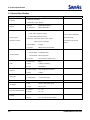
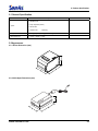
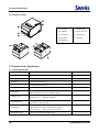
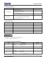
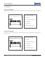
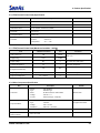
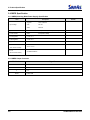
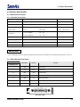
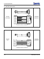
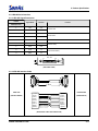

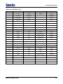

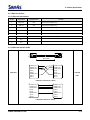
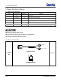


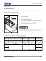

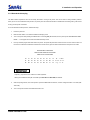

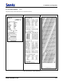

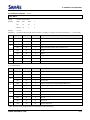

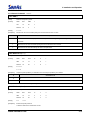
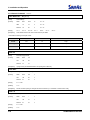


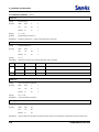
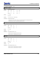
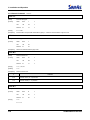
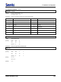
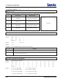
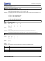
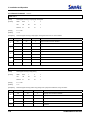
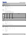
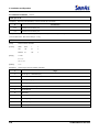

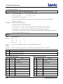
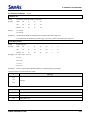
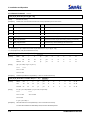


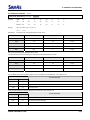


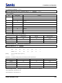

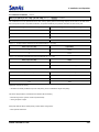
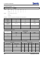


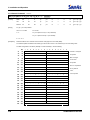
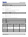


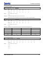
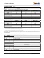
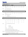

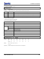
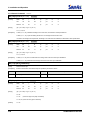
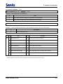

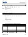

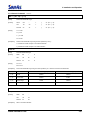


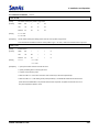
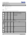
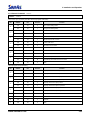

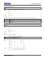
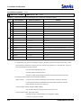


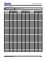
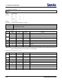
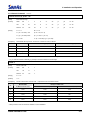
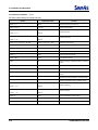
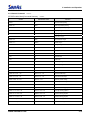
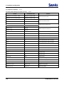
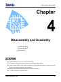

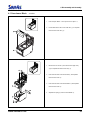

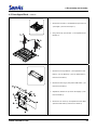
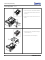
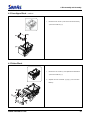
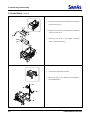
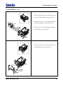

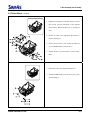


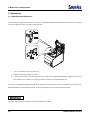
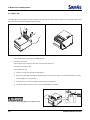


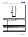

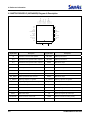

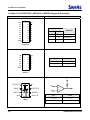


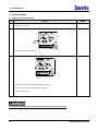
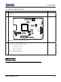

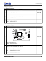
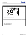
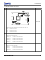


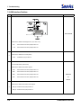
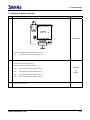

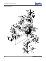
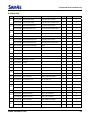
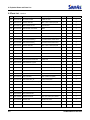

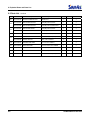
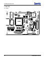
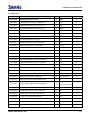

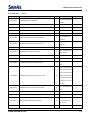
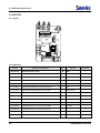

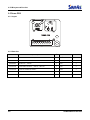
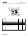
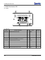

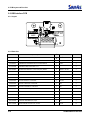
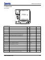


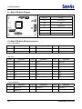

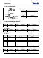
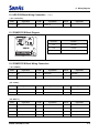


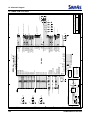
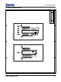
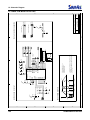
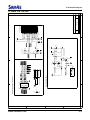


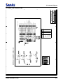
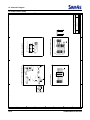
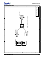
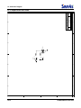


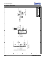
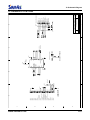


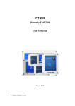
![[SPT-3000] e](http://vs1.manualzilla.com/store/data/005667089_1-a5f3766b3193f6552f250995926a69c5-150x150.png)