1
TN301
Rabbit 2000™ Microprocessor
Interrupt Problem
A problem related to the use of the external interrupt inputs was present in the logic of the original version
of the Rabbit 2000 (marked IQ2T). The problem is limited to four multiple-function pins that can be used as
external interrupt requests. The problem affects only the functionality of the interrupt requests. This technical note provides workarounds to avoid the problem.
The Rabbit 2000 has four pins (pin numbers 23, 24, 29, and 30) that can be used as external interrupt
inputs. These pins support multiple uses as I/O ports, I/O strobes, and as external interrupt inputs
(requests). If you are using the pins as I/O ports or as I/O strobes, then you do not have to worry about this
problem. Only customers who are using one or more of these pins to request an interrupt need to consider
the material here. This problem does not affect the operation of any other devices or interrupts associated with
the Rabbit 2000.
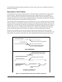
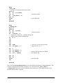
Figure 1 shows a block diagram of the external interrupt logic.
INT1A
INT1B
29
Interrupt Request #1
23
Edge
Detectors
INT0A
INT0B
30
Interrupt Request #0
24
Figure 1. Rabbit 2000 External Interrupt Logic
There are two independent interrupts that may be generated by inputs to the four pins. Each pin is connected to an edge detector that can be configured under program control to detect rising or falling edges.
These same pins, a part of parallel port E, support alternate functionality as general-purpose inputs, outputs, or I/O strobes. This alternate functionality is not affected by the problem.
A customer reported that an interrupt would be lost occasionally when one of the interrupt inputs was used
as a pulse counter, and as a result the count would be low. After an investigation, we determined that the
problem can be easily worked around when there is a need for external interrupt request lines. The
workarounds described here are compatible with correcting the problem if there should be a future revision
022-0042 Rev. C
1
of the Rabbit 2000 chip that might be undertaken for other reasons, such as the availability of improved
fabrication technology.
Description of the Problem
The problem has to do with the circuitry that clears a flip-flop that drives the output of the edge detectors
shown in Figure 1. When the edge detector detects the rising or falling edge that it is programmed to
detect, it sets this flip-flop. The intention was that the flip-flop would be cleared automatically when the
interrupt takes place. In some cases it turns out that the flip-flop is cleared when it should not be cleared. In
other cases the flip-flop is not cleared when it should be cleared.
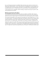
The flip-flop may be cleared spuriously because a different, lower priority, interrupt occurs nearly simultaneously (during an 8-clock window) with the occurrence of the edge that sets the flip-flop. This results in a
lost interrupt. A second problem is that the flip-flop might not be cleared when the interrupt takes place if a
different, higher priority, interrupt, is being requested nearly simultaneously (during an 8-clock window)
with the occurrence of the external interrupt. This results in a spurious interrupt after the first interrupt
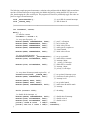
because the interrupt request was not cleared. The sequences are shown schematically in Figure 2.
In either case, the problem occurs only if an interrupt request transitions during a short time period 8
clocks long. Because the fault occurs if the transition of the interrupt request line is coincident with a very
short window, the occurrence of the fault is rare. This contributed to the fault escaping detection sooner.
Ext Interrupt Req ff
8-clock window
Spurious clear of interrupt request ff
Different lower priority interrupt
(e.g., serial port) takes place
LOST INTERRUPT
Different higher priority interrupt is
requested during 8-clock window
Ext Interrupt Req ff
External Interrupt
takes place
Request ff fails to be cleared
Spurious interrupt
results
SPURIOUS INTERRUPT
Figure 2. Interrupt Sequences with Lost or Spurious Interrupts
022-0042 Rev. C
2
By way of background, interrupts on the Rabbit 2000 can take place at three priority levels from low to
high priority, and numbered as 1, 2 and 3. Each on-chip device, including the two external interrupts, can
be assigned a priority at which interrupts will take place. For interrupts that have been assigned the same
programmed priority, there is an implicit priority with external interrupt #1 having the highest priority,
external interrupt #0 the second highest, and the remaining on-chip devices having lower priorities in the
order specified in the user manual.
Workarounds for the Problem
The workarounds presented here do not seriously affect the capability of the Rabbit 2000. The major
inconvenience for most users that need an external interrupt request is the loss of one I/O pin that could
otherwise be used as an input or output. Users who don’t need an external interrupt input are not affected.
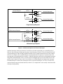
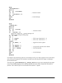
The most direct workaround is to tie the inputs for external interrupt #1 and #0 together with a 1 kΩ resistor as shown in Figure 3. If one input is needed, then two pins and one resistor are used. Using this configuration, both interrupt #1 and #0 will be requested when an edge is detected. The #1 interrupt will take
place first since it is of a higher priority. The interrupt service routine for interrupt #1 should ignore the
interrupt. The actual service routine will be the service routine for interrupt #0. If an interrupt is lost, it will
always be #1 and never #0. The 1 kΩ resistor delays the edge slightly so that interrupt #1 is guaranteed to
be latched earlier or simultaneously with interrupt #0. It is important that the programmed priority of interrupt #1 be higher than or equal to the programmed priority of interrupt #0. Normally they should be equal.
022-0042 Rev. C
3
Interrupt Request
INT1A
29
Interrupt Request #1
23
1 kΩ
Edge
Detectors
INT0A
30
Interrupt Request #0
24
Single-Interrupt Request
OR'ed Interrupt Request
INT1A
29
INT1B
23
Edge
Detectors
1 kΩ
OR'ed Interrupt Request
Interrupt Request #1
INT0A
30
INT0B
24
Interrupt Request #0
1 kΩ
OR'ed-Interrupt Request
Figure 3. Workaround Options for External Interrupts
Spurious interrupts, which occur because of a failure to clear the request latch, are a possibility only if
there are other interrupts of higher priority than external interrupt #1 and #0. These can only be the result
of programming one of the on-chip peripheral interrupts to have a higher interrupt priority. This could be
the case, for example, if the external interrupts are programmed to have priority 1, and one of the serial
port interrupts is programmed to have priority 2. Spurious interrupts can always be eliminated by programming both external interrupts to have a priority equal to the highest priority used for another device. The
priority can be reduced on entry to the service routine to avoid blocking the true high-priority interrupts.
External interrupt #1 cannot cause interrupt #0 to have a spurious interrupt or vice versa. In some cases,
spurious interrupts may not disturb function, but the fix is so simple that it is not usually worth the trouble
to analyze this possibility.
022-0042 Rev. C
4
Software
The following sample program demonstrates the problem with the Rabbit 2000 external interrupt lines.
External interrupts are triggered by the Rabbit chip itself by setting the PE0–PE7 pins as outputs, then
changing the value on those pins. This program uses Timer B to periodically toggle the values on port E to
trigger external interrupts. External interrupts will be lost because of interference by the Timer B interrupt
that occurs at the same time.
// function prototypes
void _ext0_ISR();
void _timerB_ISR();
/*****************************************************************/
int countExt0, countB;
main() {
countExt0 = countB = 0;
// initialize counters
// set up port E properly
WrPortI(PEDDR, &PEDDRShadow, 0xFF);
WrPortI(PEDR, &PEDRShadow, 0x00);
WrPortI(PEFR, &PEFRShadow, 0x00);
WrPortI(PECR, &PECRShadow, 0x22);
WrPortI(PEDR, &PEDRShadow, 0x00);
/* set up external interrupt 0 */
SetVectExtern(0, _ext0_ISR);
WrPortI(I0CR, &I0CRShadow, 0x33);
/* set up timer B B1 interrupt */
SetVectIntern(0x0B, _timerB_ISR);
WrPortI(TBCR, &TBCRShadow, 0x01);
WrPortI(TBL1R, NULL, 0x00);
WrPortI(TBM1R, NULL, 0x00);
WrPortI(TBCSR, &TBCSRShadow, 0x03);
while (countB < 1000);
//
//
//
//
//
//
port E = all outputs
initial values all zero
no I/O strobe pins
enable port E to update on
timer B match
initial values all zero
// set up external interrupt 0 vector
// enable PE4 as external interrupt 0
// input, priority 3
// set up timer B interrupt vector
// clock timer B with (perclk/2),
// priority 1
//
//
//
//
set up initial match
enable timer B and B1 match
interrupt
do nothing
/* disable all the interrupts */
WrPortI(I0CR, &I0CRShadow, 0x00);
// disable ext int 0
WrPortI(TBCSR, &TBCSRShadow, 0x00);
// disable timer B interrupt
printf(" Timer B count
= %4d\n", countB);
printf(" Ext int 0 count = %4d\n", countExt0);
}
022-0042 Rev. C
5
#asm
_ext0_ISR::
; interrupt is cleared when this function called
push hl
ld
hl, (countExt0)
inc hl
; increment counter
ld
(countExt0), hl
pop hl
ipres
; restore interrupts
ret
#endasm
#asm
_timerB_ISR::
push af
push hl
ld
hl, (countB)
inc hl
ld
(countB), hl
; increment counter
;; toggle port E output here -- external interrupt will
;; trigger on both rising and falling edges
ld
a, l
rla
rla
rla
rla
and 0xFE
; clear bit 0 (= buzzer on dev board)
ioi ld (PEDR), a
; toggle bit 4 (0,1,0,1,...)
xor
ioi
ioi
ioi
a
ld (TBL1R), a
ld (TBM1R), a
ld a, (TBCSR)
pop hl
pop af
ipres
ret
; set up next B1 match at timer=0000h
; clear interrupt flag
; restore interrupts
#endasm
A new function, SetVectExtern2000(), has been added to the Dynamic C SYS.LIB library. This
software is included starting with the Dynamic C 6.19. The code for the _ext0_ISR and
_timerB_ISR function types must be included for the sample to run. These function types are not
included in the Dynamic C upgrade.
022-0042 Rev. C
6
The following sample program demonstrates a solution to the problem with the Rabbit 2000 external interrupt lines. External interrupts are triggered by the Rabbit chip itself by setting the PE0–PE7 pins as outputs, then changing the value on those pins. This program uses Timer B to periodically toggle the values on
port E to trigger external interrupts.
// user's ISR for external interrupts
// ISR for timer B
void _extIntHandler();
void _timerB_ISR();
/******************************************************************/
int countExt0, countB;
main() {
// initialize counters
countExt0 = countB = 0;
/* set up port E properly */
WrPortI(PEDDR, &PEDDRShadow, 0xFF);
WrPortI(PEFR, &PEFRShadow, 0x00);
WrPortI(PEDR, &PEDRShadow, 0x00);
WrPortI(PECR, &PECRShadow, 0x22);
WrPortI(PEDR, &PEDRShadow, 0x00);
/* set up external interrupts */
SetVectExtern2000(3, _extIntHandler);
WrPortI(I0CR, &I0CRShadow, 0x33);
WrPortI(I1CR, &I1CRShadow, 0x33);
/* set up timer B interrupt (match register B1) */
SetVectIntern(0x0B, _timerB_ISR);
WrPortI(TBCR, &TBCRShadow, 0x01);
WrPortI(TBL1R, NULL, 0x00);
WrPortI(TBM1R, NULL, 0x00);
WrPortI(TBCSR, &TBCSRShadow, 0x03);
//
//
//
//
//
//
port E = all outputs
no I/O strobe pins
initial values all zero
enable port E to update on
timer B match
initial values all zero
//
//
//
//
//
//
//
set up vector table
enable PE4 as external
interrupt 0 input,
priority 3, both edges
enable PE5 as external
interrupt 1 input,
priority 3, both edges
// set up timer B interrupt vector
// clock timer B with (perclk/2),
// interrupt level 1
// set up initial match
// enable timer B and B1 match
// interrupt
// do nothing
while (countB < 1000);
/* disable all the interrupts */
WrPortI(TBCSR, &TBCSRShadow, 0x00);
// disable timer B interrupt
WrPortI(I0CR, &I0CRShadow, 0x00);
// disable ext int 0
WrPortI(I1CR, &I1CRShadow, 0x00);
// disable ext int 1
printf(" Timer B count
= %4d\n", countB);
printf(" Ext int 0 count = %4d\n", countExt0);
}
022-0042 Rev. C
7
#asm
_extIntHandler::
push hl
ld
hl, (countExt0)
inc hl
ld
(countExt0), hl
pop hl
ipres
ret
#endasm
; increment counter
; restore interrupts
#asm
_timerB_ISR::
push af
push hl
ld
hl, (countB)
inc hl
; increment counter
ld
(countB), hl
;; toggle port E output here -- external interrupts will
;; trigger on both rising and falling edges
ld
a, 0x01
and l
jr
z, toggle
; if bit 0 was 0, then bits 4,5 = 0
ld
a, 0x30
; if bit 0 was 1, then bits 4,5 = 1
toggle:
ioi ld (PEDR), a
; toggle bits 0 and 1 together
xor a
ioi ld (TBL1R), a
ioi ld (TBM1R), a
; set up next B1 match at timer=0000h
ioi ld a, (TBCSR)
; clear interrupt flag
pop hl
pop af
ipres
; restore interrupts
ret
#endasm
Note that the external interrupt count may occasionally be off by one in this program because of the initial
state of the port E output pins. The interrupt is missed because the edge does not change even though a
timer B match occurs.
The code for the _extIntHandler and _timerB_ISR function types must be included for the sample
to run. The assembly language code is different than the code in the earlier example that illustrated the
problem. These function types are not included in the Dynamic C upgrade.
022-0042 Rev. C
8
More on Workarounds
To simplify modification of an existing design, the 1 kΩ resistor in the circuit suggested in Figure 3 may
be omitted, but this will complicate the interrupt service routine since then there will then be a very slight
possibility that interrupt #0 will be lost, in which case interrupt #1 will not be lost.
If a system has already been designed and it would be inconvenient to modify it, then a software fix can be
considered. Interrupts will not be lost if there are no other lower priority interrupts taking place. This can
be arranged by making the external interrupt be at priority 1 and all other interrupts at priority 2 or 3. The
interrupt priority can be raised in the interrupt service routine after the interrupt takes place, if necessary.
This leaves the possibility of spurious interrupts, but usually they are not a problem because they can be
ignored by the service routine.
If more than two interrupt request inputs are needed, either an alternative input can be used, as suggested
in the next section, or the requests can be or’ed together and tied to one of the interrupt request lines.
When requests are or’ed together, there must be a way for the interrupt service routine to determine which
device needs service, for example, by reading an attention line from each device.
Alternative External Interrupt Inputs
There are a number of other inputs that can be pressed into service as external interrupt inputs. The data
inputs of the serial ports, the clock input of a serial ports A and B, or the slave port write strobe can be
used to generate interrupts in response to an external request line.
The slave port provides an alternate interrupt input (pin 95, /SWR, the slave port write strobe). Enabling
the slave port requires using the eight pins of I/O port A for data I/O and six other pins for a chip select,
two address lines, the read strobe, and the write strobe. An interrupt is generated when the write line is
strobed with the chip select and two address lines held low. I/O Port A normally serves as the slave port
data port. Data are strobed into this port on the write strobe. If it is desired to use this port as an output
while the slave port is enabled, the slave port read strobe can be held low to force continuous output from
this port (this feature has not been tested).
Any of the serial port data inputs can be used to generate an interrupt. If the input (RX) is pulled low, a
series of null characters will be received by the serial port. The interrupt routine can clear the interrupt
after the input line goes high by removing two characters that are in the registers.
The serial port clock input on serial ports A and B can be used to generate an interrupt or to count pulses.
When set up to use an external clock, the serial port assembles 8-bit characters in response to eight external clock pulses. An interrupt can be generated by a single external clock if seven pulses are fed into the
port first to arm it. The seven arming pulses can be generated by connecting a driving bit to the clock input
and toggling it seven times. (PB0, PB1 serve as clock inputs for serial ports A and B). Theses inputs are
also valuable for high-speed counting since one interrupt will be generated for every eight pulses input. If
the total number of pulses is not a multiple of eight, the number of remainder pulses can be determined by
manually adding 1–8 pulses until the next character is assembled.
022-0042 Rev. C
9
Alternatives to External Interrupts
A technique that could be described as synthetic interrupts is often a desirable alternative to a hard external
interrupt. This is done by using an interrupt routine that is driven continuously by a timer, and using that
routine to examine a number of input lines that can be considered to be interrupt requests. The synthetic
interrupt can be edge or level sensitive. When a condition is detected requiring a synthetic interrupt, the
routine calls the interrupt service routine.
This technique is more robust and requires less hardware than using hard interrupts. It is especially good
for counting pulses and can be used to count a number of input pulse streams at the same time. Experience
shows that counting pulses by using an interrupt input is an endless source of trouble because of ill-conditioning of the pulses and exceptions that often happen at the start and end of the pulse train.
Hardware interrupts can be reserved for the most time-critical situations.
Z-World, Inc.
Rabbit Semiconductor
2900 Spafford Street
Davis, California 95616-6800
USA
2932 Spafford Street
Davis, California 95616-6800
USA
Telephone: (530) 757-3737
Fax: (530) 757-3792
Telephone: (530) 757-8400
Fax: (530) 757-8402
www.zworld.com
www.rabbitsemiconductor.com
022-0042 Rev. C
10