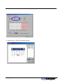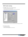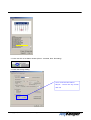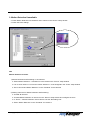
1
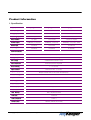
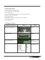
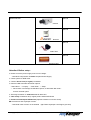
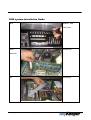
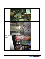
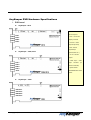
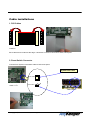
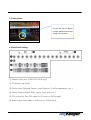
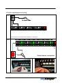
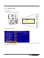
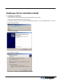
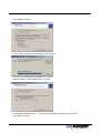
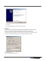
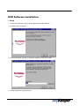
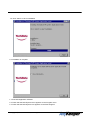
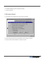
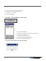
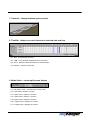
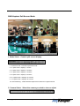
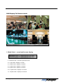
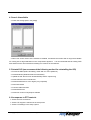
DIGITAL VIDEO RECORDER SYSTEM
AnyKeeperTM USER MANUAL
Product Information
1. Specification
Features
AnyKeeperAnyKeeper-2004
AnyKeeperAnyKeeper-2008
AnyKeeperAnyKeeper-2516
Camera Input
4 channels
8 channels
16 channels
Display Speed
120 fps
120 fps
480 fps
Recording Speed
120 fps
120fps
120fps
Video Partition
1,4 splits
1,4,7,9 splits
1,4,7,9,13,16 splits
monitor output
RGB(VGA), Composite
RGB(VGA), Composite
RGB(VGA), Composite, SVHS
Sensor input
4 channels
16 channels
16 channels
Alarm output
4 channels
8 channels
8 channels
Common Features
Video Resolution
640 x 480, 640 x 240, 320 x 240
Quality Control
5 Levels of controlling
Size of image
2-4KB(320x240, Medium Level)
H.263 Compression Algorithm
Video Compression
Screen switching
1 - 10 seconds
Output resolution
Over 400 TV Line (I screen)
PlayBack Display
Multiple camera views on the screen simultaneously
Local / Web camera
Web Camera support
Network
LAN, Cable Modem, ISDN, PTSN, PPP(Dial up)
Alarm output time
1 second - unlimted time selection
Motion Detection
5 Types of sensors
Power tolerance
Supported
AutoAuto-detection
Supported
Back-up
Data Back
DVD, JAZ, Network Drive
Audio input
Audio compression
Remote control
Copyright ⓒ 2001 TechData Co., Ltd. All rights reserved.
4 channels
H.723-1
RS232C (PAN/Tilt/Zoom/IRIS)
2. System requirements
●
O/S : Microsoft Windows 98 , ME, 2000
●
CPU : Intel Pentium Ⅲ 500MHz or higher
●
RAM : 128MB or higher
●
VGA : ATI Compatible AGP Graphic Card, VIP(Video Input Port) Existence
●
Resolution : 1024 × 768, 32bit Color
●
HDD : 30GB or greater
●
Backup Storage : CD R/W, Tape Backup System, DVD-RAM, etc
●
S/W : Direct X 8.0 or later
●
Driver : DVR Driver
3. DVR System Structure
DVR System User Manual
Manual
Included
DVR System Capture Board
Included
DVR System Cables
Included
Included
DVR System Back Panel
(2008, 2016,2516 only)
Included(2004 only)
Input/output
Audio
Copyright ⓒ 2001 TechData Co., Ltd. All rights reserved.
Optional Devices
Optional
Camera
Optional
Detector
Optional
Audio Siren
Optional
Warning Light
Attention! Before setup :
●
Please check the power supply is the correct voltage.
: Most DVR components use 220V compliant Power Supply.
●
Check system for DVR driver
●
Check if Direct X 8.0 (or higher) is installed
●
Remove HDD Automatic Disk clean options
: Select Drive → Property → Disk Clean → Setup
→ “When there is a shortage of HDD Drive space, do automatic disk clean”
remove checked option
●
Set image resolution to 1024×768 mode & 32bit color
●
Clear setup of Windows 98 (or higher) before install DVR Board
●
Do Not use VIA Chipset Mainboard (Optimal condition in Intel 81x series)
● Check driver and Anykeeper version.
: Download newer version on the website
(http://www.anykeeper.com/support_02.html)
Copyright ⓒ 2001 TechData Co., Ltd. All rights reserved.
DVR system Installation Guide
Open
Remove
back,
side screws.
Install
Into PCI slot.
DVR board
DIO
Copyright ⓒ 2001 TechData Co., Ltd. All rights reserved.
Connecting
Audio
Connect
Watch-dog
Switch
cable
conecting
Copyright ⓒ 2001 TechData Co., Ltd. All rights reserved.
AnyKeeper DVR Hardware Specifications
1. DVR board
!
Anykeeper - 2516
* Audio – 4channels to
the microphone
* Gain – Control the
display constrast
* VIP Port – Video
Input Port(to VGA)
* DIO – Device
Input/Output
!
AnyKeeper – 2008, 2016
(sensor,alarm etc..)
* TV out – Monitor
output
* Video Input – video
input
connector
(to
Camera channels)
* System Reset
cable/Mainboard Reset
Cable
!
AnyKeeper – 2004
Copyright ⓒ 2001 TechData Co., Ltd. All rights reserved.
Cable installations
1. DIO Cables
Caution!!
Each cable has a red lane at the edge. It should be connect to connector’s white, bold square.
2. Reset Switch Connector
Connect from System reset-switch cable to DVR reset panel
System Reset cable
Reset cable
<DVR 보드>
Reset switch
<Main Board>
Copyright ⓒ 2001 TechData Co., Ltd. All rights reserved.
3. Control Gain
Change this gain for display
contrast (default manufacture
setting is changeable!)
4. Back Panel Setting
① Camera Input port (2008 2016 2516 only)
② TV monitor Input port
③ Device Input (Infrared Sensor, Heat Detector, Fire Reorganization, etc..)
④ Device Output (Alarm, Alert, Lamp, Door lock, etc..)
⑤ DIO connector (thru DIO cable to DIO port on DVR board)
⑥ Video output (thru cable to VGA port on DVR board)
Copyright ⓒ 2001 TechData Co., Ltd. All rights reserved.
5. Device Input/Output Connecting
Sensor
To Power Cable
S1 S2 S3 S4 G S5 S6 S7 S8 G S9 S10 S11 S12 G S13 S14 S15 S16 EX GN EX 12V
G
12V
From left side, the number have an arranged 1~16 devices.
Alarm
NC C NONC
NONC C NONC
NONC C NO
NONC
NC C NONC
NONC C NONC
NONC C NONC
NONC C NONC
NONC C NO
1
2
3
4
5
6
7
8
12 G
V R
D
Output device connection
Copyright ⓒ 2001 TechData Co., Ltd. All rights reserved.
TIP! JUMPER SETTINGS
1. Basic Settings
Ex) Normal Intel chipset using main board
Except
RESET
switch,
All
connection will be the same
as main board manual settings
2. Power-On after power-fail
- There is the PWRON After PWE-Fail in the BIOS setup. Such function will have the PC system powered
on automatically after the power failure.
Copyright ⓒ 2001 TechData Co., Ltd. All rights reserved.
AnyKeeper Driver Installation Guide
1. AnyKeeper installation
●
With computer turned off, install Anykeeper DVR Board in any PCI slot.
●
Power On and start with Windows 98 (or higher)
●
Anykeeper supports PnP, the system will detect DVR board as a PCI multimedia Device as shown
below (in windows 2000)
PCI Multimedia Device
●
found New Hardware
●
Click NEXT to continue
●
Search for a suitable driver for device (recommended)
Copyright ⓒ 2001 TechData Co., Ltd. All rights reserved.
●
Click Next to continue
●
check Specify a location (for forwarding to driver folder)
●
The driver for Anykeeper is in the directory “c:\dvrdrv”
●
Before installing, extract DVR drivers in c:\dvrdrv
C:\dvrdrv\capture.inf
●
It will display “Capture board…..” in sound, video and game controllers of your system
●
Click Next to continue
Copyright ⓒ 2001 TechData Co., Ltd. All rights reserved.
●
Click “finish”
●
After installing DVR board in your system, please restart.
Attention :
First of all, before reinstall the driver for DVR, delete existing two driver files as below,
Files are on C:\winnt (or windows)\system32\drivers\ [cap01.sys & cap02.sys]
If the DVR board is already installed, occasionally the driver will need to be reinstalled manually.
In this case, update the following way: [Control panel]-[System]-[Device manager],
Click “Reinstall Driver….”
Then follow the same method as above.
Copyright ⓒ 2001 TechData Co., Ltd. All rights reserved.
DVR Software Installation
1. Setup
1-1. Insert DVR Application Disk in Floppy Drive or CD-ROM, Network…
1-2. Double Click on Install file
1-3. Choose the folder you wish to install this software to and click "Install"
1-4. setup complete and system reboot
Copyright ⓒ 2001 TechData Co., Ltd. All rights reserved.
1-5. Click "Abort" to cancel installation
1-6. Installation is complete
1-7. Run DVR Application software
1-8. Check that the DVR System menu appears on the Program menu
1-9. Check that the DVR System icon appears on the Start Program
Copyright ⓒ 2001 TechData Co., Ltd. All rights reserved.
1-10. Software installation has been completed successfully
1-11. Remove Install disk
2. DVR software Reinstall
2-1. Pay attention when deleting data files during program reinstallation
2-2. Previous data files will be removed automatically if “No more Query” is selected
2-3. Follow the steps for initial installation to complete the process
Copyright ⓒ 2001 TechData Co., Ltd. All rights reserved.
3. DVR Software Uninstall
3-1 Run Uninstall in the DVR system Folder
3-2. Click “Yes” to uninstall
3-3. Click "Ok"
3-4. The software has been successfully uninstalled
Copyright ⓒ 2001 TechData Co., Ltd. All rights reserved.
DVR Control Panel
1. Information: displays date & other system information
2. Access : control recording, motion sensors, alarms, setup, network, and Web-Cam
2-1. Record : Recording status
2-2. Motion : Motion detection status
2-3. Alarm : Alarm status
2-4. Setup : configure system settings
2-5. Network : To access network
2-6. WebCam : Configure Web-Cam settings(still not supported)
Copyright ⓒ 2001 TechData Co., Ltd. All rights reserved.
3. Adjust: adjust the color and brightness settings
3-1. Brightness: adjust Brightness
3-2. Contrast: adjust Contrast.
3-3. Saturation: Control degree of difference from a gray of the same
lightness or brightness.
3-4. Hue: adjust Hue
※Hue : The property of colors by white they can be perceived as
ranging from red through yellow, green, and blue, as determined
by the dominant wavelength of the light
3-5. Default: restores settings to default setup mode
※ only applies to the selected camera
4. PTZ : adjust Pan / Tilt / Zoom for the selected camera
4-1. Zoom: select Zoom In or Out
4-2. IRIS: select IRIS In or Out
4-3. FOCUS: select FOCUS In or Out.
4-4. ▲▼◀▶ : select direction
※ only applies t o the selected camera
Copyright ⓒ 2001 TechData Co., Ltd. All rights reserved.
5. Tabmode : change between system panels
6. Camera Select : select the camera you wish to view or adjust
※ only applies to the camera selected
7. Mode Select: control the split screen mode
7-1. Full screen mode: displays full screen
7-2. 1 split mode: display one screen
7-3. 4 splits mode: displays 4 screens
7-4. 7 splits mode: displays 7 screens
7-5. 9 splits mode: displays 9 screens
7-6. 13 splits mode: displays 13 screens
7-7. 16 splits mode: displays 16 screens
7-8. Auto Switching: rotates between split screen modes at a regular interval
Copyright ⓒ 2001 TechData Co., Ltd. All rights reserved.
8. Power: Close Application
※ To close the application either use the power button or System Shut Down in the Setup mode.
Copyright ⓒ 2001 TechData Co., Ltd. All rights reserved.
DVR Status Panel
1. Information: displays date & other system information
2. Recording Camera: display the status of each camera
2-1. Gray : indicates an inert camera
2-2. Green : indicates an active camera
Copyright ⓒ 2001 TechData Co., Ltd. All rights reserved.
2-3. Red : indicates a camera is recording
※ Indicator lights start at camera 1and move to the right then down to camera 16
3. Sensor Detect: displays the status of detection sensors
3-1. Gray : indicates an inert sensor
3-2. Green : indicates an active sensor
3-3. Red : indicates a sensor has been activated
※Indicator lights start at camera 1and move to the right then down to camera 16
4. Motion Detect: displays the status of motion sensors
4-1. Gray: indicates an inert motion sensor
4-2. Green: indicates an active motion sensor
4-3. Red: indicates a sensor has been activated
※Indicator lights start at camera 1and move to the right then down to camera 16
5. Alarm: displays the status of Alarms
5-1. Gray : indicates an inert alarm
5-2. Green : indicates an active alarm
5-3. Red : indicates an alarm has been activated
※Indicator lights start at alarm 1 and move to the right to alarm 8
6. HDD Capacity: displays current HDD capacity
Copyright ⓒ 2001 TechData Co., Ltd. All rights reserved.
7. Event: displays information for each event in the system as hey occur
※ displays all system activities
(example: system start, shutdown, recording, alarm activation, etc)
Copyright ⓒ 2001 TechData Co., Ltd. All rights reserved.
8. Event Log : records all system events
8-1. To open click "Event log"
8-2. Date: select the date you wish to view
8-3. Event List : displays all event information for the
selected date
8-4. Refresh : refreshes the screen
8-5. Exit : closes EventLog Dialogue Box
8-6. Delete : delete selected event
8-7. Delete All : delete all events for the selected date
9. Tabmode : change between system panels
Copyright ⓒ 2001 TechData Co., Ltd. All rights reserved.
10. Camera Select: select the camera you wish to view or adjust
※ view event log for one camera at a time
11. Mode Select: control split screen display
11-1. Fullscreen mode: displays full screen mode
11-2. 1 split mode: displays one screen
11-3. 4 splits mode: displays 4 screens
11-4. 7 splits mode: displays 7 screens
11-5. 9 splits mode: displays 9 screens
11-6. 13 splits mode: displays 13 screens
11-7. 16 splits mode: displays 16 screens
11-8. Auto Switching: rotates between split screen modes at a regular interval
12. Power : Close application
Copyright ⓒ 2001 TechData Co., Ltd. All rights reserved.
DVR Search Panel
1. Information: displays date & other system information
2. Play Control
Copyright ⓒ 2001 TechData Co., Ltd. All rights reserved.
2-1. ◀◀: Fast backward.
2-2. ◀: Backward
2-3. �: Stop
2-4. ▶: Play
2-5. ▶▶: Fast forward
2-6. ∥◀: move to the start of the recording period
2-7. |◀: move back one frame
2-8. ♠: move the place of event conducting
2-9. ▶|: move forward one frame
2-10.▶∥: move to the end of the recording period
3. Zoom & Brightness: control zoom in/out & brightness of recorded images
3-1. Zoom : adjust zoom in/out
3-2. Brightness : adjust brightness
3-3. Default : reset to the default settings
4. Zoom & Brightness: edit, save, and print recorded images
4-1. Blur : soften the selected image
4-2. Sharp : sharpen the selected image
4-3. Normal : reset to the default settings
4-4. Save : save an image as a BMP or AVI file
Copyright ⓒ 2001 TechData Co., Ltd. All rights reserved.
4-5. Print : print out selected image
4-6. Backup : backup recorded data to an alternate storage device
Copyright ⓒ 2001 TechData Co., Ltd. All rights reserved.
4-6-1. Date : select the period for data to be backed up
4-6-2. Target Drive : select backup drive location
4-6-3. Start Backup : Start Backup
4-6-4. Close : Close Backup
5. BookMark : make a BookMark of recorded image
5-1. To Open click "BookMark"
5-2. BookMark List: displays the date and time of the BookMark
5-3. Add: add selected Bookmark
5-4. Delete: deleted selected Bookmark
5-5. Delete All: delete all Bookmarks in the list
5-6. Ok: close the BookMark dialogue box
6. Calendar : Select a date to view recorded images
Copyright ⓒ 2001 TechData Co., Ltd. All rights reserved.
7. Tabmode : change between system panels
8. TimeBar : display recorded videos for a selected date and time
8-1. ▲▼ : scroll through cameras
8-2. ◀▶ : move forward or backward on the time line
8-3. Zoom : adjust the time intervals for the selected date
8-4. Refresh : refresh the Time Bar
9. Mode Select : control split screen display
9-1. Full screen mode : converts to full screen mode
9-2. 1 split mode : displays 1 screen
9-3. 4 splits mode : displays 4 screens
9-4. 7 splits mode : displays 7 screens
9-5. 9 splits mode : displays 9 screens
9-6. 13 splits mode : displays 13 screens
9-7. 16 splits mode : displays 16 screens
Copyright ⓒ 2001 TechData Co., Ltd. All rights reserved.
10. Power: Close Application
Copyright ⓒ 2001 TechData Co., Ltd. All rights reserved.
DVR Capture Full Screen Mode
1. Mode Select : Control split screen display
1-1. Restore mode : converts to previous mode.
1-2. 1 splits mode : displays 1 screen
1-3. 4 splits mode : displays 4 screens
1-4. 7 splits mode : displays 7 screens
1-5. 9 splits mode : displays 9 screens
1-6. 13 splits mode : displays 13 screens
1-7. 16 splits mode : displays 16 screens
1-8. Auto Switching : rotates between split screen modes at a regular interval
2. Camera Select : Select the camera you wish to view or adjust
※ You can only select one camera for full screen mode
Copyright ⓒ 2001 TechData Co., Ltd. All rights reserved.
DVR Replay Full Screen mode
1. Mode Select : control split screen display
1-1. Restore mode : converts to previous mode
1-2. 1 split mode : displays 1 screen
1-3. 4 splits mode : displays 4 screens
1-4. 7 splits mode : displays 7 screens
1-5. 9 splits mode : displays 9 screens
1-6. 13 splits mode : displays 13 screens
1-7. 16 splits mode : displays 16 screens
Copyright ⓒ 2001 TechData Co., Ltd. All rights reserved.
2. Play Control
2-1. ◀◀ : Fast backward.
2-2. ◀ : Backward
2-3. � : Stop
2-4. ▶ : Play
2-5. ▶▶ : Fast forward
2-6. ∥◀ : move to the start of the recording period
2-7. |◀ : move backs one frame
2-8. ♠ : move to the time of the event occurrence
2-9. ▶| : move forward one frame
2-10.▶∥ : move to the end of the recording period
Copyright ⓒ 2001 TechData Co., Ltd. All rights reserved.
DVR system Setup mode
1. System Setup
1-1. System location: select the name of the system you wish to use
1-2. Auto Switching Interval: select the time period for auto switching
1-3. Power On/Off: select this option to shut the computer down when closing this application
1-4. Display Channel Text: turn channel information display on/off
1-5. Video Signal Type: select video input signal
1-6. Hard Disk Usage: set HDD user mode
-
Once : Write HDD just one time and appear error message
-
Recycle : If HDD is getting full, Remove last day data
Copyright ⓒ 2001 TechData Co., Ltd. All rights reserved.
1-7. Storage Management: select the folder you wish to save , replay data
<Recording Path selection>
-
Forward to capable Hard disk.
-
Select Directory Name to make
<Replaying Path selection>
1-8 Network Transfer Image Type
1-8-1. Still Image: get better quality of image instead of bigger image size
(Recommended fast link network)
1-8-2. Motion Image: get smaller size image instead of worse quality image
(Recommended slow link network)
1-8-3. Network Transfer Image Quality : to control changing image quality
Copyright ⓒ 2001 TechData Co., Ltd. All rights reserved.
1-9. Set Password
1-9-1. On Setup: confirm Password on setup
1-9-2. On Recoding Stop: confirm Password on recording stop
1-9-3. On Shut Down: confirm Password on system shut down
1-9-4. Change Passwords
1-9-5. User Level: select user level
1-9-6. Current Password: input current password
1-9-7. New Password: input new password
1-9-8. Confirmation: input new password again
1-9-9. Ok
1-9-10. Cancel
2.Device Setup
2-1-1. Camera: Select Camera to configure
2-1-2. Activation: set recording to on/off
2-1-3. Resolution: select the desired resolution for each camera
Copyright ⓒ 2001 TechData Co., Ltd. All rights reserved.
2-1-4. Quality: select the quality require for compressed images
2-1-5. Speed: select the desired recording speed
2-2-1. Motion Activation : set motion detect to on/off
2-2-2. Sensitive: select the desired sensitivity for motion sensors
2-2-3.Zone : select the active detection zone
- in the setting zone, point to secured area to
need.
2-4.
Pan/Tilt/Zoom
2-4-1. Port :
select connecting COM port.
2-4-2. Baud Rate :
Select Baud Rate
2-4-3. Date Bits :
Select data bits
2-4-4. Parity :
Select Parity bits
2-4-5. Stop Bits : select stop bits
2-4-6. Flow : select Flow control
Copyright ⓒ 2001 TechData Co., Ltd. All rights reserved.
2-5 Alarm
2-5-1. Alarm Activation
2-5-2. Event Latency Time : control to how long alarming time.
2-6. Sensor
2-6-1. Activation : sensor activation
2-6-2. Type :
NC(Normal Close-closed generally)
NO(Normal Open-alarming when closed)
Copyright ⓒ 2001 TechData Co., Ltd. All rights reserved.
2-7. Audio
2-7-1. Activation
2-7-2. Camera Selection
point to recordable Camera
3. Event
ex1) Sensor 1 – Recording Link 1 – Alarm
Link 1 – Alert 1
: token image or signal was recorded to 1
camera and alarming alarm 1, ring alert
ex2) sensor 3 – Recording Link 2 –Alarm
Link 4 – Alert (no tic)
:token image or signal was recorded to
camera 2 and alarming alarm 4.
Copyright ⓒ 2001 TechData Co., Ltd. All rights reserved.
4. Schedule
1. select camera
2. mark to record or motion detect and integrate record with caught motion.
Ex) Camera 1 has to record when sensor 2 is detected from PM 3:00~AM 12:00
Copyright ⓒ 2001 TechData Co., Ltd. All rights reserved.
3. Holiday setting : schedule to irregularly settings
Copyright ⓒ 2001 TechData Co., Ltd. All rights reserved.
DVR Trouble shooting
1. NO SIGNAL or Blue screen on display window
●
check camera connection and power supply
●
check the activation box for each camera on the “Setup” menu (shown below)
●
restart DVR application (You should always restart Anykeeper when applying new settings).
2. Recording Unavailable
●
Check the camera is activated
●
Check the “Recording Stopped” time in the Event Log
Copyright ⓒ 2001 TechData Co., Ltd. All rights reserved.
●
Check the LED in the Status window (Green : activated, Red : Recording)
●
Check the storage setting
Once : record one time until full
Recycle : remove first day records
when full
Copyright ⓒ 2001 TechData Co., Ltd. All rights reserved.
3. Motion Detection Unavailable
●
Check Motion Detection is activated for each camera in the “Device” setup window
●
Check the Zone settings
NB:
Motion Detection scenario
1) Motion Detection and Recording on all cameras:
●
Select Motion Detection – Activation for each camera in the “Device” setup window
●
Link to each camera 1~16 from the motion detection 1~16 as assigned in the “Event” setup window
●
Set to “Record and Motion Detection” in the “Schedule” for all cameras
2) Setting camera 3 for Motion Detection and Recording:
●
Activate all cameras
●
Activate Motion Detection on camera 3 in the “Device” setup window and configure the zone
●
In “Event” – “Motion Detection” select camera 3 as the “Recording Link”
●
Select “Motion Detection” in the “Schedule” for camera 3
Copyright ⓒ 2001 TechData Co., Ltd. All rights reserved.
4. Search Unavailable
●
Check the storage path in the [setup]
●
When new a new version of the software is installed, sometimes the old files will no longer be available
for viewing due to slight alterations in the compression algorithm.
It is recommended that all existing DVR
files and drivers be removed before installing new versions of the software.
5. Reinstall O/S (we recommend the following method for reinstalling the O/S)
●
Format the HDD (before formatting, divide with 2 or more partitions)
●
Install Windows (Windows 2000 recommended)
●
Update the INF files for main board’s BIOS (if INTEL chipset only)
●
Install VGA and sound card drivers
●
Install the MS Direct X 8.0 or higher (very important)
●
Insert DVR board
●
Connect cables and fans
●
Install DVR drivers
●
Install new version of Anykeeper software
6. No response to PTZ controls
●
Check the PTZ connections
●
Check PTZ support is selected in the setup menu
●
Check PTZ settings in the setup system
Copyright ⓒ 2001 TechData Co., Ltd. All rights reserved.
7. Network access unavailable
●
Unknown Host: Check the Server’s IP address (on prompt windows, using ‘IPCONFIG’)
●
Incorrect password: Check the password (factory default password is ‘guest’)
●
Admin: Already logged on as administrator
Copyright ⓒ 2001 TechData Co., Ltd. All rights reserved.