1
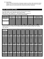
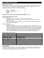
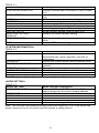
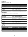
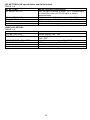
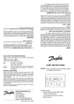
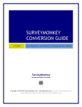
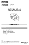
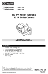
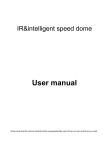
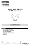
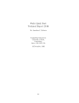
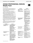
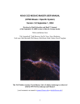
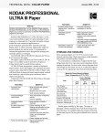
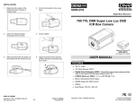
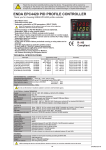
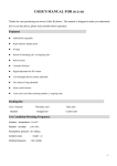
SS10W-C100H
10x Mini PTZ Camera
USER MANUAL
FEATURES
•
•
•
•
•
•
•
•
•
1/2.8” Sony CMOS CCD, 1000 TV Lines
10x Optical Zoom, 10x Digital Zoom (Max 100x Zoom)
5~50mm focal length
0.01 lux (color) / 0.001 lux (B&W)
360° Endless Pan ; 180° Auto-flip Tilt ; 95° Normal Tilt
256 Presets ; RS-485 Communication
Pelco-D & Pelco-P Selectable protocols
Built-in OSD
12V DC
P lease read the M anual before attempting to use this product.
Specifications and appearance are subject to change without notice.
Copyright © 2015 by OKINA USA. All Rights Reserved.
** Replacing SS10W-C65H
P-048
R201502-V26
Disposal of Old Electrical & Electronic Equipment (Applicable in the European
Union and other European countries with separate collection systems).
This symbol on the product or on its packaging indicates that this product shall not be treated as
household waste. Instead it shall be handed over to the applicable collection point for the recycling
of electrical and electronic equipment. By ensuring this product is disposed of correctly, you will help
prevent potential negative consequences for the environment and human health, which could
otherwise be caused by inappropriate waste handling of this product. The recycling of materials will
help to conserve natural resources. For more detailed information about recycling of this product,
please contact your local city office, your household waste disposal service or the shop where you
purchased the product.
CAUTION
1. Never point the camera toward the sun
Do not expose the lens directly to the sun or to strong light as this may damage the
pick-up device.
2. Handle this camera with care
Avoid any shock or bumping of the camera. Improper handling could damage the
camera.
3. Requires a proper operating environment
The wall mount camera is designed for outdoor use. The allowable temperature range
for operation is between -22°F ~ 122°F / -30°C ~ 50°C.
4. Clean the front face or lens
It is recommended that the surface be cleaned every 3~6 months. Cleaning should be
done by using a chamois, a very fine soft cloth, lens tissue, or cotton tipped applicator
and ethanol to carefully remove any fingerprint or dust.
5. Check the power source voltage
The power source voltage should be within the specified range. (Camera must meet
the specifications). Camera must be connected to a surge protector at all times.
6. Objects and liquid entry
Never push objects of any kind into this camera as this may touch dangerous voltage
points of short out parts that could result in a fire or electric shock. Never spill any kind
of liquid on the video product.
2
7. Servicing
Do not attempt to service this video product by yourself as opening or removing
covers may expose you to dangerous voltage or other hazards. Refer all service to
qualified servicing personnel.
8. Damage requiring service
Unplug this video product from the wall outlet and refer service to qualified servicing
personnel under the following conditions:
a. When the power supply cord or plug is damaged.
b. If liquid has been spilled, or objects have fallen into the video product.
c. If the video product has been exposed to rain or water.
d. If the video product has been dropped or the cabinet has been damaged.
e. When the video product exhibits a distinct change in performance.
LIMITED WARRANTY
OKINA USA products are covered under warranty for one year from the date of
purchase. The warranty will automatically be voided if any of the following occurs:
1. Camera sticker is removed
If the camera sticker is removed, we will not be able to confirm any information
regarding when and where the product was purchased. We have no other way to
verify the purchase record without the serial number on the camera sticker; therefore,
it should not be removed.
2. Camera is modified in any way
If the camera is scratched, damaged, or modified in a manner not described in this
manual, the warranty will be voided immediately. It is the customer’s responsibility to
keep the camera in good condition.
3. Video or power cable is cut
The video cable and the power cable should not be tampered with. Cutting or
modifying of the cables will result in termination of the warranty.
3
INDEX
FEATUERS ……………………………………………………………………………………. 1
CAUTIONS ………………………………………………………………………………….. 2-3
LIMITED WARRANTY ……………………………………………………………………….. 3
PACKAGE CONTENTS ……………………………………………………………………… 5
DIMENSIONS ……………………………………………………………………..………...... 6
FUNCTION DESCRIPTION ………….……………………………………………………. 7-9
DIP SWITCH SETTING …………………………..………………………………………..... 9
OSD SETTING …………………………………………………………..………………. 10-15
POWER-ON SELFT-TEST …………………….………………….……............. 10
PRESET POINT SETTING & CALLING ………………………………….…….. 10
PRESET POINT FUNCTION TABLE ………………….……………………….. 10
<MAIN MENU>…………………………………………………………..…..... 10-11
<SYSTEM INFORMATION> ………………………………..…………………… 11
<ADDR SETTING> ……………………………………………..………………... 11
<MOTION> ………………………………………………………...........……….. 12
<SET FRAME SCAN>…………………………………………….……………… 12
<POWER UP> ...................…………….……………….…………….……........ 13
<PARK ACTION> ........…….…………………….………………...................... 13
<PATTERNS> .......…….…………………….…………………….…..………… 13
<PROGRAM PATTERN> ......…….…………………….……………………..… 14
<CAMERA> ......…….……………….……….…………………….……………… 14
<CRUISE> ....…….…………………….…………………….……….......……… 14
<IR SETTING> ...…….…………………….…………………….………………. 15
<DISPLAY SETUP> ....…….……………….…………………….………………. 15
TROUBLE SHOOTING & MAINTENANCE …………………………….......…….…. 15-16
SPECIFICATION ……………………………………………………………...…………….. 17
4
PACKAGE CONTENTS
•
•
•
•
•
•
One (1) 10x Mini PTZ Dome Camera
One (1) Mounting Base
Three (3) Mounting Base Screws
Three (3) Thread Connector Screws
One (1) Thread Connector
One (1) User Manual
Options:
Pendant Pole Bracket
MB-CP10C
L Type Wall Mount Bracket
MB-CW1C
Arm Type Wall Mount Bracket
MB-CWA10C
For any returns, please include all components listed above with original packaging in
Resalable Condition. Absolutely No Returns will be accepted if any component is
missing and/or damaged.
5
DIMENSIONS
With Optional Brackets:
6
FUNCTION DESCRIPTION
1.
Set Address Coding, Baud Rate, Control Protocol
Any operation commands the camera has its own objectives address coding,
baud rate, control protocol, a single camera only to respond with its own address
coding, baud rate, control agreement under the operation of the command.
Camera address coding, baud rate, control protocol specific settings please refer
to the DIP settings.
2.
Target Tracking
Users can use the controls on the keyboard joystick control of the upper and
lower turning left and right cameras can be used to track moving targets or
moving horizon, while the focal length can be adjusted to change the perspective
of the size or the target image size. In the auto-focus of the state, with the lens
rotation, the camera will automatically adjust according to a rapid scene changes,
instantly get a clear picture.
3.
Focal Length / Speed Automatic Matching Technique
Manual adjustment, the longer the focal length of the case, a reflection of
high-speed ball machine makes a slight touch screen joystick may move back,
resulting in data loss. Based on user-friendly design, intelligent ball according to
the proximity of the focal length of the camera automatically adjusts the
horizontal and vertical speed, so that manual operation is more simple and easy
to track targets.
4.
Auto Turn Over
The operator will pull the bottom of the lens (vertical) after it is still holding down
the joystick, this time the level of the lens auto-rotated 180 ° turning up
immediately after the 90 °, can directly watch the back of the scene in order to
achieve the full 180 ° continuous vertical surveillance.
5.
Set and Call Preset Position
Preset function is the current state of the ball under the PTZ function of the
horizontal angle, tilt angle and camera lens focal length, etc. position parameters
stored in memory, you need to call these parameters can be quickly and
PTZ cameras will be adjusted to that location. The operator can quickly and
easily by controlling the keyboard, infrared controller, control equipment such as
storage and call the preset point, the ball machine to support 256 preset points.
6.
Lens Control
(1) Zoom Control
Users can control the keyboard or through the ball machine to adjust the focus of
the distance matrix of the host, receive the necessary panoramic images, or is a
fine view.
(2) Focus Control
System default auto-focus, zoom, the camera lens will be the center of the
screen features auto-focus, to maintain a clear picture; in exceptional
circumstances, the user can manually focus, achieve the desired image effect.
When in manual focus state, to restore the auto-focus, as long as the sway bar
can be restored remotely auto-focus. There is also a dedicated control
commands can be issued or to call an arbitrary way of restoring a preset bit
auto-focus.
7
The camera lens in the following situations will not autofocus on the camera
objectives:
a. Target is not to screen center;
b. Targets the same time in the far and near the place;
c. Target light objects, such as neon lighting, spotlights and other luminous
objects;
d. Target with droplets or dust behind the glass;
e. Targets moving too fast;
f. Large area targets, such as walls;
g. Objectives are too dark or inherently ambiguous.
7.
Aperture Control
Users can control the keyboard to manually adjust the aperture size to get the
required picture brightness.
8.
Auto Backlight Compensation
When the backlight compensation function is open, the camera lens in the light
background can be automatically targets the more the dark luminance
compensation. On the bright background light adjustment, to avoid the
background brightness caused by a mass of light throughout the picture, goals
and not identifiable because of the darkness to gain a clear image.
9.
Auto White Balance
According to the changes in ambient light, automatic adjustment, the true color
reproduction.
10. Night Vision Function (Color / Monochrome Conversion)
Cameras with night vision function, automatic color / monochrome conversion
mode, in accordance with changes in ambient light automatic conversion CCD
illumination. Such as: adequate lighting during the day due to the use of general
illumination to ensure colorful images. In the night illumination can be
automatically changed to black and white images show a clear interest.
11. Cruise
Can be pre-set cruise preset point, certain preset points, organized in the order
required to auto-cruise in the queue, only an external command can be in an
indoor speed ball set automatically according to preset points in order to provide
the time interval constant movement back and forth.
12. Pattern Scanning
Pattern scanning machines to run the ball through the menu, the trajectory is
stored down by power-on action, free movement, alarm linkage, etc. to call the
stored scan line.
13. Continuous Scan
Just an external command or through a power-on action, free movement, alarm
linkage, etc. to call, can make the ball machine horizontal direction to a certain
speed the cycle of continuous scanning.
14. Batch Scanning
Just an external command or through a power-on action, free movement, alarm
linkage, etc. to call, can make the horizontal direction the ball machine cycle of a
certain speed intermittent scan.
8
15. Area Scan
Just an external command or through a power-on action, free movement, alarm
linkage, etc. to call, can make the ball machine horizontal direction to a certain
speed, within the limits set by the community and from scanning.
DIP SWITCH SETTING
Four DIP switch is the baud rate and the control protocol switch.
Eight DIP switch is the address code setting switch
DIP switch to “ON” means to “1”, DIP switch to "OFF" means "0".
The baud rate and control protocol as the following table:
No.
1
2
3
4
Baud Rate
OFF
OFF
PELCO-P
Control
ON
OFF
PELCO-D
Protocol
OFF
ON
PELCO-D/P
ON
ON
PELCO-D/P
(BPS)
OFF
OFF
9600
ON
ON
9600
OFF
ON
4800
ON
OFF
2400
8-bit DIP switch is used to set the dome camera address coding. Address set binary
mode can be set to a total of 256 different dome camera address coding, see coding
table address.
Camera
Address
0
1
2
3
4
5
6
7
8
9
10
11
12
1
OFF
ON
OFF
ON
OFF
ON
OFF
ON
OFF
ON
OFF
ON
OFF
2
OFF
OFF
ON
ON
OFF
OFF
ON
ON
OFF
OFF
ON
ON
OFF
Camera Address Coding Form
3
4
5
6
OFF
OFF
OFF
OFF
OFF
OFF
OFF
OFF
OFF
OFF
OFF
OFF
OFF
OFF
OFF
OFF
ON
OFF
OFF
OFF
ON
OFF
OFF
OFF
ON
OFF
OFF
OFF
ON
OFF
OFF
OFF
OFF
ON
OFF
OFF
OFF
ON
OFF
OFF
OFF
ON
OFF
OFF
OFF
ON
OFF
OFF
ON
ON
OFF
OFF
7
OFF
OFF
OFF
OFF
OFF
OFF
OFF
OFF
OFF
OFF
OFF
OFF
OFF
8
OFF
OFF
OFF
OFF
OFF
OFF
OFF
OFF
OFF
OFF
OFF
OFF
OFF
246
247
248
249
250
251
252
253
254
255
OFF
ON
OFF
ON
OFF
ON
OFF
ON
OFF
ON
ON
ON
OFF
OFF
ON
ON
OFF
OFF
ON
ON
ON
ON
OFF
OFF
OFF
OFF
ON
ON
ON
ON
ON
ON
ON
ON
ON
ON
ON
ON
ON
ON
ON
ON
ON
ON
ON
ON
ON
ON
ON
ON
OFF
OFF
ON
ON
ON
ON
ON
ON
ON
ON
9
ON
ON
ON
ON
ON
ON
ON
ON
ON
ON
ON
ON
ON
ON
ON
ON
ON
ON
ON
ON
OSD MENU SETTINGS
Power-On Self-Test
When power is connected to the dome camera, the camera in horizontal and vertical
direction movement, the screen will appear system-related information, the dome
camera self-test to complete the following diagram.
Display: PELCO-D protocol, Baud Rate 2400, Address Code 1
Preset point setting and calling
Set Preset points:
•
Selected camera (see manual control of the keyboard);
•
Operation Rocker, zoom button, focus button, buttons adjust the camera
aperture screen;
•
Press the number keys + PRESET (input designated preset) to preserve the
scene preset parameters.
Call preset points:
•
Selected camera;
•
Press the number keys (inputs the designated preset) + PREVIEW button, the
camera immediately move to the preset position, the lens zoom, focus and Iris
is also automatically change to the preset parameters; if the input is a special
function preset point (see "Preset Point menu"), the dome camera will perform
with special features preset point of the corresponding functions (such as:
Enter the 80th presets, the camera will perform auto-tracking feature).
Preset point function table:
th
Dial the 95 preset
nd
Dial the 82 preset
rd
Dial the 83 preset
th
Dial the 84 preset
th
Dial the 85 preset
th
Dial the 86 preset
th
Dial the 87 preset
th
Dial the 96 preset
th
Dial the 97 preset
th
Dial the 98 preset
th
Dial the 99 preset
Enter main menu
Auto cruise
Clear all presets
Use pattern scan 1
Use pattern scan 2
Use pattern scan 3
Use patter scan 4
360-degree gap scan
Scan between two presets
Presets cruise
360-degree continuing scan
<MAIN MENU>
The dome camera power on and working properly, call the 95 preset points into the
main menu. Screen display as shown in the Table 3-1 below. (Note:<IR SETTING> is
for intelligent infrared dome camera special function)
10
TABLE 3-1:
MAIN MENU
SYSTEM INFORMATION
ADDR SETTING
MOTION
PATTERNS
CAMERA
CRUISE SETTING
IR SETTING
DISPLAY SETUP
RESTORE FACTORY
DEFAULT
REBOOT SYSTEM
EXIT
Menu Function Description
Displays camera basic information (refer to table
3-2)
Used to set the camera address (refer to table
3-3)
PTZ setup menu (refer to table 3-4)
Fancy scan setting (refer to table 3-5)
Lens setting (refer to table 3-6)
Preset point cruise setting (refer to table 3-7)
Infrared light setting (refer to table 3-8)
Screen display setting (refer to table 3-9)
Restore the factory default setting
System restart; the dome camera to power on
reset
Exit the OSD menu setting
<SYSTEM INFORMATION>
TABLE 3-2:
SYSTEM INFORMATION
COM: 2400, N, 8, 1
Menu Function Description
Serial information; display the dome camera
serial baud rate, parity, data bits, stop bits of
information
ADDRESS: 1
Display the current dome camera address code
PROTOCOL PELCO-D
Display the current dome camera communication
protocol
PRESETS: 256
Display the current dome camera preset number
SOFTWARE VERSION: V5.2
Display the current software version
BACK
Return to main menu
EXIT
Exit the menu setting
Note: The system information menu items under this menu cannot be changed.
<ADDR SETTING>
TABLE 3-3:
ADDR SETTING
ADDR TYPE: HARD
Menu Function Description
Divides HARD and SOFT; select the SOF can
directly determine the dome camera address
Within 1~254
ADDR SOFT: 1
ADDR HARD: 1
BACK
Returns to main menu
RESET
Restore to default setting
EXIT
Exit the menu setting
Note: The soft and hard address settings cannot be mixed up. If so, it will cause the
dome camera to be out of control and will require a setting reboot.
11
<MOTION>
Menu is used to set PTZ parameters such as movement and orientation angles. As
shown in the following table.
TABLE 3-4:
MOTION
Menu Function Description
SET FRAME: SCAN
Set the area scan to the left and right limit (refer
to table 3-4-1)
POWER UP: NONE
Power on setting menu (refer to table 3-4-5)
PARK TIME: 15 sec
How long to perform an action when the dome
camera is idle
PARK ACTION: NONE
Perform an action when the dome camera is idle
(refer to table 3-4-6)
FRAME SCAN SPEED: 16
Set the area scan speed of the dome camera
Within 1 (slowest) ~ 32 (fastest)
RANDOM SCAN SPEED: 16
Set the intermittent scan speed of the dome
camera
Within 1 (slowest) ~ 32 (fastest)
BACK
Return to main menu
EXIT
Exit the menu setting
<SET FRAME SCAN> (Setting area scan)
Setting area scanning range, specific operations as shown in the following table.
TABLE 3-4-1:
FRAME SCAN
Menu Function Description
SET SCAN POSITION
Set area scan position (refer to table 3-4-2)
CLEAR FRAME SCAN
Clear area scanning setting; clear left and right
limit position (refer to table 3-4-4)
BACK
Return to the previous menu
EXIT
Exit the menu setting
Set Scan Position
TABLE 3-4-2:
FRAME SCAN
LEFT LIMIT POSITION IRIS
OPEN TO CONTINUE
TABLE 3-4-3:
FRAME SCAN
RIGHT LIMIT POSITION IRIS
OPEN TO CONTINUE
Menu Function Description
Shake the joystick to select the left limit position;
Press IRIS+ button to confirm the current position
of the left limit position, and enter the following
table 3-4-3.
Menu Function Description
Shake the joystick to select the right limit position;
Press IRIS+ button to confirm and return to the
table 3-4.
Clear Frame Scan (Clear area scan location)
TABLE 3-4-4:
FRAME SCAN
Menu Function Description
CLEAR FRAME SCAN IRIS
Press IRIS+ to clear the left and right limit
OPEN TO CONTINUE
position and return to the table 3-4.
12
<POWER UP>
The dome camera is powered on, didn’t receive any instructions to perform action.
Parameters in the following table.
TABLE 3-4-5:
POWER UP
Menu Function Description
NONE
Don’t perform any actions
AUTO SCAN
Perform continuous scanning action
RANDOM SCAN
Perform intermittent scanning action
FRAME SCAN
Perform area scanning action
PRESET 1
To reach the No. 1 preset point
PRESET 8
To reach the No. 8 present point
PATTERN 1
Perform the pattern scan line 1
PATTERN 2
Perform the pattern scan line 2
PATTERN 3
Perform the pattern scan line 3
PATTERN 4
Perform the pattern scan line 4
CRUISE
Perform the cruise action of preset point
<PARK ACTION>
In the idle time, the dome camera doesn’t receive any instructions to perform an action.
Idle movement parameters as shown in the following table.
TABLE 3-4-6:
PARK ACTION
Menu Function Description
NONE
Don’t perform any actions
AUTO SCAN
Perform continuous scanning action
RANDOM SCAN
Perform intermittent scanning action
FRAME SCAN
Perform area scanning action (It will come into
effect after the SET FRAM SCAN is set)
PRESET 1
To reach the No. 1 preset point
PRESET 8
To reach the No. 8 present point
PATTERN 1
Perform the pattern scan line 1
PATTERN 2
Perform the pattern scan line 2
PATTERN 3
Perform the pattern scan line 3
PATTERN 4
Perform the pattern scan line 4
REPEAT LAST
Automatic recovery to the previous action
CRUISE
Perform the cruise scanning action
<PATTERNS>
TABLE 3-5:
PATTERNS
PATTERN No. 1
PROGRAM PATTERN
CLEAR CURRENT PATTERN
CLEAR ALL PATTERN
BACK
EXIT
Menu Function Description
Select pattern number (1~4)
To select pattern scan line; Operations shown in
table 3-5-1
Clear current pattern scan line
Clear all the pattern lines
Return to previous menu
Exit the main setting
13
<PROGRAM PATTERN>
TABLE 3-5-1:
PROGRAM PATTERN
USE THE JOYSTICK OR
KEYBOARD TO MOVE THE
CAMERA TO THE STARTING
POSITION IRIS OPEN TO
CONTINUE
TABLE 3-5-2:
PATTERN
STORAGE USED: 1
<CAMERA> (Lens setting)
TABLE 3-6:
Languages
Multiples Display
AGC
Back Light Compensation
Shutter Setting
Focus Setting
Brightness Setting
Sharpness Setting
Day & Night Switch
Negative Setting
Lens Setting
Default Setting
<CRUISE> (Preset points, cruise
TABLE 3-7
CRUISE
DWELL TIME: 6 sec
PRESET LIST: 1
1 ON
0 OFF
1234567890
PRESET
1111111111
[1-10]
BACK
EXIT
Menu Function Description
Use the joystick or keyboard to move the camera
to the starting position, and press the IRIS+ key
to continue, and go to the table 3-5-2.
Menu Function Description
Shake the joystick to editing the scanning line
and action, from the movement 1 began to
record, up to 100 movements. Press IRIS+ key to
save the settings and return to table 3-5.
Chinese / English
ON / OFF
180
ON / OFF
AUTO
AUTO
110
013
AUTO
OFF
OFF
OFF
settings)
Menu Function Description
Cruise waiting time between preset points
Cruise list of present points. Total 3 pages, each
page can select up to 10 preset points
Select preset points need to be involved in cruise
scan. The corresponding parameter is 0 and 1.
Press IRIS+ key to change, 1 is selected, 0 is
skipped.
Return to the previous menu
Exit the menu setting
14
<IR SETTING> (IR speed dome special function)
TABLE 3-8:
IR SETTING
Menu Function Description
IR MODE: AUTO
ON: IR light is forced to open; OFF: Infrared light
is forced to close; AUTO: IR light is switch
automatically.
IR ON SENS: 250
Light intensity of IR light is open (81~254)
IR OFF SENS: 230
Light intensity of IR light is closed (81~254)
BACK
Return to the previous screen
EXIT
Exit the menu setting
<DISPLAY SETUP>
TABLE 3-9:
DISPLAY SETUP
ZOOM: ON / OFF
P/T DEG: ON / OFF
BRIGHT DATA: ON / OFF
IR DATA: ON / OFF
BACK
EXIT
Menu Function Description
Zoom display ON / OFF
Horizontal / Vertical angular coordinate display
ON / OFF
Light Source data display ON / OFF
IR light data display ON / OFF
Return to the previous screen
Exit the menu setting
15
TROUBLE SHOOTING & MAINTENANCE
Failure
Electricity without action,
no images, light does not
shine
Power are self-test, there
are images, not control
Unable to complete
self-test, there are
images associated with
motor tweet sound
Image instability
Blur
IR control of a high
speed dome camera
non-stop or delay
Possible Cause
Connect the wrong power
cord
Power supply is damaged
Bade fuse
Power cord connection is
bad
IR uniform dome camera
address codes, the baud
rate setting does not
Wrong protocol
RS485 line reversed or
open
Mechanical failure
Camera tilt
Power is not enough
Video line connection is
bad
Power is not enough
Manual focus on the state
Power is not enough
Check control of the most
distant high speed dome
camera match whether to
join resistance
Far from 485 the signal
attenuation
Converter 485 is not
enough driving force
16
Solutions
Corrections
Replace
Replace
Exclusion
To reset the high speed
dome address code and
baud rate
Corrections
Check wiring RS485
control line
Maintenance
Straightenl
Replacement to meet the
requirements of the power
supply. It is best to power
the camera on the
near-infrared uniform
Exclusion
Replace
Operation of any infrared
high speed dome camera
or call a preset point
Replacement to meet the
requirements of the power
supply. It is best to power
on the high speed dome
camera in the vicinity
The most far away from
the control of the ball-type
cameras by adding
matching resister
Bold line of control
Replacement of a source
converter
SPECIFICATION
Model
Image sensor
Signal model
Horizontal resolution
Effective pixel
Minimum illumination
S/N radio
Backlight compensation
White balance
Electronic shutter
Focus length
Optical focus
Digital focus
Focus
Presets
Patrol track
Cruise track
Other scan
Rotation range
Rotation speed
Communications
OSD
Temperature control
Power supply
Material
Work environment
Bracket
SS10W-C100H
1/2.8" Sony CMOS
PAL/NTSC
1000 TVL
1280(Horizontal)x 720(Vertical)
Color to B/W, Color: 0.01Lux, B/W: 0.001Lux
>60dB (Enhanced)
On/Off
Auto
1/60~1/12000 seconds
5~50mm
10X
10X
Auto/manual, take high-performance DSP to realize
complete digit and ultra-high speed focus function
256
4groups, each can record 200 actions
Total 30 presets can join cruise, can setting the presets'
residence time
Support Horizontal scan, deuce area scan, scan random
Horizontal 360°unlimted rotation, Vertical 90°,auto reversal
Horizontal & Vertical Min 0.01°,Max 200°/S
RS-485, PELCO D, PELCO P
Yes
Built-in
12V DC / 2A
Aluminum shell
-20℃~+50℃(select temperature control accessories),
<95%RH
Wall Mount
* Specifications are subject to change without notice.
17
MADE IN TAIWAN
Copyright © 2015. All Rights Reserved.
www.okinausa.com
18
P-048
R201502-V26
19