1
USER’S MANUAL
SEMS
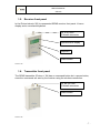
1.5. Receiver front panel
In the Picture below(n°03) is represented SEMS receiver front panel. It has a
display and a command keyboard.
RF in 50 Ohm
N female connector
Alphanumeric display
Keyboard
Power button
Picture n°03
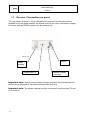
1.6. Transmitter front panel
The SEMS transmitter (Picture n° 04) has no command button but a power button,
since the commands are sent by the receiver using the wireless connection.
RF out 50 Ohm
N female connector
Power button
Picture n°04
-7-