1
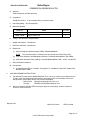
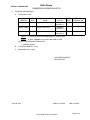
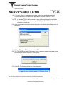
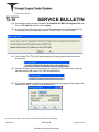
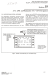
TECHNICAL BULLETIN
407-14-111
3 July 2014
MODEL AFFECTED:
407
SUBJECT:
ENGINE
FADEC
INTRODUCTION OF
HELICOPTERS AFFECTED:
Serial numbers 53000 through 53900, 53911
through 54175, and 54300 through 54570.
SOFTWARE
V5.400,
[Serial numbers 54176 through 54299 and 54571
and subsequent will have the intent of this bulletin
accomplished prior to delivery.]
COMPLIANCE:
At customer’s option.
DESCRIPTION:
This Technical Bulletin provides the instructions to introduce the software
Version 5.400 to the engine FADEC system of the Model 407 (standard and 407GX).
Bell Helicopter Textron has been coordinating closely with Rolls-Royce Corporation
(RRC) to implement this software upgrade to resolve the FADEC faults associated
with the introduction of the overspeed adapter per the ASB 407-14-102, as well as
some other known Reversionary Governor faults that have been identified in the RRC
Commercial Service Letter (CSL) 6125. The software upgrade will also be a
terminating action to Part III of the ASB 407-14-102 that requires a 50-hour recurring
functional check of the overspeed protection system and will be introduced as a
revision to the subject ASB. Compliance with Part I of the ASB 407-14-102 (RollsRoyce Corporation ALERT CEB A-73-6059) must be accomplished prior to or
concurrently with this Technical Bulletin. This installs the engine adapter P/N M25010684 to the helicopter FADEC harness. Applicability of this bulletin to any spare part
shall be determined prior to its installation on an affected helicopter.
APPROVAL:
The engineering design aspects of this bulletin are Transport Canada Civil Aviation
(TCCA) approved.
TB 407-14-111
Page 1 of 6
Export Classification C, ECCN EAR99
Approved for public release.
CONTACT INFO:
For any questions regarding this bulletin, please contact:
Bell Helicopter Product Support Engineering - Light Helicopters
Tel: 450-437-2862 / 1-800-363-8023 / [email protected]
MANPOWER:
Approximately 2.0 man-hours are required to complete this bulletin. This estimate is
based on hands-on time, and may vary with personnel and facilities available.
WARRANTY:
There is no warranty credit applicable for parts or labor associated with this bulletin.
MATERIAL:
Required Material:
The following material is required for the accomplishment of this bulletin and may be
obtained through your Bell Helicopter Textron Supply Center.
Part Number
Nomenclature
407-075-011-115
407-075-206-133
113417-1
MS51861-1C
DECAL 5.400 DRM
DECAL 5.400 DRM
ECU IDENTIFICATION PLATE
SCREW, SELF-TAPPING
Qty
Notes
1
1
1
4
(Note 1 and 3)
(Note 2 and 4)
(Note 5)
(Note 5)
Notes:
1. Decal required for the standard 407 (S/N 53000 through 54299).
2. Decal required for the 407GX (S/N 54300 through 54570).
3. The decal may be locally manufactured using lettering of white color No. 17875 on
a black background color No. 17038 per FED STD595. Characters to be 12 points
Helvetica Regular. Text for the decal is detailed in Figure 1.
4. The decal may be locally manufactured using lettering of white color No. 17875 on
a black background color No. 17038 per FED STD595. Characters to be 10 points
Spartan Black. Text for the decal is detailed in Figure 1.
5. The required material will be supplied by Triumph Engine Control Systems (TECS)
as part of the software upgrade campaign.
TB 407-14-111
Page 2 of 6
Export Classification C, ECCN EAR99
Approved for public release.
Consumable Material:
The following material is required to accomplish this bulletin, but may not require
ordering, depending on the operator’s consumable material stock levels. This material
may be obtained through your Bell Helicopter Textron Supply Center.
Part Number
Nomenclature
2110-00010-00
NAPTHA-MB1041 - TT-N95,TYII 1GAL
COMPOUND-SEALER 3950 SCOTCHCAL
2010-06640-00
Qty
Reference *
As required
C-305
As required
C-349
* C-XXX numbers refer to the consumables list in BHT-ALL-SPM Standard Practices Manual
SPECIAL TOOLS:
Refer to the required Tooling section per the Triumph Engine Control Systems (TECS)
Service Bulletin 73-10. This will be supplied as part of the software upgrade program.
WEIGHT AND BALANCE:
Not affected.
ELECTRICAL LOAD DATA:
Not affected.
REFERENCES:
BHT-407-IPB Illustrated Parts Breakdown, Chapters 11, 76, 95, and 96
BHT-407-MM Maintenance Manual, Chapters 11, 71, 76, 95, and 96
Bell Helicopter Alert Service Bulletin (ASB) 407-14-102
BHT-407-FM-1 Flight Manual, Temporary Revision 14
BHT-407-FM-2 Flight Manual, Temporary Revision 4
Rolls-Royce Corporation ALERT Commercial Engine Bulletin (CEB) A-73-6059
Rolls-Royce Corporation Commercial Engine Bulletin (CEB) 73-6060
Rolls-Royce Corporation Commercial Service Letter (CSL) 6125
Triumph Engine Control Systems (TECS) Service Bulletin (SB) 73-10
PUBLICATIONS AFFECTED:
BHT-407-IPB Illustrated Parts Breakdown, Chapters 11, 76, 95, and 96
BHT-407-MM Maintenance Manual, Chapters 11, 71, 76, 95, and 96
BHT-407-FM-1 Flight Manual
BHT-407-FM-2 Flight Manual
BHT-407-MD-1 Manufacturer’s Data
BHT-407-MD-2 Manufacturer’s Data
TB 407-14-111
Page 3 of 6
Export Classification C, ECCN EAR99
Approved for public release.
ACCOMPLISHMENT INSTRUCTIONS:
-NOTECompliance with Part I of the ASB 407-14-102 (Rolls-Royce
Corporation CEB A-73-6059) shall be accomplished prior to
or concurrently with this Technical Bulletin. This installs the
engine adapter P/N M250-10684 to the helicopter FADEC
harness.
1. Refer to the Rolls-Royce Corporation (RRC) Commercial Engine Bulletin (CEB)
73-6060 to verify applicability of this bulletin to the ECU part number installed on
the helicopter.
a. If the ECU is affected, do step 2.
b. If the ECU is not affected, do step 8.
2. Prepare the helicopter for maintenance.
3. Perform the Accomplishment Instructions of the Rolls-Royce CEB 73-6060 and the
Triumph Engine Control Systems (TECS) Service Bulletin 73-10.
4. With a plastic scraper, remove and discard the existing FADEC software version
decal located on the instrument panel. Wipe the surface clean with a clean damp
cloth, moistened with aliphatic naphtha (C-305) (Figure 1).
5. Install applicable decal on the instrument panel in the location identified.
6. Seal the edges of the decal with edge sealer (C-349).
7. Insert temporary revisions into the appropriate Rotorcraft Flight Manual (RFM).
a. Insert Temporary Revision 14 into the BHT-407-FM-1, Flight Manual (407).
b. Insert Temporary Revision 4 into the BHT-407-FM-2, Flight Manual (407GX).
8. Make an entry in the helicopter logbook and historical service records indicating
compliance with this Technical Bulletin.
TB 407-14-111
Page 4 of 6
Export Classification C, ECCN EAR99
Approved for public release.
Figure 1 – Markings Installation (Sheet 1 of 2)
TB 407-14-111
Page 5 of 6
Export Classification C, ECCN EAR99
Approved for public release.
Figure 1 – Markings Installation (Sheet 2 of 2)
TB 407-14-111
Page 6 of 6
Export Classification C, ECCN EAR99
Approved for public release.
COMMERCIAL ENGINE
BULLETIN
EXPORT CONTROLLED
ENGINE, FUEL AND CONTROL -- NEW ECU SOFTWARE
1.
PLANNING INFORMATION
A.
Effectivity
(1) Engines
All Rolls-Royce M250--C47B series engines with the following ECUs installed:
C47B
23080490
23088484
23088856
(2) Spares -- Not affected
B.
Reason
The new software addresses the “power--up faults” and “overspeed shutdown test disable” which
were introduced with the adapter installed via CEB--A--73--6059.
C.
Description
Installation of the false overspeed trip (FOST) adapter (M250--10684) generates power--up faults. It
also makes the “overspeed test function” inoperable. With this software update, the engine
operation will be restored to normal operation prior to the adapter install. The new software will also
provide confirmation that the adapter is installed. It will generate a fault if the adapter is NOT
installed.
The following software changes are incorporated into this software version:
(1) Change the overspeed protection logic to accommodate the FOST adapter, (M250--10684).
The software will now check for the presence of the adapter and declare faults (OSCnfigFlt and
OSFlt) if adapter is not detected. The overspeed shutdown test will now function with the
adapter installed.
(2) Improvement in the NG Fault detection including eliminating nuisance faults on shutdown.
(3) Added fault detection on starter circuit to check for a stuck “on” condition.
(4) Improvement in Incident recorder detection logic.
(5) Improvement in the igniter circuit fault detection logic.
(6) Elimination of nuisance Watch Dog Timer faults in the reversionary governor.
(7) Improvement in the primary to reversionary governor hand--off logic.
For C47M operators, new software is planned to make the above changes. This bulletin will be
revised at that time to include the C47M part numbers and compliance information.
May 29, 2014
M250--C47 Series
E2014 Rolls--Royce Corporation
CEB--73--6060
Page 1 of 3
Rolls-Royce
EXPORT CONTROLLED
COMMERCIAL ENGINE BULLETIN
D.
Approval
Technical aspects are FAA approved.
E.
Compliance
Compliance Code 7. To be complied with per customer option.
F.
Interchangeability -- See Prerequisites
G. Material Availability
NAME
NEW P/N
QTY/ENG
M250--10695
Engine Control Unit
1
M250--10696
Engine Control Unit
1
H.
Tooling -- See attached Triumph bulletin.
I.
Weight and Balance -- Not affected
J.
Electrical Load Data -- Not affected
K.
References
(1) Advance Engineering Memorandum (AEM), CW500020268050.
NOTE:
The document above is referenced for the internal use of Rolls-Royce only.
(2) CSP 21001 Operation and Maintenance Manual, Turboshaft Model M250--C47B (OMM).
(3) CSP 23001 Illustrated Parts Catalog, Turboshaft Models M250--C40B, --C47B, --C47M (IPC).
L.
Other Publications Affected
M. Prerequisites
(1) Compliance with CEB--A--73--6059 -- Paragraph 2.A., Installation of the FOST adapter Part
Number M250--10684.
2.
ACCOMPLISHMENT INSTRUCTIONS
A.
See attached Triumph Service Bulletin EMC35R 73.10. Once you receive your software kit from
Triumph, verify part number and serial number information on the new data plate. If there are
discrepancies, contact Rolls--Royce and Triumph immediately.
Rolls--Royce:
[email protected]
Triumph:
[email protected]
B.
Record compliance with this CEB in the engine log book, white pages, and the component
accessory card for the ECU.
May 29, 2014
M250--C47 Series
CEB--73--6060
Page 2 of 3
E2014 Rolls--Royce Corporation
Rolls-Royce
EXPORT CONTROLLED
COMMERCIAL ENGINE BULLETIN
3.
MATERIAL INFORMATION
A.
Configuration Chart
NEW P/N
QTY/
ENG
QTY/
ENG
INSTRUCTIONS/
DISPOSITION
M250--10695
1
Engine Control Unit
23080490
(See Note 1)
1
1
M250--10695
1
Engine Control Unit
23088484
(See Note 1)
1
1
M250--10696
1
Engine Control Unit
23088856
(See Note 2)
1
1
NAME
OLD P/N
NOTE:
(1) ECUs 23080490 and 23088484 are pre CEB 73--6052.
NOTE:
(2) ECU 23088856 has complied with CEB 73--6052.
INSTRUCTIONS/DISPOSITION NOTES
1. Software updated.
B.
Consumable Materials -- None
C.
Expendable Parts -- None
CUSTOMER SUPPORT
ROLLS-ROYCE
May 29, 2014
M250--C47 Series
E2014 Rolls--Royce Corporation
CEB--73--6060
Page 3 of 3
SERVICE BULLETIN
EMC-35R ECU
73-10
Triumph Engine Control Systems Model EMC-35R
Electronic Control Unit Assembly
Software Upgrade for Rolls-Royce 250-C47B Engine
1. Planning Information
A. Effectivity
Applicable to the Triumph Engine Control Systems (Triumph) model EMC-35R Electronic
Control Unit Assembly (ECU) part numbers 115220-1A5-20, 115220-1A5-23 and 1152202A5-23 (Rolls-Royce Part Numbers 23080490, 23088484, and 23088856, respectively) as
components of the Rolls-Royce 250-C47B engine.
B. Reason
To upgrade part number 115220-1A5-20, 115220-1A5-23, or 115220-2A5-23 (Rolls-Royce
Part Number 23080490, 23088484, or 23088856, respectively) to part number 115220-1A524 or 115220-2A5-24 (Rolls-Royce part numbers M250-10695 and M250-10696,
respectively) by changing the embedded software for the Primary governor from version
257-5356 (-20) or 257-5358 (-23) to 257-5400, and the embedded software for the
Reversionary governor from version 681-9026 (-20) or 681-9029 (-23) to 681-9100. The
primary objective of the new software is to make the power-up and shutdown overspeed
tests compatible with the overspeed adapter (Rolls-Royce P/N M250-10684) that is installed
between the engine harness and firewall connector (refer to Rolls-Royce CEB-A-73-6059).
C. Description
This service bulletin provides instructions for changing the embedded software for the
Primary governor from version 257-5356 or 257-5358 to 257-5400, and the embedded
software for the Reversionary governor from version 681-9026 or 681-9029 to 681-9100
using the on-line loader functionality of the ECU. The task is accomplished using an IBM
compatible personal computer (PC) with Windows XP, 7, or 8 operating system and the
following Triumph supplied hardware/software:
(1) Programming interface cable
(2) Programming interface box
(3) On-Line Loader interface software
(4) Maintenance Terminal software
(5) Bell 407 Maintenance Terminal data files
(6) Embedded software files for versions 257-5400 and 681-9100
The on-line loader (OLL) function which is run on the personal computer, will completely
erase the existing embedded Primary governor and Reversionary software and upload the
new software version to replace it. The on-line loader function automatically verifies
successful erasure of the existing software and automatically verifies the integrity of the new
These commodities, technology or software are controlled by the U.S. Export Administration Regulations (EAR). Diversion contrary
to U.S. law is prohibited. ECCN: 9E991
May 29/14
M250-C47B
Rolls-Royce Proprietary Document
Page 1 of 27
EMC-35R ECU
SERVICE BULLETIN
73-10
software version by a supplemental identification (a.k.a CRC) check. The operator is
required to verify and document that the software version and supplemental identifier
number are correct.The operator is also required to verify and document that the engine
history data displayed after software upload are identical to those displayed before upload.
It is not possible to end up with a ‘dead’ ECU due to a unsuccessful upload, regardless of the
cause. The boot loader code is resident in the ECU flash memory and cannot be corrupted
by a terminated upload. Once power is cycled with the programming switch in the active
state, the boot loader restarts execution and is again ready to receive programming
instructions and data from the PC.
Configuration control is maintained by removing the identification plate prior to the software
change and by changing the unit part number onto a new identification plate and on
applicable documents after the ECU is programmed with the new software.
D. Compliance
At customer discretion but only in conjunction with or after the installation of the overspeed
adapter (Rolls-Royce P/N M250-10684) per Rolls-Royce CEB-A-73-6059.
E. Approval
Technical aspects are FAA approved.
F. Manpower
All work is to be performed by FAA authorized personnel only. Approximately 1.0 man hour
is required to accomplish this upgrade.
G. Material - Price and Availability
Item
Nomenclature
1
ECU Identification Plate
2
Screw, Self-Tapping
Part Number
Quantity
113417-1*
1
MS51861-1C*
4
* Contact Triumph account manager for availability
This document is subject to the controls and restrictions as stated on the title page.
May 29/14
M250-C47B
Rolls-Royce Proprietary Document
Page 2 of 27
SERVICE BULLETIN
EMC-35R ECU
73-10
H. Tooling
*
Item
Part Number
1
118737-1*
2
CD118743-1
3
Nomenclature
Quantity
EMC-35R ECU Programming Kit for C47B,
consisting of items 2 through 9, below.
1
CD: Bell 407 250-C47B FOSSA
1
T-11527-4
Programming Interface Cable
1
4
T-11527-5
Programming Interface Box
1
5
N/A
RS232 Extension Cable, 6 foot (or 2M); D-sub
9-pin male to 9-pin female
1
6
USA-19HS
Keyspan USB-to-Serial Converter
1
7
N/A
Universal 24 VDC Power Supply Module
(100 - 240VAC 50/60 Hz input, 2.1 amps
minimum output)
1
8
N/A
AC Power Cord (Nema 5-15P/IEC60320-C13;
18 AWG min., 3 conductor, 6 foot minimum
length, 240 VAC min.)
1
9
N/A
International AC Plug Adapter
1
10
CD118794-1*
CD: Maintenance Terminal 2013
1
11
CD118758-1*
CD: Bell 407 250-C47B Maintenance
Terminal Data Files
1
12
113972-3*
Maintenance Terminal Interface Cable
1
13
C-1912 Rev - *
Maintenance Terminal User’s Manual
1
14
N/A
Personal Computer (PC) with Windows
XP/7/8 Operating System, CDROM Drive,
and 9-Pin RS232 Serial Port or USB Port
1
15
N/A
Small Phillips Head Screwdriver
1
Contact Triumph Account Manager for availability
This document is subject to the controls and restrictions as stated on the title page.
May 29/14
M250-C47B
Rolls-Royce Proprietary Document
Page 3 of 27
EMC-35R ECU
73-10
SERVICE BULLETIN
I. Weight and Balance
None.
J. Electrical Load Data
Not Changed.
K. Software Accomplishment Summary
The software accomplishment summary for software versions 257-5400 and 681-9100 is
Triumph document C-1105-24, latest revision.
L. References
None.
M. Other Publications Affected
Not Applicable.
This document is subject to the controls and restrictions as stated on the title page.
May 29/14
M250-C47B
Rolls-Royce Proprietary Document
Page 4 of 27
SERVICE BULLETIN
EMC-35R ECU
73-10
2. Accomplishment Instructions
Precautions
(1) To ensure software integrity, the Triumph-supplied CDs are write protected. If there is
any damage to the CDs or any question of CD integrity, consult Triumph for replacement
CDs before attempting accomplishment instructions.
(2) The operator should verify that the PC is free of virus infection using a commercially
available anti-virus program with recently updated virus detection files. The protocol and
automated checks of the on-line loader function prevent the possibility of infecting
software in the ECU. However it is possible for virus infection to cause operating
problems with the PC which could inhibit completion of the accomplishment instructions.
(3) Powering the ECU without normal airframe connections will cause numerous faults to be
logged in RAM (volatile) memory due to loss of external signals. Observed faults should
be disregarded except as specifically addressed in these instructions.
(4) Steps 2.A through 2.E can be completed in advance while away from the aircraft. Steps
2.F through 2.L will require access to the aircraft and are required to be completed in
consecutive order, as written.
(5) It is recommended that programming of the ECU be completed with a PC that is running
off AC power rather than battery power, to ensure that the PC does not shut down in the
middle of the reprogramming process.
(6) It is recommended that if a PC that has been historically used to run the Maintenance
Terminal software is available, it also be used to support reprogramming of the ECU
since the serial communications port has already been set up and demonstrated to be
functional.
(7) If a PC with Maintenance Terminal version 2.00 or 2.01 is not available, complete the
registration of the CD for Maintenance Terminal 2013 (version 2.3) in order to receive an
installation password. A registration form and instructions can be found in the
Maintenance Terminal User’s Manual.
(8) If programming of the Primary governor or Reversionary governor is unsuccessful for
any reason, it is recommended that the PC be re-booted, the ECU be de-powered, and
the programming process be restarted from the first step of the applicable paragraph;
2.H for the Primary governor, 2.I for the Reversionary governor.
(9) Ensure that a replacement ECU identification plate is available before proceeding past
step 2.F. of this bulletin.
A. Install Maintenance Terminal Software
NOTES: It is not necessary to re-install the Maintenance Terminal software from the CD
each time this service bulletin is accomplished. It is also not necessary to install the
Maintenance Terminal 2013 software (version 2.3) if an earlier version (v2.0, v2.01)
has been previously installed onto the PC. Refer to Maintenance Terminal User’s
Manual if any difficulties with the installation are encountered. The user must have
administrator rights on the PC in order to install the software.
This document is subject to the controls and restrictions as stated on the title page.
May 29/14
M250-C47B
Rolls-Royce Proprietary Document
Page 5 of 27
EMC-35R ECU
SERVICE BULLETIN
73-10
(1) Insert the Maintenance Terminal 2013 CD (CD118794-1) into CDROM drive.
(2) From the Windows toolbar, click on Start > Run.
(3) Click on Browse and navigate to the CDROM drive containing the CD.
(4) Select Setup.exe and click on Open.
(5) Click on OK.
(6) A window titled Setup for Maintenance Terminal Version 2.3 will be displayed. As
directed, close all other programs that are running. Click on Next.
(7) A window identifying the default destination folder for Maintenance Terminal will be
displayed. Click on Next..
(8) A window identifying the default destination folder for the Maintenance Terminal icon will
be displayed. Click on Next.
(9) A window indicating that the installation is completed will be displayed. Click on Finish.
(10) Remove the Maintenance Terminal Program CD from the CDROM drive.
B. Install Maintenance Terminal Data Files for the Bell 407
NOTE:
It is not necessary to re-install the Maintenance Terminal data files from the CD for
the Bell 407 software each time this service bulletin is accomplished. The user
must have administrator rights on the PC in order to install the software.
(1) Insert the Bell 407 250-C47B Maintenance Terminal Data Files CD (CD118758-1) into
the CDROM drive.
(2) From the Windows toolbar, click on Start > Run.
(3) Click on Browse and navigate to the CDROM drive containing the CD.
(4) Select Setup.exe and click on Open.
(5) Click on OK.
(6) A setup wizard for version 4.1 of the C47B Maintenance Terminal data files will open. As
directed, close all other programs that are running. Click on Next.
(7) A window identifying the default destination folder for the data files will be displayed.
Click on Next..
(8) A window indicating that the data files are ready to install will be displayed. Click on
Install.
(9) A window indicating that the installation is completed will be displayed. Click on Finish.
(10) Remove the Maintenance Terminal Data file CD for the Bell 407 from the CDROM drive.
This document is subject to the controls and restrictions as stated on the title page.
May 29/14
M250-C47B
Rolls-Royce Proprietary Document
Page 6 of 27
SERVICE BULLETIN
EMC-35R ECU
73-10
C. Install On-Line Loader Software and Embedded ECU Software Files
NOTE:
It is not necessary to re-install the On-Line Loader software and embedded ECU
software files each time this service bulletin is accomplished.
(1) Create a C:\temp folder on the PC if it does not already exist.
(2) Insert Bell 407 250-C47B FOSSA CD (CD118743-1) into the CDROM drive.
(3) Browse to the CDROM drive.
(4) Browse to IMAGE_CD118743-1_REV(5) Right click on EMC35_TTOLLI folder and click Copy
(6) Browse to C:, right click on the temp folder, and click on Paste.
(7) Browse again to IMAGE_CD118743-1_REV- on the CDROM drive.
(8) Right click on Bell 407 EMC-35 Program Files folder and click Copy.
(9) Browse again to C:, right click on the temp folder, and click on Paste.
(10) Remove the Bell 407 250-C47B FOSSA CD from the CDROM drive.
D. Install USB-to-Serial Adapter and Software
NOTE:
The USB-to-Serial adapter driver files only need to be installed if the PC does not
have a 9-pin serial port or if another USB-to-Serial converter has not been installed
previously. Also, it is not necessary to re-install the driver files each time this
service bulletin is accomplished.
(1) Insert the Bell 407 250-C47B FOSSA CD (CD118743-1) into the CDROM drive.
(2) Browse to the CDROM drive.
(3) Browse to folder IMAGE_CD118743-1_REV- \ Keyspan USB Files.
(4) Depending upon the PC operating system, double-click on the appropriate setup file as
defined below:
(a) USA-19HS Windows (98, ME)_v3.4.exe
(b) USA-19HS Windows (2000, XP, 2003 Server, Vista)_v3.75.exe
(c) USA-19S Windows 7v4.exe (also use for Windows 8)
(5) Follow setup screens to complete installation of necessary files for the USB-to-serial
adapter (Keyspan manuals are on the CD if needed).
(6) Plug the USB-to-Serial adapter into a USB port on the PC. The driver file will be installed
automatically.
(7) Remove the Bell 407 250-C47B FOSSA CD from the CDROM drive.
This document is subject to the controls and restrictions as stated on the title page.
May 29/14
M250-C47B
Rolls-Royce Proprietary Document
Page 7 of 27
EMC-35R ECU
SERVICE BULLETIN
73-10
E. Determine Serial COM Port Assignment
NOTE:
The serial COM port assignment only has to be determined if the PC did not have
Maintenance Terminal software installed prior to initiating this service bulletin.
(1) From the Windows toolbar menu click on Start > Control Panel > System > Device
Manager > Ports (COM & LPT).
(2) If PC has a 9-pin serial port connector, note the COM port assignment (typically COM1).
(3) If USB-to-serial adapter is being used, note the COM port assignment for the adapter.
NOTE:
The Maintenance Terminal software only supports COM port assignment up to and
including COM9. If the COM port assignment is higher than COM9, refer to the
Keyspan manual on the Bell 407 250-C47B FOSSA CD (CD118743-1) for
instructions on how to change the COM port assignment.
F. Record Software Version, Serial Number and Engine History Data Prior to Re-programming
ECU
NOTE:
If it is not possible to provide AC power at the aircraft location, the ECU may be
removed from the aircraft for reprogramming.
(1) If ECU is to be programmed on aircraft, complete steps (2) through (5) below.
Otherwise, begin at step (6) below.
(2) Remove dust cap from FADEC ECU communications port on left side of pedestal.
(3) Connect one end of the Maintenance Terminal interface cable to FADEC ECU
communications port and the other end to the 9-pin COM port on PC (or USB-to-serial
adapter).
(4) Apply airframe power to the ECU.
(5) Go to step (17) below.
(6) Plug the circular plug on the programming interface cable into the J2 connector on ECU.
(7) Plug the 15-pin ‘D’ connector on the programming interface cable labeled as ‘P104’ into
the ‘J104’ connector on the programming interface box.
(8) Set the programming switch on the programming interface box to center ‘OFF/ECUIC’
position.
(9) Set the power switch position on the programming interface box to ‘OFF”.
(10) Connect AC power cord to power supply module.
(11) Connect power supply module output plug to receptacle labeled as ‘J101’ on the
programming interface box.
(12) If PC does not have 9-pin serial port, install USB-to-serial converter to one of the USB
ports (if not already installed).
This document is subject to the controls and restrictions as stated on the title page.
May 29/14
M250-C47B
Rolls-Royce Proprietary Document
Page 8 of 27
SERVICE BULLETIN
EMC-35R ECU
73-10
(13) Connect one end of the 9-pin RS232 cable to the 9-pin serial port on the PC (or USB-toserial converter).
(14) Connect the other end of the 9-pin RS232 cable to the receptable labeled as ‘J102’ on
the interface box.
(15) Plug the AC power cord into a 110 - 240VAC 50/60 Hz outlet.
(16) Set the power switch on the programming box to ‘PWR ON’.
(17) From the Windows toolbar, click on Start > Programs> Maintenance Terminal. If
running Maintenance Terminal version 2.00 or 2.01 click on Maintenance Terminal. If
running Maintenance Terminal 2013 (version 2.3), right click on Maintenance Terminal
and select Run as administrator. This is only necessary for the first time the
Maintenance Terminal version 2.3 is used.
(18) If prompted for a password, enter the existing password (or password supplied during
registration of Maintenance Terminal version 2.3) and click OK.
(19) From the MTerm main menu, click on File > Select COM port.
(20) Note the active COM port. The active COM port number will be required as part of the
ECU programming steps. Click OK.
(21) Initiate MTerm communications with the ECU by clicking on the ‘connect’ icon at top left
of MTerm window.
(22) Verify the following information from the Component Serial Numbers screen. Record
compliance on record data sheet, Appendix A, paragraph 1.A.:
(a) ECU Software Version 257-5356 and Supplemental ID 6058, OR
(b) ECU Software Version 257-5358 and Supplemental ID 211A
(23) Record the following serial number information from the screen on the record data
sheet, Appendix A, paragraph 1.C:
(a) ECU S/N:
(b) Engine S/N:
(c) Compressor S/N:
(d) HMU S/N:
(e) Aircraft ID:
(f) Turbine S/N:
(g) Eng Gearbox S/N:
(24) Click on OK.
(25) On MTerm main menu, click on Engine History > View.
This document is subject to the controls and restrictions as stated on the title page.
May 29/14
M250-C47B
Rolls-Royce Proprietary Document
Page 9 of 27
EMC-35R ECU
73-10
SERVICE BULLETIN
(26) Record the displayed values for the following engine history data on the record data
sheet , Appendix A, paragraph 1.D:
(a) ECURnTm
(b) NpRLmPk
(c) NpRLmTm
(d) NumStrt
(e) OSCyc
(f) SgCtr
(g) EngRunCtr
(h) NpLmPk
(i) NpLmTm
(j) OSCtr
(k) NpLmEvts
(does not apply to ECU software version 257-5356)
(l) NpRLmEvts
(does not apply to ECU software version 257-5356)
(m) NpMLmEvts
(does not apply to ECU software version 257-5356)
(n) NpExcInd
(does not apply to ECU software version 257-5356)
(27) Disconnect the MTerm from the ECU by clicking on the ‘disconnect’ icon at the top left of
the window.
(28) Exit the MTerm by clicking on File > Exit.
(29) If previous steps were performed with ECU on aircraft, complete steps (30) through (32).
Otherwise, set the power switch position on the programming interface box to OFF’.
(30) Remove aircraft power from ECU.
(31) Disconnect Maintenance Terminal cable from the FADEC ECU communications port and
from the 9-pin COM port on PC (or USB-to-serial adapter).
(32) Replace dust cap on the FADEC ECU communications port.
G. Connect Programming Equipment
(1) Using a small Phillips screwdriver, remove the four screws securing the identification
plate to the ECU housing. Retain screws and identification plate for transfer of
information onto new identification plate in accordance with step 2.L.
(2) Complete steps (3) through (15) only if programming equipment was not previously
connected in paragraph 2.F.
(3) Ensure aircraft power is removed from ECU.
This document is subject to the controls and restrictions as stated on the title page.
May 29/14
M250-C47B
Rolls-Royce Proprietary Document
Page 10 of 27
SERVICE BULLETIN
EMC-35R ECU
73-10
(4) Remove cable clamp closest to ECU J2 connector.
(5) Disconnect airframe harness from ECU J2 connector.
(6) Plug the circular plug on the programming interface cable into the J2 connector on ECU.
(7) Plug the 15-pin ‘D’ connector on the programming interface cable labeled as ‘P104’ into
the ‘J104’ connector on the programming interface box.
(8) Set the programming switch on the programming interface box to center ‘OFF/ECUIC’
position.
(9) Set the power switch position on the programming interface box to ‘OFF”.
(10) Connect AC power cord to power supply module.
(11) Connect power supply module output plug to receptacle labeled as ‘J101’ on the
programming interface box.
(12) If PC does not have a 9-pin serial port, install USB-to-serial converter to one of the USB
ports (if not already installed).
(13) Connect one end of the 9-pin RS232 cable to the 9-pin serial port on the PC (or USB-toserial converter).
(14) Connect the other end of the 9-pin RS232 cable to the receptacle labeled as ‘J102’ on
the interface box.
(15) Plug the AC power cord into a 110 - 240VAC 50/60 Hz outlet.
H. Re-program the Primary Governor
NOTE:
It is recommended that this paragraph (H) and subsequently paragraph (I) be
performed without interruption. Plan for a minimum of 20 minutes to complete both
paragraphs.
(1) Connect equipment as described in paragraph 2.G above.
(2) Set the switch on the programming box to ‘PRIMARY PROGRAM’ (full down position)
(3) Set the power switch on the programming box to ‘PWR ON’.
(4) Browse to C:\temp\EMC35_TTOLLI and click on the Start shortcut.
(5) The following dialogue box will appear:
This document is subject to the controls and restrictions as stated on the title page.
May 29/14
M250-C47B
Rolls-Royce Proprietary Document
Page 11 of 27
EMC-35R ECU
73-10
SERVICE BULLETIN
(6) Click on Yes. The following dialogue box will appear and prompt for the COM port
number.
(7) Enter the serial communications port number which was determined in step 2.E or
2.F(20). Click on OK.
(8) If the port is already in use, the following message will be displayed:
This document is subject to the controls and restrictions as stated on the title page.
May 29/14
M250-C47B
Rolls-Royce Proprietary Document
Page 12 of 27
SERVICE BULLETIN
EMC-35R ECU
73-10
(9) If this error occurs, it must determined which applications are already using the
communications port and close those applications and then restart the TTOLLI
application and try to connect again.
NOTE:
An aborted TTOLLI application can in some cases leave the serial port locked.
Consult the TTOLLI users manual (C-1913-001) on CD118743-1for directions on
unlocking the serial port.
(10) Upon a successful connection with the serial port, the following menu dialogue box is
displayed:
(11) Click on Program Primary and click on OK.
(12) The TTOLLI will then display the current Primary governor software version as shown
below (may be C-00257-5356 or C-00257-5358):
(13) Click OK. The following status box will be displayed:
This document is subject to the controls and restrictions as stated on the title page.
May 29/14
M250-C47B
Rolls-Royce Proprietary Document
Page 13 of 27
EMC-35R ECU
73-10
SERVICE BULLETIN
(14) An explorer window will open. Browse to C:\temp\Bell 407 EMC-35 Program Files and
click on 257-5400.oll and then click on Open.
(15) A message box will be displayed to confirm the software version to be loaded into the
Primary governor (existing version may be C-00257-5356 or C-00257-5358):
(16) Click on Yes. The TTOLLI will begin erasing the Primary governor flash memory as
shown below:
(17) Once the Primary governor flash memory is erased, the TTOLLI will begin to program
the flash memory with version 257-5400 as shown below:
(18) A file transfer status box will then be displayed showing the progress of the software file
transfer from the PC to the ECU as shown below:
This document is subject to the controls and restrictions as stated on the title page.
May 29/14
M250-C47B
Rolls-Royce Proprietary Document
Page 14 of 27
SERVICE BULLETIN
EMC-35R ECU
73-10
WARNING: DO NOT CLICK ON CLOSE, PAUSE, OR HELP DURING THE PROGRAMMING
PROCESS OR THE UPLOAD WILL TERMINATE.
NOTE:
It will take approximately 6 minutes to program the Primary governor. It is
recommended to move the mouse every 2 - 3 minutes to prevent the PC from
going to sleep during the programming process, which could terminate the upload
and lock up the serial port.
(19) When programming the Primary governor is complete, the transfer status box will close
and a message box will be displayed as shown below:
(20) Click on OK. The TTOLLI will then read back the uploaded version of software from the
ECU and display it as shown below. Record confirmation of the Primary governor
software version the on record data sheet, Appendix A, paragraph 1.E.(1).
(21) Click on OK. The TTOLLI will then read the supplemental identifier from the ECU and
display it as shown below. Record confirmation of the Primary governor supplemental
identifier on the record data sheet, Appendix A, paragraph 1.E.(2).
(22) Click on OK. A status box will be displayed indicating that programming of the Primary
governor is complete
(23) Set the power switch on the programming box to ‘OFF’.
This document is subject to the controls and restrictions as stated on the title page.
May 29/14
M250-C47B
Rolls-Royce Proprietary Document
Page 15 of 27
EMC-35R ECU
73-10
SERVICE BULLETIN
I. Re-Program the Reversionary Governor
(1) Move the 9-pin RS232 cable from the ‘J102’ receptacle on the programming interface
box to the ‘J103’ receptacle.
(2) Set the switch on the programming box to ‘REVER PROGRAM’ (full up position).
(3) Set the power switch on the programming box to ‘PWR ON’.
(4) At the TTOLLI main menu dialogue box, click on Program Reversionary and
click OK.
(5) The TTOLLI will then display the current Reversionary governor software version as
shown below (may be C-00681-9026 or C-00681-9029)
(6) Click OK. The following status box will be displayed.
(7) An explorer window will open. Browse to C:\temp\Bell 407 EMC-35 Program Files and
click on 681-9100.oll and then click on Open.
This document is subject to the controls and restrictions as stated on the title page.
May 29/14
M250-C47B
Rolls-Royce Proprietary Document
Page 16 of 27
SERVICE BULLETIN
EMC-35R ECU
73-10
(8) A message box will be displayed to confirm the software version to be loaded into the
Reversionary governor (existing version may be C-00681-9026 or C-00681-9029).
(9) Click on Yes. The TTOLLI will upload a flash kernel to Reversionary governor RAM
memory as shown below:
WARNING: DO NOT CLICK ON CLOSE, PAUSE, OR HELP DURING THE PROGRAMMING
PROCESS OR THE UPLOAD WILL TERMINATE.
(10) It will take approximately 1 minute to upload the flash kernel to the Reversionary
governor. Once the flash kernel is uploaded, it will start execution and erase the flash
memory.
This document is subject to the controls and restrictions as stated on the title page.
May 29/14
M250-C47B
Rolls-Royce Proprietary Document
Page 17 of 27
EMC-35R ECU
73-10
SERVICE BULLETIN
(11) After the Reversionary governor flash memory is erased, the TTOLLI will begin to
program the flash memory with version 681-9100.
(12) A file transfer status box will then be displayed showing the progress of the software file
transfer from the PC to the Reversionary governor flash memory as shown below:
WARNING: DO NOT CLICK ON CLOSE, PAUSE, OR HELP DURING THE PROGRAMMING
PROCESS OR THE UPLOAD WILL TERMINATE.
NOTE:
It will take approximately 5 minutes to program the Reversionary governor. It is
recommended to move the mouse every 2 - 3 minutes to prevent the PC from
going to sleep during the programming process, which could terminate the upload
and lock up the serial port.
(13) When programming the Reversionary governor is complete, the transfer status box will
close and a message box will be displayed as shown below:
This document is subject to the controls and restrictions as stated on the title page.
May 29/14
M250-C47B
Rolls-Royce Proprietary Document
Page 18 of 27
SERVICE BULLETIN
EMC-35R ECU
73-10
(14) Click on OK. The TTOLLI will then read back the uploaded version of software from the
ECU and display it as shown below. Record confirmation of the Reversionary governor
software version on the record data sheet, Appendix A, paragraph 1.F.(1).
(15) Click on OK. The TTOLLI will then read the supplemental identifier from the ECU and
display it as shown below. Record confirmation of the supplemental identifier on the
record data sheet, Appendix A, paragraph 1.F.(2).
(16) Click on OK. A status box will be displayed indicating that programming of the
Reversionary governor is complete.
This document is subject to the controls and restrictions as stated on the title page.
May 29/14
M250-C47B
Rolls-Royce Proprietary Document
Page 19 of 27
EMC-35R ECU
73-10
SERVICE BULLETIN
(17) At the TTOLLI main menu dialogue box, click on Cancel to exit the program.
(18) Set the power switch on the programming box to OFF.
J. Verify Software Version, Serial Numbers and Engine History Data After
Reprogramming ECU
(1) Move the 9-pin RS232 cable from the ‘J103’ receptacle on the programming interface
box back to the ‘J102’ receptacle.
(2) Set the programing switch to the center ‘OFF/ECUIC’ position.
(3) Set the power switch position on the programming interface box to ‘PWR ON’
(4) From the Windows toolbar, click on Start > Programs> Maintenance Terminal >
Maintenance Terminal.
(5) If prompted for a password, enter the supplied password and click OK.
(6) Initiate Maintenance Terminal communications with the ECU by clicking on the ‘connect’
icon at top left of MTerm window.
(7) Verify the following information from the Component Serial Numbers screen. Record
compliance on record data sheet, Appendix A, paragraph 1.B.
(a) ECU Software Version 257-5400 and Supplemental ID E844.
(8) Verify that the component serial numbers are identical to those recorded in step 2.F(23)
prior to reprogramming the Primary governor software. If identical, place a check mark in
the brackets to the right of the associated component serial number on the record data
sheet, Appendix A, paragraph 1.C.
(9) Click on OK
(10) On toolbar at top of the MTerm window, click on Engine History > View. A Parameter
Edit window will be displayed.
This document is subject to the controls and restrictions as stated on the title page.
May 29/14
M250-C47B
Rolls-Royce Proprietary Document
Page 20 of 27
SERVICE BULLETIN
EMC-35R ECU
73-10
(11) Verify that the values for the displayed engine history data are identical to those
recorded in step 2.F(26) prior to reprogramming the Primary governor software. If
identical, place a check mark in the brackets to the right of the associated parameter on
the record data sheet, Appendix A, paragraph 1.D.
(12) Complete steps 13 through 19 below for original ECU configuration 115220-1A520 only.
(13) Record values for the Np strike data values on the record data sheet, Appendix A,
paragraphs 1.D.(11) through (14).
(14) Verify the following Np strike data values in the engine history data:
(a) NpLmEvts = 0
(b) NpRLmEvts = 0
(c) NpMLmEvts = 0
(d) NpExcInd = FALSE
(15) If the engine log card contains Np strike data (or if the Np exceedance data recorded by
the ECU meets criteria for recording strike data), the Np strike data in the ECU memory
should be edited to reflect actual strike status. Refer to the 250-C47B engine O & M
manual for determining strike status from Np exceedance information. Update the
recorded value on the record data sheet, Appendix A, paragraph 1.D.(11).
(16) To edit the Np strike data in the ECU memory, from the MTerm main menu, click on
Engine History > Edit. A Parameter Edit window will be displayed.
(17) Click on NpLmEvts and Click on Edit.
(18) Edit the value for the parameter and click on OK. The data will be written to the ECU.
(19) When prompted, cycle the power switch on the interface box to ‘OFF’ for a couple of
seconds, then back to ‘PWR ON’. Click OK.
(20) Disconnect the MTerm from the ECU by clicking on the ‘disconnect’ icon at the top left of
the window.
(21) Exit the MTerm by clicking on File > Exit on toolbar at top of Mterm window.
(22) Set the power switch position on the programming interface box to ‘OFF’
K. Disconnect Equipment and Re-connect ECU to Aircraft
(1) Ensure the power switch on the interface box to the ‘OFF’ position
(2) Disconnect the circular plug on the interface cable from the J2 connector on ECU.
(3) Connect airframe harness to J2 connector on ECU.
(4) Re-install cable clamp closest to ECU J2 connnector.
This document is subject to the controls and restrictions as stated on the title page.
May 29/14
M250-C47B
Rolls-Royce Proprietary Document
Page 21 of 27
EMC-35R ECU
SERVICE BULLETIN
73-10
L. Re-identify the ECU
(1) Replace the identification plate previously removed in step 2.G(1) with a new
identification plate (5, Figure 1) using four new screws (10, Figure 1) showing the
appropriate Triumph part number (see Table below). Record compliance after new
identification plate is installed on record data sheet, Appendix A, paragraph G.(1).
Existing Part Number
New Part Number
Triumph
Rolls-Royce
Triumph
Rolls-Royce
115220-1A5-20
23080490
115220-1A5-24
M250-10695
115220-1A5-23
23088484
115220-1A5-24
M250-10695
115220-2A5-23
23088856
115220-2A5-24
M250-10696
Verify that the ECU serial number on the identification plate matches the ECU serial
number recorded on the record data sheet, Appendix A, paragraph C.(1). Record
compliance on the record data sheet, Appendix A, paragraph G.(2).
All other identification plate information remains unchanged. If necessary, other service
bulletin information shall be transferred from the old identification plate to the new
identification plate prior to installation using a marking method such as hand scribing,
vibro-etching or metal stamping.
M. Record Compliance with Service Bulletin
After the new identification plate has been installed, record compliance information as
specified on Service Bulletin Compliance Data Sheet (Appendix B). Remit to Triumph Engine
Control Systems via mail, fax, or email as specified on the form.
This document is subject to the controls and restrictions as stated on the title page.
May 29/14
M250-C47B
Rolls-Royce Proprietary Document
Page 22 of 27
EMC-35R ECU
SERVICE BULLETIN
73-10
Figure 1. ECU Identification Plate Replacement
Item Number
Quantity
Nomenclature
Part Number
5
1
Plate, Identification
113417-1
10
4
Screw, Self Tapping
MS51861-1C
This document is subject to the controls and restrictions as stated on the title page.
May 29/14
M250-C47B
Rolls-Royce Proprietary Document
Page 23 of 27
EMC-35R ECU
SERVICE BULLETIN
73-10
3. Material Information
The basis for the following is per the Electronic Control Unit assembly.
Nomenclature
Old Part Number
Instructions /
Disposition
New Part Number
Quantity
113417-1
1
Plate, Identification, ECU
MS51861-1C
4
Screw, Self-tapping
115220-1A5-24
(M250-10695)
1
Electronic Control Unit
115220-1A5-20
(23080490)
Re-identify
115220-1A5-24
(M250-10695)
1
Electronic Control Unit
115220-1A5-23
(23088484)
Re-identify
115220-2A5-24
(M250-10696)
1
Electronic Control Unit
115220-2A5-23
(23088856)
Re-identify
113417-1
MS51861-1C
Destroy and
Scrap
Scrap
This document is subject to the controls and restrictions as stated on the title page.
May 29/14
M250-C47B
Rolls-Royce Proprietary Document
Page 24 of 27
EMC-35R ECU
SERVICE BULLETIN
73-10
APPENDIX A
SERVICE BULLETIN RECORD SHEET
1. Record and Verify Data Extracted from ECU
A. As instructed in step 2.F(22), place check mark in brackets after verifying the following
information from the prior to reprogramming the ECU:
(1) ECU Software Version: 257-5356 with supp ID 6058 [
] OR
(2) ECU Software Version: 257-5358 with supp ID 211A [
]
B. As instructed in step 2.J(7), place check mark in brackets after verifying the following
information from the after reprogramming the ECU:
(1) ECU Software Version: 257-5400 with supp ID E844 [
]
C. As instructed in step 2.F(23), record the following S/N information below prior to
reprogramming the Primary governor. Place check mark in brackets after verifying S/N data
is identical after reprogramming the ECU as instructed in step 2.J(8).
(1) ECU S/N:
_______________
[
]
(2) Engine S/N:
_______________
[
]
(3) Compressor S/N:
_______________
[
]
(4) HMU S/N:
_______________
[
]
(5) Aircraft ID:
_______________
[
]
(6) Turbine S/N:
_______________
[
]
(7) Eng Gearbox S/N:
_______________
[
]
D. As instructed in step 2.F(26) record the following engine history data below prior to
reprogramming the Primary governor. Place check mark in brackets after verifying engine
history data is identical after reprogramming the ECU as instructed in step 2.J(11). For
original ECU configuration 115220-1A5-20,record values for items k through n (Items 11 - 14
below) after reprogramming the ECU as instructed in step 2.J(13).
(1) ECURnTm
_______________
Hours
[
]
(2) NpRLmPk
_______________
%Np
[
]
(3) NpRLmTm
_______________
Seconds
[
]
(4) NumStrt
_______________
Starts
[
]
(5) OSCyc
_______________
Boolean
[
]
(6) SgCtr
_______________
Surges
[
]
(7) EngRunCtr
_______________
Seconds
[
]
This document is subject to the controls and restrictions as stated on the title page.
May 29/14
M250-C47B
Rolls-Royce Proprietary Document
Page 25 of 27
EMC-35R ECU
SERVICE BULLETIN
73-10
(8) NpLmPk
_______________
%Np
[
]
(9) NpLmTm
_______________
Seconds
[
]
(10) OSCtr
_______________
Events
[
]
(11) NpLmEvts
_______________
Counts
[
]
(12) NpRLmEvts
_______________
Counts
[
]
(13) NpMLmEvts
_______________
Counts
[
]
(14) NpExcInd
_______________
Boolean
[
]
E. As instructed in steps 2.H(20) and 2.H(21), place a check mark in the brackets after verifying
the following information from the after reprogramming of the Primary governor.
(1) ECU Software Version:
257-5400
[
]
(2) ECU Supplemental ID:
E844
[
]
F. As instructed in step 2.I(14) and 2.I(15), place a check mark in the brackets after verifying
the following information from the after reprogramming of the Reversionary Governor.
(1) ECU Software Version:
681-9100
[
]
(2) ECU Supplemental ID:
11C2
[
]
G. As instructed in step 2.L(1), place a check mark in the brackets after verifying that the
identification plate has been changed to reflect the new ECU part number and that the ECU
serial number on the identification plate matches the serial number recorded in step C.(1)
above.
(1) Identification Plate changed
[
]
(2) ECU serial number on identification plate
matches serial number recorded in C.(1)
[
]
This document is subject to the controls and restrictions as stated on the title page.
May 29/14
M250-C47B
Rolls-Royce Proprietary Document
Page 26 of 27
SERVICE BULLETIN
EMC-35R ECU
73-10
APPENDIX B
SERVICE BULLETIN COMPLIANCE DATA SHEET
ECU Serial Number:____________________
ECU Identification Plate Before EMC-35A ECU Service Bulletin 73-10
Triumph P/N _______________
Rolls-Royce P/ N _______________
ECU Identification Plate After EMC-35A ECU Service Bulletin 73-10
Triumph P/N _______________
Rolls-Royce P/ N_______________
The above ECU is in compliance with EMC-35R ECU Service Bulletin 73-10, Latest
Revision.
Facility/Company:
______________________________
Address:
______________________________
______________________________
______________________________
Date of Compliance:
______________________________
Contact name:
______________________________
Contact phone:
______________________________
Engine serial number:
______________________________
Aircraft serial number:
______________________________
Submit the completed Service Bulletin Compliance Data Sheet (this page) to Triumph
Engine Control Systems via one of the following methods:
Regular mail
Mail to:
Triumph Engine Control Systems
Attn: Brian Beal
1 Charter Oak Boulevard
P.O. Box 330651
West Hartford, CT 06133-0651
Fax
Fax to (860) 231-2706
E-mail
Scan and e-mail to [email protected]
This document is subject to the controls and restrictions as stated on the title page.
May 29/14
M250-C47B
Rolls-Royce Proprietary Document
Page 27 of 27