1
ÎÎ
GE Fanuc Automation
Programmable Control Products
C Programmer’s Toolkit
for Series 90 PCMs
t
User’s Manual
GFK-0771A
August 1996
GFL–002
Warnings, Cautions, and Notes
as Used in this Publication
Warning
Warning notices are used in this publication to emphasize that
hazardous voltages, currents, temperatures, or other conditions that
could cause personal injury exist in this equipment or may be
associated with its use.
In situations where inattention could cause either personal injury or
damage to equipment, a Warning notice is used.
Caution
Caution notices are used where equipment might be damaged if care is
not taken.
Note
Notes merely call attention to information that is especially significant to
understanding and operating the equipment.
This document is based on information available at the time of its publication. While
efforts have been made to be accurate, the information contained herein does not
purport to cover all details or variations in hardware or software, nor to provide for
every possible contingency in connection with installation, operation, or maintenance.
Features may be described herein which are not present in all hardware and software
systems. GE Fanuc Automation assumes no obligation of notice to holders of this
document with respect to changes subsequently made.
GE Fanuc Automation makes no representation or warranty, expressed, implied, or
statutory with respect to, and assumes no responsibility for the accuracy, completeness,
sufficiency, or usefulness of the information contained herein. No warranties of
merchantability or fitness for purpose shall apply.
The following are trademarks of GE Fanuc Automation North America, Inc.
Alarm Master
CIMPLICITY
CIMPLICITY PowerTRAC
CIMPLICITY 90–ADS
CIMSTAR
Field Control
GEnet
Genius
Genius PowerTRAC
Helpmate
Logicmaster
Modelmaster
PowerMotion
ProLoop
PROMACRO
Series Five
Series 90
Copyright 1993–1996 GE Fanuc Automation North America, Inc.
All Rights Reserved
Series One
Series Six
Series Three
VuMaster
Workmaster
Preface
This manual contains essential information about the design and construction of C
language application programs for the GE Fanuc Series 90 Programmable Coprocessor
Module (PCM). It is written for experienced C programmers who are also familiar with
the operation of Series 90 PLCs. Readers new to the C programming language or to
Series 90 PLCs should familiarize themselves thoroughly with these topics before
attempting to use the material in this manual. The list of publications at the end of this
section contains helpful references.
t
General information on PCM hardware, its installation and operation, and connecting a
personal computer (PC) to a PCM can be found in the Series 90 Programmable Coprocessor
Module and Support Software User’s Manual, GFK-0255, revision D or later.
Content of this Manual
Chapter 1. Introduction: Chapter 1 describes the PCM C toolkit and lists some types of
applications which have been successfully implemented in C on the PCM.
Chapter 2. Installation: Chapter 2 lists the items you will need to develop PCM
applications in C, explains how to install the PCM C toolkit, and describes how
Microsoftr C version 6.00 must be installed.
Chapter 3. Creating and Running PCM C Programs: Chapter 3 describes the creation
and installation of a simple C program for the PCM.
Chapter 4. Using PCM Resources: Chapter 4 describes how to use the hardware
resources of the PCM, the facilities of its VTOS operating system, and services provided
by the PLC CPU from C applications.
Chapter 5. PCM Libraries and Header Files: Chapter 5 lists all the services provides by
the PCM C libraries and the C header files which describe them to the C compiler.
Chapter 6. PCM Real Time Programming: Chapter 6 describes some important issues
in real time communication and control applications, and how to address them in PCM
applications.
Chapter 7. Multitasking: Chapter 7 describes how to use multiple PCM tasks to design
a real time application, and how to run two or more independent applications in the
same PCM.
Chapter 8. Memory Models: Chapter 8 describes the memory models which the PCM
supports.
Chapter 9. Example Programs: Chapter 9 describes the sample programs provided with
the PCM C toolkit.
Chapter 10. Applications In ROM: Chapter 10 describes how to install PCM
applications in PCM Read–Only Memory (ROM).
Chapter 11. Utilities: Chapter 11 describes the utility programs provided with the PCM
C toolkit.
GFK-0771A
iii
Preface
Chapter 12. GE Fanuc Support Services: Chapter 12 describes the consultation services
provided by GE Fanuc to each purchaser of the PCM C toolkit.
Appendix A. Microsoft Runtime Library Support: Appendix A lists all the functions
provided in the Microsoft C 6.00 runtime libraries, and indicates which ones are
applicable to the PCM.
Appendix B. PCM Commands: Appendix B is a complete reference to the PCM
command interpreter.
Appendix C. Batch Files: Appendix C describes how to control PCM operation with
batch files.
Appendix D. PCM C Directories and Files: Appendix D lists all the directories and files
created on your hard disk during installation of the PCM C toolkit.
Related Publications
For more information, refer to these publications:
t
Series 90 -70 ProgrammableController Installation Manual (GFK-0262): This manual
describes the hardware used in a Series 90-70 PLC system, and explains system setup
and operation.
t
Logicmaster 90-70 Programming Software User’s Manual (GFK-0263): This manual
describes operation of Logicmaster 90-70 software for configuring, programming,
monitoring, and controlling a Series 90-70 PLC and/or remote I/O drop.
t
Series 90 -70 ProgrammableController Reference Manual (GFK-0265): This manual
describes program structure and instructions for the Series 90-70 PLC.
t
Series 90 -30 ProgrammableController Installation Manual (GFK-0356): This manual
describes the hardware used in a Series 90-30 PLC system, and explains system setup
and operation.
t
Logicmaster 90 Series 90-30 and 90-20 Programming Software User’s Manual
(GFK-0466): This manual describes operation of Logicmaster 90-30 software for
configuring, programming, monitoring, and controlling a Series 90-30 PLC.
t
Series 90 -30/90-20 ProgrammableControllersReference Manual (GFK-0467): This
manual describes program structure and instructions for the Series 90-30 PLC.
PCM C Function Library Reference Manual (GFK-0772): This manual provides a
complete reference to all the library functions provided in the PCM runtime libraries for
the PCM C toolkit.
The C Primer. Hancock, Les, and Morris Krieger. New York: McGraw-Hill Book Co.,
Inc., 1982.
C: A Reference Manual. Harbison, Samuel P., and Greg L. Steele. Englewood Cliffs, New
Jersey: Prentice-Hall, Inc., Third Edition, 1988.
The C Programming Language. Kernighan, Brian W., and Dennis M. Ritchie. Englewood
Cliffs, New Jersey: Prentice-Hall, Inc., Third Edition, 1988.
iv
C Programmer’s Toolkit for Series 90 PCMs User’s Manual – August 1996
GFK-0771A
Preface
Programming in C. Kochan, Stephen. Hasbrouck Heights, New Jersey: Hayden Book
Co., Inc., 1983.
Learning to Program in C. Plum, Thomas. Cardiff, New Jersey: Plum Hall, Inc., 1983.
We Welcome Your Comments and Suggestions
At GE Fanuc Automation, we strive to produce quality technical documentation. After
you have used this manual, please take a few moments to complete and return the
Reader ’s Comment Card located on the next page.
Henry Konat
Senior Technical Writer
GFK-0771A
Preface
v
Contents
Chapter 2
Chapter 3
Chapter 4
GFK-0771A
Introduction . . . . . . . . . . . . . . . . . . . . . . . . . . . . . . . . . . . . . . . . . . . . . . .
1-1
Why Develop PCM Applications In C? . . . . . . . . . . . . . . . . . . . . . . . . . . . .
1-1
AppropriateApplications . . . . . . . . . . . . . . . . . . . . . . . . . . . . . . . . . . . . . . .
1-1
Limitations . . . . . . . . . . . . . . . . . . . . . . . . . . . . . . . . . . . . . . . . . . . . . . . . . . .
1-2
Expertise Required . . . . . . . . . . . . . . . . . . . . . . . . . . . . . . . . . . . . . . . . . . . . .
1-2
Getting Started . . . . . . . . . . . . . . . . . . . . . . . . . . . . . . . . . . . . . . . . . . . . . . . .
1-2
Installation . . . . . . . . . . . . . . . . . . . . . . . . . . . . . . . . . . . . . . . . . . . . . . . .
2-1
What You Will Need . . . . . . . . . . . . . . . . . . . . . . . . . . . . . . . . . . . . . . . . . . .
2-1
Microsoft C Installation Requirements . . . . . . . . . . . . . . . . . . . . . . . . . . . .
2-2
Installing the PCM C Toolkit . . . . . . . . . . . . . . . . . . . . . . . . . . . . . . . . . . . . .
2-3
Adding \PCMC to Your MS-DOS Path . . . . . . . . . . . . . . . . . . . . . . . . . . . .
2-4
Adding\PCMC\LIBtoYour LIB Environment Variable . . . . . . . . . . . . . .
2-4
Adding\PCMC\INCLUDE to Your INCLUDE Environment Variable . .
2-5
Switching Between PCM and MS-DOS Application Development . . . .
2-6
Creating and Running PCM C Programs . . . . . . . . . . . . . . . . . . . . . .
3-1
Creating C Source Files . . . . . . . . . . . . . . . . . . . . . . . . . . . . . . . . . . . . . . . . .
3-1
Compiling Sources . . . . . . . . . . . . . . . . . . . . . . . . . . . . . . . . . . . . . . . . . . . . .
3-2
Linking Objects . . . . . . . . . . . . . . . . . . . . . . . . . . . . . . . . . . . . . . . . . . . . . . . .
3-3
Specifying the Stack Size . . . . . . . . . . . . . . . . . . . . . . . . . . . . . . . . . . . . . . . .
3-3
Loading Executable Files . . . . . . . . . . . . . . . . . . . . . . . . . . . . . . . . . . . . . . . .
3-5
Running a PCM Task . . . . . . . . . . . . . . . . . . . . . . . . . . . . . . . . . . . . . . . . . . .
3-7
Debugging a PCM Task . . . . . . . . . . . . . . . . . . . . . . . . . . . . . . . . . . . . . . . . .
3-7
Using Makefiles . . . . . . . . . . . . . . . . . . . . . . . . . . . . . . . . . . . . . . . . . . . . . . .
3-8
C Programmer’s Toolkit for Series 90 PCMs User’s Manual – August 1996
vii
Contents
Chapter 5
viii
Using PCM Resources . . . . . . . . . . . . . . . . . . . . . . . . . . . . . . . . . . . . . .
4-1
PCM Hardware Resources . . . . . . . . . . . . . . . . . . . . . . . . . . . . . . . . . . . . . .
4-1
The VTOS Operating System . . . . . . . . . . . . . . . . . . . . . . . . . . . . . . . . . . . .
4-1
The VTOS File System . . . . . . . . . . . . . . . . . . . . . . . . . . . . . . . . . . . . . . . . . .
4-2
The PCM Command Interpreter . . . . . . . . . . . . . . . . . . . . . . . . . . . . . . . . .
4-3
Accessing PLC Data From PCM Programs . . . . . . . . . . . . . . . . . . . . . . . . .
4-3
VTOS CPU: Device Services . . . . . . . . . . . . . . . . . . . . . . . . . . . . . . . . . . . . .
4-3
PLC API Services . . . . . . . . . . . . . . . . . . . . . . . . . . . . . . . . . . . . . . . . . . . . . .
4-3
Communications Request (COMMREQ) Messages From PLC Programs
4-4
Programming COMMREQ Function Blocks . . . . . . . . . . . . . . . . . . . . . . . .
4-5
The COMMREQ Command and Data Blocks . . . . . . . . . . . . . . . . . . . . . .
4-6
Receiving COMMREQ Messages In a PCM Program . . . . . . . . . . . . . . . .
4-8
Responding to COMMREQs . . . . . . . . . . . . . . . . . . . . . . . . . . . . . . . . . . . .
4-10
Regulating the Timing of COMMREQ Messages . . . . . . . . . . . . . . . . . . .
4-11
Using Series 90-70 VME Function Blocks . . . . . . . . . . . . . . . . . . . . . . . . . .
4-12
VME Function Blocks for Communicating with the PCM . . . . . . . . . . . .
4-12
Some Rules for VME Bus Operations in Series 90-70 PLCs . . . . . . . . . . .
4-12
General VME Information for the PCM . . . . . . . . . . . . . . . . . . . . . . . . . . .
4-13
PCM Dual Port RAM Available for Applications . . . . . . . . . . . . . . . . . . . .
4-14
VME Read Function . . . . . . . . . . . . . . . . . . . . . . . . . . . . . . . . . . . . . . . . . . . .
4-15
VME Write Function . . . . . . . . . . . . . . . . . . . . . . . . . . . . . . . . . . . . . . . . . . . .
4-17
VMERead/Modify/Write Function . . . . . . . . . . . . . . . . . . . . . . . . . . . . . . .
4-19
VME Test and Set Function . . . . . . . . . . . . . . . . . . . . . . . . . . . . . . . . . . . . . .
4-21
C Program Access to PCM Dual Port RAM . . . . . . . . . . . . . . . . . . . . . . . . .
4-22
C Programmer’s Toolkit for Series 90 PCMs User’s Manual – August 1996
GFK-0255J
Contents
Chapter 6
Chapter 7
GFK-0771A
PCM Libraries and Header Files . . . . . . . . . . . . . . . . . . . . . . . . . . . . .
5-1
PCM Libraries . . . . . . . . . . . . . . . . . . . . . . . . . . . . . . . . . . . . . . . . . . . . . . . . .
5-1
VTOS Interface . . . . . . . . . . . . . . . . . . . . . . . . . . . . . . . . . . . . . . . . . . . . . . . .
5-1
VTOS Services By Category . . . . . . . . . . . . . . . . . . . . . . . . . . . . . . . . . . . . .
5-1
Event Flag Functions . . . . . . . . . . . . . . . . . . . . . . . . . . . . . . . . . . . . . . . . . . .
5-2
Asynchronous Trap Functions . . . . . . . . . . . . . . . . . . . . . . . . . . . . . . . . . . .
5-3
Semaphore Functions . . . . . . . . . . . . . . . . . . . . . . . . . . . . . . . . . . . . . . . . . .
5-3
Time-of-Day Clock Functions . . . . . . . . . . . . . . . . . . . . . . . . . . . . . . . . . . . .
5-4
Timer Functions . . . . . . . . . . . . . . . . . . . . . . . . . . . . . . . . . . . . . . . . . . . . . . .
5-5
Communication Timer Functions . . . . . . . . . . . . . . . . . . . . . . . . . . . . . . . . .
5-5
Memory Management Functions . . . . . . . . . . . . . . . . . . . . . . . . . . . . . . . . .
5-6
Memory Module Functions . . . . . . . . . . . . . . . . . . . . . . . . . . . . . . . . . . . . .
5-7
Device I/O Functions . . . . . . . . . . . . . . . . . . . . . . . . . . . . . . . . . . . . . . . . . . .
5-7
Device Driver Support Functions . . . . . . . . . . . . . . . . . . . . . . . . . . . . . . . . .
5-9
Miscellaneous Functions . . . . . . . . . . . . . . . . . . . . . . . . . . . . . . . . . . . . . . . .
5-10
VTOS Macros . . . . . . . . . . . . . . . . . . . . . . . . . . . . . . . . . . . . . . . . . . . . . . . . .
5-10
VTOS Types . . . . . . . . . . . . . . . . . . . . . . . . . . . . . . . . . . . . . . . . . . . . . . . . . . .
5-11
VTOS Global Data . . . . . . . . . . . . . . . . . . . . . . . . . . . . . . . . . . . . . . . . . . . . .
5-13
The PLC API Interface . . . . . . . . . . . . . . . . . . . . . . . . . . . . . . . . . . . . . . . . . .
5-13
PLC API Services By Category . . . . . . . . . . . . . . . . . . . . . . . . . . . . . . . . . . .
5-13
PLC API Types . . . . . . . . . . . . . . . . . . . . . . . . . . . . . . . . . . . . . . . . . . . . . . . .
5-17
PLC API Global Data . . . . . . . . . . . . . . . . . . . . . . . . . . . . . . . . . . . . . . . . . . .
5-18
Using Standard C Libraries . . . . . . . . . . . . . . . . . . . . . . . . . . . . . . . . . . . . . .
5-19
Restrictions . . . . . . . . . . . . . . . . . . . . . . . . . . . . . . . . . . . . . . . . . . . . . . . . . . .
5-19
Using printf In Small and Medium Models . . . . . . . . . . . . . . . . . . . . . . . .
5-20
Header Files . . . . . . . . . . . . . . . . . . . . . . . . . . . . . . . . . . . . . . . . . . . . . . . . . .
5-20
PCM Real-Time Programming . . . . . . . . . . . . . . . . . . . . . . . . . . . . . . .
6-1
Asynchronous Events . . . . . . . . . . . . . . . . . . . . . . . . . . . . . . . . . . . . . . . . . .
6-1
VTOS Asynchronous I/O Scenario . . . . . . . . . . . . . . . . . . . . . . . . . . . . . . . .
6-1
VTOS Asynchronous Timer Scenario . . . . . . . . . . . . . . . . . . . . . . . . . . . . .
6-2
Local Event Flag Notification . . . . . . . . . . . . . . . . . . . . . . . . . . . . . . . . . . . .
6-3
AST Notification and Execution Threads . . . . . . . . . . . . . . . . . . . . . . . . . .
6-3
Strategies For Predictable Real-Time Performance . . . . . . . . . . . . . . . . . .
6-4
Using WAIT Mode Event Processing . . . . . . . . . . . . . . . . . . . . . . . . . . . . . .
6-4
Using EVENT_NOTIFY Mode Event Processing . . . . . . . . . . . . . . . . . . . .
6-6
Using AST_NOTIFY Mode Event Processing . . . . . . . . . . . . . . . . . . . . . . .
6-9
Differences between ASTs and MS-DOS ISRs . . . . . . . . . . . . . . . . . . . . . .
6-14
Other Considerations When Using Asynchronous Traps . . . . . . . . . . . . .
6-15
C Programmer’s Toolkit for Series 90 PCMs User’s Manual – August 1996
ix
Contents
Chapter 8
Chapter 9
Chapter 10
Chapter 11
Chapter 12
x
Multitasking . . . . . . . . . . . . . . . . . . . . . . . . . . . . . . . . . . . . . . . . . . . . . .
7-1
Why Use Multitasking? . . . . . . . . . . . . . . . . . . . . . . . . . . . . . . . . . . . . . . . . .
Task Priorities . . . . . . . . . . . . . . . . . . . . . . . . . . . . . . . . . . . . . . . . . . . . . . . . .
VTOS Tasks . . . . . . . . . . . . . . . . . . . . . . . . . . . . . . . . . . . . . . . . . . . . . . . . . . .
Task Startup . . . . . . . . . . . . . . . . . . . . . . . . . . . . . . . . . . . . . . . . . . . . . . . . . . .
Task Scheduling . . . . . . . . . . . . . . . . . . . . . . . . . . . . . . . . . . . . . . . . . . . . . . .
Priority-Based Tasks . . . . . . . . . . . . . . . . . . . . . . . . . . . . . . . . . . . . . . . . . . . .
Time-Slice Tasks . . . . . . . . . . . . . . . . . . . . . . . . . . . . . . . . . . . . . . . . . . . . . . .
Interaction of Priority and Time-Slice Tasks . . . . . . . . . . . . . . . . . . . . . . . .
Task Contention for PCM Serial Ports . . . . . . . . . . . . . . . . . . . . . . . . . . . . .
Communication Between Tasks . . . . . . . . . . . . . . . . . . . . . . . . . . . . . . . . . .
Event Flags . . . . . . . . . . . . . . . . . . . . . . . . . . . . . . . . . . . . . . . . . . . . . . . . . . .
Shared Memory Modules . . . . . . . . . . . . . . . . . . . . . . . . . . . . . . . . . . . . . . .
Creating Memory Modules From Applications . . . . . . . . . . . . . . . . . . . . .
Asynchronous Traps . . . . . . . . . . . . . . . . . . . . . . . . . . . . . . . . . . . . . . . . . . . .
Semaphores . . . . . . . . . . . . . . . . . . . . . . . . . . . . . . . . . . . . . . . . . . . . . . . . . . .
Debugging Multiple Tasks . . . . . . . . . . . . . . . . . . . . . . . . . . . . . . . . . . . . . . .
Dumping PCM Task State Information . . . . . . . . . . . . . . . . . . . . . . . . . . . .
Using In-Circuit Emulators . . . . . . . . . . . . . . . . . . . . . . . . . . . . . . . . . . . . . .
7-1
7-1
7-2
7-2
7-2
7-3
7-3
7-4
7-6
7-6
7-7
7-8
7-12
7-14
7-17
7-21
7-21
7-21
Memory Models . . . . . . . . . . . . . . . . . . . . . . . . . . . . . . . . . . . . . . . . . . .
8-1
Models Supported By the PCM . . . . . . . . . . . . . . . . . . . . . . . . . . . . . . . . . .
Small and Medium Model Differences Between VTOS and MS-DOS . .
Advantages and Restrictions . . . . . . . . . . . . . . . . . . . . . . . . . . . . . . . . . . . .
Making the Most of Small and Medium Models . . . . . . . . . . . . . . . . . . . .
8-1
8-2
8-4
8-4
Example Programs . . . . . . . . . . . . . . . . . . . . . . . . . . . . . . . . . . . . . . . . .
9-1
PLC Hardware Requirements . . . . . . . . . . . . . . . . . . . . . . . . . . . . . . . . . . .
Logicmaster 90 Compatibility . . . . . . . . . . . . . . . . . . . . . . . . . . . . . . . . . . . .
Logicmaster 90-30 Configuration . . . . . . . . . . . . . . . . . . . . . . . . . . . . . . . . .
PCM Rack and Slot Location . . . . . . . . . . . . . . . . . . . . . . . . . . . . . . . . . . . .
Building The PCM Executable Files . . . . . . . . . . . . . . . . . . . . . . . . . . . . . . .
The PCM Tasks . . . . . . . . . . . . . . . . . . . . . . . . . . . . . . . . . . . . . . . . . . . . . . . .
PLC Ladder Program . . . . . . . . . . . . . . . . . . . . . . . . . . . . . . . . . . . . . . . . . . .
9-1
9-1
9-2
9-2
9-2
9-3
9-7
Applications in ROM . . . . . . . . . . . . . . . . . . . . . . . . . . . . . . . . . . . . . . .
10-1
Restrictions . . . . . . . . . . . . . . . . . . . . . . . . . . . . . . . . . . . . . . . . . . . . . . . . . . .
Building ROM Applications . . . . . . . . . . . . . . . . . . . . . . . . . . . . . . . . . . . . .
10-1
10-2
Utilities . . . . . . . . . . . . . . . . . . . . . . . . . . . . . . . . . . . . . . . . . . . . . . . . . . .
11-1
STKMOD Program . . . . . . . . . . . . . . . . . . . . . . . . . . . . . . . . . . . . . . . . . . . . .
PCMDUMP Program . . . . . . . . . . . . . . . . . . . . . . . . . . . . . . . . . . . . . . . . . . .
Task Register and Stack Data . . . . . . . . . . . . . . . . . . . . . . . . . . . . . . . . . . . .
Using Microsoft Map Files . . . . . . . . . . . . . . . . . . . . . . . . . . . . . . . . . . . . . . .
BLD_PROM Program . . . . . . . . . . . . . . . . . . . . . . . . . . . . . . . . . . . . . . . . . .
Customizing the PROM Copyright String . . . . . . . . . . . . . . . . . . . . . . . . .
11-1
11-3
11-8
11-10
11-11
11-13
C Programmer’s Toolkit for Series 90 PCMs User’s Manual – August 1996
GFK-0255J
Contents
Chapter 13
GE Fanuc Support Services and Consultation . . . . . . . . . . . . . . . . .
11-1
Appendix A
Microsoft Runtime Library Support . . . . . . . . . . . . . . . . . . . . . . . . . .
A-1
Appendix B
PCM Commands . . . . . . . . . . . . . . . . . . . . . . . . . . . . . . . . . . . . . . . . . . .
B-1
Accessing the Command Interpreter . . . . . . . . . . . . . . . . . . . . . . . . . . . . . .
B-1
Interactive Mode . . . . . . . . . . . . . . . . . . . . . . . . . . . . . . . . . . . . . . . . . . . . . .
B-2
Notation Conventions . . . . . . . . . . . . . . . . . . . . . . . . . . . . . . . . . . . . . . . . . .
B-3
Commands . . . . . . . . . . . . . . . . . . . . . . . . . . . . . . . . . . . . . . . . . . . . . . . . . . .
B-3
@ (Execute a Batch File) . . . . . . . . . . . . . . . . . . . . . . . . . . . . . . . . . . . . . . . .
B-4
Appendix C
Appendix D
GFK-0771A
B (Configure LEDs) . . . . . . . . . . . . . . . . . . . . . . . . . . . . . . . . . . . . . . . . . . . .
B-5
C (Clear the PCM) . . . . . . . . . . . . . . . . . . . . . . . . . . . . . . . . . . . . . . . . . . . . .
B-6
D (file Directory) . . . . . . . . . . . . . . . . . . . . . . . . . . . . . . . . . . . . . . . . . . . . . . .
B-6
F (Show Free Memory) . . . . . . . . . . . . . . . . . . . . . . . . . . . . . . . . . . . . . . . . .
B-7
G (Get Hardware ID) . . . . . . . . . . . . . . . . . . . . . . . . . . . . . . . . . . . . . . . . . . .
B-7
H (Get PCM Firmware Revision Number) . . . . . . . . . . . . . . . . . . . . . . . . .
B-7
I (Initialize Device) . . . . . . . . . . . . . . . . . . . . . . . . . . . . . . . . . . . . . . . . . . . . .
B-8
J (Format EEROM Device) . . . . . . . . . . . . . . . . . . . . . . . . . . . . . . . . . . . . . .
B-11
K (Kill a Task) . . . . . . . . . . . . . . . . . . . . . . . . . . . . . . . . . . . . . . . . . . . . . . . . . .
B-11
L (Load) . . . . . . . . . . . . . . . . . . . . . . . . . . . . . . . . . . . . . . . . . . . . . . . . . . . . . .
B-12
M (Create a Memory Module) . . . . . . . . . . . . . . . . . . . . . . . . . . . . . . . . . . .
B-13
O (Get LED Configuration) . . . . . . . . . . . . . . . . . . . . . . . . . . . . . . . . . . . . . .
B-13
P (Request Status Data) . . . . . . . . . . . . . . . . . . . . . . . . . . . . . . . . . . . . . . . . .
B-14
Q (Set Protection Level) . . . . . . . . . . . . . . . . . . . . . . . . . . . . . . . . . . . . . . . .
B-15
R (Run) . . . . . . . . . . . . . . . . . . . . . . . . . . . . . . . . . . . . . . . . . . . . . . . . . . . . . . .
B-15
S (Save) . . . . . . . . . . . . . . . . . . . . . . . . . . . . . . . . . . . . . . . . . . . . . . . . . . . . . .
B-17
U (Reconfigure the PCM) . . . . . . . . . . . . . . . . . . . . . . . . . . . . . . . . . . . . . . .
B-18
V (Verify a File) . . . . . . . . . . . . . . . . . . . . . . . . . . . . . . . . . . . . . . . . . . . . . . . .
B-18
W (Wait) . . . . . . . . . . . . . . . . . . . . . . . . . . . . . . . . . . . . . . . . . . . . . . . . . . . . . .
B-18
X (eXterminate file) . . . . . . . . . . . . . . . . . . . . . . . . . . . . . . . . . . . . . . . . . . . .
B-19
Y (Set Upper Memory Limit) . . . . . . . . . . . . . . . . . . . . . . . . . . . . . . . . . . . .
B-19
Batch Files . . . . . . . . . . . . . . . . . . . . . . . . . . . . . . . . . . . . . . . . . . . . . . . .
C-1
Overview . . . . . . . . . . . . . . . . . . . . . . . . . . . . . . . . . . . . . . . . . . . . . . . . . . . . .
C-1
Creating Batch Files . . . . . . . . . . . . . . . . . . . . . . . . . . . . . . . . . . . . . . . . . . . .
C-1
Running Batch Files . . . . . . . . . . . . . . . . . . . . . . . . . . . . . . . . . . . . . . . . . . . .
C-2
PCMEXEC.BAT Files . . . . . . . . . . . . . . . . . . . . . . . . . . . . . . . . . . . . . . . . . . .
C-2
HARDEXEC.BAT Files . . . . . . . . . . . . . . . . . . . . . . . . . . . . . . . . . . . . . . . . . .
C-3
User-Installed PCMEXEC.BAT and HARDEXEC.BAT Files . . . . . . . . . . .
C-3
PCM C Directories and Files . . . . . . . . . . . . . . . . . . . . . . . . . . . . . . . .
D-1
C Programmer’s Toolkit for Series 90 PCMs User’s Manual – August 1996
xi
Contents
Figure 6.1 State Transition Diagram Of AST Based Example . . . . . . . . . . . . . . . . . . . . . . . . . . . . . . . . . .
Listing 9.1
6-10
............................................................................
9-8
Listing 9.1, Continued. . . . . . . . . . . . . . . . . . . . . . . . . . . . . . . . . . . . . . . . . . . . . . . . . . . . . . . . . . . . . . . . . . .
9-9
Listing 9.1, Continued. . . . . . . . . . . . . . . . . . . . . . . . . . . . . . . . . . . . . . . . . . . . . . . . . . . . . . . . . . . . . . . . . . .
9-10
Listing 9.1, Continued. . . . . . . . . . . . . . . . . . . . . . . . . . . . . . . . . . . . . . . . . . . . . . . . . . . . . . . . . . . . . . . . . . .
9-11
Listing 9.1, Concluded. . . . . . . . . . . . . . . . . . . . . . . . . . . . . . . . . . . . . . . . . . . . . . . . . . . . . . . . . . . . . . . . . . .
9-12
xii
C Programmer’s Toolkit for Series 90 PCMs User’s Manual – August 1996
GFK-0255J
Contents
Table 4-1. GE Fanuc PCM Module Address Allocation . . . . . . . . . . . . . . . . . . . . . . . . . . . . . . . . . . . . . . .
4-13
Table 5-1. Task Management Functions . . . . . . . . . . . . . . . . . . . . . . . . . . . . . . . . . . . . . . . . . . . . . . . . . . . .
5-1
Table 5-2. Event Flag Functions . . . . . . . . . . . . . . . . . . . . . . . . . . . . . . . . . . . . . . . . . . . . . . . . . . . . . . . . . . .
5-2
Table 5-3. Asynchronous Trap Functions . . . . . . . . . . . . . . . . . . . . . . . . . . . . . . . . . . . . . . . . . . . . . . . . . . .
5-3
Table 5-4. Semaphore Functions . . . . . . . . . . . . . . . . . . . . . . . . . . . . . . . . . . . . . . . . . . . . . . . . . . . . . . . . . .
5-3
Table 5-5. Time-of-Day Clock Functions . . . . . . . . . . . . . . . . . . . . . . . . . . . . . . . . . . . . . . . . . . . . . . . . . . .
5-4
Table 5-6. Timer Functions . . . . . . . . . . . . . . . . . . . . . . . . . . . . . . . . . . . . . . . . . . . . . . . . . . . . . . . . . . . . . . .
5-5
Table 5-7. Communication Timer Functions . . . . . . . . . . . . . . . . . . . . . . . . . . . . . . . . . . . . . . . . . . . . . . . .
5-5
Table 5-8. Memory Management Functions . . . . . . . . . . . . . . . . . . . . . . . . . . . . . . . . . . . . . . . . . . . . . . . .
5-6
Table 5-9. Memory Module Functions . . . . . . . . . . . . . . . . . . . . . . . . . . . . . . . . . . . . . . . . . . . . . . . . . . . . .
5-7
Table 5-10. Device I/O Functions . . . . . . . . . . . . . . . . . . . . . . . . . . . . . . . . . . . . . . . . . . . . . . . . . . . . . . . . . .
5-7
Table 5-11. Device Driver Support Functions . . . . . . . . . . . . . . . . . . . . . . . . . . . . . . . . . . . . . . . . . . . . . . .
5-9
Table 5-12. Miscellaneous Functions . . . . . . . . . . . . . . . . . . . . . . . . . . . . . . . . . . . . . . . . . . . . . . . . . . . . . . .
5-10
Table 5-13. VTOS Macros . . . . . . . . . . . . . . . . . . . . . . . . . . . . . . . . . . . . . . . . . . . . . . . . . . . . . . . . . . . . . . . .
5-10
Table 5-14. VTOS Types in VTOS.H . . . . . . . . . . . . . . . . . . . . . . . . . . . . . . . . . . . . . . . . . . . . . . . . . . . . . . .
5-11
Table 5-15. VTOS Types in CPU_DATA.H . . . . . . . . . . . . . . . . . . . . . . . . . . . . . . . . . . . . . . . . . . . . . . . . . .
5-12
Table 5-16. VTOS Global Data . . . . . . . . . . . . . . . . . . . . . . . . . . . . . . . . . . . . . . . . . . . . . . . . . . . . . . . . . . . .
5-13
Table 5-17. Open and Close a PLC API Session . . . . . . . . . . . . . . . . . . . . . . . . . . . . . . . . . . . . . . . . . . . . .
5-13
Table 5-18. PLC Hardware Type, Configuration, and Status Information . . . . . . . . . . . . . . . . . . . . . . .
5-14
Table 5-19. PLC Program and Configuration Checksum Data . . . . . . . . . . . . . . . . . . . . . . . . . . . . . . . .
5-14
Table 5-20. Reading PLC Data References . . . . . . . . . . . . . . . . . . . . . . . . . . . . . . . . . . . . . . . . . . . . . . . . . .
5-14
Table 5-21. Reading Series 90-70 PLC Data References . . . . . . . . . . . . . . . . . . . . . . . . . . . . . . . . . . . . . . .
5-14
Table 5-22. Writing PLC Data References . . . . . . . . . . . . . . . . . . . . . . . . . . . . . . . . . . . . . . . . . . . . . . . . . .
5-15
Table 5-23. Writing Series 90-70 PLC Data References . . . . . . . . . . . . . . . . . . . . . . . . . . . . . . . . . . . . . . . .
5-15
Table 5-24. Controlling PLC Operation . . . . . . . . . . . . . . . . . . . . . . . . . . . . . . . . . . . . . . . . . . . . . . . . . . . .
5-15
Table 5-25. Reading Mixed PLC Data References . . . . . . . . . . . . . . . . . . . . . . . . . . . . . . . . . . . . . . . . . . . .
5-16
Table 5-26. Reading and Clearing PLC and I/O Faults . . . . . . . . . . . . . . . . . . . . . . . . . . . . . . . . . . . . . . . .
5-16
Table 5-27. Reading Series 90-70 Genius and System Faults . . . . . . . . . . . . . . . . . . . . . . . . . . . . . . . . . . .
5-16
Table 5-28. Reading and Setting the PLC Time-of-Day Clock . . . . . . . . . . . . . . . . . . . . . . . . . . . . . . . . .
5-17
Table 5-29. PLC API Types . . . . . . . . . . . . . . . . . . . . . . . . . . . . . . . . . . . . . . . . . . . . . . . . . . . . . . . . . . . . . . .
5-17
Table 5-30. Data Types . . . . . . . . . . . . . . . . . . . . . . . . . . . . . . . . . . . . . . . . . . . . . . . . . . . . . . . . . . . . . . . . . .
5-18
Table 5-31. PLC API Global Data . . . . . . . . . . . . . . . . . . . . . . . . . . . . . . . . . . . . . . . . . . . . . . . . . . . . . . . . . .
5-18
Table 5-32. VTOS Header Files . . . . . . . . . . . . . . . . . . . . . . . . . . . . . . . . . . . . . . . . . . . . . . . . . . . . . . . . . . .
5-20
Table 5-33. PLC API Header Files . . . . . . . . . . . . . . . . . . . . . . . . . . . . . . . . . . . . . . . . . . . . . . . . . . . . . . . . .
5-21
Table 5-34. Microsoft Replacement Header Files . . . . . . . . . . . . . . . . . . . . . . . . . . . . . . . . . . . . . . . . . . . .
5-21
Table 10-1. Memory Models Which Support Code in ROM . . . . . . . . . . . . . . . . . . . . . . . . . . . . . . . . . . .
10-1
Table 10-2. ROM Device Part Numbers and Locations . . . . . . . . . . . . . . . . . . . . . . . . . . . . . . . . . . . . . . .
10-2
GFK-0771A
C Programmer’s Toolkit for Series 90 PCMs User’s Manual – August 1996
xiii
Contents
Table 11-1. STKMOD Error Messages . . . . . . . . . . . . . . . . . . . . . . . . . . . . . . . . . . . . . . . . . . . . . . . . . . . . .
11-2
Table 11-2. Current State Values . . . . . . . . . . . . . . . . . . . . . . . . . . . . . . . . . . . . . . . . . . . . . . . . . . . . . . . . . .
11-6
Table 11-3. Flags Register . . . . . . . . . . . . . . . . . . . . . . . . . . . . . . . . . . . . . . . . . . . . . . . . . . . . . . . . . . . . . . . .
11-9
Table 11-4. Valid Hardware Check Strings . . . . . . . . . . . . . . . . . . . . . . . . . . . . . . . . . . . . . . . . . . . . . . . . .
11-13
Table A-1. Buffer Manipulation Functions . . . . . . . . . . . . . . . . . . . . . . . . . . . . . . . . . . . . . . . . . . . . . . . . . .
A-2
Table A-2. Character Classification and Conversion Functions . . . . . . . . . . . . . . . . . . . . . . . . . . . . . . . .
A-2
Table A-3. Data Conversion Functions . . . . . . . . . . . . . . . . . . . . . . . . . . . . . . . . . . . . . . . . . . . . . . . . . . . . .
A-3
Table A-4. Directory Control Functions . . . . . . . . . . . . . . . . . . . . . . . . . . . . . . . . . . . . . . . . . . . . . . . . . . . .
A-3
Table A-5. File Handling Functions . . . . . . . . . . . . . . . . . . . . . . . . . . . . . . . . . . . . . . . . . . . . . . . . . . . . . . . .
A-3
Table A-6. Low Level Graphics and Character Font Functions . . . . . . . . . . . . . . . . . . . . . . . . . . . . . . . . .
A-4
Table A-7. Presentation Graphics Functions . . . . . . . . . . . . . . . . . . . . . . . . . . . . . . . . . . . . . . . . . . . . . . . .
A-6
Table A-8. Stream I/O Functions . . . . . . . . . . . . . . . . . . . . . . . . . . . . . . . . . . . . . . . . . . . . . . . . . . . . . . . . . .
A-6
Table A-9. Console and Port I/O Functions . . . . . . . . . . . . . . . . . . . . . . . . . . . . . . . . . . . . . . . . . . . . . . . . .
A-7
Table A-10. Internationalization Functions . . . . . . . . . . . . . . . . . . . . . . . . . . . . . . . . . . . . . . . . . . . . . . . . .
A-8
Table A-11. Math Functions . . . . . . . . . . . . . . . . . . . . . . . . . . . . . . . . . . . . . . . . . . . . . . . . . . . . . . . . . . . . . .
A-8
Table A-12. Memory Allocation Functions . . . . . . . . . . . . . . . . . . . . . . . . . . . . . . . . . . . . . . . . . . . . . . . . . .
A-10
Table A-13. Process and Environment Control Functions . . . . . . . . . . . . . . . . . . . . . . . . . . . . . . . . . . . . .
A-11
Table A-14. Search and Sort Functions . . . . . . . . . . . . . . . . . . . . . . . . . . . . . . . . . . . . . . . . . . . . . . . . . . . . .
A-11
Table A-15. String Manipulation Functions . . . . . . . . . . . . . . . . . . . . . . . . . . . . . . . . . . . . . . . . . . . . . . . . .
A-12
Table A-16. System Calls . . . . . . . . . . . . . . . . . . . . . . . . . . . . . . . . . . . . . . . . . . . . . . . . . . . . . . . . . . . . . . . .
A-13
Table A-17. Time Functions . . . . . . . . . . . . . . . . . . . . . . . . . . . . . . . . . . . . . . . . . . . . . . . . . . . . . . . . . . . . . .
A-14
Table A-18. Variable Length Argument List Functions . . . . . . . . . . . . . . . . . . . . . . . . . . . . . . . . . . . . . . .
A-14
Table B-1. PCM Commands . . . . . . . . . . . . . . . . . . . . . . . . . . . . . . . . . . . . . . . . . . . . . . . . . . . . . . . . . . . . . .
B-3
Table B-2. PCM Commands . . . . . . . . . . . . . . . . . . . . . . . . . . . . . . . . . . . . . . . . . . . . . . . . . . . . . . . . . . . . . .
B-4
Table D-1. PCM C Directories and Files . . . . . . . . . . . . . . . . . . . . . . . . . . . . . . . . . . . . . . . . . . . . . . . . . . . .
D-1
xiv
C Programmer’s Toolkit for Series 90 PCMs User’s Manual – August 1996
GFK-0255J
restart lowapp ARestart oddapp: ARestarts for autonumbers that do not restart in
each chapter. figure bi level 1, reset table_big level 1, reset chap_big level 1, reset1
Lowapp Alwbox restart evenap:A1app_big level 1, resetA figure_ap level 1, reset
table_ap level 1, reset figure level 1, reset table level 1, reset these restarts
oddbox reset: 1evenbox reset: 1must be in the header frame of chapter 1. a:ebx, l 1
resetA a:obx:l 1, resetA a:bigbx level 1 resetA a:ftr level 1 resetA c:ebx, l 1 reset1
c:obx:l 1, reset1 c:bigbx level 1 reset1 c:ftr level 1 reset1 Reminders for
autonumbers that need to be restarted manually (first instance will always be 4)
let_in level 1: A. B. C. letter level 1:A.B.C. num level 1: 1. 2. 3. num_in level 1: 1. 2.
3. rom_in level 1: I. II. III. roman level 1: I. II. III. steps level 1: 1. 2. 3.
Chapter
1 Introduction
1
t
The C Programmer ’s Toolkit for Series 90 PCM (the PCM C toolkit) contains header
files, libraries, utility programs, and documentation required to design and construct C
language applications for the Series 90 Programmable Coprocessor Module (PCM).
These applications are developed on a standard personal computer (PC) and then
installed in battery-backed RAM or EPROM in a PCM.
Why Develop PCM Applications In C?
The PCM has supported the MegaBasic programming language since its introduction.
MegaBasic is an interpreted language. Although it is relatively fast in comparison to
other interpreted languages, MegaBasic is considerably slower than compiled C code.
OEMs can install C applications in EPROM, making more efficient use of PCM RAM
space.
C applications can use multiple PCM tasks to efficiently handle external events.
Appropriate Applications
A PLC CPU is optimized for control processing. However, many PLC applications
include some computation-intensive information processing which is not well suited to
the PLC CPU environment. These applications can often be optimized by moving the
computation out of the CPU. The Series 90 PCM family provides a platform for hosting
this kind of processing within PLCs. PCMs offer these features to support PLC
applications:
GFK-0771A
1.
A PCM provides an independent processing platform which is not directly bound by
PLC sweep time constraints.
2.
Each PCM provides two serial communication ports for the PLC application.
3.
PCMs can read PLC process data; they can also change it.
4.
The PCM operating system, VTOS, is optimized for real-time processing based on
the finite state machine abstraction.
5.
PCMs provide a wide range of optional memory. Applications can store up to 618
Kbytes of process data.
6.
PCM applications can store data as files in the PCM RAM disk file system or in a
personal computer (PC) attached to a PCM serial port.
1-1
1
A number of C applications are already at work in PCMs or nearing completion. The
application areas include:
D
D
D
D
D
D
D
Serial communication nodes for assorted protocols.
Drivers for operator interface terminals.
Boiler controls.
Electric power control and monitoring.
Automatic assembly machine control.
Tank truck loading station controls.
Controls for integrated circuit fabrication equipment.
Limitations
The Series 90-70 PCM is approximately equivalent in computing throughput to an 8
Mhz. 80286-based personal computer. The three Series 90-30 PCM models are all about
half as fast as the Series 90-70 PCM. There is no hardware support for floating point
math coprocessor chips.
C applications in RAM have a bit more than 600 Kbytes available for code and data.
Nearly 128 Kbytes of EPROM space is available for code and constant data in both series.
Expertise Required
Successful C programming for the PCM requires a thorough understanding of advanced
topics like mixed memory model programming, event-driven finite state machines,
re-entrancy, and concurrency, among others. Familiarity with Series 90 PLCs is also
required.
The PCM includes a multitasking operating system, VTOS, which is designed to handle
asynchronous events like communication and operator interaction behind the scenes.
Effective PCM applications tend to use multiple tasks and multiple execution threads
within tasks.
By contrast, MS-DOS encourages a single-threaded, “polling loop” style of program
design. However, PCM applications designed in this way are substantially slower than
they could be. C programmers whose experience is limited to MS-DOS applications
should read and thoroughly understand the material in chapters 6 and 7 of this manual
before undertaking PCM programs.
Getting Started
The remaining chapters in this manual contain information on various aspects of C
program development for PCM applications. Depending on your background, you may
already be familiar with the material in some chapters. Here is a list of the chapters with
recommendations on who should read each one.
Chapter 2 covers the installation of the PCM C toolkit on your PC. You should start here
if the software has not been installed.
Chapter 3 is a step-by-step introduction to the process of compiling, linking, loading, and
running PCM C applications. If you are not familiar with these procedures, you should
go through each step on your PC while you read chapter 3.
Chapter 4 is an overview of PCM features available to C programmers. All PCM C
developers need to understand these features.
1-2
C Programmer’s Toolkit for Series 90 PCMs User’s Manual – August 1996
GFK-0771A
1
Chapter 5 is an overview of PCM C libraries and the C header files which support the
PCM features described in chapter 4. It is a good starting point for answers to “How do I
... ?” questions.
Chapter 6 is a discussion of PCM support for real-time, event-driven applications like
communication, interactive terminal drivers, and process control. Anyone who develops
real-time PCM applications should read and understand this material.
Chapter 7 describes PCM multitasking, its uses, and special considerations for debugging
applications with multiple tasks. Developers of real-time applications will need to read it
carefully, but all PCM C developers should understand the ideas in this chapter.
Chapter 8 is a discussion of memory models supported by the PCM. There are code size,
performance, and ease-of-use tradeoffs between memory models; all PCM C
programmers should understand these issues.
Chapter 9 contains several example programs, along with discussion of their design and
applicability. Most C developers should find a starting point for their project here.
Chapter 10 explains how to install PCM applications in EPROM. OEMs will find this
chapter useful.
Chapter 11 is a reference for the utility programs provided with the PCM C toolkit. The
basic operation of these utilities is covered in other chapters.
Chapter 12 details the support services provided by GE Fanuc to purchasers of this
development software.
Appendix A is a complete list of Microsoft C Version 6.0 library functions, and includes
the level of support for each function in the PCM. Everyone will use this material on an
as-needed basis.
Appendix B is a complete reference to the commands supported by the PCM command
processor for configuration and operation of the PCM. This material is also useful on an
as-needed basis.
Appendix C describes PCM batch files, which use the commands in appendix B to
control the operation of the PCM when it is powered on or reset. This material is not
unique to C applications. All PCM developers should be familiar with it.
Appendix D is a list of the directories and files created when this software is installed. A
short description of each file is also provided.
GFK-0771A
Chapter 1 Introduction
1-3
Chapter
2 Installation
2
section level 1 1
figure bi level 1
table_big level 1
This chapter describes the installation process for the PCM C toolkit.
What You Will Need
These hardware items are required to develop C applications for PCMs:
D
D
A GE Fanuc Series 90 PLC containing at least one PCM;
An IBM PC, PC XT, PC AT or PS/2; GE Fanuc Workmaster, Workmaster II, or
CIMSTAR I industrial computer; or other IBM-compatible, MS-DOS/PC-DOS
based personal computer (PC) with a hard disk and at least one RS-232C serial port,
running MS-DOS 3.3 or later. Your computer must have enough unused hard disk
capacity to install Microsoft C (up to 25 megabytes, depending on your version
and what you choose to install) and the PCM C toolkit software (about 600K bytes),
and to develop your PCM applications. If you care about your productivity, you will
want an 80386 or 80486-based computer, MS-DOS 4.0 or 5.0, and a fast hard disk.
You can install the toolkit software from a DOS window under Microsoft Windows
3.x, but not under Windows 95 or Windows NT. If your computer runs Windows 95,
restart your computer in MS-DOS mode. If your computer runs Windowsx NT, you
must install DOS and then configure your computer to boot either Widows NT or
DOS
D
A serial cable to connect the PCM and PC.
These GE Fanuc products are also required to develop PCM C applications:
D
PCM Support Software (TERMF), revision 1.00 or later, is required for terminal
emulation and file transfer between the PC and PCM;
D
Logicmaster 90 Configuration Software is required to set the PCM configuration
mode for C applications.
These items, which are not furnished by GE Fanuc, are required for PCM C
development:
D
Microsoft C Version 6.0, Microsoft C/C++ Version 7.0, or a 16-bit version of
Microsoft Visual C/C++ Professional Edition.
D
A text editor such as the Microsoft Editor (EDIT.COM), furnished with Microsoft
MS-DOS Version 5.00.
Microsoft, MS-DOS, and Windows are registerd trademarks of Microsoft Corporation.
GFK-0771A
2-1
2
Microsoft C Installation Requirements
Microsoft C must be installed before the PCM C toolkit. There are two requirements for
installing Microsoft C.
1.
You must select the Alternate Math package during installation. When you run the
Microsoft C SETUP program, you will encounter this line:
Math options:
Emulator [Y]: N
8087 [N]: N
Alt Math [N]: Y
You must answer ‘‘Y’’ to ‘‘Alt Math’’. You may also wish to install the Emulator
and/or 8087 math package, but they are not useful for PCM applications.
2.
The Microsoft C SETUP program attempts to modify the AUTOEXEC.BAT file in the
root directory of your boot drive (normally C:\). SETUP tries to modify the SET
commands, if any, which definine the environment variables LIB and INCLUDE. If
there are no SET commands defining them, SETUP will attempt to add them.
The PCM C toolkit relies on these environment variables for finding Microsoft library
files (such as SLIBCE.LIB, etc.) and include files (such as CTYPE.H, etc.). If SETUP does
not add the definitions for these environment variables to your AUTOEXEC.BAT file,
you will need to do it manually. See “Adding\PCMC\LIBtoYour LIB Environment
Variable” and “Adding\PCMC\INCLUDE to Your INCLUDE Environment Variable” later
in this chapter.
Caution
PCM C applications which use floating point math must be compiled
with the Microsoft C Alternate Floating Point math (/FPa) command
line switch, and the alternate math library must be installed. If you
have already installed Microsoft C without the alternate math library,
you must run the Microsoft C SETUP program again to install it.
Microsoft Quick C does not support the alternate math package. PCM C applications
which use floating point math cannot be compiled with Quick C.
2-2
C Programmer’s Toolkit for Series 90 PCMs User’s Manual – August 1996
GFK-0771A
2
Installing the PCM C Toolkit
To install the Series 90 PCM C toolkit, insert the GE Fanuc distribution diskette into a
diskette drive of your personal computer. If you have more than one diskette drive, you
can use any one of them. Then, at the DOS prompt, type: A:INSTALL or
B:INSTALL, depending on which diskette drive you are using. The installation
program will prompt you for all required information, including the hard disk drive
where you want to install the toolkit.
A complete list of the directories and files which were created on your hard disk during
the installation process can be found in appendix D of this manual.
During the installation process, a new version of AUTOEXEC.BAT is created on the hard
drive and directory where the PCM C toolkit is installed. The INSTALL program asks
you whether to replace the copy of AUTOEXEC.BAT in the root directory of your
computer ’s boot drive (in this case, C):
Copy \PCMC\AUTOEXEC.BAT to C:\AUTOEXEC.BAT ?
If you answer “Y” to this prompt, the version of AUTOEXEC.BAT which INSTALL found
in the root directory of your boot drive will be copied to the \PCMC directory of the
drive you specified for the toolkit installation. The name of the file will be changed to
AUTOEXEC.BAK. Then, the modified AUTOEXEC.BAT will be moved to the root
directory of your boot drive.
If you answer “N” to the prompt, you must do one of two things before the toolkit will
work correctly:
GFK-0771A
1.
Copy the new version of AUTOEXEC.BAT to the root directory of your computer’s
boot drive; or
2.
Change your existing AUTOEXEC.BAT file manually, as described in the following
sections.
Chapter 2 Installation
2-3
2
Adding \PCMC to Your MS-DOS Path
If you choose to modify your AUTOEXEC.BAT manually, you must add \PCMC to the
PATH definition in your AUTOEXEC.BAT file. For example, if your PATH is currently
defined as:
PATH=C:\;C:\DOS;C:\BIN;C:\C600\BINB;C:\C600\BIN
or
PATH=C:\;C:\DOS;C:\BIN;C:\C700\BINB;C:\C700\BIN
You must change it to:
PATH=C:\;C:\DOS;C:\BIN;C:\PCMC;C:\C600\BINB;C:\C600\BIN
or
PATH=C:\;C:\DOS;C:\BIN;C:\PCMC;C:\C700\BINB;C:\C700\BIN
respectively. If the PCM C toolkit was not installed on drive C, substitute the correct
drive letter in the PATH command.
Adding \PCMC\LIB to Your LIB Environment Variable
If you choose to modify your AUTOEXEC.BAT manually, you must also add \PCMC\LIB
to the definition of your LIB environment variable before the Microsoft C library
subdirectory. This variable tells the Microsoft linker where to find PCM startup code and
libraries. For example, if your LIB variable is currently defined by:
SET LIB=C:\C600\LIB
or
SET LIB=C:\C700\LIB
Then you must change it to:
SET LIB=C:\PCMC\LIB;C:\C600\LIB
or
SET LIB=C:\PCMC\LIB;C:\C700\LIB
respectively. If the PCM C toolkit was not installed on drive C, substitute the correct
drive letter in the SET LIB command.
Caution
The subdirectory \PCMC\LIB must occur before \C600\LIB or
\C700\LIB in the LIB environment variable. If it does not, your PCM
applications will not execute as expected, and a PCM lockup may
occur.
2-4
C Programmer’s Toolkit for Series 90 PCMs User’s Manual – August 1996
GFK-0771A
2
Adding \PCMC\INCLUDE to Your INCLUDE Environment Variable
Finally, if you choose to modify your AUTOEXEC.BAT manually, you must add
\PCMC\INCL
UDE to the definition of your INCLUDE environment variable. It must
occur before the Microsoft C INCLUDE subdirectory. For example, if your INCLUDE
variable is currently defined by:
SET INCLUDE=C:\C600\INCLUDE
or
SET INCLUDE=C:\C700\INCLUDE
Then you must change it to:
SET INCLUDE=C:\PCMC\INCLUDE;C:\C600\INCLUDE
or
SET INCLUDE=C:\PCMC\INCLUDE;C:\C700\INCLUDE
respectively. If the PCM C toolkit was not installed on drive C, substitute the correct
drive letter in the SET INCLUDE command.
Caution
The subdirectory\PCMC\INCLUDE must occur before \C600\INCLUDE
or \C700\INCLUDE in the INCLUDE environment variable. If it does
not, your PCM applications will not execute as expected, and a PCM
lockup may occur.
GFK-0771A
Chapter 2 Installation
2-5
2
Switching Between PCM and MS-DOS Application Development
These changes to the INCLUDE and LIB environment variables are necessary to
guarantee that Microsoft C will find the correct include files and libraries for PCM C
applications. When you develop C applications for MS-DOS, you will need to change
these environment variables before compiling or linking. Two batch files in the \PCMC
subdirectory, PCMC.BAT and DOSC.BAT, are provided for redefining the INCLUDE and
LIB environment variables to the correct values for PCM and MS-DOS C development,
respectively.
These batch files are created automatically during the installation process. They reflect
the hard drives and directories where the PCM C toolkit and Microsoft C are actually
installed.
Note
If a C application program intended for MS-DOS is inadvertently
compiled and linked using the INCLUDE and LIB definitions for the
PCM, the error message:
run–time error –– Linked for execution on a PCM, not DOS
will be displayed when MS-DOS runs the application.
If you load an MS-DOS program to your PCM and attempt to run it, the
program will terminate immediately; no error message is printed.
2-6
C Programmer’s Toolkit for Series 90 PCMs User’s Manual – August 1996
GFK-0771A
Chapter
3 Creating and Running PCM C Programs
3
section level 1 1
figure bi level 1
table_big level 1
This chapter describes the process of developing C applications for the PCM. It will
show you how to create a simple demonstration program and run it in your PCM.
Creating C Source Files
C language source files are created using a text editor. Any editor which produces text
files using only the seven-bit ASCII character set may be used. Some word processors
embed control characters in the text or set the high order bit of text characters. If you
use one of these programs, the Microsoft compiler will complain about invalid
characters.
A text editor, called EDIT.COM, is provided with Microsoft MS-DOS Version 5.00. It
works reasonably well.
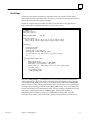
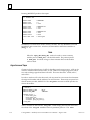
The source file for the demonstration is \PCMC\EXAMPLES\HELLO.C, which was
copied to your hard disk during the PCM C toolkit installation. Open it with your text
editor; it should look like this:
/*
* HELLO.C
*
* PCM C demonstration program
*/
#include <vtos.h>
#include <stdio.h>
void main()
{
word task, rev;
task = Get_task_id();
rev = Get_pcm_rev();
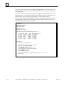
printf( ”Hello, world!\n” );
printf( ”I’m running as task %02x hex under VTOS version %x.%02x.\n”,
task, rev >> 8, rev & 0xff );
}
If you prefer, you can type it into your editor.
The program prints its greeting and some information about where it is running. It calls
three library functions: Get_task_id and Get_pcm_rev from the PCM libraries,
and the standard library function printf.
GFK -0771A
3-1
3
Compiling Sources
An MS-DOS batch file, CC.BAT, is provided for compiling single source files. Using it is
the most convenient way to compile one or two sources. The command line for using it
is simply:
cc <memory model> <file name>
where <memory model> specifies the memory model you want to use, and <file name>
is the name of your source file without the file extension or dot (’.’) character. You can
specify either “s”, “m”, or “l” (for Small, Medium, and Large, respectively) as the memory
model. “S”, “M”, and “L” have the same meaning. Compiling in Small model produces
smaller, faster code. You should specify “s” or “S” whenever possible. For more
information on memory models, see chapter 8, Memory Models.
To compile our example,firstcopy\PCMC\EXAMPLES\HELLO.C to a working directory.
Then, type: cc s hello at the MS-DOS prompt, and press the Enter key. You should see
this on your screen:
Microsoft (R) C Optimizing Compiler Version 6.00A
Copyright (c) Microsoft Corp 1984–1990. All rights reserved.
hello.c
>
If you see:
Bad command or file name
>
your PCM C toolkit has not been installed correctly. Please review the steps in chapter 2,
Installation.
Compiling C code for the PCM requires the use of several Microsoft C Compiler
command line switches. CC.BAT remembers all of them for you. One of these switches
produces a log file (for example, HELLO.OUT). When the compiler issues error or
warning messages, they are placed in the log file. After compilation completes, the log
file is displayed on your screen. If you see error messages, you can open the log file in
your text editor while correcting the C source file.
3-2
C Programmer’s Toolkit for Series 90 PCMs User’s Manual – August 1996
GFK-0771A
3
Linking Objects
After compiling to the object (.OBJ) files, C programs must be linked with Microsoft and
PCM library functions to produce an executable (.EXE) file. Linking for the PCM also
requires several command line switches. To make it simple, another MS-DOS batch file,
CLINK.BAT, is provided for linking a single object file. Its use is similar to CC.BAT:
clink <memory model> <file name>
where the same <memory model> and <file name> used with CC.BAT must be used
again. Typing: clink s hello produces:
Microsoft (R) Segmented–Executable Linker Version 5.10
Copyright (C) Microsoft Corp 1984–1990. All rights reserved.
>
If there are linkage errors, the linker will display error messages between its invocation
message and the MS-DOS prompt.
CLINK.BAT accepts up to five object files. If your application requires six or more source
files, see “Using Makefiles” later in this chapter.
Specifying the Stack Size
Unlike standard MS-DOS, the PCM executes applications in ROM (Read-Only Memory)
as well as RAM (Random Access Memory, which can be read and written). One
consequence of this feature is that the PCM cannot use the MS-DOS method for
specifying program stack size. Instead, each PCM .EXE file has a data value in its header
which contains the stack size. MS-DOS uses this data for a different purpose, and the
Microsoft linker always initializes the PCM stack size to 65,520 bytes. This is a very large
stack for most applications, and wastes PCM memory.
A PCM C utility program, STKMOD.EXE, is used to specify the correct stack size.
Note
The Microsoft compiler and linker command line switches for specifying
the stack size of MS-DOS executable files have no effect when used for
PCM C applications. The STKMOD utility must be used instead.
GFK-0771A
Chapter 3 Creating and Running PCM C Programs
3-3
3
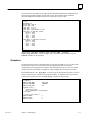
The STKMOD command line is
stkmod <exe name> –s <decimal stack size in bytes>
or
stkmod <exe name> /s <decimal stack size in bytes>
where <exe name> is the .EXE file name, with or without the file extension and dot (’.’)
character, and <decimal stack size in bytes> specifies the stack size.
To specify a 2 Kbyte stack for HELLO.EXE, type: stkmod hello –s 2048 at the MS-DOS
prompt. STKMOD responds with:
GE Fanuc Automation PCM EXE File Stack Size Utility, Version 1.00
Copyright (c) 1992, GE Fanuc Automation North America, Inc.
All rights reserved.
HELLO.EXE
(hex)
(dec)
new stack size in paragraphs
new stack size in bytes
0080
0800
128
2048
which shows that the stack size is now 800 hexadecimal (or 2048 decimal) bytes.
A stack size of 2048 bytes is ample for most PCM applications, although some will
require more.
The minimum PCM stack size is 1024 bytes, and the maximum size is 65,520. Valid stack
sizes are integer multiples of 16 bytes. If you specify a stack size which does not meet
these requirements, STKMOD.EXE will adjust it for you.
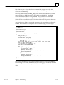
The STKMOD utility can also be used to check the stack size of PCM .EXE files without
changing it. Simply invoke STKMOD without a stack size value. If you type: stkmod
hello, STKMOD responds with:
GE Fanuc Automation PCM EXE File Stack Size Utility, Version 1.00
Copyright (c) 1992, GE Fanuc Automation North America, Inc.
All rights reserved.
3-4
HELLO.EXE
(hex)
(dec)
old stack size in paragraphs
old stack size in bytes
0080
0800
128
2048
C Programmer’s Toolkit for Series 90 PCMs User’s Manual – August 1996
GFK-0771A
3
Loading Executable Files
Executable files must be loaded to the PCM using TERMF, the PCM terminal
emulation/file transfer program. TERMF is available separately from GE Fanuc
Automation as catalog number IC641SWP063. For information on TERMF installation
and configuration, see chapter 2, section 3, “TERMF installation and Configuration”, in
the Series 90 Programmable Coprocessor Module and Support Software User’s Manual,
GFK-0255D or later.
If you already have a copy of PCOP, the PCM development software package (catalog
number IC641SWP061), you do not need to purchase TERMF separately. TERMF is a
part of the PCOP package; it can be invoked from within PCOP with the Shift-F3
function key. Alternatively, TERMF can be started without PCOP by typing:
\PCOP\TERMFat the MS-DOS prompt. If the \PCOP directory is in your PATH, you
can simply type: TERMF.
Before a program can be loaded to a Series 90-30 PCM, it must be configured for either
PCM CFG or PROG PRT mode. The configuration can be performed using either the
Series 90-30 Hand-Held Programmer or the Logicmaster 90-30 configuration software
package.
Caution
When a Series 90-30 PCM has not been configured by either the
Hand-Held Programmer or Logicmaster 90-30 software, its default
configuration mode is CCM communication on both serial ports. You
will not be able to load or run PCM programs until the PCM has been
configured for PCM CFG or PROG PRT mode.
Programs can be loaded to a Series 90-70 PCM without configuring it using Logicmaster
90-70 configuration software.
An RS-232C serial port on your computer (PC) must be connected to serial port 1 of the
PCM by an appropriate serial cable. RS-232C cables for common PC serial ports are
described in appendix A of the Series 90 Programmable Coprocessor Module and Support
Software User’s Manual, GFK-0255D, or later.
The serial communication settings for TERMF must be identical to the ones used by the
PCM. When the PCM is configured for Logicmaster 90 PCM CFG mode, the settings are
19,200 baud, no parity, eight (8) data bits, one (1) stop bit, and hardware handshaking.
In PROG PRT mode, the settings are selected by the user.
Note
PCM file transfer requires 8 data bits and hardware handshaking. File
transfers will fail if 7 data bits or software handshaking is selected.
The TERMSET program, included with both the TERMF and PCOP software products,
may be used to specify TERMF serial communication settings. See “Using TERMSET to
Configure TERMF or PCOP” in chapter 2, section 3 of the Series 90 Programmable
Coprocessor Module and Support Software User’s Manual, GFK-0255D or later.
GFK-0771A
Chapter 3 Creating and Running PCM C Programs
3-5
3
When you have connected your PC’s serial port to the PCM, configured TERMF, and run
it from the MS-DOS prompt, reset your PCM by pressing the Restart/Reset button and
holding it for more than five (5) seconds (a hard reset). If you press the Enter key on
your PC, you should see the “>” prompt from the PCM command interpreter. Pressing
the Enter key repeatedly should add another “>” prompt on the same line each time
you press it.
The command interpreter defaults to its non-interactive mode, which is used by PCOP.
However, loading and running C applications is much easier in interactive mode. Type
two exclamation points (“!!”) and press the Enter key to switch to interactive mode. You
should see this message:
INTERACTIVE MODE ENTERED
type ’?’ for a list of commands
>
Once again, the “>” character is the PCM prompt. If you press the Enter key at this
point, you should see another “>” prompt, separated from the first one by a blank line.
If you have trouble communicating with your PCM or getting into interactive mode,
refer to appendix B, PCM Commands. Appendix B also includes a complete reference for
PCM commands.
When TERMF is communicating with the PCM command interpreter in interactive
mode, and HELLO.EXE is in your PC’s current directory, you are ready to load it to the
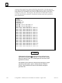
PCM. Use the PCM L (Load) command; type: L HELLO.EXE at the PCM prompt. You
should see the middle LED on the PCM flash while the file is being loaded. When the file
transfer has completed, another blank line and “>” prompt will be displayed. Verify that the
file was loaded by using the PCM D (Directory) command. HELLO.EXE should be one of the
files listed:
>
dHELLO.EXE
0616:00A0
The hexadecimal numbers which follow the the file name are its entry point address.
Entry points are shown only for executable files, and only if your PCM has firmware
version 3.00 or later. Entry point addresses are useful for debugging C programs with
hardware debuggers and for interpreting the output of the PCMDUMP utility. See
chapter 11, Utilities, for information on the PCMDUMP utility.
3-6
C Programmer’s Toolkit for Series 90 PCMs User’s Manual – August 1996
GFK-0771A
3
Running a PCM Task
The PCM R (Run) command is used to execute an .EXE file as a PCM task. At the PCM
prompt, type: R HELLO.EXE.
The file extension “.EXE” is required by the PCM command interpreter.
When the program is executed, TERMF will display its output:
Hello, world!
I’m running as task 0f hex under VTOS version 3.00.
The Run command can also be used to load PCM programs from your PC. If the
specified .EXE file has not been stored to the PCM, the command interpreter will ask
TERMF to look in the current PC directory. If the file is found there, it will be loaded and
then run.
Debugging a PCM Task
PCM firmware version 3.00 does not include a runtime debugger. The best debug
method currently available is to use printf statements to trace program execution and
display program data. Applications which use both PCM serial ports for communication
can log execution trace data to a PCM file or named memory module.
Series 90-70 PCM applications can log trace data to a reserved memory block in VME
dual port memory. A second PCM can be used to read the data in VME master mode.
When an application task locks up, the PCM task state dump facility can be used to
diagnose the cause. For more information on this topic, see “Dumping PCM task state
information” in chapter 7, Multitasking.
Some developers of PCM C applications use hardware debuggers. See “Debugging
Multiple Tasks” in chapter 7, Multitasking, for more information on hardware debuggers.
GFK-0771A
Chapter 3 Creating and Running PCM C Programs
3-7
3
Using Makefiles
Building PCM .EXE files from two or more C sources, and building multitasking
applications (with two or more .EXE files) is handled most efficiently by using either the
NMAKE or NMK utility provided with Microsoft C. NMK is provided with Microsoft C
6.0, but not with Microsoft C/C++ 7.0. Some restrictions apply to NMK. See the
Microsoft documentation for information on using NMAKE and NMK.
When using one of these utilities to build PCM applications, the command line options
which NMAKE or NMK uses to invoke the Microsoft compiler and linker must be
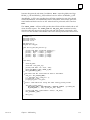
specified correctly. The file MAKEFILE.1, which was copied to your \PCMC\EXAMPLES
directory during installation of the PCM C toolkit, builds HELLO.EXE. You can use it by
deleting all the HELLO.* files except HELLO.C from your working directory, and then
typing:
NMAKE \PCMC\EXAMPLES\MAKEFILE.1
or
NMK \PCMC\EXAMPLES\MAKEFILE.1
at the MS-DOS prompt. NMAKE or NMK should respond with:
Microsoft (R) Program Maintenance Utility
Version 1.11
Copyright (c) Microsoft Corp 1988–90. All rights reserved.
cl /c /AS /Aw /G1 /Gs /FPa /Zl /Zp /Fchello hello.c >hello.out
Microsoft (R) C Optimizing Compiler Version 6.00A
Copyright (c) Microsoft Corp 1984–1990. All rights reserved.
type hello.out
hello.c
link /NOD/NOE/M crt0sm hello.obj chkstks ifcallsm, hello.exe, hello.map,
apis+pcms+slibca;
Microsoft (R) Segmented–Executable Linker Version 5.10
Copyright (C) Microsoft Corp 1984–1990. All rights reserved.
When the MS-DOS prompt appears, all the steps for building HELLO.EXE have been
completed.
3-8
C Programmer’s Toolkit for Series 90 PCMs User’s Manual – August 1996
GFK-0771A
3
MAKEFILE.1 may be used as a pattern for makefiles which build other applications. Just
change the OBJLIST macro and target .EXE file name appropriately. For example, to
build a PCM application called myapp.exe from the sources myapp1.c, myapp2.c, and
myapp3.c use:
OBJLIST=myapp1.obj myapp2.obj myapp3.obj
.
.
.
myapp.exe : $(OBJLIST)
Note
As the total number of characters in the OBJLIST macro definition
increases, the LINK command line issued by NMAKE or NMK will
eventually exceed the MS-DOS command length limit. When this
happens, linker errors will occur. The remedy is to use a linker response
file for long command input. See the Microsoft LINK documentation.
For more information on makefiles, NMAKE and NMK, see the Microsoft C
documentation.
GFK-0771A
Chapter 3 Creating and Running PCM C Programs
3-9
Chapter
4 Using PCM Resources
4
section level 1 1
figure bi level 1
table_big level 1
t
The GE Fanuc Series 90 Programmable Coprocessor Module (PCM) family provides a
platform within Series 90 PLCs for C applications developed by OEMs and system
integrators. This chapter is an overview of the resources provided by PCMs and PLC
CPUs.
PCM Hardware Resources
Each PCM is equipped with 128 to 640K bytes of RAM, 256K bytes of EPROM (128K
bytes of which is dedicated to system firmware), two high performance serial ports, a
PLC backplane communication channel to the PLC CPU, three programmable timers,
and three programmable light emitting diode (LED) indicators (two of which may be
programmed by applications).
In addition to communication between the PCM and PLC CPU, the PLC backplane
communication channel supports communication between two or more PCMs in the
same PLC. Series 90-70 PCMs can also operate as VMEbus masters to read and write
VMEbus memory in other PLC modules.
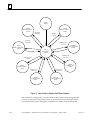
The VTOS Operating System
VTOS is a small, real-time, multitasking operating system which runs on the PCM family
of products. It provides system services to C applications. VTOS is optimized for
process control, communications, and operator interface applications on the Intel 80186
and 80188 processors.
VTOS provides these key features:
GFK-0771A
D
A pre-emptive scheduler supports both priority-based and time-slice scheduling of
application tasks.
D
The majority of system services are implemented in assembly language to minimize
execution times.
D
Event flags, semaphores, shared memory, and asynchronous traps are provided for
inter-task communication.
D
A real-time clock provides up to 256 programmable timers with one millisecond
resolution and a seven-week range.
4-1
4
D
A device manager provides access to the serial ports; files stored in RAM, ROM, or
the disk drives of an attached PC; and backplane access to Series 90-70 and 90-30
PLC CPUs as well as other PCMs in the same PLC. A consistent interface is provided
for all devices, which is similar to asynchronous I/O under UNIX:
H Each task has predefined standard input, output and error channels which can
be redirected to any device;
H Tasks can open channels to any PCM device;
H I/O can proceed asynchronously to task execution;
D
The VTOS memory manager and PCM battery-backed RAM allow user programs
and data to be retained in memory through power outages.
D
A fast runtime memory manager allocates memory blocks in as little as 50
microseconds.
D
A command interpreter loads and runs user tasks and controls their execution
environment.
D
A batch file facility starts applications automatically when the PCM powers up or is
reset.
D
VTOS supports user programs in EPROM.
These services are built into the PCM firmware. A small library of interface functions
provides access from application code.
The VTOS File System
Files in the PCM are stored in either RAM, EPROM, or EEPROM (in the PCM 301 only).
Consequently, there are some important differences between VTOS files and files in a
disk operating system:
1.
Disk file systems are based on magnetic storage media, which have an inherent
block structure based on disk tracks and sectors. VTOS files, however, are structured
at the lowest level as sequential files of bytes, or stream files.
PCM C developers may choose to impose their own block structure on the data in
VTOS files. VTOS provides services for random access to files.
2.
Data read and write operations on magnetic media are inherently slow. Disk file
systems use buffering to minimize the impact on applications. When an application
writes data to a file, the data is actually put into a file buffer in memory. Closing the
file is often the only way to force the file system to move all the data to the disk and
update the file directory with the correct file size.
One result is that data may be lost when an application ‘‘hangs’’. Under MS-DOS,
for example, recovering from a hung application often requires a warm boot
(Ctrl-Alt-Delete reset). If the application opened a new output file but did not close
it before hanging, the file size will be zero (0) after the warm boot.
VTOS files are not buffered. Because read and write operations are performed
directly on RAM or ROM, buffering would actually make them slower. Each write
operation at the end of a file adds the new data and updates the file size. If the
application should hang, all the data it wrote will be in the file.
4-2
C Programmer’s Toolkit for Series 90 PCMs User’s Manual – August 1996
GFK-0771A
4
The PCM Command Interpreter
The user interface to the PCM is a command interpreter which is conceptually similar to
the MS-DOS command line interpreter or the Unix shell. The PCM command
interpreter allows the user to download application programs and run them, and
provides many other commands which are listed in appendix B, PCM Commands. The
interpreter also supports batch files, which are described in appendix C, Batch Files. A
special startup batch file named PCMEXEC.BAT can be used to run applications
automatically on power-up or reset.
By default, the command interpreter uses PCM serial port 1 (COM1:) as its input and
output device. However, it can be redirected to serial port 2 (COM2:) or the PLC
backplane device (CPU:). It can communicate with any character mode device.
Accessing PLC Data From PCM Programs
Data from the PLC CPU is almost always an important part of PCM applications. There
are four ways PCM programs can access PLC data:
1.
The VTOS Open_dev, Read_dev, Write_dev, and Close_dev services;
2.
PLC API services;
3.
COMMREQ messages from PLC programs; and
4.
Series 90-70 VME function blocks.
PCM applications can use any or all of these methods, except that VME function blocks
are available only in Series 90-70 PCMs. The following sections provide an overview of
each of these methods.
VTOS CPU: Device Services
The built-in VTOS device driver for the PC: device supports I/O operations between
PCM applications and PLC data. PCM applications can open I/O channels to all PLC
global data references. Each channel must be opened by calling the Open_dev function
and specifying a device name of the form “CPU:%<r ef_letter> ”, where <r ef_letter> is a
single letter that specifies a PLC memory reference type.
PLC API Services
Series 90 PLCs provide a rich set of services which are accessible from PCMs. The PLC
service request Application Program Interface (API) library provides convenient function
calls to:
GFK-0771A
1.
Open a PLC API session with the PLC CPU;
2.
Determine PLC operational status;
3.
Determine the PLC CPU hardware type and data sizes;
4.
Obtain the PLC user program and configuration data checksums;
5.
Read the I/O and PLC fault tables;
6.
Check Series 90-70 PLCs for faulted racks, modules, Genius busses, and Genius
devices;
Chapter 4 Using PCM Resources
4-3
4
7.
Clear the I/O and PLC fault tables;
8.
Read collections of mixed PLC data references;
9.
Change the PLC access privilege level;
10. Read and write PLC data references;
11. Read and write Series 90-70 Program (%P) and Local (%L) data;
12. Read and set the PLC time-of-day clock; and
13. Start and stop PLC program execution.
For more information on PLC API services, see chapter 5, PCM Libraries and Header Files.
Communications Request (COMMREQ) Messages From PLC Programs
PLC programs can send messages to PCM programs with COMMREQ function blocks.
Each COMMREQ message can include up to 128 words (256 bytes) of PLC data.
COMMREQ data must be a contiguous block from a single, word-oriented, PLC
reference type (%R, %IA, or %AQ in both Series 90-70 and Series 90-30 COMMREQs
plus %P or %L in Series 90-70 COMMREQs only). Discrete PLC data types may not be
transferred directly as COMMREQ data. However, they can be copied to a
word-oriented type and then transferred by a COMMREQ.
COMMREQ function blocks may be programmed for either WAIT mode or NOWAIT
mode. In WAIT mode, the PLC CPU sends a COMMREQ message and waits for a reply
from the target PCM before ladder program execution continues. In NOWAIT mode,
ladder execution continues immediately after the COMMREQ message is sent.
Caution
NOWAIT mode should always be used, because WAIT mode
COMMREQs can significantly degrade PLC sweep time. In addition,
WAIT mode COMMREQs can cause the PLC watchdog timer to expire,
halting PLC program execution.
4-4
C Programmer’s Toolkit for Series 90 PCMs User’s Manual – August 1996
GFK-0771A
4
Programming COMMREQ Function Blocks
COMMREQ function blocks have four inputs. Series 90-30 COMMREQs have one output, while
Series 90-70 COMMREQs have two.
(enable) –
COMM_
REQ
???????– IN
– (ok, Series 90-70 only)
FT
???????– SYSID
???????– TASK
IN:
This parameter specifies the PLC memory location where the COMMREQ command
block begins; for example, %R00001. The COMMREQ command and data blocks must
occupy contiguous areas within one of the word-oriented PLC data types listed above.
The command block is described in the next section.
SYSID:
This parameter species the rack and slot address of the target PCM. Logicmaster 90
software displays SYSID as a hexadecimal value. Its most significant byte must contain
the rack number of the target PCM, and the least significant byte must contain the slot
address. For example, the value 0102 hexadecimal specifies rack 1, slot 2. Note that
Series 90-30 PCMs must be installed in rack zero.
If SYSID does not specify a rack/slot address where a PCM or other Series 90 module
capable of receiving COMMREQs is installed, no COMMREQ will be sent when the
function block is enabled, and the function block FT output will become active.
TASK:
This parameter species the ‘‘task’’ or service point in the target PCM where the
COMMREQ will be delivered. This value is not equivalent to the VTOS task number of
the destination task. Instead, it is the numeric value specified in the device name string
passed to a call by the VTOS Open_dev function:
word commreq_handle;
commreq_handle = Open_dev( “cpu:#<number>”, ...
where commreq_handle is a VTOS handle for the device I/O channel where
COMMREQs will be received, and <number> is the service point value for that channel.
Service point values must be in the range 4 through 120 decimal. Note that values
outside this range are either invalid or reserved for use by VTOS.
A PCM task may open more than one service point for COMMREQ messages.
GFK-0771A
Chapter 4 Using PCM Resources
4-5
4
Caution
Logicmaster 90 software displays this parameter in hexadecimal
format, while Open_dev expects service point values in device name
strings to be specified in decimal format. The same value must be
used for both; otherwise the COMMREQ message will not be
delivered to the target task, and an Invalid Task fault will be posted to
the PLC fault table.
The safest technique is to enter the COMMREQ TASK value in decimal format on the
Logicmaster 90 input line. Before pressing the Enter key to accept the value, verify
visually that is the same one used in the Open_dev device name.
OK and FT:
The OK and FT (fault) outputs can provide power flow to optional logic to verify that
the COMMREQ was sent successfully. Note that Series 90-30 COMMREQ function
blocks have no OK output. OK and FT can have these states:
Enable
Error?
OK Output
FT Output
Active
Active
Not active
No
Yes
No execution
TRUE
FALSE
FALSE
FALSE
TRUE
FALSE
In NOWAIT mode, a COMMREQ function block with a valid SYSID always passes
power flow to the OK output whenever it executes.
The FT output becomes active in NOWAIT mode if:
1.
There is no PCM or other intelligent module in the rack and slot specified by the
SYSID input.
2.
The data length specified in the command block is zero or greater than128 words.
The COMMREQ Command and Data Blocks
The command block provides additional information about the COMMREQ message
needed by the COMMREQ function block.
The address of the command block is provided to the IN input to the COMMREQ
function. This address may be in any word-oriented PLC reference (%R, %AI or %AQ in
both the Series 90-70 and Series 90-30 COMMREQ; %P or %L in the Series 90-70
COMMREQ only). The length of the command block is always 6 words. The
COMMREQ data must immediately follow the command block, in the same reference
table.
4-6
C Programmer’s Toolkit for Series 90 PCMs User’s Manual – August 1996
GFK-0771A
4
The command block has the following structure:
Data Block Length
Start address +0 (word 1)
Wait/NoWait Flag
Start address +1 (word 2)
Status Pointer Memory Type
Start address +2 (word 3)
Status Pointer Offset
Start address +3 (word 4)
Idle Timeout Value
Start address +4 (word 5)
Maximum Communication Time
Start address +5 (word 6)
Data Block
Start address +6 (word 7)
through
Start address +133 (word 134)
Information required for the command block can be placed in the designated memory
area using the MOV or BLKMOV function block.
When entering information for the command block, refer to these definitions:
Data Block
Length:
This word contains the number of data words starting at address +6 (word 7) to the end
of the data block, inclusive. The data block length ranges from 1 to 128 words.
Wait/Nowait
Flag:
This word selects whether or not the program should wait for the COMMREQ to be
acknowledged by the PCM before the PLC sweep continues. This word should always
be set to zero to select NOWAIT mode.
Status Pointer The two status pointer words specify a PLC memory location where the target PCM is
Memor y Type: expected to write a status word. Status Pointer Memory Type must contain a numeric
word value that specifies the PLC memory reference type for the status word location.
The table below shows the code for each reference type:
Status Pointer Memory Type:
For This Memory Type
%I
%Q
%R
%AI
%AQ
Discrete input table
Discrete output table
Registermemory
Analog input table
Analog output table
Use This Value
16
18
8
10
12
The most significant byte of the word value at address +2 should contain zero.
GFK-0771A
Chapter 4 Using PCM Resources
4-7
4
Status Pointer The word at address +3 contains the zero–based offset for the status word location
within the selected memory type. For example, %R00001 is at offset zero in the register
Offset:
table. %R00300 is at offset 299.
Idle Timeout
Value:
The idle timeout value is the maximum time the PLC CPU waits for the target PCM to
acknowledge receipt of the COMMREQ. This value is ignored in NOWAIT mode.
Maximum
Communication Time:
The value at address +5 specifies the maximum time the PLC CPU waits for the target
PCM to complete the COMMREQ. This time is also ignored in NOWAIT mode.
Data Block:
The COMMREQ data block contains all the data which the PLC CPU will send to the
target PCM with the COMMREQ message. The data size, in words, is specified by the
Data Block Length value, described above.
Receiving COMMREQ Messages In a PCM Program
PCM C applications receive COMMREQ messages by calling Open_dev to open an I/O
channel on the CPU: device for reading, and then calling Read_dev to copy each
COMMREQ message to a program variable.
The following program fragment opens a channel using a service point it calculates by
adding ten to its VTOS task number. Note that the VTOS device I/O operations in this
example use WAIT mode I/O to receive NOWAIT COMMREQs. There is no connection
between PLC CPU COMMREQ WAIT/NOWAIT modes and the notification mode used
by VTOS I/O.
4-8
C Programmer’s Toolkit for Series 90 PCMs User’s Manual – August 1996
GFK-0771A
4
#include <vtos.h>
#include <cpu_data.h>
#include <stdlib.h>
comreq_msg
char
word
word
word
word
word
word*
msg;
dev_name[] = ”cpu:#00”;
task_no;
commreq_handle;
read_size;
commreq_data_buffer[128];
commreq_data_size = 0;
commreq_data_ptr = NULL;
task_no = Get_task_id();
/* insert task number + 10 into device name string */
itoa( task_no + 10, dev_name + 5, 10 );
/* open an I/O channel to read COMMREQ messages */
commreq_handle = Open_dev( dev_name, READ_MODE, WAIT, task_no);
/* loop forever */
for (;;) {
/* clear the COMMREQ data size and pointer values */
commreq_data_size = 0;
commreq_data_ptr = NULL;
/* read a COMMREQ */
read_size = Read_dev( commreq_handle,
msg,
COMMREQ_MSG_SIZE,
WAIT,
task_no );
/* if a complete COMMREQ was read, extract the data */
if (read_size = COMMREQ_MSG_SIZE) {
/* test the COMMREQ message type byte */
if (msg.header.msg_type & 0x40) {
/* COMMREQ data is in the message; set the data size and pointer */
commreq_data_size = 6;
commreq_data_ptr = msg.data.short_c.data;
} else {
/* there is a separate COMMREQ data buffer; read it */
read_size = Read_dev( commreq_handle,
commreq_data_buffer,
msg.data.long_c.data_size,
WAIT,
task_no );
if (read_size == msg.data.long_c.data_size) {
/* all the data was read; set the data size and pointer */
commreq_data_size = read_size/2;
commreq_data_ptr = commreq_data_buffer;
}
}
}
}
The example opens a channel to read COMMREQ messages and then enters a
non-terminating loop to wait for COMMREQs. If a COMMREQ and its data are read
successfully, commreq_data_size contains the number of data words, and
commreq_data_ptr contains the address of an array of words containing the data. If
an error occurred, commreq_data_size contains zero.
GFK-0771A
Chapter 4 Using PCM Resources
4-9
4
Note that there are two formats for COMMREQ messages, depending on whether the
data size is 6 or fewer words (the short format) or more than 6 words (the long format).
Accordingly,\PCMC\INCLUDE\CPU_DATA.H contains a C union type definition,
comreq_msg, for COMMREQs. Both formats begin with a 16-byte header structure.
The header contains a msg_type member which can be tested to determine the
format of each COMMREQ message. COMMREQ messages with the 0x40 bit set
contain 6 or fewer data words. If the bit is not set, the COMMREQ has a separate data
buffer, and a second Read_dev call is used to get the data.
Note also that the COMMREQ message does not specify the data size when there are six
or fewer data words. If the data size can vary and must be known, the data should
specify its own size with a value in the first data word.
Responding to COMMREQs
The next program fragment illustrates the preferred method for returning a COMMREQ
acknowledgement to the PLC CPU. The status pointer type and offset values specified
in the COMMREQ command block are included in the COMMREQ message. This
example shows how to extract the status address from the message and write a status
value to it.
/*
* #include directives and data declarations from the previous example
* are not repeated here
*/
special_dev_8_type status_addr;
word
status_hndl;
word
commreq_status = 1;
/* open a channel for writing to the PLC status location */
/* the data type and offset are not important */
status_hndl = Open_dev( ”CPU:%R1”, WRITE_MODE, WAIT, task_no );
/* read a COMMREQ message as in example above (not repeated here) */
/* test the COMMREQ message type */
if (msg.header.msg_type & 0x40) {
/* COMMREQ data is in the message; get the status type and offset */
status_addr.type
= msg.data.short_c.status_type;
status_addr.offset = msg.data.short_c.status_offset;
} else {
/* separate COMMREQ data buffer; get the status type and offset */
status_addr.type
= msg.data.long_c.status_type;
status_addr.offset = msg.data.long_c.status_offset;
}
/* change the PLC data location of the status_handle channel */
Special_dev( status_handle, 8, &status_addr, 0, WAIT, task_no );
/* write a status value to the new location */
Write_dev( status_handle, &commreq_status, 2, WAIT, task_no );
The VTOS Special_dev function permits changing the PLC reference data type and
offset for a channel opened on the CPU:% device. This capability allows a channel to be
opened to a dummy reference address. The channel is then switched to the actual status
address for each COMMREQ.
4-10
C Programmer’s Toolkit for Series 90 PCMs User’s Manual – August 1996
GFK-0771A
4
Regulating the Timing of COMMREQ Messages
There are two COMMREQ timing issues: the time when the first COMMREQ for a
PCM task arrives, relative to task initialization; and the speed with which repeated
COMMREQs arrive.
The target PCM will reject a COMMREQ that is addressed to a valid service point if a
COMMREQ is sent before the PCM program has opened the service point. PLC ladder
programs must provide some mechanism for preventing COMMREQs from being sent
before the target PCM application is ready to receive them. In particular, a PLC power
cycle or brownout causes all the PCMs in the PLC to re-initialize themselves. The first
COMMREQ to any PCM must be delayed until the PCM has finished initialization,
VTOS has started the application tasks, and the application has opened the target
service point(s).
The simplest method for preventing a PLC program from sending COMMREQs before
the target PCM is ready to receive them is to start a timer on the first scan of the PLC
program. When a fixed time delay expires, program logic enables the COMMREQ
function blocks. The recommended delay is five seconds.
The PLC program folders \PCMC\EXAMPLES\DEMO_3T\PLC_30and
\PCMC\EX
AMPLES\DEMO_3T\PLC_70, installed with the PCM C toolkit, contain PLC
programs with timers to prevent COMMREQs during the first five seconds of program
execution.
The other COMMREQ timing issue concerns the speed at which COMMREQ messages
arrive. VTOS has a queue for messages which arrive from the PLC CPU. When a
COMMREQ message arrives, it is stored in this queue until the PCM application makes a
Read_dev function call to get it. When COMMREQs arrive more rapidly than
Read_dev calls are made, the queue eventually overflows. When overflow occurs, no
more COMMREQ messages can be received until a message slot in the queue is freed by
a Read_dev call. Until then, new messages are lost. The PCM posts a fault to the PLC
fault table whenever a message is lost.
Queue overflow can be avoided by designing the PLC program so that no more than
two COMMREQ messages are outstanding to each PCM in the PLC at any time. The
PLC programs in folders \PCMC\EXAMPLES\DEMO_3T\PLC_30and
\PCMC\EX
AMPLES\DEMO_3T\PLC_70 also contain logic which waits for the target
PCM to acknowledge each COMMREQ before the next one is sent.
GFK-0771A
Chapter 4 Using PCM Resources
4-11
4
Using Series 90-70 VME Function Blocks
Series 90-70 PLC ladder programs can also communicate with the PCM using the VME
Read (VMERD) and VME Write (VMEWRT) functions. These functions are not available
for Series 90-30 PLCs.
VMERD, VMEWRT, and other associated functions treat the PCM as a standard VMEbus
module. Data is moved to and from the PCM’s VMEbus dual port RAM.
VME functions usually execute faster than the equivalent COMMREQ for the same data
transfer. These functions can also be useful in situations when the PLC System
Communications Window must be severely shortened or eliminated.
However, VME functions lack many of the advantages of COMMREQs, including:
D
D
Guaranteed data coherency.
D
Fault reporting of some user programming errors, such as an invalid task or the
wrongrack/slot.
D
No requirement for user knowledge or manipulation of dual port addresses.
Automatic protection against simultaneous access to the same data location by the
PCM and PLC CPU.
Most applications should use COMMREQ function blocks to transfer data between the
ladder program and the PCM. VME functions should be used only when timing
constraints or other factors dictate their use.
VME Function Blocks for Communicating with the PCM
A group of PLC functions blocks is available in Logicmaster 90 software to allow a Series
90-70 PLC CPU to communicate with VMEbus modules, including the PCM. These
functions include:
D
D
D
D
VME Read (VMERD).
VME Write (VMEWRT).
VMERead/Modify/Write (VMERMW).
VME Test and Set (VMETS).
Each of these function blocks is discussed in detail later in this section.
Some Rules for VME Bus Operations in Series 90-70 PLCs
VMEbus block move transfers are not supported by Series 90-70 PLCs.
Do not install a PCM, or any other GE Fanuc Series 90-70 module, in a standard VMEbus
rack. Series 90-70 modules must be installed only in Series 90-70 PLC racks.
For more information about VME in the Series 90-70 PCM, refer to the Series 90-70
Programmable Controller User’s Guide to the Integration of Third Party VME Modules,
GFK-0448.
4-12
C Programmer’s Toolkit for Series 90 PCMs User’s Manual – August 1996
GFK-0771A
4
General VME Information for the PCM
When a PCM is the target module for VME functions, it should be configured with the
Logicmaster 90 configuration software in the same way it would be for non-VME
functions. The PCM should not be configured as a foreign VME module.
Addresses on the Series 90-70 VMEbus consist of two parts, an address modifier (AM)
code and a 24 bit address. The AM code consists of 6 bits and is used to select the target
Series 90-70 rack and the type of VME access (that is, the number of address bits used).
The AM code for a PCM is 39 hexadecimal. It specifies the Standard Nonprivileged access
type.
VME bus addresses for PCM modules used as VME function block targets depend on the
rack and slot location of the PCM. The PCM must be addressed in the range allocated to
the rack and slot where it is located. Address allocations for PCMs are provided in the
following table.
Table 4-1. GE Fanuc PCM Module Address Allocation
SlotNumber
Rack
Number
0
2
3
4
5
6
7
8
9
000000H
to
07FFFH
020000H
to
027FFFH
040000H
to
047FFFH
060000H
to
067FFFH
080000H
to
087FFFH
0A0000H
to
0A7FFFH
0C0000H
to
0C7FFFH
0E0000H
to
0E7FFFH
0
100000H through 7FFFFFH user-defined for rack 0 only.
1
E00000H
to
E07FFFH
E20000H
to
E27FFFH
E40000H
to
E47FFFH
E60000H
to
E67FFFH
E80000H
to
E87FFFH
EA0000H
to
EA7FFFH
EC0000H
to
EC7FFFH
EE0000H
to
EE7FFFH
2
D00000H
to
D07FFFH
D20000H
to
D27FFFH
D40000H
to
D47FFFH
D60000H
to
D67FFFH
D80000H
to
D87FFFH
DA0000H DC0000H
to
to
DA7FFFH DC7FFFH
DE0000H
to
DE7FFFH
3
C00000H
to
C07FFFH
C20000H
to
C27FFFH
C40000H
to
C47FFFH
C60000H
to
C67FFFH
C80000H
to
C87FFFH
CA0000H
to
CA7FFFH
CC0000H
to
CC7FFFH
CE0000H
to
CE7FFFH
4
B00000H
to
B07FFFH
B20000H
to
B27FFFH
B40000H
to
B47FFFH
B60000H
to
B67FFFH
B80000H
to
B87FFFH
BA0000H
to
BA7FFFH
BC0000H
to
BC7FFFH
BE0000H
to
BE7FFFH
5
A00000H
to
A07FFFH
A20000H
to
A27FFFH
A40000H
to
A47FFFH
A60000H
to
A67FFFH
A80000H
to
A87FFFH
AA0000H
to
AA7FFFH
AC0000H
to
AC7FFFH
AE0000H
to
AE7FFFH
6
900000H
to
907FFFH
920000H
to
927FFFH
940000H
to
947FFFH
960000H
to
967FFFH
980000H
to
987FFFH
9A0000H
to
9A7FFFH
9C0000H
to
9C7FFFH
9E0000H
to
9E7FFFH
7
800000H
to
807FFFH
820000H
to
827FFFH
840000H
to
847FFFH
860000H
to
867FFFH
880000H
to
887FFFH
8A0000H
to
8A7FFFH
8C0000H
to
8C7FFFH
8E0000H
to
8E7FFFH
In PCM address space, VMEbus memory is located in the range 0xA000:0x0000 to
0xA000:0x7FFF, regardless of the rack/slot location where the PCM is installed.
The Series 90-70 VMEbus data path is 16 bits wide. All Series 90-70 modules support 16
bit data access from the VMEbus. When more than one byte of data will be transferred,
the WORD data type should be specified for VME functions. WORD transfers move one
word per VME bus cycle, but BYTE transfers require two bus cycles to move a word.
GFK-0771A
Chapter 4 Using PCM Resources
4-13
4
PCM Dual Port RAM Available for Applications
The PCM system software uses a large part of the first 4000 hexadecimal bytes of the
PCM VMEbus dual port RAM. In addition, some PLC API library services require
VMEbus RAM.
Caution
Addresses within the first 4000 hexadecimal bytes of PCM VMEbus
memory should never be used as target addresses for VME functions.
Use only addresses at or above offset 4000 hexadecimal.
Future PCM enhancements are likely to use VMEbus memory above
the first 4000 hexadecimal bytes. Applications should use the highest
possible address for VME communication.
PCM C applications which use one or more blocks of VMEbus
memory should reserve them by calling the VTOS function
Reserve_dp_buff. This call should be made before any calls to
api_initialize. The return value from the Reserve_dp_buff
call should be tested to assure that the requested block of VME dual
port memory is available for the application.
4-14
C Programmer’s Toolkit for Series 90 PCMs User’s Manual – August 1996
GFK-0771A
4
VME Read Function
The VMERD function can be used to read data from the dual port RAM of a Series 90-70
PCM to the PLC CPU. This function should be executed before the data is needed in the
PLC ladder program.
The format of the VMERD function block is:
VME_
RD_
BYTE
address
modifier – AM
LEN
00001
module
address – ADR Q
(enable) –
Parameter
– destination for VME data
Description
Enable
Power flow input that, when TRUE, enables the execution of the function.
Type
Function type, either BYTE or WORD, to select the corresponding type of
VME bus access to be performed. WORD accesses transfer 16 bits of data
on each VMEbus cycle, while BYTE accesses transfer just 8 data bits per
bus cycle.
LEN
An internal parameter that, depending on the function type, specifies the
number of bytes or words to be transferred.
AddressModifier
A hexadecimal word value that specifies both the rack where the target
PCM is installed and the VMEbus access mode to be performed.
Module Address
A double word specifying the hexadecimal address where the first word or
byte is read from the VME bus. It may be a constant or the reference
address of the first (least significant) word of two words containing the
module address. The address is based on the rack and slot where the
PCM is located. (Refer to “Address Allocation by Rack and Slot” in this
section.)
OK
Q
GFK-0771A
– function OK (logic)
Power flow output that is TRUE when the function is enabled and
completessuccessfully.
Specifies the first PLC user reference location into which the data read
from the PCM is to be stored.
Chapter 4 Using PCM Resources
4-15
4
When the VMERD function receives power flow through its ENABLE input, the
function accesses the PCM at the specified address ADR and copies LEN data units
(words or bytes) from the PCM to PLC locations beginning at the output parameter Q.
When the operation is successfully completed, the VMERD function passes power to the
right through the OK output.
For information on PCM module addressing using addresses and address modifier
codes, refer to “General VME Information for the PCM,” presented earlier in this section.
Example VMERD Function
In this example, 128 words (256 bytes) of data are read from a PCM in rack 4, slot 7 into
registers %R00001 through %R00128 whenever enabling input %I00001 is TRUE. Unless
an error occurs while reading the data, output %Q00001 is set to TRUE.
|
_____
| %I00001
|
|
%Q00001
|–––] [–––––––––| VME_|––––––––––––––––––––––––––––––––––––––––––––––––––( )–
|
| RD_|
|
| WORD|
|
CONST –|AM
|
|
0039
| LEN |
|
|00128|
|
CONST –|ADR Q|– %R00001
|
0BA4000 |_____|
|
In Series 90-70 PCMs, VME dual port memory occupies 32K bytes. In PCM address
space, VME memory begins at address 0xA0000:0x0000, regardless of the rack and slot
where the PCM is installed. In this example, the VME bus address 0BA7000
hexadecimal corresponds to the PCM internal address 0xA000:0x7000.
There are several ways for PCM C programs to move data to this address in VMEbus
dual port RAM. One of the simplest is to use the standard C library memcpy function.
4-16
C Programmer’s Toolkit for Series 90 PCMs User’s Manual – August 1996
GFK-0771A
4
VME Write Function
The VMEWRT function can be used to write data from a Series 90-70 CPU to the VME
dual port RAM of the PCM. Locate the function block at a place in the program where
the output data is ready to send.
The format of the VMEWRT function block is:
VME_ – function OK (logic)
WRT_
BYTE
data to be
written – IN
LEN
00001
address
modifier – AM
(enable) –
module
address
– ADR
Parameter
Enable
Power flow input that, when TRUE, enables the execution of the function.
Type
Function type, either BYTE or WORD, to select the corresponding type of
VME bus access to be performed. WORD accesses transfer 16 bits of data
on each VMEbus cycle, while BYTE accesses transfer just 8 data bits per
bus cycle.
LEN
An internal parameter that, depending on the function type, specifies the
number of bytes or words to be transferred.
IN
Specifies the first PLC user reference location where the data to be written
to the PCM is stored. This parameter may be a constant, in which case the
constant value is written to all VME addresses covered by the function’s
length.
AddressModifier
A hexadecimal word value that specifies both the rack where the target
PCM is installed and the VMEbus access mode to be performed.
Module Address
A double word specifying the hexadecimal address where the first word or
byte is read from the VME bus. It may be a constant or the reference
address of the first (least significant) word of two words containing the
module address. The address is based on the rack and slot where the
PCM is located. (Refer to “Address Allocation by Rack and Slot” in this
section.)
OK
GFK-0771A
Description
Power flow output that is TRUE when the function is enabled and
completessuccessfully.
Chapter 4 Using PCM Resources
4-17
4
When the VMEWRT function receives power flow through its enable input, LEN data
units (words or bytes) from the PLC locations beginning at the input parameter IN are
written to the PCM at the specified address ADR. When the operation is successfully
completed, the VMEWRT function passes power to the right through the OK output.
For information on PCM module addressing using address and address modifier codes,
refer to “General VME Information for the PCM,” presented earlier in this section.
Example VMEWRT Function
In the following example, the hexadecimal value FFFF is written to each of 20 words on
the PCM during every sweep when enabling input %M00001 is TRUE. The starting
(lowest) PCM address is specified by the contents of %R00019 (low word) and %R00020
(high word). Unless an error occurs while writing the data, internal coil %M00055 is set
to TRUE.
|
|
_____
| %M00001
|
|
%M00055
|–––] [–––––––––| VME_|––––––––––––––––––––––––––––––––––––––––––––––––––( )–
|
| WRT_|
|
| WORD|
|
CONST –|IN
|
|
FFFF
| LEN |
|
|00020|
|
CONST –|AM
|
|
0039
|
|
|
|
|
|
%R00019 –|ADR |
|
|_____|
|
The PCM must be located in the rack and slot corresponding to the address contained in
%R00019 and %R00020. The PCM C application would read this data from the PCM
VMEbus dual port RAM by using, for example, a memcpy function call.
4-18
C Programmer’s Toolkit for Series 90 PCMs User’s Manual – August 1996
GFK-0771A
4
VME Read/Modify/Write Function
The VMERMW function can be used to update a data element in the dual port RAM of
the Series 90-70 PCM. Once the sequence of operations begins, the PCM will not be able
to access the data until the entire sequence has completed.
The format of the VMERMW function block is:
VME_ – function OK (logic)
RMW_
BYTE
operation – OP
(enable) –
data mask – MSK
address
modifier – AM
module
address
– ADR
Parameter
Enable
Power flow input that, when TRUE, enables the execution of the function.
Type
Function type, either BYTE or WORD, to select the corresponding type of
VME bus access to be performed. WORD accesses transfer 16 bits of data
on each VMEbus cycle, while BYTE accesses transfer just 8 data bits per
bus cycle.
Operation
A constant which specifies whether an AND or OR function is to be used
to combine the data and the mask. 0 specifies AND; 1 specifies OR.
Data Mask
A word value containing a mask to be ANDed or ORed with the data read
from the bus. If Type is BYTE, only the least significant 8 bits of the mask
are used.
AddressModifier
A hexadecimal word value that specifies both the rack where the target
PCM is installed and the VMEbus access mode to be performed.
Module Address
A double word specifying the hexadecimal address of the word or byte to
be accessed. It may be a constant or the reference address of the first (least
significant) word of two words containing the module address. The address
is based on the rack and slot where the PCM is located. (Refer to “Address
Allocation by Rack and Slot” in this section.)
OK
GFK-0771A
Description
Power flow output that is TRUE when the function is enabled and
completessuccessfully.
Chapter 4 Using PCM Resources
4-19
4
When the VMERMW function receives power flow through its enable input, the
function reads a word or byte of data from the module at the specified address (ADR)
and address modifier (AM). This byte or word of data is combined (AND/OR) with the
data mask (MSK). Selection of AND or OR is made using the input OP. If byte data is
specified, only the lower 8 bits of MSK are used. The result is then written back to the
same VME address from which it was read. When the operation is successfully
completed, the VMERMW function passes power to the right through the OK output.
For information on PCM module addressing using address and address modifier codes,
refer to “General VME Information for the PCM,” presented earlier in this section.
4-20
C Programmer’s Toolkit for Series 90 PCMs User’s Manual – August 1996
GFK-0771A
4
VME Test and Set Function
The VMETS function can be used to handle semaphores located in the VMEbus dual
port RAM of a Series 90-70 PCM. The VMETS function exchanges a boolean TRUE (1)
for the value currently at the semaphore location. If that value already was TRUE, then
the VMETS function does not acquire the semaphore. If the existing value was FALSE,
the semaphore is set and the VMETS function block has acquired control of the
semaphore as well as the memory area it controls. The semaphore is cleared and control
relinquished by using the VMEWRT function to write FALSE (0) to the semaphore
location.
The format of the VMETS function block is:
VME_
TS_
BYTE
address
modifier – AM Q
(enable) –
module
address
– semaphore acquired
– ADR
Parameter
Description
Enable
Power flow input that, when TRUE, enables the execution of the function.
Type
Function type, either BYTE or WORD, to select the corresponding type of
VME bus access to be performed. WORD accesses transfer 16 bits of data
on each VMEbus cycle, while BYTE accesses transfer just 8 data bits per
bus cycle.
AddressModifier
A hexadecimal word value that specifies both the rack where the target
PCM is installed and the VMEbus access mode to be performed.
Module Address
A double word specifying the hexadecimal address of the first word or byte
to be accessed. It may be a constant or the reference address of the first
(least significant) word of two words containing the module address. The
address is based on the rack and slot where the PCM is located. (Refer to
“Address Allocation by Rack and Slot” in this section.)
OK
Q
GFK-0771A
– function OK (logic)
Power flow output that is TRUE when the function is enabled and
completessuccessfully.
Set to TRUE if the semaphore was acquired. Set to FALSE if the semaphore
was not available, i.e., was owned by another task.
Chapter 4 Using PCM Resources
4-21
4
When the VMETS function receives power flow, a boolean TRUE is exchanged with the
data at the address specified by ADR using the address mode specified by AM. The
VMETS function activates the Q output if the semaphore was available and acquired by
the function. When the operation is successfully completed, the VMETS function passes
power to the right through the OK output.
For more information on Series 90-70 PLC programming, refer to the Logicmaster 90-70
Programming Software User’s Manual, GFK-0263, and the Series 90-70 Programmable
Controller Reference Manual, GFK-0265. For more information about Series 90-70 VME bus
applications, refer to the Series 90-70 Programmable Controller User’s Guide to the Integration
of Third Party VME Modules, GFK-0448.
C Program Access to PCM Dual Port RAM
VMEbus dual port RAM occupies the address range 0xA000:0x0000 through
0xA000:0x7FFF in the current hardware revision of the Series 90-70 PCM. VTOS and the
PLC API library use a part of this memory; the portion they use is at the low end of the
address range.
When VME function blocks are used for data PCM transfers, both the PLC and PCM
programs must know the location of a block of VMEbus memory. The application
designer usually chooses a location for this memory block before the programs are
written. However, it is possible for other PCM code to try to use the same memory
block. It is important for all PCM code which uses VMEbus memory to allocate or
reserve it through the VTOS Get_dp_buff or Reserve_dp_buff, respectively. If
these functions are used, VTOS will prevent VMEbus memory conflicts.
This example shows how to place a memory block for VME data transfers at the top end
of VMEbus dual port RAM, reserve it, and then free it when it is no longer needed.
The example assumes that the PLC CPU will use a VMEWRT function block to transfer
data to the PCM, and that the first data word is used as a lock to control access to the
data.
4-22
C Programmer’s Toolkit for Series 90 PCMs User’s Manual – August 1996
GFK-0771A
4
#include <vtos.h>
#include <dos.h>
#define VME_SIZE
#define VME_LIMIT
#define VME_OFFSET
word
void far*
char
(4 * 1024)
(32 * 1024)
(VME_LIMIT – VME_SIZE)
vme_available;
vme_ptr;
local_buff[VME_SIZE];
FP_SEG(vme_ptr) = 0xA000;
FP_OFF(vme_ptr) = VME_OFFSET;
vme_available = (Reserve_dp_buff( vme_ptr, VME_SIZE ) == SUCCESS);
if (vme_available) {
_disable();
while (*vme_ptr == 1) {
_enable();
Wait_time( MS_COUNT_MODE, 0, 5 );
_disable();
}
*vme_ptr = 1;
_enable();
memcpy( local_buff, vme_ptr, VME_SIZE );
*vme_ptr = 0;
}
Return_dp_buff( vme_ptr );
The Microsoft C header file DOS.H is included because it contains declarations of the
functions _disable and _enable, and definitions for the macros FP_SEG and
FP_OFF. These macros provide a simple method for assigning fixed addresses to far
pointers.
This example uses a 4K byte memory block. The macro definitions VME_LIMIT and
VME_OFFSET place it in the last 4K bytes of VMEbus memory. The segment and offset
values for the block are assigned to a far pointer, vme_ptr.
The memory block is reserved by passing its start address and size to
Reserve_dp_buff. If the call returns SUCCESS, vme_avail is set to one;
otherwise, vme_avail is set to zero.
If the block was reserved successfully, the code tests the lock word in VMEbus memory.
If the PLC CPU has control of the memory block, the code waits five milliseconds and
tests the lock again. A VMEWRT WORD transfer of 4K data bytes takes about five
milliseconds for a Series 90-70 Model 771 CPU. Note the _disable and _enable
function calls. They disable hardware interrupts while the code acquires control of the
lock byte. Without these calls, the task which executes this code could be pre-empted
after it tested the lock word but before it could be changed. Interrupts must be enabled
when Wait_time is called.
After the memory block is acquired, the data in it is copied to the array local_buf
and the lock byte is unlocked. Finally, the memory block is freed by calling
Return_dp_buff.
GFK-0771A
Chapter 4 Using PCM Resources
4-23
Chapter
5 PCM Libraries and Header Files
5
section level 1 1
figure bi level 1
table_big level 1
This chapter describes how the libraries and header files provided with the PCM C
toolkit are used to access PCM resources from C programs.
PCM Libraries
Two sets of libraries are furnished with the PCM C toolkit. Services provided by the
PCM’s VTOS operating system are accessed through the library files PCMS.LIB,
PCMM.LIB, and PCML.LIB for the small, medium, and large memory models,
respectively. PLC CPU services are provided by the PLC application program interface
(PLC API) library files APIS.LIB, APIM.LIB, and APIL.LIB for the small, medium, and
large memory models, respectively. The following sections describe VTOS and PLC API
services.
VTOS Interface
VTOS services are provided as system service function calls and global data. Some of
the services use predefined VTOS data types. The function calls, global variables, and
data types are all defined in the C header file VTOS.H.
Data types used by the PLC CPU which are returned to PCM applications or sent to the
CPU by VTOS device services are defined in CPU_DATA.H.
VTOS Services By Category
This section summarizes VTOS services by grouping them in categories of related
services. For full details on all VTOS services, refer to the PCM C Function Library
Reference Manual, GFK-0772.
Table 5-1. Task Management Functions
Function Name
Get_task_id
Init_task
GFK-0771A
Purpose
Returns the task ID value of the calling task.
Executes a VTOS device driver as a task.
Process _env
Starts a PCM task using a saved environment block.
Resume_task
Allows a task to execute.
Set_std_device
Sets a standard I/O channel for a task.
Suspend_task
Prevents a task from executing.
Terminate_task
Kills a task permanently and frees its resources.
Test_task
Returns the set of active tasks.
Wait_task
Waits for a specified task to terminate.
5-1
5
PCM applications, including these using multiple tasks, should be started from
PCMEXEC.BAT files. It is possible (but not recommended) to start one application task
from PCMEXEC.BAT and then start the others from the first by calling Init_task or
Process_env. A task’s ID value is required by many VTOS services and may be
obtained by calling Get_task_id. Task execution can be temporarily stopped by
Suspend_task and then started again by Resume_task. Test_task is used to
determine which task numbers are active, and Wait_task permits a task to wait until
a lower priority task terminates (for example, by exiting its main function).
Set_std_device reassigns the I/O channels assigned to the predefined STDIN,
STDOUT, and STDERR devices for a task, and Terminate_task permits a task to
terminate its own execution or that of another task. Note that Terminate_task is
called automatically when a task returns from its main function.
Event Flag Functions
Table 5-2. Event Flag Functions
Function Name
Purpose
Iset_ef
Sets one or more local event flags from an interrupt or communication
timer service routine.
Iset_gef
Sets one or more global event flags from an interrupt or communication
timer service routine.
Reset_ef
Resets one or more local event flags.
Reset_gef
Resets one or more global event flags.
Set_ef
Sets one or more local event flags.
Set_gef
Sets one or more global event flags.
Test_ef
Tests one or more local event flags.
Test_gef
Tests one or more global event flags.
Wait_ef
Waits for one or more local event flags to be set.
Wait_gef
Waits for one or more global event flags to be set.
Each PCM task has 16 local event flags which it can use to determine when external
events occur. There are also 16 global event flags shared by all PCM tasks. A task can
test its own local event flags, to determine whether one or more of them is set, using
Test_ef. A task can also clear one or more of its own local event flags using
Reset_ef. Any task can test or clear one or more global event flags by using
Test_gef or Reset_gef, respectively.
Any task may set the global event flags as well as local event flags for any task. Global
event flags should be set from communication timer timeout functions (see
Start_com_timer in the PCM C Function Library Reference Manual, GFK-0772) or
device drivers by calling Iset_gef. All other functions can set global event flags by
calling Set_gef. Similarly, local event flags should be set from communication timer
timeout functions or device drivers by calling Iset_ef, while other functions can set
them by calling Set_ef.
5-2
C Programmer’s Toolkit for Series 90 PCMs User’s Manual – August 1996
GFK-0771A
5
A task can wait for one or more global or local event flags to be set by external events by
calling Wait_gef or Wait_ef, respectively. Event flags should be reset before a task
waits for them; otherwise, Wait_gef or Wait_ef will return immediately if one of
the specified flags happens to be set.
Asynchronous Trap Functions
Table 5-3. Asynchronous Trap Functions
Function Name
Purpose
Disable_asts
Prevents the calling task from processing ASTs.
Enable_asts
Permits the calling task to process ASTs.
Post_ast
Sends an asynchronous trap to a specified task.
Wait_ast
Suspends execution of the calling task until an AST is received.
Asynchronous traps (ASTs) may be set for timer and device I/O events. See “Timer
Functions and Device I/O Functions,” below. A task may suspend execution and wait for
one or more traps to spring by calling Wait_ast. When the event occurs, an AST
handler function which was previously specified for that event is executed. After the
AST function returns, the Wait_ast function call which suspended the task also
returns, and the task resumes normal execution.
Tasks may prevent ASTs from being processed by calling Disable_asts, and may
resume AST processing by calling Enable_asts. A task may send an AST to itself or a
different task by calling Post_ast.
Semaphore Functions
Table 5-4. Semaphore Functions
Function Name
Purpose
Block_sem
Checks whether a semaphore is open; wait if not.
Link_sem
Links the calling task to a named semaphore; create one if it is not found.
If the semaphore already exists and is controlled by another task, the calling task waits.
Unblock_sem
Unlink_sem
Releases a semaphore, and activates the first waiting task.
Unlinks the calling task from a semaphore.
Two or more tasks can share memory modules (but not I/O channels) by using named
semaphores. A task may create a new named semaphore or use an existing one by
calling Link_sem. The task calls Block_sem before using the resource and then
calls Unblock_sem when it is finished. If the resource is available (that is, the
semaphore is “open”), execution proceeds immediately. However, if another task is
already using the resource (the semaphore is “closed”), execution is suspended until the
resource is available again.
GFK-0771A
Chapter 5 PCM Libraries and Header Files
5-3
5
Note that Link_sem leaves the semaphore closed. Unblock_sem must be called
after the Link_sem call. Typically, the controlled resource is accessed between calls to
Link_sem and Unblock_sem.
An unused semaphore can be freed by calling Unlink_sem, but this is rarely necessary.
One possible application might be for a semaphore used only during initialization when
PCM memory is tight.
Time-of-Day Clock Functions
Table 5-5. Time-of-Day Clock Functions
Function Name
Elapse
Purpose
Returns a count of milliseconds since the last time its count was reset.
Get_date
Returns the current date.
Get_time
Returns the current time of day.
Get_date and Get_time return the current date and time, respectively, from the
PCM time-of-day clock. The PCM clock is synchronized with the PLC time-of-day clock
once per second. The PLC time-of-day clock can be read directly by using read_date,
read_time, or read_timedate, described below.
Elapse returns a count of milliseconds since the last time it was reset by passing zero as
its parameter. The Elapse count is unaffected by PCM time-of-day clock
synchronization.
Caution
Do not use Get_time to calculate the time interval between two
events. The value returned by Get_time is affected by
synchronization of the PCM time-of-day clock with the PLC CPU. If
the PCM clock is re-synchronized with the PLC CPU between two
calls to Get_time, the calculated time interval will be incorrect.
Always use Elapse to determine time intervals. PCM clock
synchronization has no effect on Elapse.
5-4
C Programmer’s Toolkit for Series 90 PCMs User’s Manual – August 1996
GFK-0771A
5
Timer Functions
Table 5-6. Timer Functions
Function Name
Purpose
Cancel_timer
Stops a timer and undefines it.
Start_timer
Defines a timer and starts it counting from zero.
Wait_time
Suspends execution of the calling task for the specified time.
Up to 32 general purpose timers may be used by PCM applications. Timers are started
by calling Start_timer, and are programmed to expire after either a specified
number of days, hours, minutes, seconds, and milliseconds, or a specified long integer
number of milliseconds in the future. Timers may be programed to restart automatically
when they expire or for “one shot” operation. When the timer expires, a specified task
(usually the task which started the timer) is notified either by a local event flag or an
asynchronous trap. A timer which is running can be stopped by calling Cancel_timer.
A task may suspend its own execution for a specified time interval by calling
Wait_time. When the time expires, the Wait_time call returns.
Communication Timer Functions
Table 5-7. Communication Timer Functions
Function Name
Alloc_com_timer
Purpose
Allocates a communication timer to the calling task.
Cancel_com_timer
Stops a communication timer.
Dealloc_com_timer
De-allocates a communication timer.
Start_com_timer
Starts a previously allocated communication timer.
Four communication timers are available in the PCM. They require far less execution
overhead than general purpose timers, and are recommended when short time intervals
are required. A task must call Alloc_com_timer to reserve a communication timer
before it can be used. Communication timers are started by calling
Start_com_timer. The time interval is specified as milliseconds, and is limited to
65.535 seconds or less. When the timer expires, a timeout function, which was specified
as a Start_com_timer parameter, is called.
A running communication timer can be stopped by calling Cancel_com_timer.
Unused communication timers are freed by calling Dealloc_com_timer.
GFK-0771A
Chapter 5 PCM Libraries and Header Files
5-5
5
Memor y Management Functions
Table 5-8. Memory Management Functions
Function Name
Get_best_buff
Get_buff
Get_dp_buff
Purpose
Allocatesmemory from the smallest free memory block which is at least
as large as the requested size.
Allocatesmemory from the first free memory block which is at least as
large as the requested size.
Allocates memory from free VMEbus dual ported RAM in a Series 90-70 PCM.
Get_mem_lim
Returns the starting address of a memory block reserved for application
programs.
Max_avail_buff
Returns the size in bytes of the largest free memory block.
Max_avail_mem
Returns the total number of bytes in free memory.
Reserve_dp_buff
Reserves a specified block of VMEbus dual ported RAM in a Series 90-70
PCM.
Return_buff
Return_dp_buff
Returns the specified memory buffer to the free memory pool.
Returns the specified block of VMEbus dual ported RAM to the free
memory pool in a Series 90-70 PCM.
Two functions are provided for allocating blocks of free memory in PCM RAM. When
there are gaps in free memory, Get_best_buff searches the list of free blocks to find
the smallest one which fits the requested size. Get_buff allocates a buffer from the
first free block which is large enough. Get_buff is faster, but Get_best_buff is
recommended for applications which use many temporary buffers because it minimizes
free memory fragmentation. Note that the built-in I/O device drivers use temporary
buffers heavily.
Note
The standard C library function malloc is redefined in
PCMC\INCLUDE\MALLOC.Hand\PCMC\INCLUDE\STDLIB.Has
Get_buff. You may wish to modify these header files so that malloc is
redefined to be Get_best_buff.
A buffer which was allocated by either Get_buff or Get_best_buff may be
deallocated by calling Return_buff. If the returned buffer is adjacent to one or two
free memory blocks, they are consolidated. This is the PCM’s only runtime “garbage
collection” facility.
The total free memory size in bytes is returned by Max_avail_mem, and the largest
free block size is returned by Max_avail_buff.
Applications can call Get_mem_limit to determine whether PCM memory has been
partitioned to exclude some memory from VTOS by the command interpreter Y (Set
Upper Memory Limit) command. A pointer to the start of the excluded partition is
returned if there is one; otherwise, a NULL pointer is returned.
5-6
C Programmer’s Toolkit for Series 90 PCMs User’s Manual – August 1996
GFK-0771A
5
In Series 90-70 PCMs, a block of dual ported memory on the VMEbus can be allocated by
calling Get_dp_buff. Applications can also reserve a specified region of VMEbus
memory by calling Reserve_dp_buff. Applications which use VME dual ported
memory should call one of these services to avoid memory conflicts with PLC API
services and built-in backplane communication services. Unused VME dual ported
memory is freed by calling Return_dp_buff.
Memor y Module Functions
Table 5-9. Memory Module Functions
Function Name
Get_mod
Purpose
Returns the address of a named memory module.
A task may obtain the address of a named memory module by calling Get_mod. It
returns the far address of the mod_hdr structure at the start of the memory module.
Device I/O Functions
Table 5-10. Device I/O Functions
Function Name
Abort_dev
Aborts one or more I/O operations on a previously opened I/O channel.
Close_dev
Closes a previously opened I/O channel.
Devctl_dev
Performs a specified control operation on a named device.
Ioctl_dev
Performs a specified control operation on a previously opened I/O channel.
Open_dev
Opens a channel on a named I/O device.
Read_dev
Returns input data from a previously opened I/O channel.
Seek_dev
Positions the data pointer of a previously opened I/O channel to a specified
location.
Special_dev
Write_dev
GFK-0771A
Purpose
Performs a special operation on a previously opened I/O channel.
Sends output to a previously opened I/O channel..
Chapter 5 PCM Libraries and Header Files
5-7
5
The PCM supports I/O through named devices, and all devices use a common access
model. Presently, these devices are available:
Device Name
Description
COM1:, COM2:
The PCM serial ports.
REM1:, REM2:
The PCM backplane remote devices.
CPU:<object name>[,<qualifiers>]
The PCM backplane device.
RAM:
The PCM RAM disk file system.
ROM:
The PCM 301 EEROM device file system.
PC:
NULL:
The MS-DOS file system on an attached personal
computer.
A dummy device which does not support actual I/O.
For more information on specific PCM devices, see Open_dev in the PCM C Function
Library Reference Manual, GFK-0772.
A channel must be opened on a device by calling Open_dev before any I/O operations
may take place. Data is input from a device by calling Read_dev and output to a
device by calling Write_dev. When I/O operations on a channel are completed, it may
be closed by calling Close_dev.
The data pointer for an I/O channel may be set to a specified position by using
Seek_dev.
The Devctl_dev function may be used to format the PCM 301 EEROM device; delete
named files; return the names in a file directory; determine the unused file space
remaining in the EEROM device; set or clear AST notification of received serial breaks;
and set or clear the serial All Sent event flag.
Ioctl_dev can be called to determine whether a specified channel is a character or
file-oriented channel, whether the channel has input data available (and if so, how
much), whether the channel is ready for output data, and whether an ASCII ETX
(Ctrl-C) character has been received; to purge the channel’s input or output buffer; to
control serial port Send Break, RTS, and DTR status; and check Break Detect status.
Special_dev is used to determine the size of a file accessed through a specified
channel or set its maximum size, to specify passwords for PLC CPU data access, to set
serial port communication parameters, to set the Series 90 PLC rack/slot destination
address for backplane messages, to set files to read-only access mode, to set the memory
type and starting offset for PLC CPU data access, and to set high priority mode for
backplane messages.
Device I/O operations may be performed in WAIT, EVENT_NOTIFY, or AST_NOTIFY
mode. In WAIT mode, the function call does not return until the specified operation
completes. In EVENT_NOTIFY and AST_NOTIFY modes, the function call returns
immediately, and the task is notified of completion of the I/O operation by a local event
flag or AST, respectively. EVENT_NOTIFY and AST_NOTIFY modes are most useful for
operations which VTOS cannot complete immediately, such as Read_dev,
Write_dev, Seek_dev, and certain Devctl_dev and Special_dev operations
on the COM1:, COM2:, CPU:, PC:, REM1:, and REM2: devices.
Pending Device I/O operations may be cancelled by calling Abort_dev.
5-8
C Programmer’s Toolkit for Series 90 PCMs User’s Manual – August 1996
GFK-0771A
5
The function prototypes for these services in VTOS.H contain ellipses for the optional
NOWAIT mode parameters. When using EVENT_NOTIFY mode with any of these
functions in the small and medium memory models, the result_ptr parameter type
must be coerced to device_result far*. There are two ways it can be done. An
identifier which was declared as type device_result far* may be used.
Alternatively, the address of a structure may be passed by using an explicit type cast to
device_result far*. For example:
#include <vtos.h>
device_result far* p = Get_buff( size of (device_result) );
device_result result;
word task_id = Get_task_id();
Open_dev( ”COM1:”, WRITE_MODE, EVENT_NOTIFY, task_id, EF_01, p);
Open_dev( ”COM2:”, WRITE_MODE, EVENT_NOTIFY, task_id, EF_02,
(device_result far* )&result );
See “Small and Medium Model Differences Between VTOS and MS-DOS” in chapter 8,
Memory Models, for more information.
Caution
Failure to coerce the result_ptr parameter to far in small or
medium model will result in unexpected operation, possibly including
PCM lockup.
Device Driver Support Functions
Table 5-11. Device Driver Support Functions
Function Name
Get_next_block
Purpose
Returns device argument blocks to a VTOS device driver.
Install_dev
Installs a VTOS device driver.
Install_isr
Installs a VTOS interrupt service routine.
Notify_task
Notifies a VTOS task when a device operation completes.
These functions can all be used for installing and operating custom device drivers. A
future edition of this manual will discuss VTOS device drivers.
Install_isr may also be used to install software interrupt vectors so that two or
more tasks can share a single copy of library function code.
GFK-0771A
Chapter 5 PCM Libraries and Header Files
5-9
5
Miscellaneous Functions
Table 5-12. Miscellaneous Functions
Function Name
Define_led
Purpose
Defines the function of one of the programmable light-emitting diodes
(LEDs).
Get_board_id
Returns the PCM hardware type.
Get_pcm_rev
Returns the revision number of VTOS.
Set_dbd_ctl
Set_led
Sets the Series 90-70 PCM daughterboard control register.
Sets the state of one of the LEDs.
Set_vme_ctl
Sets the VMEbus access parameters in a Series 90-70 PCM.
Where_am_i
Returns the PLC rack/slot location of the PCM.
Define_led and Set_led are used to control the two programmable light-emitting
diodes (LEDs). Get_board_id may be used to determine the PCM hardware type
and memory size, Where_am_i is used to determine its Series 90 PLC rack/slot address,
and Get_pcm_rev returns the PCM firmware version.
Set_vme_ctl is used to access memory on the Series 90-70 VMEbus in bus master
mode, and Set_dbd_ctl is used to control custom Series 90-70 PCM daughter
boards, such as video controllers.
VTOS Macros
Two VTOS macros are provide to start and end a critical section in which PCM reset or
power fail processing will not occur. Critical sections are typically used for linked list
maintenance within PCM RAM modules or disk files. Because power fail processing
needs to be completed quickly, these macros save a little time by generating inline
assembly language instructions rather than using function calls.
Note
The total processing time between BEGIN_CRIT_SECT and
END_CRIT_SECT must be limited to 1 millisecond or less.
Caution
Do not make any VTOS function calls inside a critical section.
All accesses to data should be made through far pointers.
Table 5-13. VTOS Macros
Type Name
BEGIN_CRIT_SECT
END_CRIT_SECT
5-10
Purpose
Begins a critical section which will not be interrupted by power fail or
reset button events.
Ends a critical section, allowing power fail and reset processing to occur.
C Programmer’s Toolkit for Series 90 PCMs User’s Manual – August 1996
GFK-0771A
5
VTOS Types
These data types are defined in VTOS.H:
Table 5-14. VTOS Types in VTOS.H
Type Name
arg_blk
Passes information between the PCM device manager and device drivers.
ast_blk
Accesses arguments passed to an asynchronous trap (AST) handler
function.
code_hdr
Specifies additional information for executable memory modules.
dcb_blk
Controls data flow between the VTOS device manager and device
drivers. Each device has a unique device control block.
device_result
Accesses the completion status and return value of device I/O operations.
env_blk
Specifies the execution environment for executable memory modules.
long_ptr
Accesses the segment and offset parts of a far pointer, as an
alternative to the Microsoft C FP_SEG and FP_OFF macros.
mod_hdr
Describes each PCM memory module.
special_dev_8_type
GFK-0771A
Purpose
Defines the type and offset for PLC data references in the form used by
Special_dev when called with special_code=8.
Chapter 5 PCM Libraries and Header Files
5-11
5
These data types are defined in CPU_DATA.H:
Table 5-15. VTOS Types in CPU_DATA.H
Type Name
cmrq_union
A structure type component of comreq_msg. It defines the
COMMREQ union type and consists of both the short_cmrq and
long_cmrq structure types.
comreq_msg
Defines COMMREQ messages; it consists of msg_hdr and
cmrq_union members.
cpu_long_status
Defines the CPU long status structure returned by reading the
CPU:#LSTAT (CPU Long Status) device.
cpu_rt_clk
A structure type component of cp_sweep_info. It defines the CPU
scheduler clock structure type.
cpu_short_status
Defines the CPU short status structure type returned by reading the
CPU:#SST AT (CPU Short Status) device. It is approximately equivalent
to the PLC_STATUS_INFO_STRUC type defined in STATUS.H.
cpu_stat_flags
A structure type component of cpu_short_status. It defines the
PLC CPU status flags bit field structure, and is approximately
equivalent to the PLC_STATUS_WORD_STRUC type defined in
STATUS.H.
cp_sweep_info
A structure type component of cpu_long_status. It defines the PLC
sweep execution data structure.
cpu_tod
Defines the time and date structure type used to read or write the
CPU:#TOD (CPU Time-of-Day clock) device. It contains the current
day of the week, and is equivalent to the TIMESTAMP_LONG_STRUC
type defined in APITYPES.H.
cpu_tod_sclk
A structure type component of cpu_sweep_info. It defines the
short (no day of the week) time-of-day clock structure type used to
timestamp PLC program changes in cpu_long_status and is
equivalent to the TIMESTAMP_STRUC type, defined in APITYPES.H.
long_cmrq
A structure type component of cmrq_union. It defines COMMREQ
messages with msg_type values 0x82 and 0x83 (hexadecimal). These
COMMREQs have a separate data buffer.
msg_addr
Defines the bit field structure type which specifies the source and
destination of all PLC backplane messages as PLC rack/slot/task addresses.
It is used as a member of the msg_hdr type.
msg_hdr
Defines the common header structure used by all PLC backplane
messages, including COMMREQs.
short_cmrq
A structure type component of cmrq_union. It defines COMMREQ
messages with msg_type values 0xD2 and 0xD3 (hexadecimal). These
COMMREQs contain all their data within the message.
smemreq_msg
Defines the structure type used for read/write system memory service
requestmessages.
svcreq_msg
5-12
Purpose
Defines a generic service request message structure type.
C Programmer’s Toolkit for Series 90 PCMs User’s Manual – August 1996
GFK-0771A
5
VTOS Global Data
These global variables are defined as extern data in VTOS.H:
Table 5-16. VTOS Global Data
Variable Name
Purpose
_VTOS_error
VTOS services which return a completion status also copy their
completion (error) code here.
The PLC API Interface
All Series 90 PLC CPUs provide a broad range of services to other Series 90 modules and
software processes (for example: Logicmaster 90 software) through a message-based
service request interface. The PCM C toolkit provides an application program interface
(the PLC API) which hides all the details inside a function call access model. Previously,
applications were required to send PLC service request messages (referred to as “generic
messages” in the PCM User’s Manual, GFK-0255D and later) to use these same services.
Two function calls are provided for each PLC service: a WAIT mode and a NOWAIT
mode function. The WAIT mode functions suspend the calling task while the service
request is in progress and then return when the request has been completed. NOWAIT
requests return immediately, and a status flag is set when each request completes.
NOWAIT requests permit a significant reduction of the total time required for multiple
requests to be serviced in Series 90-70 PCMs. Note that the application must periodically
test a status flag to determine when each PLC API service completes. Event flag and
AST notification are not supported for PLC API services.
PLC API Services By Category
This section summarizes PLC API services by grouping them in categories of related
services. For full details on all PLC API services, refer to the PCM C Function Library
Reference Manual, GFK-0772.
Before any of the PLC API services can be used, an API session must be opened with the
PLC. The interface must be initialized by calling api_initialize, a communication
link must be specified by calling configure_comm_link, and a channel to the PLC
CPU must be opened by calling establish_comm_session. See api_initialize
in the PCM C Function Library Reference Manual, GFK-0772, for details.
When the session has been completed, terminate_comm_session is called to close
the session and free its data.
Table 5-17. Open and Close a PLC API Session
Function Name
api_initialize
configure_comm_link
GFK-0771A
Purpose
Initializes PLC API data for a new session.
Specifies the communication link to the PLC.
establish_comm_session
Specifies a channel for the CPU: device and returns a session ID.
terminate_comm_session
Ends a PLC API session.
Chapter 5 PCM Libraries and Header Files
5-13
5
PLC Hardware Type, Configuration, and Status Information
The WAIT mode functions are declared in UTILS.H, and the NOWAIT versions are
declared in UTILSNW.H.
Table 5-18. PLC Hardware Type, Configuration, and Status Information
Function Name
Purpose
get_cpu_type_rev
get_cpu_type_rev_nowait
Returns the PLC CPU hardware type and firmwarerevision.
get_memtype_sizes
get_memtype_sizes_nowait
Returns the sizes of user-configurable PLC memory types.
chg_priv_level
chg_priv_level_nowait
Changes the PLC access privilege level of the calling task.
update_plc_status
update_plc_status_nowait
Updates PLC status data in the global structure
plc_status_info.
PLC Program and Configuration Checksum Data
The WAIT mode functions are declared in CHKSUM.H, and the NOWAIT versions are
declared in CHKSUMNW.H.
Table 5-19. PLC Program and Configuration Checksum Data
Function Name
Purpose
get_prgm_info
get_prgm_info_nowait
Returns the PLC program checksums.
get_config_info
get_config_info_nowait
Returns the PLC configuration data checksums.
Reading PLC Data References
The WAIT mode functions are declared in SYSMEM.H, and the NOWAIT versions are
declared in SYSMEMNW.H.
Table 5-20. Reading PLC Data References
Function Name
read_sysmem
read_sysmem_nowait
Purpose
Reads up to 2048 bytes of a single PLC reference type.
These WAIT mode functions are declared in PRGMEM.H, and the NOWAIT versions are
declared in PRGMEMNW.H.
Table 5-21. Reading Series 90-70 PLC Data References
Function Name
5-14
Purpose
read_prgmdata
read_prgmdata_nowait
Reads up to 2048 bytes of Series 90-70 %P data.
read_localdata
read_localdata_nowait
Reads up to 2048 bytes of Series 90-70 %L data.
C Programmer’s Toolkit for Series 90 PCMs User’s Manual – August 1996
GFK-0771A
5
Writing PLC Data References
The WAIT mode functions are declared in SYSMEM.H, and the NOWAIT versions are
declared in SYSMEMNW.H.
Table 5-22. Writing PLC Data References
Function Name
Purpose
write_sysmem
write_sysmem_nowait
Writes up to 2048 bytes of a single PLC reference type.
These WAIT mode functions are declared in PRGMEM.H, and the NOWAIT versions are
declared in PRGMEMNW.H.
Table 5-23. Writing Series 90-70 PLC Data References
Function Name
Purpose
write_prgmdata
write_prgmdata_nowait
Writes up to 2048 bytes of Series 90-70 %P data.
write_localdata
write_localdata_nowait
Writes up to 2048 bytes of Series 90-70 %L data.
Controlling PLC Operation
The WAIT mode functions are declared in CNTRL.H, and the NOWAIT versions are
declared in CNTRLNW.H.
Table 5-24. Controlling PLC Operation
Function Name
GFK-0771A
Purpose
start_plc
start_plc_nowait
Sets the PLC state to RUN mode. Series 90-30 outputs are always
enabled, but the Series 90-70 output scan state depends on the
position of the CPU RUN/STOP switch.
start_plc_noio
start_plc_noio_nowait
Sets the PLC state to RUN mode with outputs disabled.
(Series 90-70 PLC CPU request only)
stop_plc
stop_plc_nowait
Sets the PLC state to STOP mode.
Chapter 5 PCM Libraries and Header Files
5-15
5
Reading Mixed PLC Data References
The WAIT mode functions are declared in MXREAD.H, and the NOWAIT versions are
declared in MXREADNW.H.
Table 5-25. Reading Mixed PLC Data References
Function Name
Purpose
establish_mixed_memory
establish_mixed_memory_nowait
Establishes a mixed memory shopping list for subsequent
read_mixed_memory or read_mixed_memory_
nowait calls.
read_mixed_memory
read_mixed_memory_nowait
Gets the mixed memory data previously specified by an
establish_mixed_memory or establish_mixed_
memory_nowait call.
cancel_mixed_memory
cancel_mixed_memory_nowait
Cancels the mixed memory shopping list previously
specified by an establish_mixed_memory or
establish_mixed_memory_nowait c all.
Reading and Clearing PLC and I/O Faults
The WAIT mode functions are declared in CLRFLT.H, and the NOWAIT versions are declared in
CLRFLTNW.H.
Table 5-26. Reading and Clearing PLC and I/O Faults
Function Name
Purpose
read_plc_fault_tbl
read_plc_fault_tbl_nowait
Reads the entire PLC fault table.
read_io_fault_tbl
read_io_fault_tbl_nowait
Reads the entire I/O fault table.
clr_plc_fault_tbl
clr_plc_fault_tbl_nowait
Clears the entire PLC fault table.
clr_io_fault_tbl
clr_io_fault_tbl_nowait
Clears the entire I/O fault table.
These WAIT mode functions are declared in FAULTS.H, and the NOWAIT versions are
declared in FAULTSNW.H.
Table 5-27. Reading Series 90-70 Genius and System Faults
Function Name
5-16
Purpose
chk_genius_bus
chk_genius_bus_nowait
Determines whether the specified Genius bus on the module in
the specified rack and slot has a faulted device.
(Series 90-70 PLC CPU request only)
chk_genius_device
chk_genius_device_nowait
Determines whether the specified Genius device at the
specified bus, rack,,and slot address is faulted.
(Series 90-70 PLC CPU request only)
get_one_rackfaults
get_one_rackfaults_nowait
Returns all the system fault bits for the specified PLC rack.
(Series 90-70 PLC CPU request only)
get_rack_slot_faults
get_rack_slot_faults_nowait
Determines which slot or slots, if any, in a specified rack have
faulted modules. (Series 90-70 PLC CPU request only)
C Programmer’s Toolkit for Series 90 PCMs User’s Manual – August 1996
GFK-0771A
5
Reading and Setting the PLC Time-of-Day Clock
The WAIT mode functions are declared in TIME.H, and the NOWAIT versions are
declared in TIMENW.H.
Table 5-28. Reading and Setting the PLC Time-of-Day Clock
Function Name
Purpose
read_date
read_date_nowait
Returns the current date from the PLC time-of-day clock.
read_time
read_time_nowait
Returns the current time from the PLC time-of-day clock.
read_timedate
read_timedate_nowait
Returns the current time and date from the PLC time-of-day clock
in a single operation.
set_date
set_date_nowait
Sets the date in the PLC time-of-day clock.
set_time
set_time_nowait
Sets the time in the PLC time-of-day clock.
set_timedate
set_timedate_nowait
Sets the time and date in both the PLC and PCM time-of-day clocks
in a single operation.
PLC API Types
These data types are defined in APITYPES.H:
Table 5-29. PLC API Types
Type Name
BOOLEAN
Unsigned char type which takes the values TRUE and FALSE
only.
BYTE
Unsigned char type which takes the values 0 through 255
decimal.
CONFIG_INFO_STRUC
A structure type returned by get_config_info and
get_config_info_nowait.
CPU_TYPE_STRUC
A structure type returned by get_cpu_type_rev and
get_cpu_type_rev_nowait.
DATE_LONG_STRUC
A structure type returned by read_date and
read_date_nowait, and passed to set_date and
set_date_nowait.
DATE_STRUC
A structure type component of IO_FAULT_TBL_STRUC
and PLC_FAULT_TBL_STRUC.
FAULT_HDR_STRUC
A structure type component of IO_FAULT_TBLSTRUC
and PLC_FAULT_TBL_STRUC.
IO FAULT STRUC
GFK-0771A
Purpose
A structure type component of IO_FAULT_TBL_STRUC.
Chapter 5 PCM Libraries and Header Files
5-17
5
Type Name
Purpose
IO_FAULT_TBL_STRUC
A structure type returned by read_io_fault_tbl and
read_io_fault_tbl_nowait.
MEM_SIZES_STRUC
A structure type returned by get_memtype_sizesand
get_memtype_sizes_nowait.
PLC_FAULT_STRUC
A structure type component of PLC_FAULT_TBL_STRUC.
PLC_FAULT_TBL_STRUC
A structure type returned by read_plc_fault_tbl and
read_plc_fault_tbl_nowait.
PROGRAM_INFO_STRUC
A structure type returned by get_prgm_info and
get_prgm_info_nowait.
RACK_FAULT_STRUC
A structure type returned by get_one_rackfaults and
get_one_rackfaults_nowait.
RACK_SLOT_STRUC
A structure type component of RACK_FAULT_STRUC.
TIMESTAMP_LONG_STRUC
A structure type returned by read_timedate and
read_timedate_nowait, and passed to set_timedate
and set_timedate_nowait.
TIMESTAMP_STRUC
A structure type component of IO_FAULT_TBL_STRUC
and PLC_FAULT_TBL_STRUC.
TIME_STRUC
A structure type returned by read_time and
read_time_nowait, and passed to set_time and
set_time_nowait.
WORD
Unsigned short int type which takes the values 0 through
65,535decimal.
These data types are defined in MIXTYPES.H.
Table 5-30. Data Types
Type Name
Purpose
MEM_FORMAT_STRUC
MIXED_MEMORY_READ_STRUC
A structure type component of
MIXED_MEMORY_READ_STRUC.
Structure type passed to establish_mixed_memory
and establish_mixed_memory_nowait.
PLC API Global Data
These global variables are defined as extern data in STATUS.H:
Table 5-31. PLC API Global Data
Variable Name
plc_status_info
5-18
Purpose
This is an array of type PLC_STATUS_INFO_STRUC, containing
MAX_SESSIONS elements. When each PLC API service request
completes, it updates the plc_status_info element corresponding
to the session_id value passed to it when it was called. Note that
update_plc_status and update_plc_status_nowait have no
other effect than updating an element of this array.
C Programmer’s Toolkit for Series 90 PCMs User’s Manual – August 1996
GFK-0771A
5
Using Standard C Libraries
Most standard C library functions may be used with PCM C applications. However,
there are some restrictions, described below. Other Microsoft C runtime library
functions, such as MS-DOS services and graphics, are not supported by PCM hardware
and/or VTOS. Appendix A, Microsoft Runtime Library Support, provides a complete
reference on the suitability of each Microsoft C 6.0 runtime library function for PCM
applications.
Restrictions
Many standard C library functions are supported without restriction in all the Intel
memory models supported by the PCM. However, the actual Microsoft library code is
not always used. In some cases, a C preprocessor macro defined in a PCM header file
substitutes a different Microsoft library function call. In other cases, code provided with
the PCM C toolkit replaces code in the Microsoft library. These substitutions occur as a
result of the order in which libraries are specified to the Microsoft linker.
Other functions may be used without restrictions in large model applications, but
restrictions apply in small and medium models. VTOS uses separate data and stack
segments even in the small and medium models. Consequently, many functions which
take pointers as parameters are restricted in small and medium models to DS-based
addresses (addresses of global or static variables) for these parameters. A few functions
may be used only in large model.
Caution
There is no enforcement of these restrictions. The user is responsible
for avoiding the use of unsupported functions and for the correct use
of conditionally supported functions.
Errors will occur when unsupported functions are used or
conditionally supported functions are used incorrectly. The
consequences range from immediate PCM lockup to intermittent or
minor errors with no apparent connection to the unsupported or
conditionally supported function.
Every C source file which calls one or more standard C library functions must include all
the header files where the prototypes for those functions are defined. This is absolutely
essential in the small and medium memory models.
Caution
Failure to include header files where prototypes for standard C library
functions are defined will often result in PCM lockup or unexpected
operation.
GFK-0771A
Chapter 5 PCM Libraries and Header Files
5-19
5
Using printf In Small and Medium Models
The function prototypes for printf and its relatives (fprintf, sprintf, and
vprintf; see STDIO.H) specify that the control string parameter is a far pointer.
However, the balance of the parameter list is unspecified, as indicated by the ellipsis.
The VTOS library code for these functions assumes that all data pointers are far in all
memory models. When using any of these functions in the small or medium model to
print strings (the %s format specifier), the character pointer parameters must be coerced
to type char far*. There are two ways it can be done. A pointer identifier which
was declared as type char far* may be used. Alternatively, a string literal may be
type cast explicitly to char far*. For example:
#include <vtos.h>
#include <stdio.h>
char far* s = ”Hello”;
printf( ”%s %s\n”, s, (char far* )”world!” );
See “Small and Medium Model Differences Between VTOS and MS-DOS” in chapter 8,
Memory Models.
Caution
Failure to coerce printf data pointers to far in small or medium
model will result in unexpected operation, possibly including PCM
lockup.
Header Files
The PCM C toolkit provides these header files:
Table 5-32. VTOS Header Files
PCM Header File
CTOS.H
PCMCSARG.H
PCMLIB.H
5-20
Description
These PCM header files are not used by release 1.00 or later of the
PCM C toolkit. They are furnished to provide backward compatibility
with previous, unreleased versions of the toolkit. In this release, these
files simply #include the files STDARG.H and VTOS.H,
respectively.
VTOS.H
Provides type definitions and function prototypes for all VTOS
operating system services.
CPU_DATA.H
Defines PLC CPU data types which are used by VTOS services.
C Programmer’s Toolkit for Series 90 PCMs User’s Manual – August 1996
GFK-0771A
5
Table 5-33. PLC API Header Files
PLC API Header File
APITYPES.H
CHKSUM.H
CHKSUMNW.H
CLRFLT.H
CLRFLTNW.H
CNTRL.H
CNTRLNW.H
FAULTS.H
FAULTSNW.H
MEMTYPES.H
MIXTYPES.H
MXREAD.H
MXREADNW.H
PRGMEM.H
PRGMEMNW.H
SESSION.H
STATUS.H
SYSMEM.H
SYSMEMNW.H
TIME.H
TIMENW.H
UTILS.H
UTILSNW.H
Description
These files provide type definitions and function prototypes for PLC
API services, as described earlier in this chapter. Each file provides a
small group of related services.
Table 5-34. Microsoft Replacement Header Files
GFK-0771A
Microsoft Replacement
Header Files
Description
EXT.H
MALLOC.H
MEMORY.H
STDARG.H
STDIO.H
STDLIB.H
STRING.H
These header files must be included instead of the Microsoft
header files of the same name. In addition, the appropriate PCM
library (PCMS.LIB, PCMM.LIB, or PCML.LIB) must appear
before any Microsoft libraries in the Microsoft linker command
line or the LIB environment variable.
Chapter 5 PCM Libraries and Header Files
5-21
Chapter
6 PCM Real-Time Programming
6
section level 1 1
figure bi level 1
table_big level 1
PCM applications typically process unpredictable events such as operator intervention
and incoming messages from the serial ports or PLC backplane. The techniques for
detecting events like these and responding within a predictable time are often referred
to as real-time programming. This chapter discusses real-time programming under the
PCM’s VTOS operating system.
AsynchronousEvents
Application tasks are typically structured as non-terminating loops. Events which occur
at random times in relation to execution of the loop are often referred to as asynchronous
events. VTOS provides mechanisms for handing three kinds of asynchronous events:
1.
Incoming communication from the PCM serial ports or PLC backplane;
2.
Completion of slow file I/O operations on the PC:, REM1: or REM2: devices; and
3.
Timer timeout events.
There are two separate mechanisms for handling asynchronous events: asynchronous
traps (ASTs) and event flags. Both are built on the 80186/80188 microprocessor hardware
interrupt mechanism. They provide alternate, abstract views of asynchronous events at
a higher (and safer) level of abstraction than hardware interrupts. Either of these
mechanisms may be specified for each VTOS I/O and timer service request.
VTOS Asynchronous I/O Scenario
When a PCM application task makes a VTOS device I/O service call, one of the function
parameters specifies the method which VTOS will use to notify the task when the
request completes. If the task specified WAIT mode, the service call does not return until
the requested operation has completed. The calling task is blocked while the operation
is in progress. This mode is referred to as synchronous I/O because task execution is
synchronized with completion of the I/O request. WAIT mode provides programming
simplicity at a cost:
GFK-0771A
1.
A task may have only one I/O operation in progress at a time.
2.
If a malfunction occurs, and the I/O operation never completes, the calling task will
resume execution only if and when the operation is aborted by a different task or an
asynchronous timeout.
6-1
6
Alternatively, the application task may specify EVENT_NOTIFY or AST_NOTIFY mode.
For either of these modes, the service call returns immediately. The calling task may
make additional I/O requests or perform other operations while the I/O request is in
progress. When the request completes, this chain of events is set in motion:
1.
A hardware interrupt is asserted by the PCM serial controller or backplane I/O
hardware;
2.
The microprocessor hardware interrupt mechanism transfers control to a VTOS
interrupt service routine (ISR). The details of I/O processing depend on which
physical device is involved and how it was opened by the application.
3.
When processing is complete, VTOS notifies the application either by setting a local
event flag or posting an AST, as specified in the request.
What happens next depends on whether event flag or AST notification was used. The
narrative continues in one of the following sections: “Local Event Flag Notification” or
“AST Notification and Execution Threads,” as appropriate.
VTOS Asynchronous Timer Scenario
The VTOS Start_timer service also permits the calling task to specify local event flag
or AST notification. Up to 32 timers may be in use simultaneously by all tasks. The most
common uses of VTOS timers are:
1.
Triggering processes which the task must perform on a periodic basis; and
2.
Timing out I/O operations which do not complete so that they can be aborted
cleanly.
This sequence of events occurs when a timer expires:
1.
A PCM hardware timer asserts a timer interrupt whenever a timer is scheduled to
expire.
2.
The timer interrupt service routine resumes execution of the VTOS real-time clock
(RTC) task, pre-empting whatever task was executing.
3.
The RTC task determines which timer or timers have expired. It sets a local event
flag or posts an AST, as specified when the timer was started, to the task which owns
each of the expired timers.
Depending on whether event flag or AST notification was used, the section “Local Event
Flag Notification” or “AST Notification and Execution Threads,” respectively, describes
what happens next.
6-2
C Programmer’s Toolkit for Series 90 PCMs User’s Manual – August 1996
GFK-0771A
6
Local Event Flag Notification
If an application task uses the EVENT_NOTIFY option for a device operation or timer,
VTOS sets a specified local event flag when the I/O completion or timeout event occurs.
The task can have two or more device operations and/or timers in progress at the same
time. However, different event flags must be specified for each one, to permit the task to
identify events as they occur.
Once the application has started all the I/O operations and timers it needs, it can wait for
one of the pending I/O completion or timeout events to occur by calling Wait_ef. A
set of event flags is specified as a parameter in the call, and the function will not return
until one of the specified event flags is set. If one has been set before the call, Wait_ef
returns immediately. Otherwise, execution of the calling task is suspended.
When any local event flag is set, VTOS determines whether the task which owns it is
waiting for that flag. If so, the task is made ready, and the VTOS scheduler compares its
priority to the task which was executing when the event or events occurred. The
waiting task resumes execution and returns from the Wait_ef call when it has the
highest priority of all the tasks which are ready to execute.
When Wait_ef returns, the task can determine which event or events have occurred
by calling Test_ef and checking to see which event flags have been set.
Whenever notification is not required for a device operation, you can use
EVENT_NOTIFY and specify no event flags at all. Simply use zero (0) as the
local_ef_mask parameter for the function call.
AST Notification and Execution Threads
An application task may also specify AST_NOTIFY as the method of notification for an
event. One of the parameters in an AST_NOTIFY service request call is the address of a
function which is referred to as the AST function for the event. When the event occurs,
VTOS posts an AST to the task.
VTOS tasks may be thought of as having two independent execution threads: the
mainline or normal thread and the AST thread. The mainline thread is simply the task’s
main function plus the functions called directly or indirectly from it. The AST thread
consists of the task’s AST functions plus any functions which they call directly or
indirectly.
If the task’s mainline thread is executing when an AST is posted to the task, that thread
is interrupted. VTOS calls the AST function associated with the AST. When the AST
function returns, the mainline thread resumes execution at the point where it was
interrupted.
If the task is not executing when the AST is posted (because it was pre-empted by a
higher priority task, for example), execution of the AST function is delayed until the task
becomes the highest priority task which is ready to run. If more than one AST has been
posted while the task was pre-empted, the corresponding AST functions are executed in
the order in which they were posted. When the last AST function returns, the task’s
mainline code resumes execution at the point where it was pre-empted.
Note
If the task is waiting for completion of WAIT mode I/O or for local or
global event flags when the AST is posted, execution does not resume
until the I/O operation completes or the event flags are set.
GFK-0771A
Chapter 6 PCM Real-Time Programming
6-3
6
When VTOS calls an AST function, a pointer to an ast_blk structure is passed as the
only parameter. For an I/O operation, the ast_blk contains the completion status of
the operation. When a timer AST function is called, the structure contains a value which
identifies the timer which expired.
The application may suspend itself to wait for one or more AST_NOTIFY events to occur
by calling Wait_ast. When one of the events occurs, the corresponding AST function
executes as soon as the task has the highest priority of all the tasks which are ready.
When the AST function returns, the task’s call to Wait_ast will return.
Strategies For Predictable Real-Time Performance
There is no single “best way” to design real-time PCM applications. Every application
has a unique set of requirements. WAIT mode event processing fits some requirements
very well and has the advantage of simplicity. Of the asynchronous techniques,
EVENT_NOTIFY processing requires the smallest VTOS processing overhead. It is well
suited to applications where events must be processed in a fixed order. AST_NOTIFY
processing requires the most VTOS overhead, but is well suited to applications where
events must be processed in order of their occurrence.
Using WAIT Mode Event Processing
For example, suppose that the requirements of a PLC application specify that a certain
safety-related condition must be monitored continuously, and that an alarm message
must be sent to a supervisory computer within a given time after the condition occurs.
Assume further that a transition contact in the PLC CPU has been assigned to represent
the specified condition. When the contact closes, the PLC ladder program sends a
COMMREQ message to the PCM. A PCM application task is required to detect the
COMMREQ and send the alarm message from PCM serial port 2.
6-4
C Programmer’s Toolkit for Series 90 PCMs User’s Manual – August 1996
GFK-0771A
6
Here is a short example program showing how this requirement could be met using
WAIT mode event processing.
/* ALARM.C */
#include <vtos.h>
#include <cpu_data.h>
void send_serial_alarm(word handle);
void respond_to_comreq(word handle);
byte comreq_buf [COMREQ_MSG_SIZE];
void main(void)
{
word serial_hndl, comreq_hndl, task_id;
task_id = Get_task_id();
serial_hndl = Open_dev(”COM2:”, WRITE_MODE, WAIT, task_id);
comreq_hndl = Open_dev(”CPU:#6”, WRITE_MODE, WAIT, task_id);
for (;;) {
if (Read_dev(comreq_hndl, comreq_buf, COMREQ_MSG_SIZE, WAIT, task_id)
== COMREQ_MSG_SIZE) {
send_serial_alarm(serial_hndl);
respond_to_comreq(comreq_hndl);
}
}
}
The program in this example, ALARM.C, opens two I/O channels and then enters a
non-terminating loop. One of the channels receives the COMMREQ from the PLC CPU;
the other sends the alarm message to the supervisor. Note that the COMMREQ channel
is opened on device ”CPU:#6”. The PLC COMMREQ function block which sends the
COMMREQ message must use 6 as the value of its TASK_ID parameter.
In the loop, a Read_dev request is made in WAIT mode. Normally, this function call
does not return until a message is received which contains COMREQ_SIZE bytes.
However, the Read_dev request could be aborted by another task. If so, fewer than
COMREQ_MSG_SIZE characters would be returned. Consequently, the program checks
the number of bytes read by Read_dev. If the data size is correct, the function
send_serial_alarm is called to send the alarm, and respond_to_comreq is called
to write a non-zero value to the COMMREQ status pointer location in the PLC CPU.
The implementation of these functions is beyond the scope of this example. For more
information on COMMREQs, refer to “Communications Request (COMMREQ)
Messages from PLC Programs” in chapter 4, Using PCM Resources.
ALARM.EXE should be run as a priority-based VTOS task with priority (that is, ID value)
5, the highest priority which should be used by any application task. This command line
in a PCMEXEC.BAT file could be used:
R ALARM.EXE /I5
GFK-0771A
Chapter 6 PCM Real-Time Programming
6-5
6
Once ALARM.EXE enters the loop, it executes only when the condition it monitors has
actually occurred. If this is a rare event, ALARM.EXE will require very little PCM
processor time, on average. One or more additional application tasks can run in this
same PCM, as long as they execute at lower priority (higher ID values).
Using EVENT_NOTIFY Mode Event Processing
For the purpose of illustrating EVENT_NOTIFY processing, assume that a simple
operator interface is required. This interface has two functions: sending the first 100
PLC register (%R) values to the operator interface terminal (OIT) once per second, and
receiving operator commands from the terminal. Operator commands must be acted
upon immediately when they arrive. The program OIT_DRVR.C shows how these
requirements might be met.
/* OIT_DRVR.C */
#include <vtos.h>
#define
#define
#define
#define
#define
CMD_RECEIVED
EF_00
REGS_RECEIVED
EF_01
READ_REGS
EF_02
DEAD_PLC
EF_03
TASK_FLAGS(CMD_RECEIVED | REGS_RECEIVED | READ_REGS |
DEAD_PLC)
#define
#define
#define
#define
COMMAND_SIZE
REG_SIZE
REG_READ_TIME
DEAD_PLC_TIME
84
100
1000
5000
/* one second */
/* five seconds */
byte Command [COMMAND_SIZE];
word Regs [REG_SIZE];
/*
* These function prototypes specify functions which are beyond the scope
* of this example.
*/
void
void
void
void
process_command(byte far* cmd_ptr);
display_registers(word handle, word far* data_ptr);
display_bad_regs_alarm(word handle);
display_dead_plc_alarm(word handle);
void main(void)
{
device_result command_result, regs_result;
word
oit_hndl, regs_hndl, task_id;
word
read_timer, dead_plc_timer, local_flags;
word
read_pending = 0;
6-6
C Programmer’s Toolkit for Series 90 PCMs User’s Manual – August 1996
GFK-0771A
6
Reset_ef(TASK_FLAGS);
Set_ef(READ_REGS);
task_id = Get_task_id();
oit_hndl = Open_dev(”COM1:13”, WRITE_MODE, WAIT, task_id);
regs_hndl = Open_dev(”CPU:%R1”,
READ_MODE | NATIVE_MODE | AUTO_REWIND_MODE,
WAIT, task_id);
Read_dev(oit_hndl, Command, COMMAND_SIZE, EVENT_NOTIFY,
task_id, CMD_RECEIVED,
(device_result far* )&command_result);
read_timer = Start_timer(RELATIVE_TIMEOUT | REPEAT_MODE,
MS_COUNT_MODE, 0, REG_READ_TIME, READ_REGS);
for (;;) {
local_flags = Test_ef();
Reset_ef(local_flags);
if (local_flags & CMD_RECEIVED ) {
if (command_result.ioresult == SUCCESS) {
process_command(Command);
}
Read_dev(oit_hndl, Command, COMMAND_SIZE, EVENT_NOTIFY,
task_id, CMD_RECEIVED,
(device_result far* )&command_result);
}
if (local_flags & REGS_RECEIVED) {
Cancel_timer(dead_plc_timer);
read_pending = 0;
if (regs_result.ioreturn != REG_SIZE) {
display_bad_regs_alarm(oit_hndl);
} else {
display_registers(oit_hndl, Regs);
}
}
if ((local_flags & READ_REGS) && !read_pending) {
Read_dev(regs_hndl, Regs, REG_SIZE, EVENT_NOTIFY, task_id,
REGS_RECEIVED,(device_result far* )®s_result);
read_pending = 1;
dead_plc_timer = Start_timer(RELATIVE_TIMEOUT, MS_COUNT_MODE, 0,
DEAD_PLC_TIME, DEAD_PLC);
}
if (local_flags & DEAD_PLC) {
Abort_dev(regs_hndl, ABORT_ALL, 0);
read_pending = 0;
display_dead_plc_alarm(oit_hndl);
}
Wait_ef(TASK_FLAGS);
}
}
GFK-0771A
Chapter 6 PCM Real-Time Programming
6-7
6
OIT_DRVR.C recognizes four events:
1.
A command has been received from the OIT.
2.
Register data has been received from the PLC CPU.
3.
It is now time to request PLC register data.
4.
The last request to read PLC registers has timed out and no data has arrived.
Each of these events is assigned a unique local event flag in #define macros. The
non-terminating for (;;) loop waits for one or more of them to occur. If two or
more of the events occur, they are processed in a fixed order, determined by the order of
if conditions in the loop.
Before entering the loop, the task opens separate I/O channels for reading commands
from the OIT, displaying values and alarm messages to the OIT, and reading PLC register
values.
The first read request for an OIT command is also made before entering the loop.
However, the first read request for PLC register data is made in the loop, triggered by
setting the READ_REGS event flag before the loop is entered. The timer which triggers
register requests on a constant time interval is started in REPEAT_MODE so that
processing time will not increase the interval between requests. The automatic variable
read_pending prevents making a register read request before the previous one has
completed. Another timer is started to time out the read request in case there is a
malfunction.
In the loop, the task waits for one or more of the local event flags of interest to be set.
When the Wait_ef call returns, the current values of all the task’s local flags are
obtained by calling Test_ef, and the flags of interest are cleared by calling
Reset_ef. Then, the word containing the event flags is tested by a separate if
statement for each event. The tests occur in the order of importance for the events.
When one of the events has occurred, the appropriate action is taken:
1.
If a command was received from the OIT, its length is checked. If the command
length is correct, the command is processed. A read operation is requested for the
next command.
2.
If register data was received, the timeout is cancelled and the data is checked for the
correct length. If the length is correct, the data is sent to the OIT for display.
3.
If the time has arrived to request new register data and no read request is still
pending, a read request is sent and the timeout is started.
4.
If the register read timeout has expired, the read request is aborted and the OIT is
notified.
The purposes of the functions process_command, display_registers,
display_bad_regs_alarm, and display_dead_plc_alarm should be evident
from their names; the details are not considered here.
6-8
C Programmer’s Toolkit for Series 90 PCMs User’s Manual – August 1996
GFK-0771A
6
Using AST_NOTIFY Mode Event Processing
Finally, here is an example where AST_NOTIFY event processing is most appropriate. In
this case, we assume that events are required to be processed in the order they occur.
The PCM application periodically receives a COMMREQ message from the PLC CPU
which contains PLC register values. When a COMMREQ arrives, the values are sent out
serial port 1 to an operator interface terminal (OIT). The program acknowledges the
COMMREQ by writing to the PLC data location specified by the COMMREQ status
pointer.
The OIT may send a command which contains new register values. When a command
arrives, the new values are written to the PLC CPU.
The Write_dev operations which acknowledge the COMMREQ, send register data to
the OIT, and write new register data to the PLC CPU all use AST notification. Each one
also uses a timer with AST notification to abort the write operation when it does not
complete. In addition, Read_dev calls using AST notification receive the COMMREQ
and OIT command.
There are a total of eight I/O operations and timers. Each I/O completion or timeout is
an event for the program to process. Figure 6.1 is a state transition diagram which
shows how the example program processes these events.
The arrows in Figure 6.1 represent events, and the circles represent states. The arrows
pointing away from the center circle are labeled with the name of an event. When one
of the named events occurs, the state of the program transitions from the state at start of
the corresponding arrow to the state at the tip of the arrow. The state at the tip is said to
be the successor of the state at the root of the arrow.
GFK-0771A
Chapter 6 PCM Real-Time Programming
6-9
6
START_
STATE
ABORT_
REGISTER_DATA_
STATE
SEND_
DISPLAY_DATA_
STATE
Write Regs
timed out
COMREQ
received
Write regs
completed
COMREQ Ack
received
REGS_
DATA_COMPLETE_
STATE
COMREQ_
ACK_COMPLETE_
STATE
WAIT_
FOR_EVENT_
STATE
COMREQ Ack
timed out
OIT Command
received
ABORT_
COMREQ_ACK_
STATE
WRITE_
REGISTER_DATA_
STATE
Display write
timed out
ABORT_
DISPLAY_DATA_
STATE
Display write
completed
DISPLAY_
DATA_COMPLETE_
STATE
Figure 6.1 State Transition Diagram Of AST Based Example
Each state which is triggered by an event has one or more actions that the program takes
when it is in that state. When all the actions of a particular state are completed, another
state transition takes place, through the unlabeled arrow leading away from that state.
6-10
C Programmer’s Toolkit for Series 90 PCMs User’s Manual – August 1996
GFK-0771A
6
The program’s main function begins with START_STATE, where the actions initialize
variables and open I/O channels. The for (;;) loop in main never terminates; it
is WAIT_FOR_EVENT_STATE. The actions for all the other states are in the eight AST
functions. Each AST function contains code to perform all the actions for the program
state in its identifier. A comment in each AST function names the event which triggers it.
#include <vtos.h>
#include <memory.h>
#include <cpu_data.h>
#define
#define
#define
#define
#define
#define
#define
#define
#define
#define
#define
#define
#define
#define
#define
#define
#define
#define
COMMAND_SIZE
REG_SIZE
OIT_FORMAT_WIDTH
ACK_TIMEOUT
DISPLAY_TIMEOUT
REGS_TIMEOUT
CMRQ_MSG_SIZE
MAX_CMRQ_DATA
CMD_READ_HNDL
REGS_ACK_HNDL
REGS_TIMEOUT_HNDL
DISPLAY_ACK_HNDL
DISPLAY_TIMEOUT_HNDL
CMRQ_TIMEOUT_HNDL
CMRQ_ACK_HNDL
CMRQ_READ_HNDL
STAT_VALUE
DONT_CARE
16
100
6
5000
5000
5000
32
256
92
93
94
95
96
97
98
99
1
0
/*
/*
/*
/*
display width of %R data in chars */
five seconds */
five seconds */
five seconds */
comrmeq_msg Cmrq_msg;
/* storage for PLC COMREQs
word New_regs [REG_SIZE];
/* storage for new %R values from OIT
char Display_data [OIT_FORMAT_WIDTH * REG_SIZE]/* formatted %R data storage
byte Command [COMMAND_SIZE];
/* storage for OIT commands
word Plc_regs [MAX_CMRQ_DATA/sizeof(word)];
/* %R values from COMREQs
word Task_id;
/* ID value of this program’s VTOS task
word Cmrq_hndl;
Open_dev handle for reading PLC COMREQs
word New_regs_hndl;
Open_dev handle for writing new %R data to PLC
word Cmrq_ack_hndl;
Open_dev handle for writing COMREQ status
word Oit_hndl;
/* Open_dev handle for OIT commands and display data
word Cmrq_ack_timeout;
/* timer handle for COMREQ ack write
word Display_ack_timeout;
/* timer handle for OIT data write
word Regs_ack_timeout;
/* timer handle for new %R data write to PLC
*/
*/
*/
*/
*/
*/
*/
*/
*/
*/
*/
*/
*/
/* CMRQSTAT.C */
/*
* These function prototypes specify functions which are beyond the scope
* of this example.
*/
void recover_from_error(word op_handle, word error_code);
void process_command(byte far* cmd_ptr);
void display_dead_plc_alarm(word handle);
word format_display_data(char far* formatted_data, word far* binary_data,
word num_registers);
void far COMREQ_ACK_COMPLETE_STATE_ast( ast_blk far* ast_ptr )
{
/* The Write_dev to acknowledge the COMREQ completed. */
if (ast_ptr–>handle == CMRQ_ACK_HNDL && ast_ptr–>arg1 == SUCCESS) {
Cancel_timer(Cmrq_ack_timeout);
} else {
recover_from_error(CMRQ_ACK_HNDL, ast_ptr–>arg2);
}
}
GFK-0771A
Chapter 6 PCM Real-Time Programming
6-11
6
void far ABORT_COMREQ_ACK_STATE_ast( ast_blk far* ast_ptr )
{
/* The Write_dev to acknowledge the COMREQ timed out. */
Abort_dev(Cmrq_ack_hndl, ABORT_ALL, 0);
display_dead_plc_alarm(Oit_hndl);
}
void far DISPLAY_ACK_COMPLETE_STATE_ast( ast_blk far* ast_ptr )
{
/* The Write_dev to display PLC register data on the OIT completed. */
Cancel_timer(Display_ack_timeout);
}
void far ABORT_DISPLAY_DATA_STATE_ast( ast_blk far* ast_ptr )
{
/* The Write_dev to display PLC register data on the OIT timed out. */
Abort_dev(Oit_hndl, ABORT_ALL, 0);
}
void far SEND_DISPLAY_DATA_STATE_ast( ast_blk far* ast_ptr )
{
/* A COMREQ was received. */
word display_size, cmrq_data_size, send_count, status = STAT_VALUE;
/*
* Do an AST_NOTIFY read for the next COMREQ.
*/
Read_dev(Cmrq_hndl, &Cmrq_msg, CMRQ_MSG_SIZE, AST_NOTIFY, Task_id,
SEND_DISPLAY_DATA_STATE_ast, CMRQ_READ_HNDL);
/*
* Get the COMREQ data.
*/
if (Cmrq_msg.header.msg_type & 0x40) {
/* there is no data buffer */
cmrq_data_size = 12;
memcpy(Plc_regs, Cmrq_msg.data.short_c.data, size);
} else {
/*
* there is a data buffer */
cmrq_data_size = Cmrq_msg.data.long_c.data_size;
Read_dev(Cmrq_hndl, Plc_regs, cmrq_data_size, WAIT, Task_id);
}
/*
* Send a COMREQ acknowledgement to the PLC CPU.
*/
Write_dev(Cmrq_ack_hndl, &status, 1, AST_NOTIFY, Task_id,
COMREQ_ACK_COMPLETE_STATE_ast, CMRQ_ACK_HNDL);
Cmrq_ack_timeout = Start_timer(RELATIVE_TIMEOUT | AST_NOTIFY_MODE,
MS_COUNT_MODE, 0, ACK_TIMEOUT,
ABORT_COMREQ_ACK_STATE_ast, CMRQ_TIMEOUT_HNDL);
/*
* Display the data.
*/
display_size = format_display_data(Display_data, Plc_regs,
cmrq_data_size/sizeof(word));
Write_dev(Oit_hndl, Display_data, display_size, AST_NOTIFY,
Task_id, DISPLAY_ACK_COMPLETE_STATE_ast, DISPLAY_ACK_HNDL);
Display_ack_timeout = Start_timer(RELATIVE_TIMEOUT | AST_NOTIFY_MODE,
MS_COUNT_MODE, 0, DISPLAY_TIMEOUT,
ABORT_DISPLAY_DATA_STATE_ast, DISPLAY_TIMEOUT_HNDL);
}
6-12
C Programmer’s Toolkit for Series 90 PCMs User’s Manual – August 1996
GFK-0771A
6
void far REGS_DATA_COMPLETE_STATE_ast(ast_blk far* ast_ptr )
{
/* The Write_dev for new PLC register data completed. */
Cancel_timer(Regs_ack_timeout);
}
void far ABORT_REGISTER_DATA_STATE_ast(ast_blk far* ast_ptr )
{
/* The Write_dev for new PLC register data timed out. */
Abort_dev(New_regs_hndl, ABORT_ALL, 0);
display_dead_plc_alarm(Oit_hndl);
}
void far WRITE_REGISTER_DATA_STATE_ast(ast_blk far* ast_ptr )
{
/*
/* A command was received from the OIT.
* Do an AST_NOTIFY read for the next command.
*/
Regs_ack_timeout = Start_timer(RELATIVE_TIMEOUT | AST_NOTIFY_MODE,
MS_COUNT_MODE, 0, REGS_TIMEOUT,
ABORT_REGISTER_DATA_STATE_ast, REGS_TIMEOUT_HNDL);
/*
* Process the command and send the new %R data to the PLC CPU.
*/
process_command(Command);
Write_dev(New_regs_hndl, New_regs, REG_SIZE, AST_NOTIFY, Task_id,
REGS_DATA_COMPLETE_STATE_ast, REGS_ACK_HNDL);
}
void main( void )
{
/*
* Get the task ID of this task from VTOS.
*/
Task_id = Get_task_id();
/*
* Open PLC CPU channels for acknowledging COMREQs and sending new register
* values.
*/
Cmrq_ack_hndl = Open_dev(”CPU:%R200”,
WRITE_MODE | NATIVE_MODE | AUTO_REWIND_MODE,
WAIT, Task_id);
New_regs_hndl = Open_dev(”CPU:%R1”,
WRITE_MODE | NATIVE_MODE | AUTO_REWIND_MODE,
WAIT, Task_id);
/*
* Open a COMREQ channel for reads.
*/
Cmrq_hndl = Open_dev(”CPU:#5”, READ_MODE, WAIT, Task_id);
/*
* Open a read/write channel to the Operator Interface Terminal.
*/
Oit_hndl = Open_dev(”COM1:13”, READ_MODE | WRITE_MODE, WAIT, Task_id);
/*
* Do an AST_NOTIFY read for the first COMREQ and command.
*/
Read_dev(Cmrq_hndl, &Cmrq_msg, CMRQ_MSG_SIZE, AST_NOTIFY, Task_id,
SEND_DISPLAY_DATA_STATE_ast, CMRQ_READ_HNDL);
Read_dev(Oit_hndl, Command, COMMAND_SIZE, AST_NOTIFY, Task_id,
WRITE_REGISTER_DATA_STATE_ast, CMD_READ_HNDL);
/*
* Start of WAIT_FOR_EVENT_STATE.
*/
for (;;) {
Wait_ast();
}
}
GFK-0771A
Chapter 6 PCM Real-Time Programming
6-13
6
To make this somewhat lengthy example as brief and clear as possible, a few details have
been omitted. The function process_command is assumed to move the new register
data to the New_regs array, but the details of process_command are not shown.
The implementation of display_dead_plc_alarm is omitted. PLC register data is
assumed to be formatted for OIT display by calling format_display_data. Finally,
code to check error conditions has been omitted from all the AST functions except
COMREQ_ACK_COMPLETE_STATE_ast, but the details of recover_from_error are
also omitted.
Note that the structure of this example is very simple. Each of the event-triggered states
has only one successor state, WAIT_FOR_EVENT_STATE. At any given time, the
possible successor states of WAIT_FOR_EVENT_STATE are determined by the events
which may occur, based on the program’s recent history. There is no program logic at all
to select successor states.
Differences between ASTs and MS-DOS ISRs
MS-DOS interrupt service routines (ISRs) are different from VTOS asynchronous traps
in many ways. Making MS-DOS service requests from ISRs often causes errors when
the interrupted code is MS-DOS itself. In addition, the time which can be spent
executing ISR code is usually limited.
Neither of these considerations applies to VTOS asynchronous traps. The AST thread of
a VTOS task may use almost any VTOS service (although it is not safe to call
Disable_asts from the AST thread in VTOS versions earlier than 3.00). After
initialization, a VTOS task may spend virtually all its time executing the AST thread. The
example program, above, demonstrates how all the real work of an application can be
done in AST functions.
One common programming technique is specifically not recommended for VTOS.
MS-DOS ISRs are often used to set flags or condition codes which then control execution
of the main program. Under VTOS, using ASTs to set condition codes or flags is very
inefficient. VTOS event flags are the preferred method.
6-14
C Programmer’s Toolkit for Series 90 PCMs User’s Manual – August 1996
GFK-0771A
6
Other Considerations When Using Asynchronous Traps
The far Keyword
In small model, the far keyword is required with AST function identifiers. It is good
practice to include far in all models.
Processing in Both Main and AST Threads
Although it is a bad programming practice to use ASTs just to set flags or condition codes
for the main thread, flags are often necessary to divide a task’s processing between both
threads. This program fragment illustrates a problem which can occur when the AST
sets a flag used in the main thread.
#include <vtos.h>
#include <dos.h>
word Input_size;
void far serial_input_ast(ast_blk far* ast_ptr)
{
/*
* Do something useful.
*/
Input_size = ast_ptr–>arg2;
}
void main(void)
{
char input_data [MAX_INPUT];
word task = Get_task_id();
word serial_p1 = Open_dev(”COM1:13”, READ_MODE, WAIT, task);
for (;;) {
Input_size = 0;
Read_dev(serial_p1, input_data, MAX_INPUT, AST_NOTIFY, task,
serial_input_ast);
if (Input_size == 0) {
Wait_ast();
}
/*
* Do something with the input data.
*/
}
}
This program waits for input on PCM serial port 1, which was opened with the option to
terminate read requests when ASCII code 13 (CR) arrives. If input characters with a
terminating CR character are already in the COM1: type-ahead buffer,
serial_input_ast will be called before input_size is tested in the if
condition. However, it is possible for the CR character to arrive just in time for VTOS to
call serial_input_ast after the test but before the call to Wait_ast. When this
happens, the program will hang until some other AST occurs, if ever.
GFK-0771A
Chapter 6 PCM Real-Time Programming
6-15
6
The problem can be avoided by preventing VTOS from posting ASTs between the test
and Wait_ast call, as shown here. Only the for (;;) loop has changed:
for (;;) {
Input_size = 0;
Read_dev(serial_p1, input_data, MAX_INPUT, AST_NOTIFY, task,
serial_input_ast);
_disable();
if (Input_size == 0) {
Wait_ast();
}
_enable();
/*
* Do something with the input data.
*/
}
Both _disable and _enable are Microsoft library functions defined in DOS.H.
They disable and enable maskable hardware interrupts, respectively, in 80x86 family
microprocessors. The call to _disable prevents the serial port 1 hardware interrupt
from being serviced until interrupts are enabled again. If the Wait_ast call is made,
VTOS enables interrupts for itself as soon as the calling task is blocked. When the call is
not made, _enable will do the job.
Note that when Wait_ast is called, interrupts are still disabled for the calling task after
it returns. The _enable call is required whether or not Wait_ast is called.
6-16
C Programmer’s Toolkit for Series 90 PCMs User’s Manual – August 1996
GFK-0771A
Chapter
7 Multitasking
7
section level 1 1
figure bi level 1
table_big level 1
Multitasking is a technique for creating the illusion that two or more programs, or tasks,
are running in the same processor at the same time. Actually, the processor executes just
one task at a time while the others wait their turn.
VTOS provides facilities for multitasking two or more application tasks in PCMs. This
chapter describes multitasking, the reasons for using it, and special considerations which
arise when multiple application tasks are running.
Why Use Multitasking?
Multitasking offers a number of benefits:
1.
The requirements for an application may contain subsets which are functionally
unrelated to each other. Multitasking can provide a clean separation between
unrelated requirements. The first example program of chapter 6 illustrates such a
task.
2.
Multitasking can permit small model code exceeding 64K bytes by partitioning the
application into separate tasks. Ideally, the tasks would have no interactions, but
this is not always possible. Techniques for communication and data sharing between
tasks are described later in this chapter.
3.
In some cases, one copy of program code can be executed as two or more tasks
performing the same process with different data. For example, a PCM configured
for CCM communication on both serial ports executes a single executable file as two
tasks. Each task controls just one of the two ports and has its own stack and data
segments.
Task Priorities
Every VTOS task has a unique priority, which is related to its task number returned by
the VTOS Get_task_id service. Tasks with larger task numbers have lower priority.
Task 0 has the highest priority; it is always assigned to the VTOS Real Time Clock (RTC)
task, which manages timers and schedules all other tasks. Task 15 decimal (0F
hexadecimal) is the lowest possible priority for application tasks.
GFK-0771A
7-1
7
VTOS Tasks
In addition to the RTC task, VTOS almost always starts three other system tasks:
CPULINK, PCLINK, and OPCOM, although a UCDF configuration from PCOP can
suppress them. These tasks are the PLC backplane communication driver task, the PC
file transfer task, and the PCM command interpreter task, respectively. In PCM release
3.00 and later, VTOS also starts the remote communication task, REM, whenever a hard
reset occurs or when a soft reset occurs and there is no PCMEXEC.BAT file or UCDF in
the PCM.
The PCM PT command displays this information when all five VTOS system tasks are
active:
>pt
0
1
2
3
4
RTC.COD
CPULINK.COD
PCLINK.COD
OPCOM.COD
REM.COD
RTC.ENV
CPU.ENV
PCLINK.ENV
OPCOM.ENV
REM2.ENV
>
Each line shows a task number, the executable file name, and the name of an
environment block which told VTOS how to run the task.
Task Startup
Multiple PCM application tasks are started using the PCM R (Run) command, in much
the same way as for single tasks. However, there is one additional complication. The
PCM command interpreter stops accepting input when the first application task starts
unless background mode is specified by using the /B option. For example:
R MYAPP1.EXE /B
R MYAPP2.EXE /B
R MYAPP3.EXE
All but the last application task must be started in background mode. The final one may
also be started in background mode if you need to use PCM commands while the
application is running. See “Task Contention for PCM Serial Ports”, below, for some
issues you must consider when all the application tasks run in background mode, and
when two or more tasks share a serial port.
Task Scheduling
VTOS provides two algorithms for scheduling task execution: priority-based and time
slice.
7-2
C Programmer’s Toolkit for Series 90 PCMs User’s Manual – August 1996
GFK-0771A
7
Priority-Based Tasks
VTOS priority-based scheduling is conceptually very simple. The highest priority task
which is ready to run is given control of the PCM processor. This task continues to
execute until it voluntarily gives up control, or a higher priority task becomes ready to
run.
A task gives up control unconditionally when it performs WAIT mode I/O or calls one of
the VTOS functions Wait_ast, Wait_ef, Wait_gef, Wait_time, or
Wait_task. In addition, an executing task gives up control when it calls
Suspend_task and passes its own task number, or when it calls Link_sem or
Block_sem and the semaphore is busy.
By default, the PCM R (Run) command executes VTOS tasks using priority-based
scheduling.
Time-Slice Tasks
Time-slice task scheduling is a bit more complex. Basically, two or more tasks must be
explicitly started as time-slice tasks by using the /E2 or /T option, or both, of the
PCM R (Run) command. Each time-slice task will execute for the number of milliseconds
specified with the /T option, or for the default 10 millisecond time slice if the /E2
option is used alone. At the end of its time slice, the task is suspended, and control is
passed to the next time-slice task in the sequence. When all the time-slice tasks have
executed once, the first one is resumed again and executes for its allotted time slice.
Time-slice tasks execute in ascending order of their task numbers, regardless of the order
in which they were started.
The program SLICE.C, shown below, can be used to experiment with time-slice tasks. It
simply prints its task number and then wastes time in a counting loop. This process is
repeated forever. The number of times the counting loop repeats before printing the
task number can be specified as a command line parameter.
/* SLICE.C */
#include <vtos.h>
#include <stdio.h>
#include <stdlib.h>
void main(int argc, char far* far argv [])
{
word i, max_count;
word task = Get_task_id();
if (argc < 2 || (max_count = atoi (argv[1])) == 0)
max_count = 1024;
for (;;) {
printf(”%5d”, task);
for (i = 0; i < max_count; ++i)
;
}
}
GFK-0771A
Chapter 7 Multitasking
7-3
7
After compiling and linking SLICE.C in small model, assign a 1024 byte stack size to
SLICE.EXE with the STKMOD utility. Then load SLICE.EXE to a PCM and run it as four
time-slice tasks using the PCM batch file SLICE.BAT.
Part of the TERMF screen display produced by this exercise is shown below. The
command line parameter 512 specifies max_count for each of the tasks; it was
selected for a Series 90-30 PCM. The default count, 1024, is about right for a Series 90-70
PCM.
>
R
R
R
R
@slice
SLICE.EXE
SLICE.EXE
SLICE.EXE
SLICE.EXE
>
8
9
6
8
9
9
6
7
9
.
/B
/B
/B
/B
/I9
/I8
/I7
/I6
/E2
/E2
/E2
/E2
8
6
7
8
6
9
6
7
9
6
9
6
8
9
7
9
7
8
9
7
.
.
8
9
7
8
6
.
.
.
.
.
/T25
/T25
/T25
/T25
512
512
512
512
6
7
8
6
7
.
6
7
9
6
8
.
6
8
9
6
8
.
7
8
9
7
8
.
.
7
8
6
7
9
.
7
9
6
7
9
.
.
8
9
6
8
9
8
9
7
8
6
.
.
8
6
7
9
6
.
The first line of output is the command to execute the batch file SLICE.BAT. The PCM
command interpreter echos the commands in SLICE.BAT as they are executed. Task 9 is
started first, but before it can begin printing its task number, task 8 is started.
Time-slice scheduling requires at least two tasks, so the time-slice task rotation does not
begin until task 8 starts. At that time, task 8 pre-empts task 9 because it has higher
priority. But the task rotation has begun before task 7 is started, and tasks 7 and 6 are
simply added to the rotation. Task 8 is allowed to execute until the end of its time slice.
Task 9 follows task 8; then the first complete task rotation begins with task 6. The
printed output shows six complete rotations plus the start of the seventh.
Because all the tasks were run in background mode, the PCM command interpreter can
accept more commands while the tasks are running. You can use a PCM K (Kill)
command to stop each of the tasks.
Interaction of Priority and Time-Slice Tasks
When both priority and time-slice tasks execute, some complex interactions can occur.
These rules apply:
7-4
1.
Time-slice tasks are pre-empted when a priority-based task with higher priority
becomes ready to execute.
2.
When a time-slice task is pre-empted, its time slice continues to tick away.
3.
When a pre-empted time-slice task’s time expires, the task is paused. The next task
in the time-slice rotation is resumed, but it will execute only if its priority is higher
than the priority-based task which pre-empted the previous task in the time-slice
rotation.
C Programmer’s Toolkit for Series 90 PCMs User’s Manual – August 1996
GFK-0771A
7
Another experiment with SLICE.EXE illustrates these rules. This time, the time-slice
tasks are 9, 8, 7, and 5. Task 6 is started as a priority-based task.
>
R
R
R
R
R
@slice2
SLICE.EXE
SLICE.EXE
SLICE.EXE
SLICE.EXE
SLICE.EXE
>
6
6
6
6
6
6
6
6
6
9
5
6
6
5
6
9
5
.
/B
/B
/B
/B
/B
/I9
/I8
/I7
/I6
/I5
/E2
/E2
/E2
512
/E2
6
5
6
6
5
6
6
5
6
6
5
6
6
6
6
6
5
6
5
5
6
9
6
6
6
5
8
5
6
6
5
7
6
5
6
6
.
.
6
6
6
6
5
6
6
6
6
.
.
.
.
.
/T25 512
/T25 512
/T25 512
/T25 512
5
6
6
5
6
6
5
6
6
.
6
6
6
5
6
6
5
6
6
.
6
6
5
6
8
6
6
6
6
.
6
6
5
6
6
5
6
6
5
.
.
7
6
5
6
6
5
6
6
5
.
6
6
6
6
6
5
6
6
5
.
6
6
6
6
6
6
6
6
6
.
.
8
6
6
6
5
6
6
6
7
.
6
5
6
6
5
6
6
5
6
.
We know from the previous example that tasks 9, 8, and 7 start executing in a time-slice
rotation. But before any of them can print, they are pre-empted when task 6 is started as
a priority-based task.
Task 5 is also started as a time-slice task. Since there are four time-slice tasks with equal
times, task 5 is allocated one fourth of the PCM processor time. During the other time
slices, task 6 executes most of the time because its priority is higher than any of the other
time slice tasks. However, tasks 7, 8, and 9 occasionally manage to print. Why?
The answer involves the PCM implementation of printf. At the lowest level,
printf makes a WAIT mode call to Write_dev when it sends characters to a PCM
serial port. By default, Write_dev returns when the serial port begins sending the
last character of the output data. Since the printf format string specifies a field
width of five characters for the task numbers, each task waits about four character times
whenever it calls printf. During this time, another task is permitted to execute.
Whenever task 5 waits for serial I/O completion, task 6 executes. But during the time
slices for tasks 7, 8, and 9, task 6 usually executes. When task 6 waits for printf, the
lower priority task which owns the current time slice can execute. Eventually, they all
get enough execution time to complete one pass through the counting loop and print.
In this example, the execution time actually given to three of the time-slice tasks
depends entirely on the number of characters printed by a fourth task! This illustrates
how unpredictable the result can be when both time-slice and priority-based tasks are
used by a PCM application. Great care is required when designing the task processes
and assigning them to VTOS task numbers. These principles should be kept in mind:
GFK-0771A
1.
Priority-based tasks should used for time-critical processing such as handling
asynchronous events. They should perform their functions and relinquish the PCM
processor as quickly as possible.
2.
Time-slice tasks should be assigned a group of contiguous task numbers. All the
time slice task numbers should be higher than any priority-based task number. That
is, all the time-slice tasks should have lower priority than any priority-based task.
Chapter 7 Multitasking
7-5
7
Task Contention for PCM Serial Ports
The preceding example also shows that the PCM serial ports will happily accept output
data from any number of tasks in any order. Requests from two or more tasks to read
serial input data can also be pending at the same time, and the results can be
unpredictable. For example, try typing R BASIC.EXE /B at the PCM command
interpreter prompt. Running MegaBasic in background (/B) mode allows the PCM
command interpreter to compete with MegaBasic for serial input. The two tasks
become very confused.
Caution
When two or more tasks need to share a serial port, they must provide
their own mechanism for assuring that one task at a time owns the
port. Otherwise, they will corrupt each other’s data.
Note that the PCM file server for the PC: device also uses serial port 1. If an
application task needs to use the file server, all other tasks, including the PCM command
interpreter, must be prevented from using port 1. In addition, an application task must
not attempt to use the serial port while a PC file transfer is in progress.
The PCM command interpreter is normally disconnected from the programmer port
(serial port 1 by default), by running one of the application tasks in foreground; that is,
without the /B option of the R (Run) command. When all the application tasks are
run with the /B option, the command interpreter task must be suspended while an
application task is receiving serial input or performing a PC file transfer. The application
task must execute this code:
Suspend_task(3);
/*
* Use the serial port.
*/
Resume_task(3);
Communication Between Tasks
VTOS tasks can signal each other by using event flags. Event flags simply notify the
receiving task that an event has occurred. They carry no information about the event. A
task can send signals plus information to another task by using asynchronous traps.
Finally, tasks can exchange data through shared memory modules, shared files, or a
block of memory reserved by the PCM Y (Set upper memory limit) command. Access to
these shared memory resources can be controlled with VTOS semaphores.
7-6
C Programmer’s Toolkit for Series 90 PCMs User’s Manual – August 1996
GFK-0771A
7
Event Flags
Chapter 6 in this manual explains how application tasks can request VTOS to notify
them with event flags when timer and I/O events occur. Tasks can also signal each other
directly by setting local and global event flags.
SWAP.C is a simple example in which two tasks signal each other using global event
flags. Both tasks run the same code; the C source is shown here.
/* SWAP.C */
#include <vtos.h>
#include <stdio.h>
#define USER_TASKS
0x07FF
word Task_flags [] = {
EF_15, EF_14, EF_13, EF_12, EF_11, EF_10, EF_09, EF_08,
EF_07, EF_06, EF_05, EF_04, EF_03, EF_02, EF_01, EF_00
};
void main()
{
word active_tasks;
word other_flag;
word my_task = Get_task_id();
word my_flag = Task_flags [my_task];
printf(”task %d: my_flag = %x\n”, my_task, my_flag);
for (;;) {
/*
* Do something useful here.
*/
Reset_gef(my_flag);
active_tasks = Test_task() & USER_TASKS;
other_flag = active_tasks & (~my_flag);
printf(”task %d: other_flag = %x\n”, my_task, other_flag);
if (other_flag) {
Set_gef(other_flag);
Wait_gef(my_flag);
}
}
}
The array, Task_flags, is initialized with one event flag constant for each task ID
value supported by VTOS. The order in which the flags are assigned to array elements
assures that the my_flag bit for task 15, for example, is the same bit that Test_task
returns for task 15. This ordering permits each task to calculate the correct event flag for
the other task by masking its own bit in the Test_task return value. If the other task
has not been started or has terminated, the task which is running will obtain zero for the
other task’s event flag and will not call Wait_gef. Although this method of
determining the other task’s event flag is not the simplest one possible, it has the
advantage of preventing a task from waiting for an event flag which will never be set.
GFK-0771A
Chapter 7 Multitasking
7-7
7
Two tasks are started by a PCM batch file, SWAP.BAT. The contents of the batch file and
a portion of the output from the two tasks is shown below. Note that the my_flag
value which each task prints is equal to the other_flag value printed by the other
task. Both tasks are run in background mode to permit killing them from TERMF. There
is no contention for input characters from the programming port because SWAP does
not use serial input.
> @swap
R SWAP.EXE /B
R SWAP.EXE /B
> task 14: my_flag = 2
task 14: other_flag = 1
task 15: my_flag = 1
task 15: other_flag = 2
task 14: other_flag = 1
task 15: other_flag = 2
task 14: other_flag = 1
task 15: other_flag = 2
.
.
.
.
.
.
.
.
The example above uses global event flags for the rather trivial purpose of switching
execution from one task to another. However, it should be obvious how this technique
can be adapted for sending any kind of signal between tasks.
Local event flags can also be used for signalling between tasks.
Shared Memory Modules
VTOS shared memory modules provide a mechanism for sharing data between two or
more tasks. From the point of view of a VTOS task, memory modules are blocks of PCM
memory which are accessed through pointers.
Memory modules may be created using the PCM M (Create a Memory Module)
command. The module name and its size in bytes must be specified when the module is
created. For example, this command:
M MODULE1 6
creates a memory module named MODULE1 which contains 6 bytes.
By default, memory modules have no checksum protection. However, the PCM Q (Set
Protection Level) command may be used add checksum protection to memory modules,
making them read-only modules.
7-8
C Programmer’s Toolkit for Series 90 PCMs User’s Manual – August 1996
GFK-0771A
7
There are two mechanisms for determining the address of a memory module from a
PCM application. The VTOS Get_mod service returns the far address of a memory
module specified by name:
mod_hdr far* p = Get_mod(”MODULE1”);
byte far* data_ptr = (byte far* )(p + 1);
Note that the module name must by specified as upper-case characters. Get_mod
returns the address of the mod_hdr structure at the start of the module. The actual
data in the module begins immediately after the module header. The data address may
be obtained by C pointer arithmetic as shown in the second line of the code fragment
above.
The second mechanism for obtaining a memory module address is the VTOS
modc/modv mechanism. The /M option of the PCM R (Run) command may be used
to specify one or more memory modules for a VTOS task. These modules are passed as
function parameters of main.
The main function of a VTOS program may be declared like this:
void main (int argc, char far* far argv[], int modc, mod_hdr far* far modv[])
where argc and argv are the conventional C parameters for passing command line
arguments to the program. The parameters modc and modv are unique to VTOS.
They provide the count of memory modules specified on the command line and an
array of their addresses, respectively. At least one module is passed to every VTOS task;
the address of the arg_blk structure used to start the task is always in modv[0].
When the value of modc is 2 or more, additional modv elements contain the
addresses of memory modules. Unlike modv[0], optional modv elements contain
the addresses of mod_hdr structures.
The example program, MODV.C, prints the addresses of all the memory modules passed
to it:
/* MODV.C */
#include <vtos.h>
#include <stdio.h>
void main(int argc, char far* far argv[], int modc, mod_hdr far* far modv[])
{
int i;
for (i = 0; i < modc; ++i) {
printf(”modv[%d] = %04x:%04x\n”, i,
*((word far* )&modv[i] + 1), *((word far* )&modv[i]));
}
}
GFK-0771A
Chapter 7 Multitasking
7-9
7
Here is another example which shows how two VTOS tasks may share a memory
module. The example comprises four files: MODULE.BAT, MODULE.H, T1.C, and T2.C.
MODULE.H defines two global event flags, the name of a shared memory module, and
the structure type of the data in the shared module. All but the module name will be
used by both application tasks.
/* MODULE.H */
#define DATA_READY_GEF
#define EXIT_GEF
#define APP_MODULE
EF_00
EF_01
”MODULE1”
typedef struct {
word task_num;
char far* s;
} mod_data;
T1.C includes MODULE.H. It uses the module name defined as APP_MODULE to get
the module address from Get_mod. If the module exists, T1 writes values to the
task_num and s members of its data structure. Then it resets global event flag
EXIT_GEF, sets DATA_READY_GEF, and waits for EXIT_GEF to be set. This event flag
signals that the data in the str array in T1’s stack segment is no longer needed. T1
can exit, returning its stack and data segments to VTOS free memory.
/* T1.C */
#include <vtos.h>
#include <stdio.h>
#include ”module.h”
mod_hdr far* mod_p;
mod_data far* mod_data_p;
/* defined in VTOS.H */
/* defined in MODULE.H */
void main()
{
word task = Get_task_id();
char str[40];
sprintf(str, ”Hello from T1 running as task %d\n”, task);
mod_p = Get_mod(APP_MODULE);
if (mod_p != NULL) {
printf(”task T1: module found: module address = %04x:%04x\n”,
*((word* )&mod_p + 1), *((word* )&mod_p));
mod_data_p = (mod_data far* )(mod_p + 1);
printf(”
module data address = %04x:%04x\n”,
*((word* )&mod_data_p + 1), *((word* )&mod_data_p));
mod_data_p–>task_num = task;
mod_data_p–>s = str;
printf(”module data = %04x %04x %04x\n”,
*((word far* )mod_data_p),
*((word far* )mod_data_p + 1),
*((word far* )mod_data_p + 2));
Reset_gef(EXIT_GEF);
Set_gef(DATA_READY_GEF);
Wait_gef(EXIT_GEF);
}
}
7-10
C Programmer’s Toolkit for Series 90 PCMs User’s Manual – August 1996
GFK-0771A
7
T2.C also includes MODULE.H, but it finds the address of MODULE1 from modv[1].
T2 waits for T1 to set DATA_READY_GEF, indicating that the shared module data has
been initialized. T2 then accesses and prints the data.
/* T2.C */
#include <vtos.h>
#include <stdio.h>
#include ”module.h”
mod_data far* mod_data_p;
/* defined in MODULE.H */
void main(int argc, char far* far argv[], int modc, mod_hdr far* far modv[])
{
if (modc < 2) {
printf(”\ntask T2: memory module not found\n”);
return;
}
Reset_gef(DATA_READY_GEF);
Wait_gef(DATA_READY_GEF);
mod_data_p = (mod_data far* )(modv[1] + 1);
printf(”\ntask T2: module data address = %04x:%04x\n”,
*((word* )&mod_data_p + 1), *((word* )&mod_data_p));
printf(”module data = %04x %04x %04x, task_num = %d, string = \”%s\”\n”,
*(word far* )mod_data_p,
*((word far* )mod_data_p + 1),
*((word far* )mod_data_p + 2),
mod_data_p–>task_num,
mod_data_p–>s);
Set_gef(EXIT_GEF);
}
Here is the output which TERMF displays when the two tasks are run from the PCM
batch file MODULE.BAT. The shared module is created here.
> @module
M MODULE1 6
R T2.EXE /I0E /MMODULE1 /B
R T1.EXE /I0F
task T1: module found: module address = 0296:0000
module data address = 0296:0020
module data = 000f 03a8 0fd0
task T2: module data address = 0296:0020
module data: task_num = 15, string = ”Hello from T1 running as task 15”
>
GFK-0771A
Chapter 7 Multitasking
7-11
7
Creating Memory Modules From Applications
Memory modules may also be created by PCM applications, as shown in this code
fragment:
word task_id = Get_task_id();
word handle = Open_dev(”RAM:MODULE2”, WRITE_MODE, WAIT, task_id);
Seek_dev(handle, SIZE, WAIT, task_id);
Close_dev(handle, WAIT, task_id);
where SIZE is the desired memory module size in bytes. However, this method is not
equivalent to the PCM M command.
1.
The Open_dev call creates only a module header; that is, a structure of type
mod_hdr, as defined in VTOS.H. The Seek_dev call creates another memory
module, which is linked to the first. The size of the new module is the smallest
integer multiple of 1024 bytes which is larger than SIZE.
2.
If a Seek_dev call is made which specifies a position beyond the end of the last
data module, a new memory module will be created and linked to the end of the
module chain.
3.
This method, unlike the PCM M command, does not fill the new module with zeros.
Additional code would be needed to do so.
The only reliable way to find the data address of a module created with this method is
shown in the example program, MODTEST.C. It creates a new file named MYMODULE
in the RAM: device. Then, two Seek_dev calls are made to extend the module
length. Finally, the linked list of modules which make up the file is traversed.
7-12
C Programmer’s Toolkit for Series 90 PCMs User’s Manual – August 1996
GFK-0771A
7
/* MODTEST.C */
#include <vtos.h>
#include <stdio.h>
#define SIZE1 128
#define SIZE2 1992
mod_hdr far* mod_p;
void main()
{
long unsigned data_size = 0;
word task = Get_task_id();
word handle = Open_dev(”RAM:MYMODULE”, WRITE_MODE, WAIT, task);
Seek_dev(handle, SIZE1, WAIT, task);
Seek_dev(handle, SIZE2, WAIT, task);
Close_dev(handle, WAIT, task);
mod_p = (mod_hdr far* )Get_mod(”MYMODULE”);
for (;;) {
data_size += mod_p–>modsize;
printf(”module name
= %s\n”, (char far* )mod_p–>name);
printf(”module size
= %ld\n”, mod_p–>modsize);
printf(”module alias
= %04x\n”, mod_p–>modalias);
if (mod_p–>modtype & LAST_MOD) {
data_size –= mod_p–>modalias;
break;
}
*((word far*)&mod_p + 1) = mod_p–>modalias;
}
printf(”\ntotal data size = %ld bytes\n”, data_size);
}
Note that the device name, RAM:, is required in the string passed to Open_dev, but
may not be included in the string passed to Get_mod.
GFK-0771A
Chapter 7 Multitasking
7-13
7
Running MODTEST produces this output:
> r modtest.exe
module name
module size
module alias
= MYMODULE
= 0
= 1c09
module name
module size
module alias
= MYMODUL.001
= 1024
= 1c4c
module name
module size
module alias
= MYMODUL.002
= 1024
= 0038
total data size
= 1992 bytes
>
MYMODULE contains three distinct memory modules, but only MYMODUL.001 and
MYMODUL.002 contain data. As before, the data address within these modules is
(mod_p + 1).
Note
When the Open_dev/Seek_dev method is used to create a memory
module, just one Seek_dev call should be made. The position passed
to Seek_dev should be as large as the maximum data size the module
will ever need.
Asynchronous Traps
Chapter 6 also describes the use of ASTs for handling asynchronous events. ASTs can be
used for communication between tasks, as well. Here is an example program in which
two tasks exchange signals and data with ASTs. There are three files: AST.H, AST1.C,
and AST2.C.
In order to send an AST to the other task, each one must have two items of information:
the target task number and the address of an AST function. These items are passed in a
shared memory module, MODULE2. The mod_data structure in AST.H specifies the
data in the module.
/* AST.H */
#define READY_1_GEF
#define READY_2_GEF
#define MOD_NAME
EF_00
EF_01
”MODULE2”
typedef struct {
word task1_num;
word task2_num;
void(far* tmr_ast_func)();
void(far* post_ast_func)();
} mod_data;
AST1.C contains an AST function, ast_func, which simply prints the task name and
the values of the ast_blk members which its parameter points to. The main
7-14
C Programmer’s Toolkit for Series 90 PCMs User’s Manual – August 1996
GFK-0771A
7
function also prints the task name. In addition, main resets the global event flags
READY_1_GEF and READY_2_GEF, and then waits for AST2 to set READY_2_GEF.
After READY_2_GEF is set, signalling that AST2 has completed its part of the shared
module initialization, AST1 initializes its data in the module, starts a timer, prints the
timer handle and then waits for an AST. After the AST is processed, AST1 exits from
main.
The Start_timer call from AST1 specifies that AST2 should be notified with an AST
when the timer expires. The task2_num and tmr_ast_func members from the
shared module data are used to specify the task and AST function, respectively. AST1
uses its own task number as the handle value which will be passed to the AST function.
/* AST1.C */
#include <vtos.h>
#include <stdio.h>
#include ”ast.h”
mod_data far* p;
mod_hdr far* mod_ptr;
void far ast_func(ast_blk far* p)
{
printf(”task AST1: an AST was posted:\n”);
printf(” handle = %04x\n”, p–>handle);
printf(” arg1
= %04x\n”, p–>arg1);
printf(” arg2
= %04x\n”, p–>arg2);
printf(” arg3
= %04x\n”, p–>arg3);
printf(” arg4
= %04x\n”, p–>arg4);
}
void main()
{
word tmr_hndl;
word task = Get_task_id();
printf(”task AST1: id = %d\n”, task);
Reset_gef(READY_1_GEF | READY_2_GEF);
Wait_gef(READY_2_GEF);
/*
* The other task has initialized its data in the module.
*/
mod_ptr = Get_mod(MOD_NAME);
p = (mod_data far* )(mod_ptr + 1);
p–>task1_num = task;
p–>post_ast_func = ast_func;
/*
* Start a timer which will notify the other task by posting an AST.
*/
tmr_hndl = Start_timer (
AST_NOTIFY_MODE | TASK_SPECIFIED | RELATIVE_TIMEOUT | p–>task2_num,
MS_COUNT_MODE, 0, 1000, p–>tmr_ast_func, task);
printf(”task AST1: timer handle = %04x\n”, tmr_hndl);
Set_gef(READY_1_GEF);
Wait_ast();
}
GFK-0771A
Chapter 7 Multitasking
7-15
7
AST2 also contains an AST function, timer_ast_function. It is the function which
was specified by AST1 when it started the timer. This AST function prints the members
of its ast_blk.
The main function of AST2 assumes that it can begin initializing MODULE2 when it
begins execution. It copies task and AST function address values to its members of the
shared module, signals AST1 by setting READY_2_GEF, and then waits for
READY_1_GEF. When the Wait_gef call returns, signaling that AST1 has completed
its initialization, AST2 posts an AST to AST1 and then waits for its timer AST to occur.
AST2 exits after the timer AST is processed.
/* AST2.C */
#include <vtos.h>
#include <stdio.h>
#include ”ast.h”
mod_data far* p;
mod_hdr far* mod_ptr;
void far timer_ast_function(ast_blk far* p)
{
printf(”task AST2: a timer AST occurred:\n”);
printf(” handle = %04x\n”, p–>handle);
printf(” arg1
= %04x\n”, p–>arg1);
printf(” arg2
= %04x\n”, p–>arg2);
printf(” arg3
= %04x\n”, p–>arg3);
printf(” arg4
= %04x\n”, p–>arg4);
}
void main()
{
word task = Get_task_id();
printf(”task AST2: id = %d\n”, task);
mod_ptr = Get_mod(MOD_NAME);
p = (mod_data far* )(mod_ptr + 1);
p–>task2_num = task;
p–>tmr_ast_func = timer_ast_function;
Set_gef(READY_2_GEF);
Wait_gef(READY_1_GEF);
Post_ast(p–>task1_num, p–>post_ast_func, task, 1, 2, 3, 4);
Wait_ast();
}
7-16
C Programmer’s Toolkit for Series 90 PCMs User’s Manual – August 1996
GFK-0771A
7
Since AST1 resets the global event flags which control the initialization of MODULE2, it
must be run first and at higher priority than AST2. The PCM batch file, AST.BAT,
allocates MODULE2 and then runs the two tasks in the correct order.
> @ast
M MODULE2 0C
R AST1.EXE /I0E /B
R AST2.EXE /I0F
task AST1: id = 14
task AST2: id = 15
task AST1: timer handle = 3903
task AST1: an AST was posted:
handle = 000f
arg1
= 0001
arg2
= 0002
arg3
= 0003
arg4
= 0004
task AST2: a timer AST occurred:
handle = 000e
arg1
= 0078
arg2
= 5a3f
arg3
= e55e
arg4
= 0002
>
Note that the ast_blk members arg1 through arg4, printed by
timer_ast_function, contain strange values. For timer AST functions, only the
handle member can be specified.
Semaphores
In some situations, memory modules must be accessed repeatedly by two or more tasks.
When these accesses occur asynchronously, semaphores provide a convenient
mechanism for preventing access conflicts. This example shows how access to a shared
module may be controlled by a semaphore. This example also uses three source files.
File SEM.H defines a new mod_data structure type for the memory module, as well as
string constants for the module and semaphore names. In addition, there are constant
values for the module size and access_flag member of the structure.
/* SEM.H */
#define SEM_NAME
#define MOD_NAME
#define MOD_SIZE
”MOD_SEM”
”MODULE3”
512
typedef struct {
word access_flag;
char s[MOD_SIZE – sizeof(word)];
} mod_data;
/* access_flag values */
#define FREE
#define BUSY
#define DIRTY
GFK-0771A
Chapter 7 Multitasking
0
1
2
7-17
7
Task SEM1 gets a wait time value from its command line parameter. Then it assigns the
module data address to p, which is declared as a far pointer to mod_data.
Finally, it links to the semaphore and enters a non-terminating loop.
At the top of the loop, SEM1 has acquired control of the semaphore. It tests the
access_flag member of mod_data. If the module data area is FREE, SEM1 calls
sprintf to construct a string and copy it to the memory module, and then sets the
access flag to DIRTY, indicating that the data contains a new value. Note that both of
these operations are protected by the semaphore. Since sprintf makes no VTOS
service requests, it may be called safely from semaphore-protected code.
SEM1 releases the semaphore and then waits for for the time which was specified on the
command line (if any) or the default value. After the delay, SEM1 attempts to acquire
the semaphore again before repeating the loop. If some other task happens to control
the semaphore, SEM1 will not execute until all the tasks ahead of it at the semaphore
have had their turn.
/* SEM1.C */
#include <vtos.h>
#include <stdio.h>
#include ”sem.h”
void main(int argc, char far* far argv[])
{
mod_hdr far* mod_ptr;
mod_data far* p;
word sem_hndl, wait_time;
word count = 0;
word task = Get_task_id();
if (argc < 2 || (wait_time = atoi (argv[1])) == 0)
wait_time = 10;
printf(”task SEM1: id = %d, wait time = %d\n”, task, wait_time);
mod_ptr = Get_mod(MOD_NAME);
p = (mod_data far* )(mod_ptr + 1);
sem_hndl = Link_sem (SEM_NAME);
for (;;) {
if (p–>access_flag == FREE) {
sprintf(p–>s, ”Hello from task %d: count = %d”, task, count++);
p–>access_flag = DIRTY;
}
Unblock_sem(sem_hndl);
Wait_time(MS_COUNT_MODE, 0, wait_time);
Block_sem(sem_hndl);
}
}
7-18
C Programmer’s Toolkit for Series 90 PCMs User’s Manual – August 1996
GFK-0771A
7
Task SEM2 also gets a delay value from its command line, assigns the module data
address to a pointer, and links to the same semaphore. When it acquires the semaphore,
it enters its own for loop.
In the loop, SEM2 tests the access_flag in the module data to determine whether
there is new (that is, DIRTY) data. If so, the module is marked BUSY. Next, SEM2
releases the semaphore before calling printf. The call must not be made within
semaphore-protected code, because printf makes a VTOS request to write the data to
SEM2’s STDIO device. However, the BUSY value of the access flag prevents other tasks
from writing new data to the module.
After printf returns, SEM2 re-acquires the semaphore and changes the access flag value
to FREE. Then it releases the semaphore and waits before trying to acquire it again.
/* SEM2.C */
#include <vtos.h>
#include <stdio.h>
#include <string.h>
#include ”sem.h”
void main(int argc, char far* far argv[])
{
mod_hdr far* mod_ptr;
mod_data far* p;
word sem_hndl, wait_time;
word task = Get_task_id();
if (argc < 2 || (wait_time = atoi (argv[1])) == 0)
wait_time = 2;
printf(”task SEM2: id = %d, wait time = %d\n”, task, wait_time);
mod_ptr = Get_mod(MOD_NAME);
p = (mod_data far* )(mod_ptr + 1);
sem_hndl = Link_sem(SEM_NAME);
for (;;) {
if (p–>access_flag == DIRTY) {
p–>access_flag = BUSY;
Unblock_sem(sem_hndl);
printf(”task %d says, \”%s\”\n”, task, p–>s);
Block_sem(sem_hndl);
p–>access_flag = FREE;
}
Unblock_sem(sem_hndl);
Wait_time(MS_COUNT_MODE, 0, wait_time);
Block_sem(sem_hndl);
}
}
The batch file SEM.BAT starts one task using SEM2.EXE and two tasks using SEM1.EXE.
Before starting the two tasks, SEM.BAT deletes the existing copy of the shared module, if
there is one, and creates a new copy which VTOS initializes to contain zero character
values.
GFK-0771A
Chapter 7 Multitasking
7-19
7
A portion of the output from a Series 90-30 PCM is shown below. Note that using an
access flag in the memory module assures that SEM2 will always print each distinct data
string exactly once. In addition, each of the two SEM1 tasks uses every count value,
starting at 0, exactly once. The frequency with which the two SEM1 tasks are able to
access the shared memory module is controlled by the delay time values specified in
their command lines.
> @sem
X MODULE3
M MODULE3 200
R SEM2.EXE 1 /B
R SEM1.EXE 3 /B
R SEM1.EXE 10
task SEM1: id = 13, wait time = 10
task SEM1: id = 14, wait time = 3
task SEM2: id = 15, wait time = 1
task 15 says, ”Hello from task 13:
task 15 says, ”Hello from task 14:
task 15 says, ”Hello from task 13:
task 15 says, ”Hello from task 13:
task 15 says, ”Hello from task 14:
task 15 says, ”Hello from task 14:
task 15 says, ”Hello from task 14:
task 15 says, ”Hello from task 14:
task 15 says, ”Hello from task 14:
task 15 says, ”Hello from task 13:
task 15 says, ”Hello from task 14:
task 15 says, ”Hello from task 13:
task 15 says, ”Hello from task 14:
task 15 says, ”Hello from task 14:
task 15 says, ”Hello from task 13:
task 15 says, ”Hello from task 14:
task 15 says, ”Hello from task 13:
task 15 says, ”Hello from task 14:
task 15 says, ”Hello from task 14:
task 15 says, ”Hello from task 13:
task 15 says, ”Hello from task 14:
.
.
.
.
.
.
.
.
count
count
count
count
count
count
count
count
count
count
count
count
count
count
count
count
count
count
count
count
count
.
.
=
=
=
=
=
=
=
=
=
=
=
=
=
=
=
=
=
=
=
=
=
0”
0”
1”
2”
1”
2”
3”
4”
5”
3”
6”
4”
7”
8”
5”
9”
6”
10”
11”
7”
12”
.
Caution
VTOS function calls must not be made, directly or indirectly, from
code which is executed after a Link_sem or Block_sem call and
before an Unblock_sem call. Violating this rule can cause a PCM
application to lock up.
All standard C library functions which perform data input or output
operations (such as getc, fputs and printf) use VTOS I/O
services. These functions must not be called within semaphoreprotected code.
7-20
C Programmer’s Toolkit for Series 90 PCMs User’s Manual – August 1996
GFK-0771A
7
Debugging Multiple Tasks
Applications with multiple tasks can be debugged with the same techniques which are
used for single tasks. However, there are some additional considerations.
The sequence of events is often harder to understand when events are handled by
different tasks. Keeping a trace history with information from all the application tasks
can help a great deal. The trace can be kept in a shared memory module with access
controlled by a semaphore, as shown in the preceding section.
Dumping PCM Task State Information
Several kinds of problems which occur commonly during the development phase of
multiple task PCM applications can be diagnosed by looking at task state information.
You can take a ‘‘snapshot’’ of the states of all the active tasks in a PCM and then analyze
the state data. Whenever a PCM soft reset occurs (holding the reset/restart pushbutton
down for less than five seconds), the states of all the VTOS tasks and a portion of each
task’s stack are saved. When you execute the PCM PD (Dump the PCM task status)
command from TERMF, the data saved during the most recent soft reset is sent to a file
named PCMDUMP.OUT in the current PC disk drive and directory. PCMDUMP.OUT is
a binary file. The PCMDUMP.EXE utility, furnished with the PCM C toolkit, formats the
binary task data into readable form.
When a PCM is configured to start an application on soft resets, a hard reset (holding the
button down for ten seconds) may be required to access the PCM command interpreter.
Hard resets have no effect on the task state and stack data from the most recent soft
reset. However, cycling PLC power off and on will corrupt any state data which was
previously saved.
The task state data makes it easy to diagnose common problems which are otherwise
very difficult. For example, it is obvious when a task is waiting for an AST with ASTs
disabled. If you run an application several times and same task is always executing at
the same code location (CS:IP register values), the task may be stuck in a loop.
For complete information on dumping PCM task state information and using the
PCMDUMP utility, see chapter 11, Utilities.
Using In-Circuit Emulators
Complex interactions between application tasks and asynchronous events often lead to
software errors which are difficult to diagnose. In-circuit emulators offer a unique
capability which can often be invaluable – an execution trace history collected by the
hardware. Solving software problems often requires knowing how the code reached a
particular point, and in-circuit emulators provide this information without special trace
code. Their cost is frequently justified by improvements in productivity and time to
market.
Using an in-circuit emulator requires a correlation between code and data addresses in
the map of the EXE file and the corresponding addresses in PCM memory. The
technique described in the previous section is also applicable to in-circuit emulators.
GFK-0771A
Chapter 7 Multitasking
7-21
Chapter
8
8 Memory Models
section level 1 1
figure bi level 1
table_big level 1
The segmented architecture of the Intel 80x86 family of microprocessors gives rise to
several different memory or compilation models. These models are nothing more than
alternate views of the segmented architecture. Each model offers a different tradeoff
between code speed and size, on one hand, and restrictions on code and data sizes, on
the other. This chapter discusses the memory models supported by the PCM and their
implications for developing PCM C applications.
Models Supported By the PCM
VTOS supports the small, medium and large memory models. Each is discussed below.
Small Model
In the small model, the code, data, and stack segment registers of the microprocessor are
loaded by VTOS when the application starts. By default, function calls are intra-segment
(near) calls, static data references are within the single data segment (near data), and
pointers to data are near pointers. The segment registers are never changed by the
task’s code unless the programmer intentionally overrides the default behavior.
Consequently, compiling in small model produces code which is somewhat smaller and
faster than with the other models.
The tradeoff for this efficiency is a size limitation for both code and data. Each task is
limited to 64K bytes of code and 64K bytes of static data.
Medium Model
In medium model, function calls are inter-segment (far) calls by default. This removes
the 64K byte code size limitation at a cost of two extra code bytes per function call.
There is also a speed penalty. In Series 90-70 PCMs, the total call and return time for
each function call is a bit more than one microsecond longer than for small model. In
Series 90-30 PCMs, the penalty is almost two microseconds.
Data pointers and references are near by default in medium model.
GFK-0771A
8-1
8
Large Model
Large model overcomes the 64K byte static data size limitation of the small and medium
models. The total size of constants and initialized variables is 64K bytes, but each C
source file may also have its own uninitialized data segment. These may be as large as
64K bytes each. Large model adds still more code for function calls and returns, and
far accesses are required for data in the uninitialized data segments. Pointers to data
are far by default. The far data accesses and pointers require extra code and time
to load microprocessor segment registers. Consequently, large model has the largest
code size and slowest execution of any memory model supported by PCMs.
Small and Medium Model Differences Between VTOS and MS-DOS
Unlike MS-DOS, VTOS assigns different data and stack segments to small and medium
model tasks. One benefit is that tasks using these models can have up to 64K bytes of
static data plus 64K bytes of automatic (stack) data. However, there is a cost to PCM C
programmers:
1.
Pointers to data must be declared far if they will ever contain the address of an
automatic (stack-based) variable, or any other address outside the task’s data
segment, when passed as a function parameter. The safest practice is to declare all
pointers to data as far pointers. For example:
/* TEST1.C */
#include <vtos.h>
#include <string.h>
#include <stdio.h>
void main( void )
{
char text[] = ”PCM C”;
char far* p;
/* MUST be far */
for ( p = text; *p != ’M’; ++p )
;
printf( ”%d\n”, strlen ( p ) );
}
In this example, the pointer, p, is assigned the address of an automatic array, text,
in the for loop initializer. The address in p is modified and then passed to the
standard C library function strlen. Note that Microsoft C 6.0 produces a warning
message when it uses the address of a stack-based variable in line 8 of this example,
where the string constant is copied to text. In this case, the warning does not
indicate a problem:
warning C4058: address of automatic (local) variable taken, DS != SS
8-2
C Programmer’s Toolkit for Series 90 PCMs User’s Manual – August 1996
GFK-0771A
8
Try running this program yourself, to verify that it works. It prints the expected
result, 3. Then, change the declaration of p to just char* and try it again. This
time, the same warning is also produced at line 11. The program prints 5, which is
clearly an error. The second warning message does indicate a problem. You can
examine the TEST1.COD file to find out why.
2.
All function parameters which are addresses have been declared far in the
function prototypes in VTOS.H, the PLC API header files, and the PCM C toolkit
header files for standard C library functions. However, a few functions accept a
variable number of parameters and/or parameters of varying type. The function
prototypes for these functions contain an ellipsis ( ... ) where parameters may vary.
All addresses passed as variable parameters in the small or medium memory models
must be either identifiers which have been declared as far pointers or explicitly
type cast to far*.
There are two commonly used families of library functions with variable parameter lists:
the VTOS device services (Open_dev, etc.) and the printf family of standard C
library functions. This example shows how to print strings using printf in small
model:
/* TEST2.C */
#include <vtos.h>
#include <string.h>
#include <stdio.h>
char str[] = ”PCM”;
char s[4];
void main( void )
{
char far* p = s;
strcpy( p, ”C” );
printf( ”%s %s %s\n”, (char far* )str, p, (char far* )”toolkit” );
}
The printf call in this example has three optional parameters, all pointer to char.
The second one, p, was declared far*, and does not need a type cast. However, the
array, str, and the string literal, ”toolkit”, are passed by default as near
addresses. They do need type casts.
For information on using optional parameters in VTOS device services, see “DeviceI/O
Functions” in chapter 5, PCM Libraries and Header Files.
GFK-0771A
Chapter 8 Memory Models
8-3
8
Advantages and Restrictions
Each memory model supported by VTOS has its own set of advantages and restrictions.
They are summarized below.
Small Model:
D
D
D
D
D
D
D
Smallest, fastest code of any memory model supported by VTOS.
Code size is limited to 64K bytes maximum.
Constant and static data are limited to 64K bytes total, all of which must be in
DGROUP.
Automatic (stack) data is limited to 64K bytes total.
Two or more tasks can execute a single copy of code; each task has its own data and
stack.
Static data may be initialized in declarations; VTOS initializes it every time the task
runs.
PROMable.
Medium Model:
D
D
D
D
D
D
D
Code is almost as small and fast as small model.
Code size is limited only by PCM RAM or PROM size.
Constant and static data are limited to 64K bytes total, all of which must be in
DGROUP.
Automatic (stack) data is limited to 64K bytes total.
Two or more tasks can execute a single copy of code; each task has its own data and
stack.
Static data may be initialized in declarations; VTOS initializes it every time the task
runs.
PROMable (up to about 128K bytes of code and initialized data).
Large Model:
D
Large model applications may not contain initialized data that changes during
execution. The Microsoft linker places initialized data into an area that is protected
by a checksum when the executable file is loaded to the PCM. Executing the
application causes the data to change. At the next module reset, the checksum test
of the application will fail, causing the PCM to delete it from memory.
For large model, only data that is declared const should be assigned initial values.
All othert data must be initialized by assignment statements.
D
D
D
D
D
D
8-4
Code is larger and slower than any other memory model supported by VTOS.
Code size is limited only by PCM RAM or PROM size.
Constant data is limited to 64K bytes total, but uninitialized static data is limited only
by PCM RAM size.
Automatic (stack) data is limited to 64K bytes total.
Constants and other initialized data are initialized only once, when the task is
loaded. When initialized data is modified by the application, VTOS is unable to reset
it to its initial values after the application runs the first time. Consequently, the
application itself must initialize any data which it modifies.
Code is not PROMable.
C Programmer’s Toolkit for Series 90 PCMs User’s Manual – August 1996
GFK-0771A
8
Making the Most of Small and Medium Models
In small model, the 64K byte code size restriction can often be circumvented by
partitioning an application into two or more tasks. See chapter 7, Multitasking, for
details.
In small and medium models, the 64 Kbyte limitation on static data can almost always be
avoided by allocating free PCM memory for large data structures and arrays. These
structures and arrays are then accessed through far pointer variables. Microsoft C 6.0
actually generates more code bytes to access a structure member or array element in a
large model far data segment than through a far pointer in medium model!
GFK-0771A
Chapter 8 Memory Models
8-5
Chapter
9
9 Example Programs
section level 1 1
figure bi level 1
table_big level 1
This chapter describes an example PCM application that demonstrates how to use PCM
and VTOS capabilities in actual applications. The example consists of three PCM C
programs and a PLC ladder logic program. The PCM programs execute as separate PCM
tasks. They exchange data with the PLC program and an operator interface terminal
(OIT) connected to the PCM.
Serial port 1 of the PCM is reserved for the programming computer; you can query the
PCM command interpreter while the application runs.
All the files required to compile and link the three PCM tasks, and to load them to a PCM
and execute them, were copied to the \PCMC\EXAMPLES\DEMO_3Tdirectory on your
PC when you installed the PCM C toolkit. In addition, the PLC ladder program that
cooperates with the PCM tasks is provided in separate Logicmaster 90 program folders
for Series 90-30 and Series 90-70 PLCs. These folders are
\PCMC\EX
AMPLES\DEMO_3T\PLC_30,
and\PCMC\EXAMPLES\DEMO_3T\PLC_70,
respectively.
PLC Hardware Requirements
The demo will run in a Series 90-70 PCM with any (or no) memory expansion board. A
Series 90-30 PCM 301 or PCM 311 is required in order to configure serial port 2 for
RS-232C operation with the OIT. Our OIT was a VT100 from Digital Equipment Corp. If
you have an RS-422/RS-485 terminal, you can use a PCM 300.
Logicmaster 90 Compatibility
The Logicmaster program folders were created using version 2.04 of Logicmaster 90-30
and version 3.04 of Logicmaster 90-70. If you have one of these versions or a later one,
you can select the appropriate folder directly from the Logicmaster Programmer and
Configurator packages.
If you have an earlier Logicmaster version, such as a Release 2 version of Logicmaster
90-70, you will not be able to select the PLC program folder. You can print the text file
version of the program for your PLC, PLC_30.PRT or PLC_70.PRT, in the
\PCMC\EX
AMPLES\DEMP_3Tdirectory, and then enter the program manually into the
Logicmaster 90 Programmer.
GFK-0771A
9-1
9
Logicmaster 90-30 Configuration
The Logicmaster 90-30 I/O configuration specifies a PCM 301. You will need to change
the I/O configuration in the Logicmaster 90-30 folder,
\PCMC\EX
AMPLES\DEMO_3T\PLC_30, if you use a different Series 90-30 PCM model.
The Series 90-70 PCM can run the demo without a Logicmaster 90-70 I/O configuration,
and none is provided in the Logicmaster 90-70 folder.
PCM Rack and Slot Location
The PLC ladder programs assume that the PCM is installed in PLC rack 0, slot 2. If your
PCM is in a different location, you will need to change the SYSID input to the
COMMREQ function blocks in the program. If you use a Series 90-30 PLC, you will also
need to change the PCM slot location in the I/O configuration for your PLC.
Building The PCM Executable Files
Follow these steps to build the PCM files:
1.
Make the hard drive where the PCM C toolkit is installed the current drive. Make
\PCMC\EX
AMPLES\DEMO_3T the current directory.
2.
Type:
nmake mk_demo3
or
nmk mk_demo3
as appropriate (See, ‘‘Using Makefiles’’ in chapter 3 of this manual.), followed by the
Enter key at the MS-DOS prompt. The Microsoft NMK or NMAKE utility will compile
all the sources, link the three executable files, and set the stack sizes.
3.
Run TERMF on your computer.
4.
At the PCM command prompt, type:
5.
Then, type: @load at the PCM command prompt and press the Enter key. The
PCM commands in LOAD.BAT will load the application files to the PCM.
6.
Exit from TERMF by holding the Ctrl key down while pressing the Break key.
7.
Start the Logicmaster 90 software on your PC. Select the PLC folder that is
appropriate for your PLC. If you are using a Series 90-30 PLC, load configuration
and logic to the PLC; otherwise, load just logic.
l load.bat and press the Enter key.
Note that the rung numbers the Logicmaster software displays for the comment
rungs of the PLC program may vary from the rung numbers shown in Listing 9.1,
depending on your version of Logicmaster 90 software.
9-2
C Programmer’s Toolkit for Series 90 PCMs User’s Manual – August 1996
GFK-0771A
9
8.
Put the PLC CPU into RUN mode and reset the PCM by pressing the Restart/Reset
pushbutton for less than five seconds. Use Logicmaster 90 software to trigger PCM
COMMREQs by toggling %M0001 and %M0021. Change the value of %R0050 to
trigger activity on the OIT. For details on the operation of the demo, see the
following sections and comments in the PLC program and C source files.
The PCM Tasks
Three PCM tasks are included in the demo: TASK1, TASK2, and DATA. Detailed
descriptions for them can be found in the following sections.
Each task contains debugging code that is compiled only when the DEBUG macro
symbol is defined. This debug code sends text messages to the VTOS device named by
the DEBUG_DEV macro definition. DEBUG_DEV is opened and written as a file, using
the fopen and fprintf library functions, respectively. The source files define
DEBUG_DEV to be com1:.
The makefile for this application, MK_DEMO3, uses the Microsoft C command line
option /D to define the DEBUG C preprocessor macro. An NMK or NMAKE macro, also
named DEBUG, specifies that either “/DDEBUG” or no characters at all are inserted into
compiler command lines when the DEBUG macro is evaluated.
TASK1
The C source code for the first of the PCM tasks that comprise the demo application is in
thefile\PCMC\EXAMPLES\DEMO_3T\T
ASK1.C. This task shares a memory module
with TASK2.C; the module contains data, flags, and asynchronous trap (AST) addresses.
When PCMEXEC.BAT starts the application, it clears the memory module and passes it
to each task.
In operation, TASK1 periodically reads a register (%R) value from the CPU. If the new
value is different from the previous value, an AST is posted to TASK2 using the AST
address and task ID values that TASK2 previously stored in the shared memory module.
The new register value is passed to TASK2’s AST function as a member of an ast_blk
structure.
A VTOS timer controls the time between register read operations. When the timer
expires, the function tmr_ast is called to read the CPU data, make the comparison,
and, when appropriate, post the AST to TASK2.
TASK1 also receives ASTs from TASK2. The function other_task_ast, imported from
TASK_AST.C, processes these ASTs; it is described below.
The main function of TASK1 finds the data address of the shared memory module. If
the module name was not specified on TASK1’s command line, it prints an error
message and exits immediately.
If TASK1 was compiled with DEBUG defined, main opens the debug device and
writes a debug message announcing its task name, task number, and the shared module
data address.
Next, main links to the SEM_NAME semaphore. When it has acquired the semaphore,
main initializes its own AST function address and task number variables in the shared
module, clears the port allocation flag, and releases the semaphore.
GFK-0771A
Chapter 9 Example Programs
9-3
9
After waiting for one second to give the PCM and PLC CPU time to begin
communication, main opens two I/O channels on the CPU: device – one for reading
PLC register data, starting at %R00050, and the other for writing register data, starting at
%R00060. If VTOS is unable to open either of these channels, main exits immediately.
Finally, main posts an AST to itself to start the periodic reading of PLC register values.
Then it enters a non-terminating loop to wait for ASTs. In the loop, timer ASTs and ASTs
posted by TASK 2 are processed in the order in which the events occur.
TASK2
TASK2 is similar to TASK1. Its source is \PCMC\EXAMPLES\DEMO_3T\T
ASK2.C. TASK2
receives COMMREQ messages from the PLC CPU. When a COMMREQ arrives, it is
processed by the function commreq_ast, which sends one data word from the
COMMREQ to TASK1 by posting an AST. The AST includes the COMMREQ data. It is
posted using the AST address and task ID information that TASK1 previously stored in
the shared memory module.
TASK2 also imports other_task_ast from TASK_AST.C to process ASTs it receives
from TASK1.
The main function of TASK2 performs initialization in much the same way as TASK1.
Before entering its loop, main calls Read_dev in AST_NOTIFY mode so that
commreq_ast will be called when the first COMMREQ arrives.
TASK_AST.C
This source file contains the function other_task_ast; it is linked into both TASK1
and TASK2. The function name derives from its use; each copy of the function processes
ASTs from the other task.
When TASK1 or TASK2 posts an ast to the other task, VTOS calls other_task_ast in
the target task. The ast_ptr parameter points to an ast_blk structure that
contains a data value sent from the other task. The function displays the data value on
the OIT, prompts the user to enter a new value, and then waits for user input. Only
decimal digits, the destructive backspace, and the Return/Enter character are accepted as
input; all other characters are rejected. Each backspace character erases the digit
character that is immediately to the left of the cursor, if there is one. Return terminates
the collecting of input characters. The digit characters are converted to a 16 bit word
value and sent to a register table (%R) location in the PLC CPU.
Both TASK1 and TASK 2 use PCM serial port 2 to communicate with the OIT. When one
of the tasks is waiting for data from the user, the other task may receive an AST and try
to display its own message. The second task must be prevented from displaying a
message until the first task has received all its input data.
This function demonstrates the preferred technique for controlling access to VTOS services. A
named semaphore controls access to a locking flag, and the flag controls access to the port.
9-4
C Programmer’s Toolkit for Series 90 PCMs User’s Manual – August 1996
GFK-0771A
9
Caution
An application task should never call a VTOS service function while
the task has control of a named semaphore. Deadlocks between tasks
may result.
Semaphore deadlocks occur in this way. Suppose task A controls semaphore X and task
B controls semaphore Y at the same time. Now suppose that task A is executing and
needs to acquire semaphore Y before it can release semaphore X. When task A calls
Block_sem to acquire semaphore Y, VTOS will prevent task A from executing again
until task B releases it.
Suppose further that task B needs to acquire semaphore X before it can release
semaphore Y. When task B calls Block_sem, it will also be prevented from executing.
The process is deadlocked because each task is prevented from releasing the semaphore
that the other task needs. Deadlocks involving more than two semaphores and more
than two tasks are also possible.
Caution
VTOS uses semaphores internally to control access to PCM resources.
Consequently, calling a VTOS service function or standard C library
I/O function (such as printf) from an application task that has control
of a semaphore can easily cause a semaphore deadlock.
The other_task_ast function blocks on the tmp_buf_sem semaphore. When the
semaphore is available, other_task_ast tests port_alloc_flag in the shared
memory module. If the flag contains a non-zero value, indicating that the serial port is
in use, other_task_ast unblocks the semaphore and waits 50 milliseconds. Then
other_task_ast blocks on the semaphore and tests the flag again. This process is
repeated until the flag indicates the port is available.
When the port becomes available, other_task_ast allocates it for the current task
and then unblocks the semaphore. At this point, other_task_ast is ready to send a
message to the OIT and wait for input, as described above. When the OIT transaction is
complete, other_task_ast blocks on the semaphore until the flag is available. Once
the semaphore is acquired, the port is released by setting the flag to zero, and the
semaphore is unblocked.
GFK-0771A
Chapter 9 Example Programs
9-5
9
DATA
The DATA task has only one function, main. When VTOS starts main, it waits for four
seconds to give the other PCM tasks time to complete their initialization. If DEBUG is
defined, main opens the debug file and announces its task name and number. Then it
opens the database file and checks its size. If the database file is smaller than the size
specified by the product of RECORD_SIZE and MAX_RECORDS, main extends it to
the correct size.
Next, main opens separate channels on the CPU: device for receiving COMMREQ
messages from the PLC CPU and for responding to them.
With all the preliminaries completed, main enters a non-terminating for loop. At
the top of the loop, a WAIT mode Read_dev call causes DATA to stop executing until a
COMMREQ arrives, an error occurs, or the Read_dev call is aborted by some other
task. If the data returned by Read_dev is smaller than the size of a COMMREQ
message, the continue statement jumps to the top of the loop, skipping the code
where the data is processed.
The COMMREQ message specifies a PLC memory location where the PLC CPU expects
to receive a COMMREQ status value. The PLC memory type and offset of the status
address are extracted from the COMMREQ and assigned to the corresponding members
of the st_addr structure. A Special_dev call using special_code 8 sets the
PLC CPU address of the stat_hndl channel to the new memory type and offset.
Finally, a WAIT mode Write_dev call sends the value 1 to the status address.
Note that the code expects all the COMMREQ data to be in the message. Supporting
COMMREQs with external data buffers will require a change to the msg_buf union
member where main looks for the COMMREQ status location plus additional code to
process a COMMREQ data buffer.
Next, command data is extracted from the COMMREQ message and assigned to the
command, recnum, and cpuloc variables. The cpuloc value is used to construct
a VTOS device name string for CPU register (%R) memory in tmp_str. The recnum
value is checked; DATA exits if it is invalid.
DATA responds to just two command values:
1.
Read CPU data and store it as records containing RECORD_WORDS words, in a
database file in the PCM RAM disk, and
2.
Copy data records from the database file to the CPU.
When command specifies copying data from the CPU to the database file (value 1),
DATA opens a CPU channel, reads the data, and writes it to the database record specified
by recnum. If an error occurs while attempting to read the CPU data, the command is
ignored.
When the COMMREQ specifies copying data from the file to the CPU (value = 2), the
specified database record is read, and the data is written the the CPU.
If the COMMREQ contained an unknown command, DATA exits.
9-6
C Programmer’s Toolkit for Series 90 PCMs User’s Manual – August 1996
GFK-0771A
9
PLC Ladder Program
The Logicmaster 90-70 version of the ladder program, from folder
\PCMC\EX
AMPLES\DEMO_3T\PLC_70, is shown here as Listing 9.1. The Logicmaster
90-30 version, which is not shown, requires a few more rungs because Series 90-30
COMMREQ function blocks do not pass power flow.
In Listing 9.1, rung 6 initializes the PCM COMMREQ status locations and clears the
internal contacts which latch COMMREQ faults. Note that the status locations must
contain non-zero values before the first COMMREQs can be sent.
Rung 7 is a timer which delays the first COMMREQs until five seconds after the first
scan. It is reset on the first scan.
Rung 9 initializes the command and data blocks for COMMREQs sent to the DATA task.
The BLKMV function blocks are activated on every sweep; new data values are used
immediately in COMMREQs.
Rungs 11 and 12 latch a COMMREQ request in %M0003 when %M0001 is turned on.
The on-transition coil, %M0002, assures that %M0001 must be turned off and then on
again before another COMMREQ will be requested.
Rung 14 sends COMMREQs to the DATA task. First, a COMMREQ request must be
latched in %M0003; the COMMREQ fault latch, %M0006, must be off; and the delay
timer in rung 7 must have expired, closing %T0001. If all these conditions are met, the
COMMREQ status value in %R00019 is checked. If the status value is non-zero, the
status location is cleared to zero and the COMMREQ is sent. Power flow through the
COMMREQ function block resets the request latch. If a COMMREQ fault occurs, the
fault latch, %M0006, prevents more COMMREQs until the program is stopped and
restarted.
In the Series 90-30 version of the program, three ladder rungs perform the work of rung 14 in this
version.
Ladder rungs 16 through 21 send COMMREQs to PCM TASK2. Except for data references, they
are identical to rungs 9 through 14.
GFK-0771A
Chapter 9 Example Programs
9-7
9
12–10–92
15:22
GE FANUC SERIES 90–70 DOCUMENTATION (v3.04)
PCM C Demo Application For Series 90–70 PLC
Page
1
|[ START OF LD PROGRAM PLC_70
]
(*
*)
|
|[
VARIABLE DECLARATIONS
]
|
|[
PROGRAM BLOCK DECLARATIONS
]
|
|[
INTERRUPTS
]
|
|[
START OF PROGRAM LOGIC
]
|
| << RUNG 5 >>
|
|INI_FSC
|(* COMMENT *)
|
| (*************************************************************************)
| (* On the first scan, initialize the PCM COMMREQ status locations to
*)
| (* non–zero values to permit sending the first COMMREQs. Clear the
*)
| (* COMMREQ fault latches. Reset the COMMREQ delay timer and start the
*)
| (* 5 second delay for the first COMMREQ.
*)
| (*************************************************************************)
|
| << RUNG 6 >>
|
|FST_SCN +–––––+
+–––––+
%M00006
+––] [–––+MOVE_+–––––––––––––––––+MOVE_+––––––––+–––––––––––––––––––––––(RM)–
|
| INT |
| INT |
|
|
|
|
|
|
|
%M00026
| CONST –+IN Q+–%R00019 CONST –+IN Q+–%R00029+–––––––––––––––––––––––(RM)–
| +00001 | LEN |
+00001 | LEN |
|
|00001|
|00001|
|
+–––––+
+–––––+
|
| << RUNG 7 >>
|
|%T00001 +–––––+
%T00001
+––]/[–––+ONDTR+––––––––––––––––––––––––––––––––––––––––––––––––––––––––(S)––
|
|0.10s|
|FST_SCN |
|
+––] [–––+R
|
|
|
|
| CONST –+PV CV+–
| +00050 |
|
|
+–––––+
|
%R00015
|
| << RUNG 8 >>
|
|INI_CRD
|(* COMMENT *)
|
Program: PLC_70
C:\PCMC\EXAMPLES\DEMO_3T\PLC_70
Block: _MAIN
Listing 9.1
9-8
C Programmer’s Toolkit for Series 90 PCMs User’s Manual – August 1996
GFK-0771A
9
12–10–92
15:22
GE FANUC SERIES 90–70 DOCUMENTATION (v3.04)
PCM C Demo Application For Series 90–70 PLC
Page
2
| (*************************************************************************)
| (* Initialize the command and data blocks for COMMREQs sent to the DATA *)
| (* task. The status location is type 8, offset 18 (%R0019).
*)
| (*************************************************************************)
|
| << RUNG 9 >>
|
|ALW_ON +–––––+
+–––––+
+––] [–––+BLKMV+–––––––––––––––––+BLKMV+–
|
| INT |
| INT |
|
|
|
|
|
| CONST –+IN1 Q+–%R00001 CONST –+IN1 Q+–%R00008
| +00003 |
|
+00003 |
|
|
|
|
|
|
| CONST –+IN2 |
CONST –+IN2 |
| +00000 |
|
+00100 |
|
|
|
|
|
|
| CONST –+IN3 |
CONST –+IN3 |
| +00008 |
|
+00000 |
|
|
|
|
|
|
| CONST –+IN4 |
CONST –+IN4 |
| +00018 |
|
+00000 |
|
|
|
|
|
|
| CONST –+IN5 |
CONST –+IN5 |
| +00000 |
|
+00000 |
|
|
|
|
|
|
| CONST –+IN6 |
CONST –+IN6 |
| +00000 |
|
+00000 |
|
|
|
|
|
|
| CONST –+IN7 |
CONST –+IN7 |
| +00001 +–––––+
+00000 +–––––+
|
| << RUNG 10 >>
|
|ATV_CRD
|(* COMMENT *)
|
| (*************************************************************************)
| (* This discrete logic detects an activation contact for sending COMMREQ *)
| (* to the DATA task and remembers it until the next COMMREQ is sent.
*)
| (* Toggling %M0001 sets %M0003, which remains set until the COMMREQ is
*)
| (* sent. The on–transition coil, %M0002, assures that %M0003 is set only*)
| (* on the sweep when %M0001 is toggled on.
*)
| (*************************************************************************)
|
| << RUNG 11 >>
|
|%M00001
%M00002
+––] [––––––––––––––––––––––––––––––––––––––––––––––––––––––––––––––––––(^)––
|
| << RUNG 12 >>
|
|%M00002
%M00003
+––] [––––––––––––––––––––––––––––––––––––––––––––––––––––––––––––––––––(SM)–
Program: PLC_70
C:\PCMC\EXAMPLES\DEMO_3T\PLC_70
Block: _MAIN
Listing 9.1, Continued.
GFK-0771A
Chapter 9 Example Programs
9-9
9
12–10–92
15:22
GE FANUC SERIES 90–70 DOCUMENTATION (v3.04)
PCM C Demo Application For Series 90–70 PLC
Page
3
| << RUNG 13 >>
|
|SND_CRD
|(* COMMENT *)
|
|***************************************************************************)
| (* If a COMMREQ has been requested, and previous COMMREQs have not caused*)
| (* a fault, and at least 5 seconds have elapsed since the first scan,
*)
| (* then check the status location for the COMMREQ. If this is the first *)
| (* COMMREQ, or the PCM has acknowledged the previous one, then clear the *)
| (* status location, send a new COMMREQ to the DATA task, and reset the
*)
| (* request latch. If a COMMREQ fault occurs, set the fault latch.
*)
| (*************************************************************************)
|
| << RUNG 14 >>
|
|%M00003 %M00006 %T00001 +–––––+
+––] [–––––]/[–––––] [–––+ NE_ +–
|
| INT |
|
|
|
+–––––+
+–––––+ M00003
|
%R00019–+I1 Q+–––––––––+MOVE_+––––––––––––––+COMM_+–––(RM)–
|
|
|
| INT |
| REQ |
|
|
|
|
|
|
| %M00006
|
CONST –+I2
| CONST –+IN Q+–%R00019 %R00001–+IN+–––(SM)–
|
+00000+–––––+ +00000 | LEN |
|
|
|
|00001|
|
|
|
+–––––+
CONST –+SYSID|
|
0002 |
|
|
|
|
|
CONST –+TASK |
|
00000019 +–––––+
|
| << RUNG 15 >>
|
|INI_CR2
|(* COMMENT *)
|
| (*************************************************************************)
| (* Initialize the command and data blocks for COMMREQs sent to TASK2.
*)
| (* The status location is type 8, offset 28 (%M0029).
*)
| (*************************************************************************)
|
Program: PLC_70
C:\PCMC\EXAMPLES\DEMO_3T\PLC_70
Block: _MAIN
Listing 9.1, Continued.
9-10
C Programmer’s Toolkit for Series 90 PCMs User’s Manual – August 1996
GFK-0771A
9
12–10–92
15:22
GE FANUC SERIES 90–70 DOCUMENTATION (v3.04)
PCM C Demo Application For Series 90–70 PLC
Page
4
| << RUNG 16 >>
|
|ALW_ON +–––––+
+––] [–––+BLKMV+–
|
| INT |
|
|
|
| CONST –+IN1 Q+–%R00020
| +00001 |
|
|
|
|
| CONST –+IN2 |
| +00000 |
|
|
|
|
| CONST –+IN3 |
| +00008 |
|
|
|
|
| CONST –+IN4 |
| +00028 |
|
|
|
|
| CONST –+IN5 |
| +00000 |
|
|
|
|
| CONST –+IN6 |
| +00000 |
|
|
|
|
| CONST –+IN7 |
| +01234 +–––––+
|
| << RUNG 17 >>
|
|ATV_CR2
|(* COMMENT *)
|
| (*************************************************************************)
| (* Latch a request to send a COMMREQ to TASK2 when %M0021 is toggled on. *)
| (* See the comment at RUNG 10 for details.
*)
| (*************************************************************************)
|
| << RUNG 18 >>
|
|%M00021
%M00022
+––] [–––––––––––––––––––––––––––––––––––––––––––––––––––––––––––––––––––(^)–
|
| << RUNG 19 >>
|
|%M00022
%M00023
+––] [––––––––––––––––––––––––––––––––––––––––––––––––––––––––––––––––––(SM)–
|
| << RUNG 20 >>
|
|SND_CR2
|(* COMMENT *)
|
Program: PLC_70
C:\PCMC\EXAMPLES\DEMO_3T\PLC_70
Block: _MAIN
Listing 9.1, Continued.
GFK-0771A
Chapter 9 Example Programs
9-11
9
12–10–92
15:22
GE FANUC SERIES 90–70 DOCUMENTATION (v3.04)
PCM C Demo Application For Series 90–70 PLC
Page
5
| (**************************************************************************)
| (* If a COMMREQ has been requested, and there are no faults from previous *)
| (* COMMREQs, and at least 5 seconds have elapsed since the first scan,
*)
| (* then check the COMMREQ status location before sending a new COMMREQ to *)
| (* TASK2. See the comment at RUNG 13 for details.
*)
| (**************************************************************************)
|
| << RUNG 21 >>
|
|%M00023 %M00026 %T00001+–––––+
+––] [–––––]/[–––––]/[––+ NE_ +–
|
| INT |
|
|
|
+–––––+
+–––––+%M00023
|
%R00029–+I1 Q+–––––––––+MOVE_+–––––––––––––––––+COMM_+––(RM)–
|
|
|
| INT |
| REQ |
|
|
|
|
|
|
|%M00026
|
CONST –+I2
| CONST –+IN Q+–%R00029 %R00020–+IN FT+––[SM)–
|
+00000+–––––+ +00000 | LEN |
|
|
|
|00001|
|
|
|
+–––––+
CONST –+SYSID|
|
0002 |
|
|
|
|
|
CONST –+TASK |
|
00000018 +–––––+
|
|[
END OF PROGRAM LOGIC
]
|
Program: PLC_70
C:\PCMC\EXAMPLES\DEMO_3T\PLC_70
Block: _MAIN–
Listing 9.1, Concluded.
9-12
C Programmer’s Toolkit for Series 90 PCMs User’s Manual – August 1996
GFK-0771A
Chapter 10 Applications in ROM
10
section level 1 1
figure bi level 1
table_big level 1
Two PCM models, the Series 90-70 PCM 711 and Series 90-30 PCM 300, use a pair of
read-only memory (ROM) devices. One ROM contains the VTOS operating system and
other system firmware; the PCM will not operate without it. However, the second ROM
contains firmware for the MegaBasic programming environment and the CCM
communication protocol. This second ROM may be replaced by one containing a
custom application. ROM-resident applications provide several advantages:
1.
The code and initial data values are completely non-volatile. Code stored in PCM
battery-backed RAM depends on a battery for retention while the PLC is powered
off. However, ROM-resident applications require a battery only when data they
modify at run time must be preserved while power is off. In addition,
ROM-resident code can never be corrupted by program errors, although
RAM-resident code can.
2.
Storing the application in ROM frees all of RAM for program data. Some
applications may fit in a smaller, less expensive memory option.
Restrictions
Table 10-1 below shows the memory models which support code in ROM and the code,
data, and stack size limits for each.
Table 10-1. Memory Models Which Support Code in ROM
Memory Model
Max ROM Code
Max Static Data
Max Stack Data
Small
64 Kbytes
64 Kbytes
64 Kbytes
Medium
128 Kbytes *
64 Kbytes
64 Kbytes
Large
Not Supported
Not Supported
Not Supported
* Code size is limited only by available ROM.
In addition, the MegaBasic programming environment and CCM communication
protocol are not available in a PCM with a custom application in ROM.
GFK-0771A
10-1
10
Building ROM Applications
These steps are required to develop ROM-based PCM applications:
1.
One or more application tasks must be designed, coded, tested and debugged.
During this phase, the application code is loaded to PCM RAM and executed there.
See chapter 3, Creating and Running PCM C Programs, for a description of this process.
2.
When development is complete, the BLD_PROM utility is used to package all the
application tasks plus a PCMEXEC.BAT file to run them when the host PCM powers
up or is reset. BLD_PROM produces a ROM image file, which contains all the data
to be programmed in the ROM. Chapter 11, Utilities, describes the BLD_PROM
utility and the process of creating a ROM image.
3.
The ROM image file is used to program an erasable, programmable read-only
memory (EPROM) part. The table below shows EPROM device part numbers and
locations for the PCM 711 and PCM 300 models.
Table 10-2. ROM Device Part Numbers and Locations
PCM Model
EPROM Part Number *
EPROM Location
PCM 711
27C1024-155
U59
PCM 300
27C010-205
U35
* Higher speed parts may be substituted.
4.
The standard PCM EPROM in the location specified above is removed and replaced
by the EPROM containing your ROM-based application.
Note
EPROM programming hardware is not available from GE Fanuc
Automation. However, a number of suitable models are offered by
several manufacturers.
10-2
C Programmer’s Toolkit for Series 90 PCMs User’s Manual – August 1996
GFK-0771A
Chapter 11 Utitlies
11
section level 1 1
figure bi level 1
table_big level 1
This chapter describes the utility programs provided with the PCM C toolkit.
STKMOD Program
STKMOD.EXE is a utility program used to assign a stack size to PCM executable (.EXE)
files. Its command line format is:
> stkmod [options] <Enter>
where options includes one or more of
?
/h
–h
/s <stack size in bytes>
–s <stack size in bytes>
<exe file name>
The <stack size in bytes> is a decimal number specifying the new stack size
value; and <exe file name> is the name of the PCM.EXE file to be modified, with
or without the EXE file extension and dot (’.’) character. Options may appear in any
order, and the case of alphabetic characters in the options is ignored.
Invoking STKMOD.EXE with no options or with any of the ?, /h, or –h options
causes STKMOD to print its help text:
> stkmod
GE Fanuc Automation PCM EXE File Stack Size Utility, Version 1.00
Copyright (c) 1992, GE Fanuc Automation North America, Inc.
All rights reserved.
usage:
stkmod –h
stkmod exefile [/s <stack bytes>]
where <stack bytes> is a decimal number in 1024 .. 65520
example:
stkmod myapp /s 2048
Invoking STKMOD.EXE with just the <exe file name> option displays the current
stack size value without changing it:
GFK-0771A
11-1
11
> stkmod hello
GE Fanuc Automation PCM EXE File Stack Size Utility, Version 1.00
Copyright (C) 1992, GE Fanuc Automation North America, Inc.
All rights reserved.
HELLO.EXE
(hex)
(dec)
old stack size in paragraphs
old stack size in bytes
0800
0800
128
2048
When the /s or –s option is used, the stack size specification in the file specified by
<exe file name> is modified. If <stack size in bytes> is not a decimal
number, or is less than 1024, the stack size will be set to 1024 bytes. If <stack size
in bytes> is greater than 65,520 bytes, the stack size will be set to 65,520 bytes. If the
specified stack size is at least 1024, less than 65,520, and an integer multiple of 16 bytes,
the specified value will be used. Otherwise, the specified value will be adjusted to the
next larger multiple of 16 bytes. When STKMOD modifies the specified value, it displays
this message:
stack size adjusted to xxxxx bytes
For example, entering either of these command lines:
stkmod hello /s abcd
stkmod hello /s 1023
results in a new stack size of 1024 bytes. Entering these command lines:
stkmod hello /s 100000
stkmod hello /s 1025
stkmod hello /s 1040
results in new stack sizes of 65520 bytes, 1040 bytes, and 1040 bytes, respectively.
STKMOD produces these error messages:
Table 11-1. STKMOD Error Messages
Message
11-2
Description
Invalid option:
One of the command line options was invalid.
No stack size value specified
The /s option was used, but was not followed by a value.
The space between the option and the value may have
been omitted.
can’t open file:
The specified EXE file could not be opened.
premature end of data reading file:
The specified EXE file is corrupted.
invalid EXE file:
The specified EXE file does not begin with the MS-DOS
executable file marker.
error writing file:
The modified EXE file header could not be written to disk.
The file may have read-only access.
C Programmer’s Toolkit for Series 90 PCMs User’s Manual – August 1996
GFK-0771A
11
PCMDUMP Program
PCMDUMP.EXE is a utility program for formatting the binary output of the PCM task
dump (PD) command.
To use PCMDUMP.EXE:
1.
Stop the application in the task state you want to examine by pressing the
restart/reset button for less than 5 seconds (a soft reset). If your application has
serious problems, the PCM may reset itself.
2.
If your PCM is configured to start the application whenever a soft reset occurs, a
hard reset (pressing the restart/reset button for ten seconds) will be necessary to
access the PCM command interpreter. The hard reset has no effect on the saved
dump information.
3.
Start TERMF with the PC serial port connected to the PCM port 1. Use the “!!”
command to put the PCM in interactive command mode. At the PCM prompt (‘>’),
use the PD command to get a binary PCMDUMP.OUT file in the current directory of
your PC.
4.
Exit from TERMF. From the MS-DOS prompt, run the PCMDUMP utility:
> PCMDUMP
or
> PCMDUMP >DUMP.ASC
or
> PCMDUMP >LPT1
By default, PCMDUMP.EXE sends its output to the PC display. Redirecting the output to
a file, such as DUMP.ASC (as shown in the second example), allows you to analyze the
dump information using a text editor. You can also redirect output to a printer, as in the
third example.
There are two kinds of task state information in the output from PCMDUMP.EXE: task
control block data, and task register and stack data. Here is an example, showing the
task control blocks for the VTOS real-time clock task (Task ID = 0000) and two user tasks
(Task ID = 000E and 000F hexadecimal).
GFK-0771A
Chapter 11 Utilities
11-3
11
GE Fanuc Automation PCM Task State Dump Utility, Version 1.02
Copyright (c) 1992, GE Fanuc Automation North America, Inc.
All rights reserved.
TASK CONTROL BLOCKS:
Task ID
:
Current state
:
Old state
:
Current stack pointer
:
Local event flags which have been set
:
Local event flags where task is waiting :
Global event flags where task is waiting :
Other tasks which task is waiting for
:
First AST block for task
:
Last AST block for task
:
Suspend count
:
Task’s initial data segment
:
Task’s initial stack segment
:
Safe point address
:
Semaphore count for setting safe point
:
Semaphore count for I/O operations
:
Segment of STDIN Device Access Block
:
Segment of STDOUT Device Access Block
:
Segment of STDERR Device Access Block
:
Task environment block address
:
Link field for tasks waiting at semaphore :
Semaphore address if waiting at semaphore :
Flag for enabling ASTs
:
VME window selector code
:
VME address modifier code
:
.
.
Task ID
Current state
.
.
.
.
.
.
.
.
: 000D
: 0000
Task ID
:
Current state
:
Old state
:
Current stack pointer
:
Local event flags which have been set
:
Local event flags where task is waiting :
Global event flags where task is waiting :
Other tasks which task is waiting for
:
First AST block for task
:
Last AST block for task
:
Suspend count
:
Task’s initial data segment
:
Task’s initial stack segment
:
Safe point address
:
Semaphore count for setting safe point
:
Semaphore count for I/O operations
:
Segment of STDIN Device Access Block
:
Segment of STDOUT Device Access Block
:
Segment of STDERR Device Access Block
:
Task environment block address
:
Link field for tasks waiting at semaphore:
Semaphore address if waiting at semaphore:
Flag for enabling ASTs
:
VME window selector code
:
VME address modifier code
:
11-4
0000
0005 Waiting for local event flag
0001
02FD:02E2
0000
0007
0000
0000
0000
0000
0000
0000
02FD
0000
0000
0000
0538
053A
053A
FD8E:0B00
FFFF
0000
0001
00
29
.
.
.
.
Task was never allocated
000E
0001 Task is executing
0000
06FD:03BA
0000
0000
0000
0000
0000
0000
0000
073E
06FD
0000
0000
0000
045E
0611
0611
06F7:0000
0000
0000
0001
00
29
C Programmer’s Toolkit for Series 90 PCMs User’s Manual – August 1996
GFK-0771A
11
Task ID
:
Current state
:
Old state
:
Current stack pointer
:
Local event flags which have been set
:
Local event flags where task is waiting :
Global event flags where task is waiting :
Other tasks which task is waiting for
:
First AST block for task
:
Last AST block for task
:
Suspend Count
:
Task’s initial data segment
:
Task’s initial stack segment
:
Safe point address
:
Semaphore count for setting safe point
:
Semaphore count for I/O operations
:
Segment of STDIN Device Access Block
:
Segment of STDOUT Device Access Block
:
Segment of STDERR Device Access Block
:
Task environment block address
:
Link field for tasks waiting at semaphore :
Semaphore address if waiting at semaphore :
Flag for enabling ASTs
:
VME window selector code
:
VME address modifier code
:
000F
0003 Waiting for an asynch trap
0001
0687:03B8
0000
0000
0000
0000
0000
0000
0000
06C8
0687
0000
0000
0000
045E
0611
0611
0613:0000
0000
0000
0001
00
29
The task control block fields are described in the following sections:
Task ID: This field contains a task number in the range 0000 through 000F hexadecimal
(0 through 15 decimal) inclusive. If the task number has not been used since the last
PCM reset, the binary PCMDUMP.OUT file actually contains zero in this field. However,
PCMDUMP.EXE prints an ID value for every task, regardless of the value in the binary
dump.
GFK-0771A
Chapter 11 Utilities
11-5
11
Current State: This field contains one of the values from the following table.
Table 11-2. Current State Values
Current State
Value
0
PCMDUMP
State Name
Description
Task was never allocated.
This task ID has never been assigned to a task since the most
recent PCM reset. Note that task number zero should never
be in this state.
Task was terminated.
This task ID was assigned to a task after the most recent PCM
reset, but the task has terminated.
Task is executing.
If this task has the lowest ID value of all the tasks which have the
current state value one and is not suspended, it was executing
when the reset occurred. The code which was executing was
mainline code (that is, called directly or indirectly from the
task’s main function) rather than an AST function.
Task is ready.
If this task is not suspended, and another task has a smaller Task
ID value and also has the current state value one (1), this task was
ready to execute when the reset occurred, but its priority was not
high enough to gain control of the PCM processor.
Task is suspended.
If the Suspend count value for this task is non-zero, the task was
suspended when the reset occurred.
2
Executing an asynch trap.
This task was executing an AST function when the reset occurred.
3
Waiting for an asynch trap.
This task had called Wait_ast and was still waiting.
4
Waiting for I/O completion.
This task was waiting for a WAIT mode I/O operation to complete
when the reset occurred.
5
Waiting for local event flag.
This task was waiting for a local event flag to be set by another
task when the reset occurred.
6
Waiting for global event flag.
The task was waiting for a global event flag to be set by another
task when the reset occurred.
7
Waiting for a timer.
This task had called Wait_time and was still waiting.
8
Waiting for another task.
This task had called Wait_task and was still waiting.
9
Waiting at a semaphore.
This task blocked on a semaphore by calling Link_sem or
Block_sem and was still waiting.
1
Old State: When a task is waiting for some event, this field contains the task’s state
before it began waiting.
Current Stack Pointer: This field contains the far address of the top of the task’s stack.
Local Event Flags Which Have Been Set: This field contains the current state of the
task’s local event flags.
Local Event Flags Where Task is Waiting: This field contains a local event flag mask
in which all the local event flags where the task is waiting, if any, are set. If this task is
not waiting for local event flags, this field is zero.
Global Event Flags Where Task is Waiting: This field contains a global event flag
mask in which all the global event flags where the task is waiting, if any, are set. If this
task is not waiting for global event flags, this field is zero.
Other Tasks Which Task is Waiting for: This field contains a task mask in which the
bit of the task for which this task is waiting, if any, is set. If this task is not waiting for
another task, this field is zero.
11-6
C Programmer’s Toolkit for Series 90 PCMs User’s Manual – August 1996
GFK-0771A
11
First AST Block for Task: If this field is non-zero, it contains the segment part of the far
address of the first item on the linked list of AST blocks which are ready for this task to
process. AST blocks always begin at offset zero in the specified segment. If there are no
AST blocks for this task, this field is zero.
Last AST Block for Task: If this field is non-zero, it contains the segment part of the far
address of the last item on the linked list of AST blocks which are ready for this task to
process. AST blocks always begin at offset zero in the specified segment. If there are no
AST blocks for this task, this field is zero.
Suspend Count: This field contains the Suspend_task count for this task. If the task
has not been suspended, this field is zero.
Task’s Initial Data Segment: This field contains the data segment (DS register) value
assigned to the task when it was started.
Task’s Initial Stack Segment: This field contains the stack segment (SS register) value
assigned to the task when it was started.
Safe Point Address: When a PCM device driver is executing, this field contains the
stack pointer (SP) register value on entry. It is used to locate the stack frame where
return values will be placed.
Semaphore Count for Setting Safe Point: This field controls access to the Safe point
address field when one PCM device driver calls another.
Semaphore Count for I/O Operations: Unused; reserved.
Segment of STDIN Device Access Block: This field contains the segment part of the
far address of a device access block used as the STDIN channel by this task. The offset
part of the address is zero.
Segment of STDOUT Device Access Block: This field contains the segment part of the
far address of a device access block used as the STDOUT channel by this task. The offset
part of the address is zero.
Segment of STDERR Device Access Block: This field contains the segment part of the
far address of a device access block used as the STDERR channel by this task. The offset
part of the address is zero.
Task environment block address: This field contains the segment part of the address
of the environment block for this task. The offset part of the address is zero.
Link field for tasks waiting at semaphore: This field may contain the segment part of
the FAR address of another task control block. When two or more tasks wait at the
same named semaphore, their task control blocks are placed on a linked list in the order
of their priorities.
Semaphore address if waiting at semaphore: If the task is waiting at a named
semaphore, this field contains the segment part of the semaphore address; otherwise,
this field contains zero. Named semaphores always begin at offset zero in the specified
segment.
Flag for enabling ASTs: This field is one when ASTs are enabled for the task;
otherwise, ASTs are disabled.
GFK-0771A
Chapter 11 Utilities
11-7
11
VME window selector code: This field contains the VME block number used for
VMEbus access by the task. The value is useful only in a Series 90-70 PCM. See
Set_vme_ctl in the PCM C Function Library Reference Manual, GFK-0772, for more
information on accessing VMEbus memory.
VME address modifier code: This field contains the VME address modifier (AM) code.
This value is also useful only in a Series 90-70 PCM.
Note that the task control block data for tasks which were not active when the reset
occurred, such as task 000D hexadecimal, contains only the Task ID and Current state
fields.
Task Register and Stack Data
A portion of the stack for the PCM real-time clock (RTC) task and the two application
tasks are shown below.
REGISTERS and STACK of task 00:
AX=0007
DS=0000
5A3F
0B38
0B4E
.
BX=0032
ES=0000
E55E
FD8E
FD8E
.
CX=0700
SS=02FD
0002
0B40
BBBB
.
030C
FD8E
DX=0104
CS=E55E
.
02FD
0B20
.
SP=02FC
IP=5F0A
0002
FD8E
0314
0000
.
.
.
BP=02FC SI=0018 DI=0000
NV UP EI PL ZR NA PE NC
02FD
041A
.
.
.
.
.
.
REGISTERS (assuming a pushbutton reset) and STACK of task 0E:
AX=000E
DS=073E
0109
5A3F
0038
0618
0000
0000
BX=0000
ES=0000
0001
E55E
06F7
076C
0000
0000
03F4
0001
0020
06FC
0000
0000
CX=03DC
SS=06FD
06FD
03F4
06F7
002E
0000
0000
DX=073E
CS=0620
0001
06FD
0000
FF0E
0000
0000
03F8
0001
061D
1111
0000
SP=03D4
IP=01AE
06FD
03F8
BBBB
B5E1
0000
BP=03E2 SI=0BB4 DI=468B
NV UP EI NG NZ AC PE CY
03E4
06FD
076C
DF5E
0000
REGISTERS and STACK of task 0F:
AX=000F
DS=06C8
01AD
03E4
0687
11-8
BX=0000
ES=0000
0109
5A3F
0038
0001
E55E
0613
CX=03DC
SS=0687
03F4
0001
DX=06C8
CS=0620
0687
03F4
0001
0687
SP=03D2
IP=030E
03F8
0001
BP=03E2 SI=FF6E DI=9EC4
NV UP EI PL ZR NA PE NC
0687
03F8
C Programmer’s Toolkit for Series 90 PCMs User’s Manual – August 1996
GFK-0771A
11
The register and stack data is displayed in two parts: the contents of PCM
microprocessor registers and the first few words of data on the task’s stack. No register
or stack data is displayed the for tasks which were not active when the reset occurred,
such as task 000D hexadecimal.
The contents of thirteen microprocessor registers (AX, BX, etc.) are displayed as
hexadecimal values. The processor status word, or flags register, is displayed as eight
individual flags:
Table 11-3. Flags Register
Flag Name
Symbol and Meaning
When Not Set
Symbol and Meaning
When Set
Overflow flag
NV
No overflow.
OV
Direction flag
UP
Interrupt flag
DI
Up.
DN
Sign flag
PL
Plus.
NG Negative.
Zero flag
NZ
Not zero.
ZR
Zero.
AL Carry/Borrow flag
NA No AL register carry or
borrow.
AC
AL carry or borrow
occurred.
Parity flag
PO
PE
Parity even.
Carry/Borrow flag
NC No carry or borrow.
Disable interrupts.
Parity odd.
EI
Overflow occurred.
Down.
Enable interrupts.
CY Carry or borrow occurred.
For more information on status flags and the processor status word, refer to Intel
Corporation documentation on the 80186 and 80188 microprocessors.
The register and stack data display for the task which was interrupted when the reset
occurred (task 0E hexadecimal, in this case) is different in two respects. First, the header
for the stack data contains the disclaimer, ‘‘assuming a pushbutton reset’’. Register
values are saved in slightly different order, depending on whether the reset was caused
by the reset/restart pushbutton, by a COMMREQ message, or by a severe software error
which caused the PCM to reset itself. Unfortunately, DCMDUMP does not know which
kind of reset actually occurred. It can only assume that the button was pushed. When
some other event caused the reset, the register values will not be correct.
Only the executing task is affected by this difficulty. Register values for the other tasks
are always saved in the same order by VTOS.
The second difference is the number of stack words which are displayed. The executing
task stack display contains 45 words, while only 19 are displayed for the other tasks.
Note that the stack pointer (SP) register value is different from the one displayed in the
task control block (TCB) for the task. The Current stack pointer field of the TCB points
to the start of the saved registers. In the register display, the SP register value is adjusted
to point to the start of the stack word display.
Note also that the stack word display may include values which are actually beyond the
end of the task’s stack. The stack for task 0E hexadecimal was set to 1024 bytes (0400
hexadecimal) by the STKMOD utility. The offset value of the last stack word is 03FE
hexadecimal.
GFK-0771A
Chapter 11 Utilities
11-9
11
The SP register value tells us that the stack word display for task 0E begins at offset 03D4
hexadecimal in the stack segment. The leftmost value in the first row of the stack
display is the word at that stack location. Since each row of the display contains 8 words
(16 decimal or 10 hexadecimal bytes), it follows that the offset of the word at the start of
the second row is 03E4 hexadecimal. Similarly, the third row starts at offset 03F4
hexadecimal. Counting along the third row by twos, we find that the value at offset
03FE is 061D hexadecimal. The next value, BBBB hexadecimal, is the start of a different
PCM memory block. BBBB is actually the value which VTOS uses to mark the start of
free memory blocks. The last 23 words of the stack display are beyond the end of the
stack segment for task 0E. This version of PCMDUMP has no knowledge of task stack
sizes.
Using Microsoft Map Files
For small model tasks, all executable code is contained in a single code segment. In map
files produced by the Microsoft linker (for example, HELLO.MAP), the code segment
value is shown as zero (0000 hexadecimal). In the Publics by Value section of the
map file, the offset value within the code segment for each function is also shown. To
identify the function which each task was executing most recently before the reset
occurred, compare the IP register value from the task’s stack dump to the offsets in
Publics by Value. The function which was executing or interrupted will have the
largest offset value which is smaller than IP.
If the PCM application uses more than one PCM task, the Task ID value for each .EXE file
is determined by the R (Run) commands in PCMEXEC.BAT which are used to start
them. See the R (Run) command in appendix B of this manual for details.
The situation is more complex for medium and large model tasks because there is more
than one code segment. The code segment (CS) register value from a PCM stack dump
must be used to identify the code segment which was executing when the reset
occurred.
The PCM directory command, D, provides an entry point address for all executable PCM
modules. This address is the PCM memory location of the public symbol __astart in
the MAP file. The segment value of the entry point address is used to calculate the code
segment value in the MAP from the corresponding CS register value in a PCM stack
dump. For any code segment,
Map code segment value = CS – entry point segment value + __astart segment
value from MAP file
For example, the stack dump of task E hexadecimal in the previous section shows that it
was executing in code segment 0A4F hexadecimal when the reset occurred. If the PCM
directory command shows 0837:00A0 as the entry point address for this task, and
the MAP file gives 0000:00A0 for the location of __astart, then the MAP value of
the code segment which was executing when the reset occurred is:
0A4F – 0837 + 0000 = 0218
Within the segment, individual functions can be identified by the stack dump IP register
value in the same way as for small model tasks.
11-10
C Programmer’s Toolkit for Series 90 PCMs User’s Manual – August 1996
GFK-0771A
11
BLD_PROM Program
BLD_PROM.EXE is the utility program used to build the binary image files for
programming erasable, programmable, read-only memory (EPROM) devices. The
actual programming of EPROM devices requires an EPROM programmer; EPROM
programmers are not available from GE Fanuc Automation. For more information on
PCM applications in ROM, see chapter 10 of this manual.
To invoke BLD_PROM, simply type: BLD_PROM at the MS-DOS prompt. BLD_PROM
will ask you for the inputs it needs. Most prompt messages from BLD_PROM contain a
default value, which is displayed in square brackets (‘[]’). Most defaults can be selected
simply by pressing the <Enter> key. However, if BLD_PROM is expecting a string as
input (for example, a file name), you must select the default by entering a semicolon (‘;’)
character followed by the <Enter> key.
In this example BLD_PROM session, user input is shown in this typeface.
>BLD_PROM
Bld_prom utility
Copyright 1989 GE Fanuc Automation North America, Inc.
Please enter initialization file name
?
;<Enter>
Please enter PROM address (1 = c0000. 2 = a0000)
[1]
Please enter copyright text file name [copr.txt]
<Enter>
?
<Enter>
?
\PCM\EXAMPLES\COPR.TXT
Please enter file name to be loaded into the PROM image
HELLO.BAT<Enter>
Please enter the name for the module [RUNHELLO.BAT]
?
?
PCMEXEC.BAT<Enter>
Do you wish this module to appear in the directory listing
Do you wish this module to be copied to RAM before use
Please enter file name to be loaded into the PROM image
Please enter the name for the module
[HELLO.EXE]
?
[N]
?
[Y]
?
?
<Enter>
<Enter>
HELLO.EXE<Enter>
;<Enter>
Do you wish this module to appear in the directory listing
stack size
\PCM\EXAMPLES\RUN
[Y]
?
<Enter>
800
Please enter file name to be loaded into the PROM image
?
;<Enter>
next available paragraph is c43f:0
>
After printing its invocation message, BLD_PROM asks for the name of an initialization
file. However, initialization files are not supported by Microsoft LINK; the response is
just a semicolon followed by Enter.
GFK-0771A
Chapter 11 Utilities
11-11
11
BLD_PROM needs to know the starting address for the ROM, because one starting
address (C000:0 hexadecimal) is used for the PCM711, PCM301, and PCM311, and a
different starting address is used for the PCM300 (A000:0 hexadecimal). Since the target
PCM model is the PCM711, the default is correct; this time, the response is just the Enter
key.
Next, BLD_PROM prompts for a text file containing a copyright string. An example
copyright string file, \PCMC\EXAMPLES\COPR.TXT, was copied to your PC hard disk
when this software was installed; its full path specification plus the Enter key is the
response. The section “Customizing the PROM Copyright String” below explains how
to provide a unique copyright for your application.
The first application file for the PROM is a PCM batch file which will run the application
whenever the PCM is reset or powered on. This file was also copied to your PC hard
disk when this software was installed. Its full path specification,
\PCMC\EXAMPLES\RUNHELLO.BAT, plus the Enter key is the response.
BLD_PROM asks what file name should be used for RUNHELLO.BAT in the PROM.
Rather than the default, name it PCMEXEC.BAT; this is the batch file name which is run
automatically on reset or power-up. Use the Enter key to terminate the name.
BLD_PROM also asks whether the file should be visible in the PROM directory listing.
You can make it a hidden file by responding with just the ’N’ key. Type the Enter key to
select the default, which makes it visible.
Since this is a data file, the next prompt asks whether the file should be copied to RAM
before use. This file will never need to be changed, so type the Enter key to select the
default. You can also use ROM data modules to provide initialization values for
read/write modules in RAM. In this case, the module would be copied to RAM before
use.
Next, BLD_PROM asks for another file to be put into the PROM. Respond with our
example executable file from chapter 3, HELLO.EXE. It is assumed to be in the current
PC directory.
Since PCMEXEC.BAT will try to run HELLO.EXE, it should be given the default name,
HELLO.EXE, in the PROM. This time a semicolon, as well as Enter, is required.
Make HELLO.EXE visible by answering Enter to the next prompt. EXE files should
always be made visible. The PCM directory command, D R, will provide the entry point
address in the PROM for debugging purposes, but only if the file is visible.
BLD_PROM informs us that the stack size for HELLO.EXE is 800 hexadecimal (2048
decimal) bytes.
HELLO.EXE is the last file to be loaded into ROM, so the next prompt for a module
name is answered with a semicolon and Enter. BLD_PROM tells us that the empty
space in ROM begins at address C43F:0 hexadecimal, and then exits. It has created a
binary PROM image file named ROM.001 which contains exactly 128K bytes (131072
decimal).
11-12
C Programmer’s Toolkit for Series 90 PCMs User’s Manual – August 1996
GFK-0771A
11
Customizing the PROM Copyright String
Each PCM PROM begins with a copyright message string. The copyright message
actually has three purposes:
1.
It is a notice of intellectual property rights in the PROM firmware.
2.
It provides a trigger for enabling checksum verification of the PROM contents when
the PCM is powered on.
3.
It also triggers verification at power-up that the firmware has been installed in the
correct hardware.
Thefile\PCMC\EXAMPLES\COPR.TXT contains a sample copyright string which
performs all three of these functions:
Copr. 1992 GE Fanuc Automation N.A. Inc.^PCM711
The six initial characters, “Copr. ”, are required to enable automatic checksum
verification of the PROM when the PCM is reset. We recommend that every PROM
image begin with these exact characters, including the dot (’.’) and space characters.
The characters “^PCM711” enable the optional check that the PROM image was
intended for the PCM711 hardware. The location of these characters is unimportant.
This table shows the three valid hardware check strings:
Table 11-4. Valid Hardware Check Strings
Hardware Check String
PCM Module Type(s)
^PCM711
PCM711 with any (or no) memory expansionboard.
^PCM300
PCM300 module only.
^PCM301
PCM301 and PCM311 module.
Note that the PCM301 and PCM311 do not require separate PROMs.
The copyright information in the string can use any ASCII printing and non-printing
characters except NUL (ASCII code zero) and may have any length. BLD_PROM.EXE
reads the entire file, appends an ASCII NUL character to it, and pads the resulting string
to the next larger integer multiple of 16 decimal bytes.
GFK-0771A
Chapter 11 Utilities
11-13
11
Here is a hexadecimal dump of the first 192 bytes in the PROM image file produced by
the BLD_PROM session described in the preceding paragraphs.
C000:0000
C000:0010
C000:0020
C000:0030
C000:0040
C000:0050
C000:0060
C000:0070
C000:0080
C000:0090
C000:00A0
C000:00B0
43
6E
2E
86
05
52
86
02
02
43
55
31
6F
75
41
A5
02
20
A5
02
00
6F
43
2E
70
63
2E
50
0D
48
48
55
A0
70
20
30
72
20
20
43
00
45
45
43
00
79
31
30
2E
41
49
4D
00
4C
4C
00
09
72
39
00
20
75
6E
45
00
4C
4C
00
C0
69
39
39
31
74
63
58
B4
4F
4F
6B
00
67
32
21
39-39
6F-6D
2E-5E
45-43
40-00
2E-45
2E-45
16-00
00-B4
68-74
2C-20
46-57
32
61
50
2E
00
58
58
00
C3
20
50
32
20
74
43
42
00
45
45
00
95
47
43
36
47
69
4D
41
00
0D
00
00
08
45
4D
42
45
6F
37
54
00
0A
FF
00
00
20
20
31
20
6E
31
00
00
FF
FF
00
00
46
43
00
46
20
31
FF
06
FF
FF
00
00
41
20
00
61
4E
00
00
C0
FF
00
00
08
4E
56
00
Copr. 1992 GE Fa
nuc Automation N
.A. Inc. ^PCM711.
..PCMEXEC.BAT....
........@........
R.HELLO.EXE.....
...HELLO.EXE.....
..UC..k..........
.................
Copyright GEFAN
UC 1992, PCM C V
1.00.92FW26B1....
The first 48 decimal bytes contain the copyright string. Note that there are no carriage
return (CR; ASCII code 13 decimal) or line feed (LF; ASCII code 10 decimal) characters.
They are optional. The next 48 decimal characters, starting at address C000:0030,
contain the module header and file contents of PCMEXEC.BAT. The final 96 bytes,
starting at C000:0060, contain the module header, executable file header, and a part of
the startup module data from HELLO.EXE. The PCM toolkit release which produced
HELLO.EXE is identified by its GE Fanuc version number, 1.00.
11-14
C Programmer’s Toolkit for Series 90 PCMs User’s Manual – August 1996
GFK-0771A
Chapter 12 GE Fanuc Support Services and Consultation
12
section level 1 1
figure bi level 1
table_big level 1
With the purchase of the C Programmer ’s Toolkit (IC641SWP710), GE Fanuc provides 26
hours of consultation during the first 12 months. This service is available in the form of
telephone (800 - 828 - 5747) and in-person consultation sessions in Charlottesville.
Consultation time is accrued in increments of 1/4 hour, with the minimum time being 1/4
hour.
GFK-0771A
12-1
Appendix A Microsoft Runtime Library Support
A
The tables in this appendix list all the functions provided in Microsoft C 6.0 and
Microsoft C/C++ 7.0 runtime libraries. For each function, a table entry specifies its
availability for PCM C applications. Generally, availability falls into one of these
categories.
1.
The function is supported without restriction in all the Intel memory models
supported by the PCM.
Note that Microsoft code will not always be used for these functions. In some cases,
a C preprocessor macro defined in a PCM header file will substitute a different
function call. In other cases, code provided with the PCM C toolkit will replace code
in the Microsoft library. These substitutions occur as a result of the order in which
libraries are specified to the Microsoft linker.
2.
The function may be used without restrictions in large model applications, but
restrictions apply in small and medium models. In many cases, functions which take
pointers as parameters are restricted in small and medium models to DS-based
addresses (addresses of global or static variables) for these parameters. This is a
result of VTOS having separate data and stack segments even in the small and
medium models. In other cases, functions may be used only in large model.
3.
The function is not supported in any memory model because of a major difference
between the VTOS and MS-DOS operating systems or between PCM and PC
hardware.
Caution
There is no enforcement of these restrictions. The user is responsible
for avoiding the use of unsupported functions and for the correct use
of conditionally supported functions.
Errors will occur when unsupported functions are used or
conditionally supported functions are used incorrectly. The
consequences range from immediate PCM lockup to intermittent or
minor errors with no apparent connection to the unsupported or
conditionally supported function.
GFK-0771A
A-1
A
Every C source file must include the header file where the function prototype is defined
for each standard library function which it calls. This is absolutely essential in the small
and medium memory models.
Caution
Failure to include header files where prototypes for standard library
functions are defined often results in PCM lockup or unexpected
operation.
Table A-1. Buffer Manipulation Functions
Function
Memory Model
memccpy
memchr
memcmp
memcpy
memicmp
memmove
memset
These functions are supported in all memory models. In small and
medium models, they are redefined by macros. The model-independent
versions below are recommended.
_fmemccpy
_fmemchr
_fmemcmp
_fmemcpy
_fmemicmp
_fmemmove
_fmemset
These model-independent functions are supported in all memory models
and are recommended.
swab
This function is supported in large model only.
Table A-2. Character Classification and Conversion Functions
Function
isalnum
isalpha
isascii
iscntrl
isdigit
isgraph
islower
isprint
ispunct
isspace
isupper
isxdigit
toascii
tolower
_tolower
toupper
_toupper
A-2
Memory Model
These functions are supported in all memory models.
C Programmer’s Toolkit for Series 90 PCMs User’s Manual – August 1996
GFK-0771A
A
Table A-3. Data Conversion Functions
Function
Memory Model
abs
labs
These functions are supported in all memory models.
atoi
atol
ltoa.
ultoa
These functions are supported in all memory models. PCM library
functions must be linked rather than Microsoft library functions.
atof
ecvt
fcvt
gcvt
strtod
strtol
strtoul
These functions are supported in large model without restriction. In the
small and medium memory models, they may be used only for DS-based
variables.
_atold
_strtold
These functions are not supported in any memory model.
Table A-4. Directory Control Functions
Function
chdir
_chdrive
getcwd
_getdcwd
_getdrive
mkdir
rmdir
_searchenv
Memory Model
These functions are not supported in any memory model.
Table A-5. File Handling Functions
Function
access
chmod
chsize
filelength
fstat
_fullpath
isatty
locking
_makepath
mktemp
remove
rename
setmode
_splitpath
stat
umask
unlink
GFK-0771A
Memory Model
These functions are not supported in any memory model.
Appendix A Microsoft Runtime Library Support
A-3
A
Table A-6. Low Level Graphics and Character Font Functions
Function
_arc
_arc_w
_arc_wxy
_clearscreen
_displaycursor
_ellipse
_ellipse_w
_ellipse_wxy
_floodfill
_floodfill_w
_getactivepage
_getarcinfo
_getbkcolor
_getcolor
_getcurrentposition
_getcurrentposition_w
_getfillmask
_getfontinfo
_getgtextextent
_getgtextvector
_getimage
_getimage_w
_getimage_wxy
_getlinestyle
_getphyscoord
_getpixel
_getpixel_w
_gettextcolor
_gettextcursor
_gettextposition
_gettextwindow
_getvideoconfig
_getvisualpage
_getviewcoord
_getviewcoord_w
_getviewcoord_wxy
_getwindowcoord
_getwritemode
_grstatus
_imagesize
_imagesize_w
_imagesize_wxy
_lineto
_lineto_w
_moveto
_moveto_w
_outgtext
_outmem
_outtext
_pie
_pie_w
_pie_wxy
_polygon
_polygon_w
_polygon_wxy
A-4
Memory Model
These functions are not supported in any memory model.
C Programmer’s Toolkit for Series 90 PCMs User’s Manual – August 1996
GFK-0771A
A
Memory Model
Function
_putimage
_putimage_w
_rectangle
_rectangle_w
_rectangle_wxy
_registerfonts
_remapallpalette
_remappalette
_scrolltextwindow
_selectpalette
_setactivepage
_setbkcolor
_setcliprgn
_setcolor
_setfillmask
_setfont
_setgtextvector
_setlinestyle
_setpixel
_setpixel_w
_settextcolor
_settextcursor
_settextposition
_settextrows
_settextwindow
_setvideomode
_setvideomoderows
_setvieworg
_setviewport
_setvisualpage
_setwindow
_setwritemode
_unregisterfonts
_wrapon
GFK-0771A
These functions are not supported in any memory model.
Appendix A Microsoft Runtime Library Support
A-5
A
Table A-7. Presentation Graphics Functions
Function
_pg_analyzechart
_pg_analyzechartms
_pg_analyzepie
_pg_analyzescatter
_pg_analyzescatterms
_pg_chart
_pg_chartms
_pg_chartpie
_pg_chartscatter
_pg_chartscatterms
_pg_defaultchart
_pg_getchardef
_pg_getpalette
_pg_getstyleset
_pg_hlabelchart
_pg_initchart
_pg_resetpalette
_pg_resetstyleset
_pg_setchardef
_pg_setpalette
_pg_setstyleset
_pg_vlabelchart
Memory Model
These functions are not supported in any memory model.
Table A-8. Stream I/O Functions
Function
A-6
Memory Model
fclose
fcloseall
fgetc
fgetpos
fgets
fopen
fprintf
fputc
fputs
fread
These functions are supported in all memory models. PCM Library
functions must be linked rather than Microsoft library functions.
clearerr
feof
ferror
fgetchar
fileno
fputchar
ftell
getchar
putchar
These functions are supported in all memory models. They are redefined
by macros.
scanf
fflush
flushall
These functions are not supported in any memory model.
C Programmer’s Toolkit for Series 90 PCMs User’s Manual – August 1996
GFK-0771A
A
Memory Model
Function
freopen
fseek
fsetpos
fwrite
getc
gets
getw
printf
putc
puts
putw
rewind
sprintf
ungetc
vsprintf
These functions are supported in all memory models. PCM library
functions must be linked rather than Microsoft library functions.
fscanf
sscanf
vfprintf
vprintf
fdopen
_fsopen
rmtmp
setbuf
setvbuf
tempnam
tmpfile
tmpnam
close
creat
dup
dup2
eof
lseek
open
read
sopen
tell
umask
write
These functions are not supported in any memory model.
Table A-9. Console and Port I/O Functions
Function
GFK-0771A
Memory Model
inp
inpw
outp
outpw
These functions are supported in all memory models.
cgets
cprintf
cputs
cscanf
getch
getche
kbhit
putch
ungetch
These functions are not supported in any memory model.
Appendix A Microsoft Runtime Library Support
A-7
A
Table A-10. Internationalization Functions
Function
localeconv
setlocale
strcoll
strftime
strxfrm
Memory Model
These functions are not supported in any memory model.
Table A-11. Math Functions
Function
A-8
Memory Model
acos
asin
atan
atan2
ceil
cos
cosh
div
exp
fabs
floor
fmod
ldexp
ldiv
log
log10
_lrotl
_lrotr
max
min
pow
rand
_rotl
_rotr
sin
sinh
sqrt
srand
tan
tanh
These functions are supported in all memory models.
dieeetomsbin
dmsbintoieee
fieeetomsbin
fmsbintoieee
modf
In small and medium memory models, use only with DS-based variables.
Unrestricted in large model.
cabs
frexp
hypot
These functions are supported in large model only.
C Programmer’s Toolkit for Series 90 PCMs User’s Manual – August 1996
GFK-0771A
A
Function
acosl
asinl
atanl
atan2l
bessel *
cabsl
ceill
cosl
coshl
expl
fabsl
floorl
fmodl
_fpreset
frexpl
hypotl
ldexpl
logl
log10l
matherr
_matherrl
modfl
powl
sinl
sinhl
sqrtl
tanl
tanhl
_clear87
_control87
_status87
Memory Model
These functions are not supported in any memory model.
These functions are not supported in any memory model.
* Note: The Bessel functions are j0, j1, jn, y0, y1, yn, _j0l, _j1l, _jnl, _y0l, _y1l, and _ynl.
GFK-0771A
Appendix A Microsoft Runtime Library Support
A-9
A
Table A-12. Memory Allocation Functions
Function
A-10
Memory Model
stackavail
This function is supported in all memory models. The PCM library
function must be linked rather than the Microsoft library function.
calloc
free
malloc
These functions are supported in all memory models. In small and
medium models, they are redefined by macros. Note that in small and
medium models, far pointers must be used to access allocated buffers.
alloca
_bcalloc
_bexpand
_bfree
_bfreeseg
_bheapadd
_bheapchk
_bheapmin
_bheapseg
_bheapset
_bheapwalk
_bmalloc
_bmsize
_brealloc
_expand
_fcalloc
_fexpand
_ffree
_fheapchk
_fheapmin
_fheapset
_fheapwalk
_fmalloc
_fmsize
_frealloc
_freect
halloc
_heapadd
_heapchk
_heapmin
_heapset
_heapwalk
hfree
_memavl
_memmax
_memsize
_ncalloc
_nexpand
_nfree
_nheapchk
_nheapmin
_nheapset
_nheapwalk
_nmalloc
_nmsize
_nrealloc
realloc
These functions are not supported in any memory model.
C Programmer’s Toolkit for Series 90 PCMs User’s Manual – August 1996
GFK-0771A
A
Table A-13. Process and Environment Control Functions
Function
Memory Model
exit
_exit
These functions are supported in all memory models.
abort
assert
atexit
_beginthread
_cexit
_c_exit
cwait
_endthread
execl
execle
execlp
execlpe
execv
execve
execvp
execvpe
getenv
getpid
longjmp
onexit
_pclose
perror
_pipe
_popen
putenv
raise
setjmp
signal
spawnl
spawnle
spawnlp
spawnlpe
spawnv
spawnve
spawnvp
spawnvpe
system
wait
These functions are not supported in any memory model.
Table A-14. Search and Sort Functions
Function
bsearch
lfind
lsearch
qsort
GFK-0771A
Memory Model
In small and medium memory models, use only with DS-based variables.
Unrestricted in large model.
Appendix A Microsoft Runtime Library Support
A-11
A
Table A-15. String Manipulation Functions
Function
A-12
Memory Model
strdup
_fstrdup
These functions are supported in all memory models. PCM library
functions must be linked rather than Microsoft library functions. Note
that in small and medium models, far pointers must be used as
parameters and return values.
strcpy
strlen
These functions are supported in all memory models. In small and
medium models, they are redefined by macros.
strcat
strchr
strcmp
strcspn
stricmp
strlwr
strncat
strncmp
strncpy
strnicmp
strnset
strpbrk
strrchr
strrev
strset
strspn
strstr
strtok
strupr
These functions are supported in all memory models. In small and
medium models, they are redefined by macros. The model-independent
versions below are recommended.
_fstrcat
_fstrchr
_fstrcmp
_fstrcpy
_fstrcspn
_fstricmp
_fstrlen
_fstrlwr
_fstrncat
_fstrncmp
_fstrncpy
_fstrnicmp
_fstrnset
_fstrpbrk
_fstrrchr
_fstrrev
_fstrset
_fstrspn
_fstrstr
_fstrtok
_fstrupr
These functions are supported in all memory models.
_nstrdup
strerror
_strerror
These functions are not supported in any memory model.
C Programmer’s Toolkit for Series 90 PCMs User’s Manual – August 1996
GFK-0771A
A
Table A-16. System Calls
Function
GFK-0771A
Memory Model
_disable
_enable
FP_OFF
FP_SEG
These functions are supported in all memory models.
_bios_disk
_bios_equiplist
_bios_keybrd
_bios_memsize
_bios_printer
_bios_serialcom
_bios_timeofday
bdos
_chain_intr
_dos_allocmem
_dos_close
_dos_creat
_dos_creatnew
_dos_findfirst
_dos_findnext
_dos_freemem
_dos_getdate
_dos_getdiskfree
_dos_getdrive
_dos_getfileattr
_dos_getftime
_dos_gettime
_dos_getvect
_dos_keep
_dos_open
_dos_read
_dos_setblock
_dos_setdate
_dos_setdrive
_dos_setfileattr
_dos_setftime
_dos_settime
_dos_setvect
_dos_write
dosexterr
_harderr
_hardresume
_hardretn
int86
int86x
intdos
intdosx
segread
These functions are not supported in any memory model.
Appendix A Microsoft Runtime Library Support
A-13
A
Table A-17. Time Functions
Function
asctime
clock
ctime
difftime
ftime
gmtime
localtime
mktime
_strdate
strftime
_strtime
time
tzset
utime
Memory Model
These functions are not supported in any memory model.
Table A-18. Variable Length Argument List Functions
Function
va_arg
va_end
va_start
A-14
Memory Model
These functions are supported in all memory models. They are defined in
the header file stdarg.h.
C Programmer’s Toolkit for Series 90 PCMs User’s Manual – August 1996
GFK-0771A
Appendix B PCM Commands
B
section level 1 1
figure_ap level 1
table_ap level 1
The PCM includes a command interpreter which is similar in principle to the MS-DOS
command line interpreter or the UNIX shell. PCM commands provide complete control
for loading and storing applications, and for executing them.
Accessing the Command Interpreter
The PCM command interpreter is connected by default to PCM serial port 1 whenever
the PCM is not configured by Logicmaster 90 software in CCM ONLY mode and is not
executing an application program. The following discussion assumes that you are trying
to access the command interpreter through serial port 1 using the TERMF terminal
emulation program. TERMF is described fully in chapter 2, section 3 of Series 90
Programmable Coprocessor Module and Support Software User’s Manual, GFK-0255D or later.
When a PCM is configured in PCM CFG mode using Logicmaster 90 software and there
are no files stored in it, the command interpreter will be connected to serial port 1
whenever the PCM is reset by holding the restart button for more than five seconds (a
hard reset). Pressing the Enter key displays a ”>” prompt from the interpreter when it is
active. Pressing Enter repeatedly adds another ”>” prompt on the same line each time
you press it.
Depending on the Logicmaster 90 configuration for the PCM, the MegaBasic interpreter
may start at power-up or a reset. MegaBasic prints a startup banner message (by default
to port 1) whenever it starts. When you see the startup message and a Ready prompt,
you can type bye and press the Enter key to exit from MegaBasic to the command
interpreter. If you see the startup message but no Ready prompt, MegaBasic is
running a program. You can usually stop the program by pressing Ctrl–C (hold the Ctrl
key down while typing ”C”).
If you cannot access the command interpreter after trying the procedures described
above, use the Logicmaster 90 configuration software to check the PCM configuration. If
a configuration has been stored to the PLC, load it to Logicmaster software and then
check the PCM configuration mode to be sure it is either BASIC, BAS/CCM, PCM CFG,
or PROG PRT. If the PCM mode is not one of these, change it and store the new
configuration to the PLC. If there is no PLC configuration, create one with the PCM
configured to PCM CFG mode and then store it to the PLC.
As a last resort, try powering off the PLC, disconnecting the PCM battery, shorting the
PCM battery terminals for at least ten seconds, powering on the PLC, and then
reconnecting the battery. If there is no MegaBasic startup banner or command prompt,
and you are sure the PCM configuration mode is correct, refer to chapter 6,
Troubleshooting Guide, in the Series 90 Programmable Coprocessor Module and Support
Software User’s Manual, GFK-0255D or later.
GFK-0771A
B-1
B
Interactive Mode
When the PCM connects you to the command interpreter after power up or a reset, you
should see a this prompt:
–>
When you return to the command interpreter from MegaBasic, you may not see a
prompt on your screen immediately, but pressing the Enter key should display a ”>”
prompt. At this point, the interpreter is in its default mode, which is used to
communicate with the PCM development software package, PCOP. Default mode does
not respond to you with text messages, nor does it echo the keys you type back to your
screen. You must switch to interactive mode by typing two exclamation points (”!!”)
and pressing the Enter key. This message will appear:
INTERACTIVE MODE ENTERED
type ’?’ for a list of commands
To display the list of PCM commands, type a question mark (”?”) and press the Enter
key. If you are using PCOP, you need to type three exclamation points (”!!!”) and then
press the Enter key in order to return to PCOP mode. PCOP cannot communicate with
the command interpreter while it is in interactive mode.
Caution
When using Megabasic, make sure all your programs have been saved
to your computer (the PC: device) before attempting to use the
command interpreter.
All PCM commands begin with a single letter which identifies the command. The
complete command is an ASCII string, terminated by a CR character. Command
arguments are separated from the command character and each other by one or more
spaces.
NOTE
In PCM firmware versions prior to 3.0, command letters used in PCM
batch files (see appendix B), were required to be upper case. When
using PCM commands in batch files which may be used with an earlier
firmware version, you should use upper-case characters exclusively to
avoid errors.
B-2
C Programmer’s Toolkit for Series 90 PCMs User’s Manual – August 1996
GFK-0771A
B
Notation Conventions
Arguments are shown as symbolic names within angle brackets (< >). For example,
<file_name> represents a string of ASCII characters containing the name of a file,
<pcm_filename> represents a string of ASCII characters containing the name of a
PCM file, <led_use_code> represents two ASCII characters containing a one byte
hexadecimal value, etc.
Optional arguments are shown in square brackets (”[ ]”). They may be omitted; all
other arguments are required. The notation [<option> ...] indicates that zero or
more instances of <option> may be used.
A vertical bar separates two or more valid selections where one value must be specified.
For example, 1|2 indicates you may choose either 1 or 2.
Commands
PCM commands are summarized in the following table:
Table B-1. PCM Commands
Command
L
S
D
X
R
K
C
@
F
G
H
B
U
M
PT
PC
PM
PL
PD
!!
!!!
Description
Load a file from the PC.
Save a file to the PC.
Show a Directory of files in memory.
eXterminate (delete) a file.
Run an executable file.
Kill a running task.
Clear the PCM.
Execute a batch file.
Show available memory.
Get PCM memory ID.
Get the PCM revision number.
Configure a user LED.
Reconfigure the PCM.
Create a memory module.
Show PCM task information.
Show PCM config errors.
Show reset type and mode.
Show the location of the PCM.
Dump the state of the PCM just before the last reset to a PC file.
Enter INTERACTIVE mode.
Exit INTERACTIVE mode.
The following commands are also available. The I (Initialize a device) command is often
used to set the communication parameters of PCM serial ports. The others are seldom
used except by PCOP.
GFK-0771A
Appendix B PCM Commands
B-3
B
Table B-2. PCM Commands
Command
I
J
O
Q
V
W
Y
Description
Initializea device.
Format the ROM: device (PCM 301 only).
Get LED configuration.
Set protection level.
Verify a file.
Wait for a background task.
Set upper memory limit.
The remainder of this appendix provides detailed descriptions of the commands listed in
the preceding tables. The commands are presented in alphabetical order.
@ (Execute a Batch File)
Format: @<file_name>
This command executes the PCM batch file <file_name>. No intervening space is
permitted between the @ command and the file name. These examples show how the
@ command is used. The file extension is optional; in the last example, MYFILE.BAT is
executed. If no device is specified, as in the first and last examples, RAM: is assumed.
@MY.BAT
@PC:A:\MYDIR\MY.BAT
@MYFILE
These errors can be returned:
File not found <file_name>
Illegal module type <file_name>
See appendix C, Batch Files, for more information on PCM batch files.
B-4
C Programmer’s Toolkit for Series 90 PCMs User’s Manual – August 1996
GFK-0771A
B
B (Configure LEDs)
Format: B <led_number> <led_use_code> [<task_number>]
This command configures either of the bottom two PCM LEDs (USER1 and USER2).
The LED number can be either of the ASCII characters ”1” or ”2”. The LED use code is a
two-digit ASCII hexadecimal code that specifies a configuration byte for the LED.
Binary values for the LED use code are as follows:
Bit
Value
7 6 5 4
3 2 1 0
0 0 X X X X X X
Serial port 1 transmit
Serial port 1 receive
Serial port 2 transmit
Serial port 2 receive
Backplane transmit
Backplane receive
Must be zero
Combine the bits for the desired LED action into a single byte value in hexadecimal
format. For example, to blink LED USER1 when characters are transmitted or received
on serial port 2, use binary code 00001100. This is equivalent to 0C hexadecimal, so the
command is:
B 1 0C
The task number, if specified, is an ASCII hexadecimal digit that specifies which task will
control the indicated LED. The task number must be the number of a valid task (0–0F
hexadecimal). When an LED is assigned to a task, the LED use code must be specified as
40 hex. To configure LED 1 to be controlled by task 7, use:
B 1 40 7
Task 7 will then be able to change the behavior of LED 1. A second B command may be
used specify a default communication event or events which will flash the LED before
task 7 programs it.
GFK-0771A
Appendix B PCM Commands
B-5
B
C (Clear the PCM)
Format: C
This command deletes all RAM disk files on the PCM, including UCDF configuration
data. The C command returns an error:
Module in use <file_name>
if any files are in use. When this occurs, the PCM must be put in factory mode (by
holding the restart/reset button for more than five seconds or issuing a hard reset
COMMREQ message from the PLC ladder program) before it can be cleared.
D (file Directory)
Format: D [<option>]
This command prints the names of the files stored in the PCM RAM disk or other file
devices. It returns no errors. A single letter <option>, separated by a space from the
D command, may be used. The table below shows the data returned by this command
and its options.
Option
D
Description
The D command used alone shows the names of non-hidden files in the PCM
RAM disk.
DH
This command option shows all files, hidden and non-hidden, in the PCM RAM
disk. Hidden files may include files loaded to the PCM using the Hidden
attribute as well as file data blocks appended to files created by PCM applications.
DP
This command option shows files in the PCM system EPROM. These files provide
VTOS functionality.
DR
This command option shows files in the PCM option EPROM. These files provide
functionality such as MegaBasic, CCM, etc.
When the D command is invoked from INTERACTIVE mode, an entry point address is
shown for executable (.EXE) files:
> D
HELLO.EXE
0616:00A0
The entry point is displayed as a segmented FAR address. In the example above,
HELLO.EXE is a C program which was created on a PC and then loaded to the PCM
RAM disk using the L (Load) command. The entry point is useful for debugging
medium and large model PCM applications.
B-6
C Programmer’s Toolkit for Series 90 PCMs User’s Manual – August 1996
GFK-0771A
B
F (Show Free Memory)
Format: F
In interactive mode, this command displays the amount of free PCM memory as two
decimal numbers:
Total available memory is xxxxxx bytes
Largest available block is yyyyyy bytes
The first is the total of all available memory. The second is the size of the largest free
memory block. Both sizes are expressed in bytes. No errors are returned.
G (Get Hardware ID)
Format: G
This command returns the ID number of the PCM hardware configuration. The value is
an ASCII string containing two hexadecimal digits which specify the ID. One of the
following codes is returned:
Code
Description
00
Series 90-70 PCM with no daughter board.
1D
Series 90-70 PCM with a 512K daughter board (640K bytes total).
1E
Series 90-70 PCM with a 256K daughter board (384K bytes total).
1F
Series 90-70 PCM with a 128K daughter board (256K bytes total).
1C
Series 90-70 PCM with a 64K daughter board (192K bytes total).
FF
Series 90-30 PCM model IC693PCM300 (160K bytes).
FE
Series 90-30 PCM model IC693PCM301 (192K bytes).
FC
Series 90-30 PCM model IC693PCM311 (640K bytes).
80
Graphics Display Coprocessor Module with a video daughter board.
81
Series 90-70 Alphanumeric Display Coprocessor Module.
82
Series 90-30 Alphanumeric Display Coprocessor Module.
H (Get PCM Firmware Revision Number)
Format: H
This command returns the firmware release number of the PCM. The ASCII string
returned by the PCM contains a single digit for the major revision number, a period, and
two digits for the minor revision number. For example:
Software revision number is 3.00
GFK-0771A
Appendix B PCM Commands
B-7
B
I (Initialize Device)
Format:
I
<device_name>
<device_initialization_string>
This command sends the specified initialization string to the specified device. Currently,
the two serial devices, COM1 and COM2, and the CPU device support this command.
A space character is required between the device name and initialization string. The
parameters in <device_initialization_string> must occur in the order listed in
the table below with no intervening spaces. Any number of parameters may be omitted
at the right end of the string. Parameters to the left of the last one may be omitted, but
all the surrounding commas must be included. Omitted parameters retain their
previous settings..
ÁÁÁÁÁ
ÁÁÁÁÁÁÁÁÁÁÁÁÁÁÁÁÁÁÁÁÁÁÁ
ÁÁÁÁÁ
ÁÁÁÁÁÁÁÁÁÁÁÁÁÁÁÁÁÁÁÁÁÁÁ
ÁÁÁÁÁ
ÁÁÁÁÁÁÁÁÁÁÁÁÁÁÁÁÁÁÁÁÁÁÁ
ÁÁÁÁÁ
ÁÁÁÁÁÁÁÁÁÁÁÁÁÁÁÁÁÁÁÁÁÁÁ
ÁÁÁÁÁ
ÁÁÁÁÁÁÁÁÁÁÁÁÁÁÁÁÁÁÁÁÁÁÁ
ÁÁÁÁÁ
ÁÁÁÁÁÁÁÁÁÁÁÁÁÁÁÁÁÁÁÁÁÁÁ
ÁÁÁÁÁ
ÁÁÁÁÁÁÁÁÁÁÁÁÁÁÁÁÁÁÁÁÁÁÁ
ÁÁÁÁÁ
ÁÁÁÁÁÁÁÁÁÁÁÁÁÁÁÁÁÁÁÁÁÁÁ
ÁÁÁÁÁ
ÁÁÁÁÁÁÁÁÁÁÁÁÁÁÁÁÁÁÁÁÁÁÁ
ÁÁÁÁÁ
ÁÁÁÁÁÁÁÁÁÁÁÁÁÁÁÁÁÁÁÁÁÁÁ
ÁÁÁÁÁÁÁÁÁÁÁÁÁÁÁÁÁÁÁÁÁÁÁÁÁÁÁÁ
ÁÁÁÁÁ
ÁÁÁÁÁÁÁÁÁÁÁÁÁÁÁÁÁÁÁÁÁÁÁ
ÁÁÁÁÁ
ÁÁÁÁÁÁÁÁÁÁÁÁÁÁÁÁÁÁÁÁÁÁÁ
ÁÁÁÁÁ
ÁÁÁÁÁÁÁÁÁÁÁÁÁÁÁÁÁÁÁÁÁÁÁ
ÁÁÁÁÁ
ÁÁÁÁÁÁÁÁÁÁÁÁÁÁÁÁÁÁÁÁÁÁÁÁÁÁÁÁ
ÁÁÁÁÁÁÁÁÁÁÁÁÁÁÁÁÁÁÁÁÁÁÁ
ÁÁÁÁÁ
ÁÁÁÁÁÁÁÁÁÁÁÁÁÁÁÁÁÁÁÁÁÁÁ
ÁÁÁÁÁ
ÁÁÁÁÁÁÁÁÁÁÁÁÁÁÁÁÁÁÁÁÁÁÁ
ÁÁÁÁÁ
ÁÁÁÁÁÁÁÁÁÁÁÁÁÁÁÁÁÁÁÁÁÁÁ
ÁÁÁÁÁ
ÁÁÁÁÁÁÁÁÁÁÁÁÁÁÁÁÁÁÁÁÁÁÁ
ÁÁÁÁÁ
ÁÁÁÁÁÁÁÁÁÁÁÁÁÁÁÁÁÁÁÁÁÁÁ
ÁÁÁÁÁ
ÁÁÁÁÁÁÁÁÁÁÁÁÁÁÁÁÁÁÁÁÁÁÁ
ÁÁÁÁÁ
ÁÁÁÁÁÁÁÁÁÁÁÁÁÁÁÁÁÁÁÁÁÁÁ
ÁÁÁÁÁ
ÁÁÁÁÁÁÁÁÁÁÁÁÁÁÁÁÁÁÁÁÁÁÁ
ÁÁÁÁÁ
ÁÁÁÁÁÁÁÁÁÁÁÁÁÁÁÁÁÁÁÁÁÁÁ
ÁÁÁÁÁ
ÁÁÁÁÁÁÁÁÁÁÁÁÁÁÁÁÁÁÁÁÁÁÁ
ÁÁÁÁÁ
ÁÁÁÁÁÁÁÁÁÁÁÁÁÁÁÁÁÁÁÁÁÁÁÁÁÁÁÁ
ÁÁÁÁÁÁÁÁÁÁÁÁÁÁÁÁÁÁÁÁÁÁÁ
Device
COM1:
COM2:
Initialization String
<baud_rate>,<parity>,<data_bits>,<stop_bits>,<flow_contr ol>,
<physical_interface>,<duple x_mode>,<delay_value>,
<typeahead_size>
where:
<baud_rate> = 300, 600, 1200, 2400, 4800, 9600, 19200*, or 38400 – the number of
bits per second. Note that 38,400 baud is supported only by the Series 90-70
PCM, and only for RS-422 or RS-485 port configurations.
<parity> = O, E, N* - the type of parity checking: Odd, Even, or None.
<data_bits> = 7 or 8* - the number of data bits per character. Use 8 unless text with
7 bit characters will be the only data transferred.
<stop_bits> = 1* or 2 - the number of stop bits per character. The normal selection
for 300 baud and higher is 1.
<flow_control> = H*, S, or N - the flow control method: Hardware (CTS/RTS), Software (X-ON, X-OFF) or None.
<physical_interface> = 232*, 422, or 485 - the physical connection protocol for the
port: RS-323, RS-422, or RS-485. RS-422 is equivalent to RS-485. All Series
90-30 PCMs support RS-232 only on COM1. IC693PCM300 supports RS-422/485
only on COM2.
With hardware flow control, RTS is turned on when the port is ready to transmit.
Then, transmission begins when CTS becomes active. RTS remains on until
<delay_value> expires after the last character is sent.
With software or no flow control, RTS is not turned on, and transmission begins
immediately.
<duplex_mode> = 2, 4*, or p - the type of physical connection: 2 = half duplex (2
wire for RS-422/485), 4 = full duplex (4 wire for RS-422/485), p = point-to-point.
Available in PCM firmware version 3.00 or later.
In point-to-point mode:
D
D
The receiver for the specified port is always enabled.
When <physical_interface> = 422 or 485, all RS-485 line drivers
for the specified port are enabled when the command is executed
and remain on continuously.
* Default selection.
B-8
C Programmer’s Toolkit for Series 90 PCMs User’s Manual – August 1996
GFK-0771A
B
ÁÁÁÁÁ
ÁÁÁÁÁÁÁÁÁÁÁÁÁÁÁÁÁÁÁÁÁÁÁ
ÁÁÁÁÁ
ÁÁÁÁÁÁÁÁÁÁÁÁÁÁÁÁÁÁÁÁÁÁÁ
ÁÁÁÁÁ
ÁÁÁÁÁÁÁÁÁÁÁÁÁÁÁÁÁÁÁÁÁÁÁ
ÁÁÁÁÁ
ÁÁÁÁÁÁÁÁÁÁÁÁÁÁÁÁÁÁÁÁÁÁÁ
ÁÁÁÁÁ
ÁÁÁÁÁÁÁÁÁÁÁÁÁÁÁÁÁÁÁÁÁÁÁ
ÁÁÁÁÁ
ÁÁÁÁÁÁÁÁÁÁÁÁÁÁÁÁÁÁÁÁÁÁÁ
ÁÁÁÁÁ
ÁÁÁÁÁÁÁÁÁÁÁÁÁÁÁÁÁÁÁÁÁÁÁÁÁÁÁÁ
ÁÁÁÁÁÁÁÁÁÁÁÁÁÁÁÁÁÁÁÁÁÁÁ
ÁÁÁÁÁ
ÁÁÁÁÁÁÁÁÁÁÁÁÁÁÁÁÁÁÁÁÁÁÁ
ÁÁÁÁÁ
ÁÁÁÁÁÁÁÁÁÁÁÁÁÁÁÁÁÁÁÁÁÁÁ
ÁÁÁÁÁ
ÁÁÁÁÁÁÁÁÁÁÁÁÁÁÁÁÁÁÁÁÁÁÁ
ÁÁÁÁÁ
ÁÁÁÁÁÁÁÁÁÁÁÁÁÁÁÁÁÁÁÁÁÁÁ
ÁÁÁÁÁ
ÁÁÁÁÁÁÁÁÁÁÁÁÁÁÁÁÁÁÁÁÁÁÁ
ÁÁÁÁÁ
ÁÁÁÁÁÁÁÁÁÁÁÁÁÁÁÁÁÁÁÁÁÁÁ
ÁÁÁÁÁ
ÁÁÁÁÁÁÁÁÁÁÁÁÁÁÁÁÁÁÁÁÁÁÁ
ÁÁÁÁÁ
ÁÁÁÁÁÁÁÁÁÁÁÁÁÁÁÁÁÁÁÁÁÁÁ
ÁÁÁÁÁ
ÁÁÁÁÁÁÁÁÁÁÁÁÁÁÁÁÁÁÁÁÁÁÁ
ÁÁÁÁÁ
ÁÁÁÁÁÁÁÁÁÁÁÁÁÁÁÁÁÁÁÁÁÁÁ
ÁÁÁÁÁ
ÁÁÁÁÁÁÁÁÁÁÁÁÁÁÁÁÁÁÁÁÁÁÁ
ÁÁÁÁÁ
ÁÁÁÁÁÁÁÁÁÁÁÁÁÁÁÁÁÁÁÁÁÁÁ
ÁÁÁÁÁ
ÁÁÁÁÁÁÁÁÁÁÁÁÁÁÁÁÁÁÁÁÁÁÁ
ÁÁÁÁÁÁÁÁÁÁÁÁÁÁÁÁÁÁÁÁÁÁÁÁÁÁÁÁ
ÁÁÁÁÁ
ÁÁÁÁÁÁÁÁÁÁÁÁÁÁÁÁÁÁÁÁÁÁÁ
ÁÁÁÁÁ
ÁÁÁÁÁÁÁÁÁÁÁÁÁÁÁÁÁÁÁÁÁÁÁ
ÁÁÁÁÁ
ÁÁÁÁÁÁÁÁÁÁÁÁÁÁÁÁÁÁÁÁÁÁÁ
ÁÁÁÁÁ
ÁÁÁÁÁÁÁÁÁÁÁÁÁÁÁÁÁÁÁÁÁÁÁ
ÁÁÁÁÁ
ÁÁÁÁÁÁÁÁÁÁÁÁÁÁÁÁÁÁÁÁÁÁÁ
ÁÁÁÁÁ
ÁÁÁÁÁÁÁÁÁÁÁÁÁÁÁÁÁÁÁÁÁÁÁ
ÁÁÁÁÁ
ÁÁÁÁÁÁÁÁÁÁÁÁÁÁÁÁÁÁÁÁÁÁÁ
ÁÁÁÁÁ
ÁÁÁÁÁÁÁÁÁÁÁÁÁÁÁÁÁÁÁÁÁÁÁ
ÁÁÁÁÁ
ÁÁÁÁÁÁÁÁÁÁÁÁÁÁÁÁÁÁÁÁÁÁÁ
ÁÁÁÁÁ
ÁÁÁÁÁÁÁÁÁÁÁÁÁÁÁÁÁÁÁÁÁÁÁ
ÁÁÁÁÁ
ÁÁÁÁÁÁÁÁÁÁÁÁÁÁÁÁÁÁÁÁÁÁÁ
ÁÁÁÁÁ
ÁÁÁÁÁÁÁÁÁÁÁÁÁÁÁÁÁÁÁÁÁÁÁ
ÁÁÁÁÁ
ÁÁÁÁÁÁÁÁÁÁÁÁÁÁÁÁÁÁÁÁÁÁÁ
ÁÁÁÁÁ
ÁÁÁÁÁÁÁÁÁÁÁÁÁÁÁÁÁÁÁÁÁÁÁ
ÁÁÁÁÁ
ÁÁÁÁÁÁÁÁÁÁÁÁÁÁÁÁÁÁÁÁÁÁÁ
ÁÁÁÁÁ
ÁÁÁÁÁÁÁÁÁÁÁÁÁÁÁÁÁÁÁÁÁÁÁÁÁÁÁÁ
ÁÁÁÁÁÁÁÁÁÁÁÁÁÁÁÁÁÁÁÁÁÁÁ
Device
Initialization String
COM1:
<duplex_mode> (Continued)
COM2:
In full duplex mode:
(Continued)
D The receiver for the specified port is always enabled.
D
When <physical_interface>= 422 or 485, the RS-485 line drivers for
RTS and transmitted data outputs on the specified port are turned on
immediately before transmitting and remain on until <delay_value>
expires after the last character is sent. At all other times, these drivers are in
their high-impedance state (tri-stated).
In half duplex mode:
D
D
The receiver for the specified port is disabled immediately before
transmitting and remains off until <delay_value> expires after the last
character is sent.
When <physical_interface> = 422 or 485, the RS-485 line drivers for RTS
and transmitted data outputs on the specified port are turned on
immediately before transmitting and remain on until <delay_value>
expires after the last character is sent. At all other times, these drivers are in
their high-impedance state (tri-stated).
<delay_value> = the time in milliseconds between the end of the last outgoing character
and the time RTS is turned off (if applicable), RS-485 line drivers are tri-stated
(if applicable), the receiver is enabled in half duplex mode (if applicable), and WAIT
mode output statements complete execution.
Default = 0. Available in PCM firmware version 3.00 or later.
<typeahead_size> = the typeahead buffer size in characters for the port. The port can accept up to one less than this number of characters without overflow before an application
reads the port. When overflow occurs, any additional characters will be lost. Any size in
the range 64 – 32750 bytes may be specified, but the maximum may be limited by
available system memory. Default = 320.
Available in PCM firmware version 3.00 or later.
CPU:#5
<PLC_access_password>,<disable_clock_sync>
where:
<PLC_access_password> = the PLC access password for privilege level 2 or higher. If
passwords are enabled in the PLC CPU and the PLC has passwords at level 2 and higher,
the PCM will be unable to read or write PLC memory until the PCM sends a valid password. Passwords are case sensitive, and valid passwords may have upper case letters,
numbers, and underbar (‘_’) characters only. If an empty string is specified for
<PLC_access_password> , a password consisting of eight NUL characters will be sent
to the PLC CPU. There is no default.
<disable_clock_sync> = N - disables backplane messages the PCM normally sends once
per second to synchronize its internal time of day with the PLC CPU. Any character
other than ‘N’ or ‘n’ enables clock synchronization. Available in PCM firmware
version 4.03 or later
Some applications may be sensitive to the impact that clock synchronization messages have on PLC sweep time or backplane message rates. If these issues are
more important than time of day accuracy, use this option. Default = synchronization enabled.
Examples:
I COM1: 9600,,,,S
I COM2: 38400,O,8,1,S,485,2,10,1024
GFK-0771A
Appendix B PCM Commands
B-9
B
The first example sets the port 1 data rate to 9,600 baud and selects software flow
control. Selections for parity, data bits, and stop bits are the omitted items between the
four consecutive commas; they are unchanged.
The second example sets port 2 for RS-485 two wire half duplex operation at 38,400
baud, odd parity, 8 data bits, and one stop bit; using software flow control, a ten
millisecond time delay, and a 1024 character typeahead buffer.
I CPU:#5 PASSWD
I CPU:#5 MYPASWD,N
I CPU:#5 ,Y
The third example sets the PCM privilege to the access level protected by the password
“PASSWD”.
The fourth example sets the PCM privilege to the access level protected by “MYPASWD”
and also disables PCM clock synchronization.
The last example re-enables PCM clock synchronization but has no effect on PLC access
level.
B-10
C Programmer’s Toolkit for Series 90 PCMs User’s Manual – August 1996
GFK-0771A
B
J (Format EEROM Device)
Format: J ROM:
The Format command causes an electrically erasable ROM (EEROM) device installed in
a PCM 301 to be erased and formatted as the file device ROM:. Once the EEROM has
been formatted, files can be loaded to it and MegaBasic programs stored to it just as they
are in RAM:. Note that files may be copied to the ROM: device only from the PCM
RAM disk. Only the PCM 301, GE Fanuc catalog number IC693PCM301, supports an
optional EEROM device.
Attempting to format an invalid device produces this message:
Unknown device <name>
C language executable (EXE) files may not be executed from EEPROM. They may,
however, be stored as relocatable files in EEPROM and then loaded to RAM: for
execution. Since EEPROM files must be copied from RAM:, the PCM must be tricked
into loading EXE files to RAM: in relocatable form. The trick requires renaming the
executable file in the PC so that it no longer has the .EXE extension.
For example, to save MYPROG.EXE in EEPROM, first rename the PC file
MYPROG.RAM. You could use any file extension other than .EXE. Then, use these PCM
commands to save the EXE file to EEPROM. More information on the L (Load) and S
(Save) commands may be found in later sections of this appendix.
L MYPROG.RAM
S RAM:MYPROG.RAM ROM:MYPROG.EXE
The following commands may be placed in a PCMEXEC.BAT batch file to load and run
the program whenever the PCM is reset or powered on. Note that an old copy of the
program in RAM (if there is one) is replaced automatically by the L (Load) command.
L ROM:MYPROG.EXE
R MYPROG.EXE
K (Kill a Task)
Format: K <task_id>
This command stops the specified task and frees the resources it was using. The task is
unlinked from all associated modules (all link counts are decremented). Timers used by
the task are cancelled, pending ASTs are discarded, pending I/O is aborted, open files are
closed, and memory used by the task is returned to the operating system.
The task ID argument must be in the range of 4–0F hexadecimal. If it is not, the PCM
responds with the error message:
Cant terminate task.
GFK-0771A
Appendix B PCM Commands
B-11
B
L (Load)
Format: L[<options>] <pc_filename> [<pcm_filename>]
This command directs the PCM to load the file specified by <pc_filename> to
<pcm_filename> in the PCM RAM disk. The file names are not case sensitive. If the
optional <pcm_filename> is omitted, the PC filename will be used, but without any
device or file path prefix. If the file already exists in the PCM, it will be overwritten.
Two optional qualifiers may be specified with the load command: display mode and
protection mode. The display mode determines whether or not the file will be included
in a module directory listing. The two modes are normal (N) and hidden (H). Normal
mode is the default.
The protection mode is used to determine whether the PCM file will be volatile (V),
semi-volatile (S) or protected (P). For certain file types (for example, EXE files, described
below), the protection level is fixed at P by default, and a protection option in the load
command is ignored. Data files are volatile by default, but this may be overridden by
the load command.
If options are used in the load command, they follow the command directly, with no
intervening spaces. For example, LH is used to load a hidden module, and LHP is
used to load a protected hidden module.
Possible errors are:
File not found <file_name>
Illegal module type <file_name>
Insufficient memory
The <pcm_filename> may contain at most an eight-character file name, a dot
character, and a three-character file extension (8.3 or ”eight dot three” format).
The <pc_filename> format is determined by the PC file system. The PC file name
may optionally begin with a path and/or device name. If there is no device name, the
default device, ”PC:”, is assumed.
The DOS file system also has the 8.3 filename format restriction, exclusive of the device
and path prefix. A PC disk drive may be included in <pc_filename>; if a disk drive is
specified, the PC: device must also be explicitly specified.
Other files systems may use different <pc_filename> formats. The last example
here assumes the UNIX file system.
L MYFILE.DAT
L PC:A:MYFILE.DAT
L PC:C:\MYDIR\MYFILE.EXE
L /usr/abc/this.is.a.funny.name MYFILE.DAT
If <pc_filename> has the extension EXE, and the file begins with a valid MS-DOS
relocatable EXE file header, the PCM will attempt to convert the file to an absolute
executable image in RAM. The protection mode for EXE files is Protected, regardless of
any options used with the load command.
See the Q (Set Protection Level) command for a special restriction regarding EXE files
using the Intel large memory model.
B-12
C Programmer’s Toolkit for Series 90 PCMs User’s Manual – August 1996
GFK-0771A
B
M (Create a Memory Module)
Format: M <module_name> <size>
The create memory module command creates a PCM data module using the specified
<module_name> and <size> arguments. The module size is interpreted as a
hexadecimal number of bytes.
The command has no effect if the module already exists. If the module does not exist, it
will be created and initialized to all zeros. No checksum protection will be applied to the
module; it may be freely read and written. The location of the module may change after
a reset, but its contents will remain the same.
O (Get LED Configuration)
Format: O
This command is used to return the LED configuration for the PCM. Two words of
binary data are returned. The first word holds the configuration of LED 1, and the
second holds the LED 2 configuration. However, TERMF does not display the binary
values correctly.
Note
The O command is provided mainly for PCOP and does not return
meaningful data when invoked from interactive mode.
GFK-0771A
Appendix B PCM Commands
B-13
B
P (Request Status Data)
Format: P<status_type>
The <status_type>, a second letter, specifies the type of status data requested. No
intervening spaces are permitted. The information returned is explained in this table:
Status Type
Description
PC
Show how the status of the PCM configuration. If the last configuration
completed without errors, the PCM returns the prompt ”>”. If there
were errors, the PCM returns an error string.
PD
Dump the operating status of PCM at the most recent PCM reset. When a soft
reset occurs (the reset/restart pushbutton is held down for less than five
seconds) or a PCM resets itself because of certain fatal software errors, it saves
the contents of its task control blocks plus the top 64 words of the stack for
the task which was executing at the time and the top 32 words of all other
tasks. The PD command causes the PCM to write this information to a binary
file called PCMDUMP.OUT on the PC default directory. This data can be
formatted as text with the PCMDUMP.EXE utility or the MegaBasic program
PCMDUMP.PGM. The information is useful when the PCM unexpectedly
locks up or resets itself.
Hard resets (holding the button down for ten seconds) have no effect on the
saved task control block and stack data from the most recent soft reset, but
cycling PLC power off and on will corrupt it.
PL
Show the PCM rack/slot location. The PCM returns two ASCII digits. The first
digit specifies the rack number, and the second digit specifies the slot number.
The ASCII digits may be followed by a string that contains the CPU ID. If
the PLC CPU does not have an ID, a string consisting of just the ASCII NL
character is returned. If the PCM cannot establish communication with the
CPU, the message ”NO CPU” is sent.
PM
Show the type and mode of the most recent PCM reset. The PCM returns two
ASCII digits. The first digit specifies the type of the most recent PCM reset:
0 = Powerup reset.
1 = Soft reset.
2 = Hard reset, including a COMMREQ hard reset.
3 = ACFAIL reset.
4 = Reset caused by receipt of new soft switch data.
5 = Internal software error reset.
6 = COMMREQ soft reset.
The second digit specifies the type of configuration data used during the most
recent reset:
0 = User configuration (UCDF) data.
1 = Factory default configuration data.
2 = Logicmaster 90 configuration.
3 = A combination of Logicmaster 90 and factory default data.
PT
B-14
Show the status of PCM tasks. For each active task, the PCM returns the task
number and the names of the task’s code and environment modules.
C Programmer’s Toolkit for Series 90 PCMs User’s Manual – August 1996
GFK-0771A
B
Q (Set Protection Level)
Format: Q <file_name> <protection_level>
This command is used to change the protection level of a module or modules on the
PCM RAM disk.
Level
Description
0
Unprotect the file: the file is not checksum protected and may be freely written.
The checksum is not verified on powerup or reset.
1
Protect the file: a checksum is calculated for it, and it may no longer be written to.
On powerup or reset, the checksum of the module is verified and, if it is not
correct, the module is discarded.
Note that when a C executable (EXE) file is loaded the the PCM RAM disk, its protection
mode is set by default to Protected. EXE files using the Intel large memory model and
produced by the Microsoft linker have their code and date segments intermixed. There
is no information in a large model EXE file itself about the locations and sizes of its data
segments. The PCM assumes that all the code and data segments should be protected.
Consequently, any changes to the data in these segments (static data in C parlance) will
cause a checksum verification failure at the next reset of the PCM.
The Q command must be used to unprotect large model EXE files loaded to the PCM
RAM disk.
R (Run)
Format: R <file_name> [<option> ...] [<command_data_string> ...]
This command causes the PCM to run the executable file specified by <file_name>.
The command line may include zero or more options and zero or more data strings.
Options and data strings may be intermixed. The following options are available:
GFK-0771A
Appendix B PCM Commands
B-15
B
Option
>outchnl
Description
Redirect standard output to the channel specified by outchnl. Choices are
*COM1:, COM2:, RAM:<pcm_filename>, ROM:<pcm_filename>,
and PC:<pc_filename>, where <pcm_filename> and
<pc_filename> are the names of PCM RAM disk and PC files,
respectively. A device must be explicitly specified for files; the colon is
required. The ROM: device is available only in the PCM 301, GE Fanuc
catalog number IC693PCM301. A <pc_filename> may contain a PC
device and/or file path specification:
R MYFILE.EXE >PC:C:\MYDIR\MYFILE.OUT
<inchnl
Take standard input from the channel specified by inchnl. Choices are
identical to the ones for the >outchnl option.
?errchnl
Redirect standard error output to the channel specified by errchnl.
Choices are identical to the ones for the >outchnl option.
/Sxxxx
Use a stack size of xxxx hexadecimal bytes. If the specified value is greater
than the size from the executable file header (specified by the STKMOD
utility), it will override the file header value. When the /S option is not used
and the file header value is zero, the default stack size is 320 (800 decimal)
bytes.
/Dxxxx
Allocate xxxx hexadecimal bytes of data space to the task. This option is
ignored for EXE files using the Intel large memory model. Its primary use
is to limit the memory allocated to MegaBasic, reserving the balance for the
PCM RAM disk. Applications using this option must provide their own
mechanism to determine the location and size of the allocated memory.
/Ex
Specify the executable task type. The default is E1 (priority based);
E2 (time slice) is also valid. When /E2 is specified but no /T option
is included, the default time slice value is 10 milliseconds.
When a priority based task runs, it executes until it is blocked, suspends itself
or is pre-empted when a higher priority task becomes ready to run. When a
time-slice task runs, it continues until its allocated time expires, it is blocked,
it suspends itself, or it is pre-empted when a priority based task with higher
priority becomes ready to run.
/lx
Use a specified task ID value in the range 4 – 0F hexadecimal; by default the
largest (lowest priority) unused value. For priority based tasks, smaller task
ID values have higher priority.
When there are two or more time-slice tasks, they run in round-robin fashion
in the order of their ID values. The time-slice task with the lowest ID value
runs first, followed by others in the order of increasing ID value. We recommend that all priority based tasks have higher priority than any time-slice task.
/Txx
/Mname
Allocate an execution time slice of xx hexadecimal milliseconds. Any value
from 05 to FA (250 decimal), inclusive, may be specified.
Link the task to memory module name . The names of one or more memory
modules are available to C applications through the PCM modc/modv
mechanism.
/B
Run the task in background mode. If the task and the PCM command
interpreter share a serial port for stdin, stdout or stderr, the
command interpreter remains in control of the port.
/K
Keep the task’s environment block in memory after task termination.
* Default selection.
B-16
C Programmer’s Toolkit for Series 90 PCMs User’s Manual – August 1996
GFK-0771A
B
Any strings in the command line which do not begin with the special characters (”>”,
”<”, ”?”, or ”/”) are assumed to be command data strings. They are passed to the
executable program for processing. C language applications can use the standard
argc/argv mechanism to access them.
If the file specified by the R command is not present in the PCM RAM Disk, the PCM
attempts to load it from the default device, ”PC:”, using the specified file name. If it
cannot find the file in either device, an error message is returned.
Errors that can be returned are:
Module not found <file_name>
File not found <file_name>
Insufficient memory
S (Save)
Format: S <pcm_filename> [<pc_filename>]
The Save command causes a file named <pcm_filename> in the PCM RAM disk to
be saved to a PC file. If the optional <pc_filename> is omitted, the PCM filename
will be used, and the file will be saved in the current directory of the current drive. If the
file does not already exist on the PC, it is created; otherwise the existing PC file is
overwritten. The <pc_filename> may include a PC disk drive and/or file path, as
described above for the L (Load) command.
The <pcm_filename> may contain at most an eight-character file name, a dot
character, and a three-character file extension (8.3 or ”eight dot three” format).
The <pc_filename> format is determined by the PC file system. The MS-DOS file
system has the same 8.3 filename format restriction, exclusive of the device and path
prefix.
The Save command is also used to copy files from the RAM disk to the ROM: device in
the PCM 301, GE Fanuc catalog number IC693PCM301. This is the only mechanism for
transferring files to the ROM: device.
EXE files which have been loaded to PCM RAM no longer contain relocation
information. They cannot be saved to PC files. For information on saving EXE files to
the ROM: device, see the J command.
Possible errors are:
Module not found <file_name>
Cant save module <file_name>
GFK-0771A
Appendix B PCM Commands
B-17
B
U (Reconfigure the PCM)
Format: U <configuration_file>
This command reconfigures the PCM according to the specified
<configuration_file>. If any of the modules specified in the configuration file are
missing, or if errors are encountered while initializing the new configuration, the PCM is
placed in its factory default configuration.
The <configuration_file> argument must be either FDEF (factory) or UCDF
(user). UDCF configuration data is stored only by PCOP. Any other file name results in
one of these error messages:
Module not found <file_name>
Illegal module type <file_name>
V (Verify a File)
Format: V <file_name>
The V command causes the PCM to verify the checksum of the specified file on the PCM
RAM disk. The file must previously have been protected by using the PCM Q (Set
protection level) command. If the checksum calculated for the file matches the
checksum stored in it, the PCM returns just the ”>” prompt. If the checksums do not
match, the PCM prints this error message:
Invalid file <file_name>
followed by the ”>” prompt.
The Q command is used provide checksum protection for files.
W (Wait)
Format: W <time>
The WAIT command causes PCM command interpreter to wait for the specified time, in
seconds, before initiating or responding to any activity on the serial ports or REM:
(remote ) device. After the specified time, the PCM prints the ”>” prompt.
This command is provided to allow tasks running in background mode to access the PC
file server. Since the PCM command interpreter and file server usually share the same
serial port, the command interpreter has to be kept from using the port while the
background task is using the file server. This is not a problem with tasks run in
foreground mode, because the command interpreter is suspended until the foreground
task completes.
B-18
C Programmer’s Toolkit for Series 90 PCMs User’s Manual – August 1996
GFK-0771A
B
X (eXterminate file)
Format: X <file_name>
This command deletes a file named <file_name> in the PCM RAM disk.
Possible errors are:
Module in use <file_name>
Module not found <file_name>
Caution
The specified file is deleted immediately. There is no confirmation
prompt, nor is there any method for recovering a deleted file.
Y (Set Upper Memory Limit)
Format: Y [<limit>]
PCM memory may be divided between the operating system and one or more
applications. Setting a limit on the memory used by the operating system causes it to
ignore all memory above the limit. It will never load programs or allocate memory
buffers there. Application programs can determine the limit with VTOS and access
memory above the limit through the use of pointers or absolute addresses.
The optional <limit> argument is the amount of memory, in 16 byte paragraphs, to
be retained by the operating system. It is specified as a hexadecimal value and must be
at least 800 (32K bytes), to leave space for operating system data. If the specified value is
too small or exceeds the total amount of memory on the PCM, this error message is
returned:
Insufficient memory
If the command is entered with no argument, the operating system uses all the RAM on
the PCM, and the Get_mem_lim utility will indicate that no limit has been set. When a
limit is set, it does not actually take effect until the PCM is reset.
GFK-0771A
Appendix B PCM Commands
B-19
Appendix C Batch Files
section level 1 1
figure_ap level 1
table_ap level 1
C
Overview
The PCM supports batch files similar to those used with MS-DOS. You can specify a
batch file to be executed interactively. In addition, you can create batch files which are
executed automatically when power is applied or a soft reset occurs, or when a hard
reset occurs. These files must be named PCMEXEC.BAT and HARDEXEC.BAT,
respectively.
PCM batch files may consist of any number of commands. Each command must end
with the ASCII CR (carriage return) character. CR may be followed optionally with the
LF (line feed or newline) character.
All the commands described in appendix B, PCM Commands, may be used in batch files.
Unlike MS-DOS, there are no commands, such as IF, ECHO, or GOTO, which work only
in batch files.
Caution
In PCM firmware versions prior to 3.0, command letters used in PCM
batch files were required to be upper case. If you are creating a batch
file which may be used with an earlier PCM version, you should use
upper-case characters exclusively to avoid errors.
Creating Batch Files
You can create batch files with any text editor which produces standard ASCII text files.
Suppose you want to create a simple batch file that starts MegaBasic. First, create a PC
file called TEST.BAT, which contains the single line:
R BASIC.EXE
After saving the file, invoke TERMF on your PC and then enter the PCM command
interpreter interactive mode as described in appendix A of this document. Load the
batch file to the PCM by typing:
L TEST.BAT
followed by the Enter key.
GFK-0771A
C-1
C
Caution
Do not attempt to load batch files to the PCM using the MegaBasic
LOAD command. The MegaBasic LOAD command converts files to
MegaBasic program format, which is not understood by the PCM
command interpreter. Using the MegaBasic LOAD command for batch
files will prevent them from executing as expected.
An alternative method of creating batch files directly in the PCM is to use MegaBasic.
The following sequence of commands may be entered at the Ready prompt to create
our example TEST.BAT in the PCM RAM disk and then exit from MegaBasic.
Ready
open #5, ”ram:test.bat”
Ready
print#5, ”R BASIC.EXE”
Ready
close #5
Ready
bye
Running Batch Files
To run the batch file created by either method of the previous section, type @TEST and
press the Enter key.
You should see the command in TEST.BAT followed by the MegaBasic startup banner,
indicating that the command interpreter executed the command to run MegaBasic. If
you type BYE again, you should once again be communicating with the command
interpreter in interactive mode. Verify this by pressing the Enter key; note that the “>”
prompt appears on a new line.
PCMEXEC.BAT Files
When the PCM powers up or a soft reset occurs, the operating system looks for a file
named PCMEXEC.BAT in the RAM disk. In PCM 301 modules, the ROM: device is also
searched for PCMEXEC.BAT. If it is not found, and the PCM has been configured by
Logicmaster 90 in BASIC or BAS/CCM mode, a new one is created. This file contains a
single R (Run) command which instructs the command interpreter to allocate a specified
block of PCM RAM to MegaBasic, to send a message to MegaBasic to execute a program
named BASIC.PGM, and then to run the MegaBasic interpreter. If BASIC.PGM is found,
it is then executed.
When the command interpreter starts, it executes the commands in PCMEXEC.BAT, just
as the MS-DOS command interpreter uses the AUTOEXEC.BAT file when MS-DOS is
booted. However, PCMEXEC.BAT is not executed following a hard reset.
C-2
C Programmer’s Toolkit for Series 90 PCMs User’s Manual – August 1996
GFK-0771A
C
HARDEXEC.BAT Files
When a hard reset occurs, the operating system looks for a file named HARDEXEC.BAT
in the RAM disk. If this file is not found, and the PCM has been configured for BASIC or
BAS/CCM mode, a new HARDEXEC.BAT created. It contains an R (Run) command
which allocates a block of memory to MegaBasic and then starts the MegaBasic
interpreter. In this case, no MegaBasic program name is specified; MegaBasic starts in
command mode.
User-Installed PCMEXEC.BAT and HARDEXEC.BAT Files
You can create your own version of PCMEXEC.BATand/orHARDEXEC.BAT, and load
them to the PCM RAM disk. The commands you put in your PCMEXEC.BAT will
control the PCM whenever it powers up or a soft reset occurs. Similarly, commands in
your HARDEXEC.BAT control the PCM when a hard reset occurs. Use your computer
and any text editor which produces ASCII text files to create these files. Then use the L
(Load) command, described in appendix A, Microsoft Runtime Library Support, to load
them to the PCM RAM disk.
If it exists, PCMEXEC.BAT is always run on power-up and a soft reset, regardless of
whether or not PCOP has stored User Configuration Data (UCDF) to the PCM.
Although PCMEXEC.BAT can be thought of as a configuration tool, its function is
different from the UCDF. A UCDF can define the entire operating environment of the
PCM, while PCMEXEC.BAT is limited to defining the environment for application tasks.
In addition, UCDF data is processed much earlier on the reset or power-up process than
PCMEXEC.BAT.
Caution
Be very careful when attempting to use both a PCMEXEC.BAT file and
UCDF configuration data. There are subtle interactions between them
which can prevent the PCM from operating as expected.
The most common use of the PCMEXEC.BAT file is to run application programs. Batch
file commands can also be used to configure the user LEDs on the PCM and set the serial
port communication parameters, as described in appendix B, PCM Commands.
GFK-0771A
Appendix C Batch Files
C-3
Appendix D PCM C Directories and Files
D
section level 1 1
figure_ap level 1
table_ap level 1
During installation of the Series 90 PCM C toolkit, these directories and files are created
on your computer’s hard disk.
Table D-1. PCM C Directories and Files
Directory
\PCMC
File
AAREADME
AUTOEXEC BAT
AUTOEXECBAK
BLD_PROM.EXE
BLD_PROM.MSG
CC.600
CC.BAT
CC.MVC
CLINKK.600
CLINK.BAT
CLINK.MVC
DOSC.BAT
PCMC.BAT
PCMDUMP.EXE
PCMDUMP.MSG
STKMOD.EXE
STKMOD.MSG
V6_BLD/BA
T
V7_BLD.BAR
VC1_BLD.BAT
GFK-0771A
Purpose
How to install this software; this list of files.
If INSTALLreplaces\AUTOEXEC.BAT
Utility program for creating EPROM images.
Message file for BLD_PROM.EXE.
MS-DOS batch file for compiling one C source.
MS-DOS batch file for creating a PCM .EXE from one object.
Sets LIB and INCLUDE environment variables for MS-DOS compile
and link.
Sets LIB and INCLUDE environment variables for PCM compile and
link.
Utility program for diagnosing PCM task states.
Message file for PCMDUMP.EXE.
Utility program for setting PCM task stack size.
Message file for STKMOD.MSG.
D-1
D
Directory
File
\PCMC\EX
AMPLES
\PCMC\EX
AMPLES
\DEMO_3T
ALARM.C
APP_MOD.H
AST.H
AST1.C
AST2.C
COPR.TXT
HELLO.C
MAKEFILE.1
MAKEFILE.600
MAKEFILE.700
MAKEFILR.MVC
MODTEST.C
MODULE.BAT
MODULE.H
MODV.C
OIT_DRVR.C
RUNHELLO.BAT
SEM.BAT
SEM.H
SEM1.C
SEM2.C
SLICE.BAT
SLICE.C
SWAP.BAT
SWAP.C
T1.C
T2.C
TEST1.C
TEST2.C
Purpose
C source from text of chapter 6.
C header file from text of chapter 7.
C source file from text of chapter 7.
C source file from text of chapter 7.
Example PROM copyright text file.
Demonstration program #1.
NMAKE recipe for building HELLO.EXE.
C source file from text of chapter 7.
PCM batch file from text of chapter 7.
C header file from text of chapter 7.
C source file from text of chapter 7.
C source from text of chapter 6.
PCM batch file for running HELLO.EXE.
PCM batch file from text of chapter 7.
C header file from text of chapter 7.
C source file from text of chapter 7.
C source file from text of chapter 7.
PCM batch file from text of chapter 7.
C source file from text of chapter 7.
PCM batch file from text of chapter 7.
C source file from text of chapter 7.
C source file from text of chapter 7.
C source file from text of chapter 7.
C source from text of chapter 8.
C source from text of chapter 8.
AAREADME
DATA.C
DEMO_3T.BAT
LOAD.BAT
MEMMODUL.H
MK_DEMO3
MK_DEMO3.600
MK_DEMO3.700
MK_DEMO3.MVC
PLC_30.PRT
PLC_70.PRT
TASK1.C
TASK2.C
TASK_AST.C
\PCMC\EX
AMPLES CPUCFG.CFG
\DEMO_3T\PLC_30 IOCFG.CFG
LMFOLDER.30
_MAIN.DEC
_MAIN.EXP
_MAIN.LH1
_MAIN.PRG
_MAIN.SYM
D-2
C Programmer’s Toolkit for Series 90 PCMs User’s Manual – August 1996
GFK-0771A
D
Directory
File
Purpose
\PCMC\EX
AMPLES LMFOLDER.70
\DEMO_3T\PLC_70 _MAIN.DAT
_MAIN.DEC
_MAIN.EXP
_MAIN.LH1
_MAIN.PRG
_MAIN.SYM
\PCMC\INCL
UDE
APITYPES.H
CHKSUM.H
CHKSUMNW.H
CLRFLT.H
CLRFLTNW.H
CNTRL.H
CNTRLNW.H
CPU_DATA.H
CTOS.H
EXT.H
FAULTS.H
FAULTSNW.H
MALLOC.H
MEMORY.H
MEMTYPES.H
MIXTYPES.H
MXREAD.H
MXREADNW.H
PCMCSARG.H
PCMLIB.H
PRGMEM.H
PRGMEMNW.H
SESSION.H
STATUS.H
STDARG.H
STDIO.H
STDLIB.H
STRING.H
SYSMEM.H
SYSMEMNW.H
TIME.H
TIMENW.H
UTILS.H
UTILSNW.H
VME.H
VTOS.H
GFK–0771A
Data types used by PLC service request API.
PLC API services for checking program and config integrity.
NOWAIT versions of CHKSUM.H services.
PLC API services for clearing I/O and PLC fault tables.
NOWAIT versions of CLRFLT.H services.
PLC API services for controlling PLC operation.
NOWAIT versions of CNTRL.H services.
Data types used by VTOS CPU: device.
Replacement for MS-DOS include file with the same name.
PLC API services for reading I/O and PLC fault tables.
NOWAIT versions of FAULTS.H services.
Replacement for MS-DOS include file with the same name.
Replacement for MS-DOS include file with the same name.
Data types used by SYSMEM.H services.
Data types used by MXREAD.H services.
PLC API services for reading collections of mixed PLC Data.
NOWAIT versions of MXREAD.H services.
No longer used – retained for compatibility.
No longer used – retained for compatibility.
PLC API services for reading and writing Series 90-70 %L and %P
data.
NOWAIT versions of PRGMEM.H services.
Function prototypes for starting a PLC API session.
Data Types used for reporting PLC operation status.
Replacement for MS-DOS include file with the same name.
Replacement for MS-DOS include file with the same name.
Replacement for MS-DOS include file with the same name.
Replacement for MS-DOS include file with the same name.
PLC API services for reading and writing PLC data.
NOWAIT versions of SYSMEM.H services.
PLC API services for reading and setting PLC time-of-day clock.
NOWAIT versions of time.H services.
PLC API services for finding PLC CPU module type, memory
sizes, etc.
NOWAIT versions of UTILS.H services.
New in this version
Data types and function prototypes for VTOS services.
Appendix D PCM C Directories and Files
D-3
D
Directory
\PCMC\LIB
D-4
File
Purpose
APIL.LIB
APIM.LIB
APIS.LIB
PLCAPI libraries.
CHKSTKL.OBJ
CHKSTKM.OBJ
CHKSTKS.OBJ
CRT0LG.OBJ
CRT0MD.OBJ
CRT0SM.OBJ
IFCALLMD.OBJ
IFCALLRG.OBJ
IFCALLSM.OBJ
Object files linked to PCM .EXE files.
PCML.LIB
PCMM.LIB
PCMS.LIB
VTOS libraries.
C Programmer’s Toolkit for Series 90 PCMs User’s Manual – August 1996
GFK-0771A
Index
Symbols
@ (Execute a batch file) TERMF command, B-4
_arc, A-4
_arc_w, A-4
_arc_wxy, A-4
_atold, A-3
_bcalloc, A-10
_beginthread, A-11
_bexpand, A-10
_bfree, A-10
_bfreeseg, A-10
_bheapadd, A-10
_bheapchk, A-10
_bheapmin, A-10
_bheapseg, A-10
_bheapset, A-10
_bheapwalk, A-10
_bios_disk, A-13
_bios_equiplist, A-13
_bios_keybrd, A-13
_bios_memsize, A-13
GFK-0771
_dos_close, A-13
_dos_creat, A-13
_dos_creatnew, A-13
_dos_findfirst, A-13
_dos_findnext, A-13
_dos_freemem, A-13
_dos_getdate, A-13
_dos_getdiskfree, A-13
_dos_getdrive, A-13
_dos_getfileattr, A-13
_dos_getftime, A-13
_dos_gettime, A-13
_dos_getvect, A-13
_dos_keep, A-13
_dos_open, A-13
_dos_read, A-13
_dos_setblock, A-13
_dos_setdate, A-13
_dos_setdrive, A-13
_dos_setfileattr, A-13
_dos_setftime, A-13
_dos_settime, A-13
_dos_setvect, A-13
_bios_printer, A-13
_dos_write, A-13
_bios_serialcom, A-13
_ellipse, A-4
_bios_timeofday, A-13
_ellipse_w, A-4
_bmalloc, A-10
_ellipse_wxy, A-4
_bmsize, A-10
_enable, 4-23 , 6-16 , A-13
_brealloc, A-10
_endthread, A-11
_c_exit, A-11
_exit, A-11
_cexit, A-11
_fcalloc, A-10
_chain_intr, A-13
_fexpand, A-10
_chdrive, A-3
_ffree, A-10
_clear87, A-9
_fheapchk, A-10
_clearscreen, A-4
_fheapmin, A-10
_control87, A-9
_fheapset, A-10
_disable, 4-23 , 6-16 , A-13
_fheapwalk, A-10
_displaycursor, A-4
_floodfill, A-4
_dos_allocmem, A-13
_floodfill_w, A-4
Index-1
Index
_fmalloc, A-10
_getbkcolor, A-4
_fmemccpy, A-2
_getcolor, A-4
_fmemchr, A-2
_getcurrentposition, A-4
_fmemcmp, A-2
_getcurrentposition_w, A-4
_fmemcpy, A-2
_getdcwd, A-3
_fmemicmp, A-2
_getdrive, A-3
_fmemmove, A-2
_getfillmask, A-4
_fmemset, A-2
_getfontinfo, A-4
_fmsize, A-10
_getgtextextent, A-4
_fpreset, A-9
_getgtextvector, A-4
_frealloc, A-10
_getimage, A-4
_freect, A-10
_getimage_w, A-4
_fsopen, A-7
_fstrcat, A-12
_fstrchr, A-12
_fstrcmp, A-12
_fstrcpy, A-12
_fstrcspn, A-12
_fstrdup, A-12
_fstricmp, A-12
_fstrlen, A-12
_fstrlwr, A-12
_fstrncat, A-12
_fstrncmp, A-12
_fstrncpy, A-12
_fstrnicmp, A-12
Index-2
_getimage_wxy, A-4
_getlinestyle, A-4
_getphyscoord, A-4
_getpixel, A-4
_getpixel_w, A-4
_gettextcolor, A-4
_gettextcursor, A-4
_gettextposition, A-4
_gettextwindow, A-4
_getvideoconfig, A-4
_getviewcoord, A-4
_getviewcoord_w, A-4
_getviewcoord_wxy, A-4
_getvisualpage, A-4
_getwindowcoord, A-4
_fstrnset, A-12
_getwritemode, A-4
_fstrpbrk, A-12
_grstatus, A-4
_fstrrchr, A-12
_harderr, A-13
_fstrrev, A-12
_hardresume, A-13
_fstrset, A-12
_hardretn, A-13
_fstrspn, A-12
_heapadd, A-10
_fstrstr, A-12
_heapchk, A-10
_fstrtok, A-12
_heapmin, A-10
_fstrupr, A-12
_heapset, A-10
_fullpath, A-3
_heapwalk, A-10
_getactivepage, A-4
_imagesize, A-4
_getarcinfo, A-4
_imagesize_w, A-4
GFK-0771
Index
_imagesize_wxy, A-4
_pg_getchardef, A-6
_lineto, A-4
_pg_getpalette, A-6
_lineto_w, A-4
_pg_getstyleset, A-6
_lrotl, A-8
_pg_hlabelchart, A-6
_lrotr, A-8
_pg_initchart, A-6
_makepath, A-3
_pg_resetpalette, A-6
_matherrl, A-9
_pg_resetstyleset, A-6
_memavl, A-10
_pg_setchardef, A-6
_memmax, A-10
_pg_setpalette, A-6
_memsize, A-10
_pg_setstyleset, A-6
_moveto, A-4
_pg_vlabelchart, A-6
_moveto_w, A-4
_pie, A-4
_ncalloc, A-10
_nexpand, A-10
_nfree, A-10
_nheapchk, A-10
_nheapmin, A-10
_nheapset, A-10
_nheapwalk, A-10
_nmalloc, A-10
_nmsize, A-10
_nrealloc, A-10
_nstrdup, A-12
_outgtext, A-4
_outmem, A-4
_outtext, A-4
GFK-0771
_pie_w, A-4
_pie_wxy, A-4
_pipe, A-11
_polygon, A-4
_polygon_w, A-4
_polygon_wxy, A-4
_popen, A-11
_putimage, A-5
_putimage_w, A-5
_rectangle, A-5
_rectangle_w, A-5
_rectangle_wxy, A-5
_registerfonts, A-5
_remapallpalette, A-5
_remappalette, A-5
_pclose, A-11
_rotl, A-8
_pg_analyzechart, A-6
_rotr, A-8
_pg_analyzechartms, A-6
_scrolltextwindow, A-5
_pg_analyzepie, A-6
_searchenv, A-3
_pg_analyzescatter, A-6
_selectpalette, A-5
_pg_analyzescatterms, A-6
_setactivepage, A-5
_pg_chart, A-6
_setbkcolor, A-5
_pg_chartms, A-6
_setcliprgn, A-5
_pg_chartpie, A-6
_setcolor, A-5
_pg_chartscatter, A-6
_setfillmask, A-5
_pg_chartscatterms, A-6
_setfont, A-5
_pg_defaultchart, A-6
_setgtextvector, A-5
Index-3
Index
_setlinestyle, A-5
_setpixel, A-5
_setpixel_w, A-5
API, PLC
Interface, 5-13
Services, 4-3 , 5-13
api_initialize, 5-13
_settextcolor, A-5
argc, 7-9
_settextcursor, A-5
argv, 7-9
_settextposition, A-5
asctime, A-14
_settextrows, A-5
asin, A-8
_settextwindow, A-5
asinl, A-9
_setvideomode, A-5
assert, A-11
_setvideomoderows, A-5
AST function, 6-15
_setvieworg, A-5
AST thread, 6-3
_setviewport, A-5
AST.H, 7-14
_setvisualpage, A-5
AST_NOTIFY, 6-2 , 6-3 , 6-9
_setwindow, A-5
AST1.C, 7-14
_splitpath, A-3
AST2.C, 7-14
_status87, A-9
_strtime, A-14
Asynchronous trap (AST), 6-15 , 7-14
Differences from MS-DOS interrupts,
6-14
Execution thread, 6-3
Functions, 6-16
Task state while waiting for AST, 7-21
_strtold, A-3
Asynchronous trap (AST_), 6-2
_tolower, A-2
atan, A-8
_toupper, A-2
atan2, A-8
_unregisterfonts, A-5
atan21, A-9
_wrapon, A-5
atanl, A-9
_strdate, A-14
_strerror, A-12
atexit, A-11
A
atof, A-3
abort, A-11
atol, A-3
atoi, A-3
Abort_dev, 5-7 , 5-8
abs, A-3
access, A-3
Index-4
B
acos, A-8
B (Configure LEDs) TERMF command,
B-5
acosl, A-9
bdos, A-13
Address modifier, 4-13
bessel, A-9
Alloc_com_timer, 5-5
Block_sem, 5-3 , 7-3 , 7-20 , 9-5
alloca, A-10
bsearch, A-11
Alternate math package, 2-2
Buffer manipulation, A-2
GFK-0771
Index
C
C (Clear the PCM) TERMF command, B-6
C source files, 3-1
Cable, PCM serial communication, 2-1 ,
3-5
Receiving in PCM programs, 4-8
Responding to, 4-10
Timing, 4-11
Compiling, 3-2
Configuration, PCM in PLC rack/slot, 3-5
configure_comm_link, 5-13
cabs, A-8
cos, A-8
cabsl, A-9
cosh, A-8
calloc, A-10
coshl, A-9
Cancel_com_timer, 5-5
cosl, A-9
cancel_mixed_memory, 5-16
cprintf, A-7
cancel_mixed_memory_nowait, 5-16
cputs, A-7
Cancel_timer, 5-5
creat, A-7
CC.BAT, 3-2
Creating memory modules from applications, 7-12
ceil, A-8
ceill, A-9
cgets, A-7
chdir, A-3
Critical sections, 5-10
cscanf, A-7
ctime, A-14
cwait, A-11
chg_priv_level, 5-14
chg_priv_level_nowait, 5-14
D
chk_genius_bus, 5-16
GFK-0771
chk_genius_bus_nowait, 5-16
D (file Directory) TERMF command, B-6
chk_genius_device, 5-16
Data, Global, VTOS, 5-13
chk_genius_device_nowait, 5-16
Deadlocks, 9-5
chmod, A-3
Dealloc_com_timer, 5-5
chsize, A-3
DEBUG macro, 9-3
clearerr, A-6
CLINK.BAT, 3-3
Debugging, 3-7 , 7-21
In–circuit emulators, 7-21
Multiple tasks, 7-21
clock, A-14
Define_led, 5-10
close, A-7
Devctl_dev, 5-7 , 5-8
Close_dev, 4-3 , 5-7 , 5-8
dieeetomsbin, A-8
clr_io_fault_tbl, 5-16
difftime, A-14
clr_io_fault_tbl_nowait, 5-16
Disable_asts, 5-3 , 6-14
clr_plc_fault_tbl, 5-16
div, A-8
clr_plc_fault_tbl_nowait, 5-16
dmsbintoieee, A-8
COMMREQ, 4-4 , 6-4 , 6-5 , 9-6 , 9-7
Command block, 4-6
Data block, 4-6
Programming, 4-5
dosexterr, A-13
dup, A-7
dup2, A-7
Index-5
Index
E
ecvt, A-3
F (Show Free memory) TERMF command,
B-7
Editor, text, 2-1
fabs, A-8
Elapse, 5-4
fabsl, A-9
Enable_asts, 5-3
fclose, A-6
Environment variables
INCLUDE, 2-5
LIB, 2-4
PATH, 2-4
fcloseall, A-6
eof, A-7
fcvt, A-3
fdopen, A-7
feof, A-6
ferror, A-6
establish_comm_session, 5-13
fflush, A-6
establish_mixed_memory, 5-16
fgetc, A-6
establish_mixed_memory_nowait, 5-16
fgetchar, A-6
Event flag, 7-7
Global, 7-7
Local, 6-2 , 6-8 , 7-7 , 7-8
fgetpos, A-6
EVENT_NOTIFY, 6-2 , 6-3 , 6-6
File transfer, PC to PCM, 3-5
Events
Asynchronous, 6-1
I/O, 6-1
PCM task notification, 6-2
Timer, 6-1 , 6-2
WAIT mode, 6-4
filelength, A-3
Examples, 9-1
execl, A-11
execle, A-11
execlp, A-11
execlpe, A-11
Execution threads, 1-2 , 6-3
execv, A-11
execve, A-11
execvp, A-11
execvpe, A-11
exit, A-11
exp, A-8
expand, A-10
expl, A-9
Index-6
F
fgets, A-6
fieeetomsbin, A-8
fileno, A-6
Files
Batch
AST2.C, 7-14
CC.BAT, 3-2
CLINK.BAT, 3-3
HARDEXEC.BAT, C-1 , C-3
MODULE.BAT, 7-10 , 7-11
PCMEXEC.BAT, 4-3 , 5-2 , 6-5 , 7-2 , 9-3
, 10-2 , 11-10 , 11-11 , 11-12 , 11-14 ,
C-1 , C-2
RUNHELLO.BAT, 11-12
SEM.BAT, 7-19
SLICE.BAT, 7-4
SWAP.BAT, 7-8
C source, 3-1
ALARM.C, 6-5
AST1.C, 7-14
DATA.C, 9-6
HELLO.C, 3-1
MODTEST.C, 7-12
MODV.C, 7-9
OIT_DRVR.C, 6-6
SEM1.C, 7-18
SEM2.C, 7-19
SLICE.C, 7-3
SWAP.C, 7-7
GFK-0771
Index
T1.C, 7-10 , 7-11
T2.C, 7-10 , 7-11
TASK_AST.C, 9-3 , 9-4
TASK1.C, 9-3
TASK2.C, 9-3 , 9-4
Example
AST.H, 7-14
MODULE.H, 7-10 , 7-11
SEM.H, 7-17
Header
API, PLC
APITYPES.H, 5-21
CHKSUM.H, 5-21
CHKSUMNW.H, 5-21
CLRFLT.H, 5-21
CLRFLTNW.H, 5-21
CNTRL.H, 5-21
CNTRLNW.H, 5-21
FAULTS.H, 5-21
FAULTSNW.H, 5-21
MEMTYPES.H, 5-21
MIXTYPES.H, 5-21
MXREAD.H, 5-21
MXREADNW.H, 5-21
PRGMEM.H, 5-21
PRGMEMNW.H, 5-21
SESSION.H, 5-21
STATUS.H, 5-21
SYSMEM.H, 5-21
SYSMEMNW.H, 5-21
TIME.H, 5-21
TIMENW.H, 5-21
UTILS.H, 5-21
UTILSNW.H, 5-21
Microsoft replacement
EXT.H, 5-21
MALLOC.H, 5-21
MEMORY.H, 5-21
STDARG.H, 5-21
STDIO.H, 5-21
STDLIB.H, 5-21
STRING.H, 5-21
VTOS
CPU_DATA.H, 5-12 , 5-20
CTOS.H, 5-20
PCMCSARG.H, 5-20
PCMLIB.H, 5-20
VTOS.H, 5-11 , 5-20 , 8-3
GFK-0771
fmodl, A-9
fmsbintoieee, A-8
fopen, 9-3 , A-6
FP_OFF, A-13
FP_SEG, A-13
fprintf, 9-3 , A-6
fputc, A-6
fputchar, A-6
fputs, 7-20 , A-6
fread, A-6
free, A-10
freopen, A-7
frexp, A-8
frexpl, A-9
fscanf, A-7
fseek, A-7
fsetpos, A-7
fstat, A-3
ftell, A-6
ftime, A-14
fwrite, A-7
G
G (Get hardware ID) TERMF command,
B-7
gcvt, A-3
Get_best_buff, 5-6
Get_board_id, 5-10
Get_buff, 5-6
get_config_info, 5-14
get_config_info_nowait, 5-14
get_cpu_type_rev, 5-14
get_cpu_type_rev_nowait, 5-14
Get_date, 5-4
Get_dp_buff, 4-22 , 5-6 , 5-7
floor, A-8
Get_mem_lim, 5-6
floorl, A-9
get_memtype_sizes, 5-14
flushall, A-6
get_memtype_sizes_nowait, 5-14
fmod, A-8
Get_mod, 5-7 , 7-9 , 7-10 , 7-13
Index-7
Index
Get_next_block, 5-9
get_one_rackfaults, 5-16
get_one_rackfaults_nowait, 5-16
Get_pcm_rev, 3-1 , 5-10
get_prgm_info, 5-14
get_prgm_info_nowait, 5-14
get_rack_slot_faults, 5-16
get_rack_slot_faults_nowait, 5-16
Get_task_id, 3-1 , 5-1 , 5-2 , 7-1
I
I (Initialize device) TERMF command, B-8
I/O
AST_NOTIFY, 6-3 , 6-9
Asynchronous, 6-1 , 6-2
EVENT_NOTIFY, 6-3
Notification of completion, 6-3
WAIT mode, 6-4
In-circuit emulators, 7-21
INCLUDE environment variable, 2-5
Init_task, 5-1 , 5-2
Get_time, 5-4
inp, A-7
getc, 7-20 , A-7
inpw, A-7
getch, A-7
Install_dev, 5-9
getchar, A-6
Install_isr, 5-9
getche, A-7
getcwd, A-3
Installation
Microsoft C, 2-2
PCM C toolkit, 2-3
getenv, A-11
int86, A-13
getpid, A-11
int86x, A-13
gets, A-7
intdos, A-13
getw, A-7
intdosx, A-13
Global event flags, 7-7
Interaction of priority and time-slice tasks,
7-4
gmtime, A-14
Interrupt service routine (ISR), 6-2 , 6-14
Ioctl_dev, 5-7 , 5-8
H
isalpha, A-2
H (Get PCM firmware revision number)
TERMF command, B-7
isascii, A-2
halloc, A-10
iscntrl, A-2
HARDEXEC.BAT, C-1 , C-3
isdigit, A-2
HELLO.C, 3-1
Iset_ef, 5-2
hfree, A-10
Iset_gef, 5-2
Holding the reset/restart pushbutton
down for 10 seconds, 7-21
Index-8
isalnum, A-2
isatty, A-3
isgraph, A-2
islower, A-2
Holding the reset/restart pushbutton
down for less than 5 seconds, 7-21
isprint, A-2
hypot, A-8
isspace, A-2
hypotl, A-9
isupper, A-2
ispunct, A-2
GFK-0771
Index
isxdigit, A-2
J
J (Format EEROM device) TERMF command, B-10
K
K (Kill a task) TERMF command, B-10
kbhit, A-7
VTOS, 5-1
Function categories, 5-1
Asynchronous trap, 5-3
Communication timer, 5-5
Device driver support, 5-9
DeviceI/O, 5-7
Event flag, 5-2
Memory management, 5-6
Memory module, 5-7
Miscellaneous, 5-10
Semaphore, 5-3
Task management, 5-1
Time-of-day clock, 5-4
Timer, 5-5
Limitations, PCM hardware, 1-2
L
L (Load) TERMF command, B-11
labs, A-3
ldexp, A-8
ldexpl, A-9
ldiv, A-8
GFK-0771
Link_sem, 5-3 , 5-4 , 7-3 , 7-20
Linker, A-1
Linking, 3-3
Loading PCM files, 3-5
Local event flag, 6-8
Local event flags, 7-7 , 7-8
localeconv, A-8
lfind, A-11
localtime, A-14
LIB environment variable, 2-4
locking, A-3
Libraries
API, PLC
Function categories
Controlling PLC operation, 5-15
Open and close a PLC API session,
5-13
PLC hardware type, configuration,
and status, 5-14
PLC program and configuration
checksums, 5-14
Reading mixed PLC data references, 5-16
Reading PLC data references, 5-14
Reading Series 90-70 PLC data references, 5-14
Reading, clearing PLC and I/O
faults, 5-16
Reading, setting PLC time-of-day
clock, 5-17
Writing PLC data references, 5-15
Writing Series 90-70 PLC data references, 5-15
Services, 4-3
Standard C libraries
Installing, 2-4
Restrictions, 5-19
Using in PCM programs, 5-19
Lockup, 5-20
Lockup, PCM, 5-19 , 7-20 , A-1
log, A-8
log10, A-8
log10l, A-9
Logicmaster 90 software, 9-1
Configuration software, 2-1 , 3-5
Logicmaster 90-30 configuration, 9-2
Programming software, 9-1
logl, A-9
longjmp, A-11
lsearch, A-11
lseek, A-7
ltoa, A-3
M
M (Create a memory module) TERMF
command, B-12
Makefiles, 3-8 , 9-3
malloc, A-10
Index-9
Index
MAP files, 11-10
Correlating addresses with PCM, 11-10
modfl, A-9
matherr, A-9
MODULE.BAT, 7-10 , 7-11
max, A-8
MODULE.H, 7-10
Max_avail_buff, 5-6
modv, 7-9
Max_avail_mem, 5-6
MODV.C, 7-9
memccpy, A-2
MS-DOS, 2-1
C development, switching from PCM,
2-6
Running PCM applications under, 2-6
Versions supported, 2-1
memchr, A-2
memcmp, A-2
memcpy, 4-16 , 4-18 , A-2
memicmp, A-2
memmove, A-2
Memory, PCM
Models, 8-1 , A-1
Advantages, 8-4
Large, 8-2
Medium, 8-1
Differences between VTOS and
MS-DOS, 8-2
Restrictions, 8-4
ROM, applications in, 10-1
Small, 8-1
Differences between VTOS and
MS-DOS, 8-2
Modules
Creation
from C programs, 7-12
VTOS M command, 7-12
modc/modv mechanism, 7-9
Sharing, 7-8
memset, A-2
Microsoft
C compiler, 8-2
Warning, 8-2
C development kit
Installation, 2-2
Versions supported by PCM, 2-1
LINK, 3-3
NMAKE, NMK, 3-8 , 9-2
Quick C, 2-2
min, A-8
mkdir, A-3
Multitasking, 7-1
Benefits, 7-1
N
NMAKE, NMK, Microsoft utilities, 3-8 ,
9-2
Notification, 6-2
Notify_task, 5-9
O
O (Get LED configuration) TERMF command, B-12
OIT_DRVR.C, 6-6
onexit, A-11
open, A-7
Open_dev, 4-3 , 4-5 , 4-6 , 4-8 , 5-7 , 5-8 ,
7-12 , 7-13 , 7-14 , 8-3
outp, A-7
outpw, A-7
P
P (Request status data) TERMF command,
B-13
PATH environment variable, 2-4
PCMC, adding, 2-4
mktime, A-14
PCMEXEC.BAT, 4-3 , 5-2 , 6-5 , 7-2 , 9-3 ,
10-2 , 11-10 , 11-11 , 11-12 , 11-14 , C-1 ,
C-2
modc, 7-9
perror, A-11
modf, A-8
Personal computer (PC), 2-1
mktemp, A-3
Index-10
MODTEST.C, 7-12
GFK-0771
Index
PLC, 2-1
read_localdata, 5-14
Ports, serial
PC, 3-5
PCM, 3-5
Task contention, 7-6
read_localdata_nowait, 5-14
Post_ast, 5-3
read_plc_fault_tbl, 5-16
pow, A-8
read_plc_fault_tbl_nowait, 5-16
powl, A-9
read_prgmdata, 5-14
Pre-empted time-slice tasks, 7-4
printf, 3-1 , 5-20 , 7-5 , 7-19 , 7-20 , 8-3 , A-7
Use in small and medium memory
models, 5-20
read_mixed_memory, 5-16
read_mixed_memory_nowait, 5-16
read_prgmdata_nowait, 5-14
read_sysmem, 5-14
read_sysmen_nowait, 5-14
read_time, 5-17
Process_env, 5-1 , 5-2
read_time_nowait, 5-17
Programming, COMMREQ function
blocks, 4-5
read_timedate, 5-17
putc, A-7
putch, A-7
putchar, A-6
putenv, A-11
puts, A-7
putw, A-7
Q
read_timedate_nowait, 5-17
Real-time, Performance, 6-4
realloc, A-10
remove, A-3
rename, A-3
Reserve_dp_buff, 4-22 , 4-23 , 5-6 , 5-7
Reset, PCM
Hard, defined, 7-21
Soft, defined, 7-21
Reset_ef, 5-2 , 6-8
Q (Set protection level) TERMF command, B-14
Reset_gef, 5-2
qsort, A-11
Return_buff, 5-6
Quick C, 2-2
Return_dp_buff, 4-23 , 5-6 , 5-7
Resume_task, 5-1 , 5-2
rewind, A-7
R
R (Run) TERMF command, B-14
rmdir, A-3
rmtmp, A-7
read, A-7
ROM (read-only memory), 10-1
BLD_PROM utility, 10-2
Creating applications for, 10-2
Memory models supported, 10-1
PCM applications in, 10-1
read_date, 5-17
Running PCM programs, 3-7
raise, A-11
rand, A-8
read_date_nowait, 5-17
Read_dev, 4-3 , 4-8 , 4-10 , 4-11 , 5-7 , 5-8 ,
6-5 , 6-9 , 9-4 , 9-6
GFK-0771
S
read_io_fault_tbl, 5-16
S (Save) TERMF command, B-16
read_io_fault_tbl_nowait, 5-16
scanf, A-6
Index-11
Index
Scheduling, task, 7-2
spawnl, A-11
Seek_dev, 5-7 , 5-8 , 7-12 , 7-14
spawnle, A-11
segread, A-13
spawnlp, A-11
SEM.BAT, 7-19
spawnlpe, A-11
SEM.H, 7-17
spawnv, A-11
SEM1.C, 7-18
spawnve, A-11
SEM2.C, 7-19
spawnvp, A-11
Semaphore, 5-3 , 9-5
Deadlock, 9-5
spawnvpe, A-11
Semaphores, 7-17 , 9-4
Specifying the stack size, 3-3
Services, PLC API, 4-3
sprintf, 7-18 , A-7
set_date, 5-17
sqrt, A-8
set_date_nowait, 5-17
sqrtl, A-9
Set_dbd_ctl, 5-10
srand, A-8
Set_ef, 5-2
sscanf, A-7
Set_gef, 5-2
Set_led, 5-10
Stack, PCM program
Specifying size, 3-3
STKMOD.EXE utility, 3-3 , 7-4
Set_std_device, 5-1 , 5-2
stackavail, A-10
set_time, 5-17
sinhl, A-9
Standard C libraries, A-1
Function categories
Buffer manipulation, A-2
Character classification and conversion, A-2
Console and port I/O, A-7
Data conversion, A-3
Directory control, A-3
File handling, A-3
Internationalization, A-8
Low level graphics and character font,
A-4
Math, A-8
Memory allocation, A-10
Presentation graphics, A-6
Process and environment control,
A-11
Search and sort, A-11
StreamI/O, A-6
String manipulation, A-12
System calls, A-13
Time, A-14
Variable length argument list, A-14
sinl, A-9
Start_com_timer, 5-5
SLICE.BAT, 7-4
start_plc, 5-15
SLICE.C, 7-3
start_plc_noio, 5-15
sopen, A-7
start_plc_noio_nowait, 5-15
set_time_nowait, 5-17
set_timedate, 5-17
set_timedate_nowait, 5-17
Set_vme_ctl, 5-10
setbuf, A-7
setjmp, A-11
setlocale, A-8
setmode, A-3
setvbuf, A-7
setwritemode, A-5
Shared memory modules, 7-8
signal, A-11
sin, A-8
sinh, A-8
Index-12
Special_dev, 4-10 , 5-7 , 5-8 , 9-6
GFK-0771
Index
start_plc_nowait, 5-15
strxfrm, A-8
Start_timer, 5-5 , 6-2 , 7-15
Support for Microsoft, A-1
Startup, 7-2
Suspend_task, 5-1 , 5-2 , 7-3 , 11-7
stat, A-3
swab, A-2
State
Machine, 1-1
Transition, 6-9 , 6-10
SWAP.BAT, 7-8
SWAP.C, 7-7
system, A-11
State machines, 1-2
T
STKMOD.EXE, 3-3 , 7-4
stop_plc, 5-15
T2.C, 7-10
strcat, A-12
tan, A-8
strchr, A-12
tanh, A-8
strcmp, A-12
tanhl, A-9
strcoll, A-8
tanl, A-9
strcpy, A-12
Task management functions, 5-1
strcspn, A-12
strset, A-12
Task, PCM, 7-1 , 7-2
Contention for PCM serial ports, 7-6
Debugging, 3-7
Inter-task communication, 7-6
Using ASTs, 7-14
Using event flags, 7-7
Using semaphores, 7-17 , 9-5
Using shared memory modules, 7-8 ,
9-5
Interaction of priority and time-slice
tasks, 7-4
Rules, 7-4
Notification, 6-2
Number, 7-1
Pre-emption, 7-3
Priorities, 7-1
Priority, 7-3
Running, 3-7
Scheduling, 7-2
Startup, 7-2
State dump, 7-21
Task state dump, 7-21
Time-slice, 7-3 , 7-4 , 7-5
strspn, A-12
TASK_AST.C, 9-3 , 9-4
strstr, A-12
TASK1.C, 9-3
strtod, A-3
TASK2.C, 9-3 , 9-4
strtok, A-12
tell, A-7
strdup, A-12
strerror, A-12
strftime, A-8 , A-14
stricmp, A-12
strlen, 8-2 , A-12
strlwr, A-12
strncat, A-12
strncmp, A-12
strncpy, A-12
strnicmp, A-12
strnset, A-12
strpbrk, A-12
strrchr, A-12
strrev, A-12
strtol, A-3
strtoul, A-3
strupr, A-12
GFK-0771
T1.C, 7-10
stop_plc_nowait, 5-15
tempnam, A-7
TERMF, 2-1 , 3-5 , 7-4 , 7-21 , 9-2
Commands
@ (Execute a batch file), B-4
Index-13
Index
B (Configure LEDs), B-5
C (Clear the PCM), B-6
D (file Directory), B-6
F (Show Free memory), B-7
G (Get hardware ID), B-7
H (Get PCM firmware revision number), B-7
I (Initialize device), B-8
J (Format EEROM device), B-10
K (Kill a task), 7-12 , B-10
K (Kill task), 7-4
L (Load), 3-5 , B-11
M (Create a memory module), 7-8 ,
B-12
O (Get LED configuration), B-12
P (Request status data), 7-21 , B-13
PC, B-13
PD, 7-21 , B-13
PL, B-13
PM, B-13
PT, B-13
Q (Set protection level), 7-8 , B-14
R (Run), 3-7 , 7-3 , 7-6 , 7-9 , B-14
S (Save), B-16
U (Reconfigure the PCM), B-17
V (Verify a file), B-17
W (Wait), B-17
X (eXterminate file), B-18
Y (Set upper memory limit), B-18
Installation, 3-5
Interactive mode, 3-6
toascii, A-2
tolower, A-2
toupper, A-2
Transfer, file, 3-5
Transfer, file, PC to PCM, 3-5
Transitions, 6-9
Types
API, PLC, 5-17
VTOS, 5-11 , 5-12
tzset, A-14
U
U (Reconfigure the PCM) TERMF command, B-17
ultoa, A-3
umask, A-3 , A-7
Unblock_sem, 5-3 , 5-4 , 7-20
ungetc, A-7
ungetch, A-7
unlink, A-3
Unlink_sem, 5-3 , 5-4
update_plc_status, 5-14
terminate_comm_session, 5-13
update_plc_status_nowait, 5-14
Terminate_task, 5-1 , 5-2
Utility programs, 11-1
BLD_PROM, 10-2 , 11-11
PCMDUMP.EXE, 7-21 , 11-3
Correlating PCM and MAP file addresses, 11-10
Interpreting output, 11-3
STKMOD.EXE, 3-3 , 7-4 , 11-1
Error messages, 11-2
Options, 11-1
TERMSET, 3-5
Test_ef, 5-2 , 6-3 , 6-8
Test_gef, 5-2
Test_task, 5-1 , 5-2 , 7-7
Thread, execution, 1-2
AST, 6-3 , 6-15
Main, 6-3
Main thread, 6-15
Thread, main, 6-3
time, A-14
Index-14
tmpnam, A-7
utime, A-14
V
Time-slice scheduling, 7-4
V (Verify a file) TERMF command, B-17
Time-slice tasks, 7-3 , 7-5
va_arg, A-14
Timers, VTOS, General purpose, 6-2
va_end, A-14
Timers, VTOS, 5-5
va_start, A-14
tmpfile, A-7
vfprintf, A-7
GFK-0771
Index
VME function blocks, 4-12
VMERD, 4-15
VMERMW, 4-19
VMETS, 4-21
VMEWRT, 4-17
Wait_gef, 5-2 , 5-3 , 7-3 , 7-7 , 7-16
VMEbus, Series 90-70, 4-1
Address modifier, 4-13
Memory
Addresses, 4-13
Using in PCM programs, 4-14 , 4-22
Where_am_i, 5-10
vprintf, A-7
write_localdata_nowait, 5-15
vsprintf, A-7
write_prgmdata, 5-15
VTOS, 6-1 , 6-2
write_prgmdata_nowait, 5-15
VTOS.H, 8-3
write_sysmem, 5-15
VTOS, PCM operating system, 4-1 , 6-1
File system, 4-2
Global data, 5-13
write_sysmem_nowait, 5-15
W
Wait_task, 5-1 , 5-2 , 7-3
Wait_time, 4-23 , 5-5 , 7-3
Warning, Microsoft C compiler, 8-2
write, A-7
Write_dev, 4-3 , 5-7 , 5-8 , 6-9 , 7-5 , 9-6
write_localdata, 5-15
X
X (eXterminate file) TERMF command,
B-18
W (Wait) TERMF command, B-17
wait, A-11
Wait_ast, 5-3 , 6-4 , 6-15 , 6-16 , 7-3
Wait_ef, 5-2 , 5-3 , 6-3 , 6-8 , 7-3
GFK-0771
Y
Y (Set upper memory limit) TERMF command, B-18
Index-15