1
GE Fanuc Automation
Programmable Control Products
Series 90™-70 System Manual
for Control Software Users
GFK-1192B
November 1999
GFL-002
Warnings, Cautions, and Notes
as Used in this Publication
Warning
Warning notices are used in this publication to emphasize that hazardous voltages, currents,
temperatures, or other conditions that could cause personal injury exist in this equipment or
may be associated with its use.
In situations where inattention could cause either personal injury or damage to equipment, a
Warning notice is used.
Caution
Caution notices are used where equipment might be damaged if care is not taken.
Note
Notes merely call attention to information that is especially significant to understanding and
operating the equipment.
This document is based on information available at the time of its publication. While efforts
have been made to be accurate, the information contained herein does not purport to cover all
details or variations in hardware or software, nor to provide or every possible contingency in
connection with installation, operation, or maintenance. Features may be described herein
which are not present in all hardware and software systems. GE Fanuc Automation assumes
no obligation of notice to holders of this document with respect to changes subsequently made.
GE Fanuc Automation makes no representation or warranty, expressed, implied, or statutory
with respect to, and assumes no responsibility for the accuracy, completeness, sufficiency, or
usefulness of the information contained herein. No warranties of merchantability or fitness for
purpose shall apply.
The following are trademarks of GE Fanuc Automation North America, Inc.
Alarm Master
CIMPLICITY
PowerTRAC
CIMPLICITY 90–ADS
CIMSTAR
Field Control
GEnet
Genius
Genius PowerTRAC
Helpmate
Logicmaster
Modelmaster
ProLoop
PROMACRO
Series Five
Series 90
Series One
Series Six
Series Three
VersaMax
VersaPro
VuMaster
Workmaster
All Rights Reserved.
© 1996-1999 GE Fanuc Automation North America, Inc. (Charlottesville, U.S.A.)
and ALSTOM (Levallois-Perret, France).
Preface
Content of This Manual
Chapter 1.
Introduction: provides an overview of the Series 90™-70 PLC and of the layout
of this manual.
Chapter 2.
System Operation: provides general information about the 90-70 PLC sweep
cycle and handling of programs, blocks, and interrupts. This includes a
discussion of PLC system sweep sequences, the system power-up and power-down
sequences, clocks and timers, and security.
Chapter 3.
Fault Explanation and Correction: Provides trouble-shooting information for
the Series 90-70 PLC. It explains fault descriptions in the PLC fault table and
I/O faults.
Appendix A.
CPU Performance Data: lists memory size in bytes and execution time in
microseconds for each programming instruction. It also contains timing
information for other tasks that can be used in conjunction with instruction
timings to predict CPU sweep times.
Appendix B.
Interpreting Faults: describes how to interpret the message structure format
when reading the fault tables.
Appendix C.
Memory Allocation: provides a worksheet for determining total number of bytes
of user data used and how much is still available for the user program.
Appendix D.
Using Floating-Point Numbers: describes considerations for using floatingpoint math operations.
Related Publications
GFK-0262
Series 90-70 Programmable Controller Installation Manual
GFK-0646
C Programmer's Toolkit for Series 90™ PLCs User's Manual
GFK-1292
Control User’s Manual
At GE Fanuc Automation, we strive to produce quality technical documentation. After you have
used this manual, please take a few moments to complete and return the Reader's Comment Card
located on the next page.
Henry Konat
Technical Writer
GFK-1192B
iii
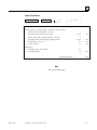
Contents
Chapter 1
Introduction..................................................................................................... 1-1
Chapter 2
System Operation ............................................................................................ 2-1
Section 1: Basic PLC Sweep Summary ......................................................... 2-2
Basic PLC Sweep ................................................................................................... 2-3
Housekeeping ......................................................................................................... 2-4
Input Scan .............................................................................................................. 2-4
Application Program Task Execution (Logic Window) ............................................ 2-5
Output Scan ........................................................................................................... 2-5
Programmer Communications Window ................................................................... 2-6
System Communications Window ........................................................................... 2-7
Background Window .............................................................................................. 2-7
Window Modes....................................................................................................... 2-7
Data Coherency in Communications Windows......................................................... 2-8
CPU Sweep in STOP Mode .................................................................................... 2-9
PLC Sweep Modes ............................................................................................... 2-10
Section 2: User Reference Data.....................................................................2-11
User References .................................................................................................... 2-11
User Reference Size and Default ........................................................................... 2-13
%G User References and CPU Memory Locations................................................. 2-14
Bulk Memory Access (BMA)................................................................................ 2-14
Genius Global Data .............................................................................................. 2-14
Transitions and Overrides
.......................................................................... 2-15
Retentiveness of Logic and Data ........................................................................... 2-15
Data Scope ........................................................................................................... 2-16
Data Types ........................................................................................................... 2-17
System Status References...................................................................................... 2-18
Fault References ................................................................................................... 2-21
Section 3: Program Organization .................................................................2-24
Ladder Logic Programming................................................................................... 2-25
Main Block........................................................................................................... 2-26
Blocks .................................................................................................................. 2-27
Examples of Using Blocks .................................................................................. 2-27
How Blocks Are Called....................................................................................... 2-30
Blocks and Local Data ................................................................................. 2-31
Parameterized Subroutine Blocks .......................................................................... 2-32
Parameterized Subroutine Blocks and Local Data.................................................. 2-32
How Parameterized Subroutine Blocks Are Called................................................. 2-33
Referencing Formal Parameters Within a Parameterized Subroutine Block............. 2-34
Restrictions on Formal Parameters within a Parameterized Subroutine Block......... 2-35
External Blocks .................................................................................................... 2-36
GFK-1192B
v
Contents
How External Blocks Are Called........................................................................... 2-36
External Blocks and Local Data ............................................................................ 2-37
Local Data Initialization........................................................................................ 2-37
Standalone C Programs......................................................................................... 2-38
Data Encapsulation............................................................................................... 2-38
Input/Output Specifications................................................................................. 2-39
Standalone C Programs and Local Data ................................................................ 2-41
Local Data Initialization ..................................................................................... 2-41
Referencing I/O Specification Data Within a Standalone C Program...................... 2-42
Data Coherency of I/O Specifications.................................................................. 2-42
Using LD vs. Standalone C Programs ................................................................... 2-43
Differences in Operation: LD and Standalone C Programs ..................................... 2-43
Retentiveness of Data.......................................................................................... 2-43
Global Data ........................................................................................................ 2-44
Interrupt Execution............................................................................................. 2-44
Queuing of Interrupts.......................................................................................... 2-44
System Status References.................................................................................... 2-44
Section 4: PLC Sweep Modes and Program Scheduling Modes.................2-45
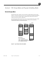
Normal Sweep Mode ............................................................................................ 2-45
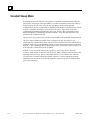
Constant Sweep Mode .......................................................................................... 2-46
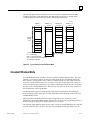
Constant Window Mode........................................................................................ 2-47
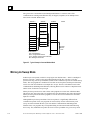
Microcycle Sweep Mode....................................................................................... 2-48
Program Scheduling Modes................................................................................... 2-51
Choosing PLC Sweep and Program Scheduling Modes .......................................... 2-52
User Program Execution ....................................................................................... 2-52
User Program Priorities ...................................................................................... 2-52
User Program Execution in Normal Sweep, Constant Sweep, and Constant Window
Modes................................................................................................................. 2-53
User Program Execution in Microcycle Sweep Mode............................................. 2-56
Global Data in Microcycle Sweep Mode....................................................... 2-59
Interrupt Handling ................................................................................................ 2-60
Interrupt Handling and Scheduling with Blocks ..................................................... 2-60
I/O Interrupt Blocks.............................................................................................. 2-61
Timed Interrupt Blocks ......................................................................................... 2-62
Parameters: .................................................................................................. 2-62
Valid Memory Types: .................................................................................. 2-63
Interrupt Handling and Scheduling with User Programs ......................................... 2-63
I/O-Triggered Programs........................................................................................ 2-63
Timed Programs ................................................................................................... 2-64
Interrupt Blocks vs. Interrupt Programs................................................................. 2-65
Interrupt Block............................................................................................. 2-65
Interrupt Program ........................................................................................ 2-65
Section 5: Run/Stop Operations ..................................................................2-66
Modes of Operation .............................................................................................. 2-66
vi
Series 90™-70 System Manual for Control Software Users–November 1999
GFK-1192B
Contents
Mode Transitions.................................................................................................. 2-67
Stop-to-Run Transition ......................................................................................... 2-67
Run-to-Stop Transition ......................................................................................... 2-67
Wind-Down Period for Microcycle Sweep Mode ................................................. 2-67
Section 6: Power-Up and Power-Down Sequences ......................................2-68
Power-Up ............................................................................................................. 2-68
Power-Up Self-Test .............................................................................................. 2-68
PLC Memory Validation....................................................................................... 2-68
System Configuration ........................................................................................... 2-69
Option Module Self-Test Completion .................................................................... 2-69
Option Module Dual Port Interface Tests .............................................................. 2-69
I/O System Initialization ....................................................................................... 2-70
Power-Down Sequence ......................................................................................... 2-70
Retention of Data Memory Across Power Failure.................................................. 2-71
Section 7: Clocks and Timers........................................................................2-72
Elapsed Time Clock.............................................................................................. 2-72
Time-of-Day Clock ............................................................................................... 2-72
Watchdog Timer ................................................................................................... 2-73
Software Watchdog Timer .................................................................................... 2-73
Hardware Watchdog Timer ................................................................................... 2-73
Section 8: System Security ............................................................................2-74
Passwords and Privilege Levels............................................................................. 2-74
Protection Level Request from Programmer........................................................... 2-75
Disabling Passwords............................................................................................. 2-76
OEM Protection.................................................................................................... 2-76
Write Protect Keyswitch ....................................................................................... 2-76
Section 9: Series 90-70 PLC I/O System .......................................................2-77
I/O Data Mapping ................................................................................................ 2-78
Default Conditions................................................................................................ 2-78
Genius I/O............................................................................................................ 2-78
Genius I/O Bus Configuration............................................................................... 2-78
Genius I/O Data Mapping..................................................................................... 2-78
Analog Grouped Block.......................................................................................... 2-79
Low-Level Analog Blocks ..................................................................................... 2-79
Default Conditions................................................................................................ 2-79
Genius Global Data Communications.................................................................... 2-80
FIP I/O................................................................................................................. 2-80
GFK-1192B
Contents
vii
Contents
FIP I/O Bus Configuration.................................................................................... 2-80
90-30 FIP Remote I/O Scanner ..................................................................... 2-80
FIP Bus Interface Unit (Field Control) ......................................................... 2-80
Generic FIP I/O ........................................................................................... 2-81
FIP I/O Fault Data ....................................................................................... 2-81
FIP I/O Data Mapping.......................................................................................... 2-81
Default Conditions................................................................................................ 2-81
Diagnostic Data Collection.................................................................................... 2-81
Discrete I/O Diagnostic Information...................................................................... 2-82
Analog I/O Diagnostic Data .................................................................................. 2-82
Chapter 3
Fault Explanation and Correction.................................................................. 3-1
Section 1: System Faults ................................................................................ 3-2
System Fault References ......................................................................................... 3-3
Configurable Fault Actions ..................................................................................... 3-4
Non-Configurable Faults ......................................................................................... 3-6
Fault Contacts ........................................................................................................ 3-7
Fault Locating References (Rack, Slot, Bus, Module).............................................. 3-7
Format of Fault References ..................................................................................... 3-7
Behavior of Fault References .................................................................................. 3-8
Alarm Contacts....................................................................................................... 3-8
Point Faults ............................................................................................................ 3-9
Section 2: Fault Handling .............................................................................3-10
Alarm Processor ................................................................................................... 3-10
Classes of Faults................................................................................................... 3-11
System Reaction to Faults..................................................................................... 3-11
Fault Tables ......................................................................................................... 3-11
Fault Action.......................................................................................................... 3-12
Fault Response ..................................................................................................... 3-12
PLC Fault Table................................................................................................... 3-13
I/O Fault Table..................................................................................................... 3-14
User-Defined Faults .............................................................................................. 3-15
Accessing Additional Fault Information................................................................. 3-16
Section 3: PLC Fault Table Explanations ....................................................3-17
Configurable Faults .............................................................................................. 3-18
Loss of or Missing Rack ....................................................................................... 3-18
Loss of or Missing Option Module........................................................................ 3-19
Addition of or Extra Rack..................................................................................... 3-21
Reset of, Addition of, or Extra Option Module ...................................................... 3-21
System Configuration Mismatch ........................................................................... 3-22
System Bus Error ................................................................................................. 3-25
viii
Series 90™-70 System Manual for Control Software Users–November 1999
GFK-1192B
Contents
PLC CPU Hardware Failure ................................................................................. 3-26
Module Hardware Failure ..................................................................................... 3-26
Option Module Software Failure ........................................................................... 3-27
Program or Block Checksum Failure..................................................................... 3-28
Low Battery Signal............................................................................................... 3-28
Constant Sweep or Microcycle Time Exceeded...................................................... 3-29
PLC System Fault Table Full................................................................................ 3-29
I/O Fault Table Full.............................................................................................. 3-29
Application Fault .................................................................................................. 3-30
Non-Configurable Faults ....................................................................................... 3-31
System Bus Failure............................................................................................... 3-32
No User Program on Power-Up ............................................................................. 3-32
Corrupted User Program on Power-Up .................................................................. 3-33
Window Completion Failure.................................................................................. 3-34
Password Access Failure....................................................................................... 3-34
Null System Configuration for Run Mode ............................................................. 3-34
PLC CPU System Software Failure....................................................................... 3-35
Too Many Bus Controllers.................................................................................... 3-36
Communications Failure During Store................................................................... 3-36
Run Mode Store Failure........................................................................................ 3-37
Section 4: I/O Fault Table Explanations ......................................................3-38
Circuit Fault ......................................................................................................... 3-41
Discrete Fault ....................................................................................................... 3-42
Analog Fault......................................................................................................... 3-43
Low-Level Analog Fault ....................................................................................... 3-44
GENA Fault ......................................................................................................... 3-45
Loss of IOC (I/O Controller)................................................................................. 3-45
Addition of IOC (I/O Controller)........................................................................... 3-45
Loss of I/O Module............................................................................................... 3-46
Addition of I/O Module......................................................................................... 3-46
Extra I/O Module ................................................................................................. 3-46
Loss of Block ....................................................................................................... 3-47
Addition of Block.................................................................................................. 3-47
Extra Block .......................................................................................................... 3-47
I/O Bus Fault........................................................................................................ 3-48
Module Fault ........................................................................................................ 3-49
IOC (I/O Controller) Software Fault ..................................................................... 3-49
IOC (I/O Controller) Hardware Failure ................................................................. 3-50
Forced and Unforced Circuit ................................................................................. 3-50
Block Switch ........................................................................................................ 3-50
GFK-1192B
Contents
ix
Contents
Appendix A
CPU Performance Data...................................................................................A-1
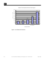
Ethernet Global Data Sweep Impact..................................................................... A-23
Relative CPU Performance Comparison ............................................................... A-37
Test Program ..................................................................................................... A-37
Interpreting the Chart ................................................................................. A-37
x
Appendix B
Interpreting Faults ..........................................................................................B-1
Appendix C
Memory Allocation..........................................................................................C-1
Appendix D
Using Floating-Point Numbers .......................................................................D-1
Series 90™-70 System Manual for Control Software Users–November 1999
GFK-1192B
Chapter
Introduction
1
The Series 90™-70 PLC is a member of the GE Fanuc Series 90 PLC family of programmable
logic controllers (PLCs). It is easy to install and configure, offers advanced programming
features, and is designed for compatibility with other PLCs offered in the Series 90 family of
PLCs. Through the use of the latest design and manufacturing technology, open architecture
VME bus, and the ability to connect to Genius and FIP I/O and several CPU models, the Series
90-70 PLC provides a powerful, cost-effective platform for small applications through the very
largest.
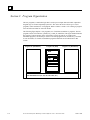
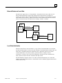
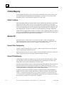
Software Architecture
The programming software architecture provides a platform upon which to build structured
control programs. Programs may be built from many program blocks, each of which is related to
a control function. Structured programs permit parallel development of a complete program as a
collection of program blocks developed independently by many different individuals or OEMs.
Structured programs are also easier to understand and debug. A control program may be built of
many smaller program blocks, each of which can relate to a specific machine function. This
approach makes it easier to isolate and associate control logic with machine functions.
The programming language and representation are based on IEC working draft 65A standard.
Eventual adoption of this standard will make it easier to create programs that can be understood
globally. It establishes the Series 90-70 PLC in the vanguard of the movement toward recognized
international standards.
Beginning with Release 6 PLC CPUs, it has been possible to incorporate multiple programs into a
folder. All of these programs can be written in C or one program can be an RLD or SFC program
with the remaining programs written in C. In addition, Release 6, and later CPUs have built-in
debugging capabilities for C programs and external blocks. For more information on this feature,
refer to the C Programmer’s Toolkit manual (GFK-0646C or later).
Terminology Used in This Manual
The following terms are used with their defined meanings throughout this manual:
User program: any user-generated code, that is, an RLD program, an SFC program, or a
standalone C program
Block: any RLD block, Parameterized Subroutine Block, or external block—an external
block being either a C block or an C function block (CFBK)
GFK-1192B
1-1
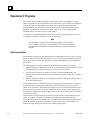
1
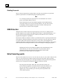
Fault Handling
Faults are handled by a software alarm processor function which time-stamps and logs I/O and
system faults in two tables (the PLC fault table and the I/O fault table). These tables can be
displayed on the programming software screen or uploaded to a host computer or other
coprocessor. Application programs can also gain access to the fault information.
Hardware Configuration
Configuration is the process of assigning physical locations, logical addresses, and parameter
values to the hardware modules in the system. It may be done either before or after programming;
however, it is recommended that configuration be done first.
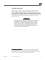
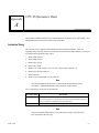
Using This Manual
This manual is distributed with Control programming software, and describes the PLC hardware
and programming features available in the CPU. Refer to the current IPI distributed with Control
for CPU and programming features not described in this version of the manual.
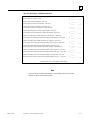
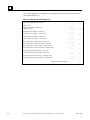
Reference information is available in this manual, as described below:
Appendix A, CPU Performance Data, lists the memory size in bytes and the execution time in
microseconds for each of the programming instructions. Appendix A also contains timing
information for other PC tasks which, when used in conjunction with the instruction timings, can
be used to predict CPU sweep times.
Appendix B, Interpreting Faults, describes how to interpret the message structure format when
reading the PLC and I/O fault tables.
Use the worksheet in Appendix C, Memory Allocation, to determine the total number of bytes of
user data used and how much is still available for the user program.
Refer to Appendix D, Using Floating-Point Numbers, for IEEE formats when dealing with
floating-point math operations.
Revisions to This Manual
Appropriate changes have been made to this manual to reflect feature changes, corrections, and
updates to existing information. The changes are:
Name of manual changed to reflect that this reference manual is for Control software
users
References made to CPX and CGR model CPUs, where appropriate, throughout the
manual
Bulk Memory Access information added (chapter 2)
Value for Constant Sweep timer corrected (chapter 2, pg. 2-46)
Note added after Table 2-18 regarding CPU Mode switch and description of privilege
level 1 updated in table
Description of System Faults updated (chapter 3, pg. 3-2)
Appendix A, CPU Performance Data, tables revised (all information not available, will
be added to a future version)
Paragraph added , beginning with “Each Ethernet Global . . . . “, page A-23
Section titled “Relative CPU Test Performance” added at end of Appendix A
1-2
Series 90™-70 System Manual for Control Software Users – November 1999
GFK-1192B
Chapter
2
System Operation
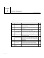
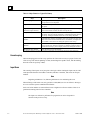
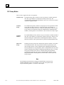
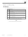
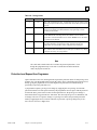
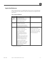
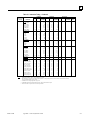
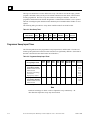
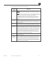
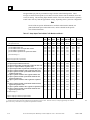
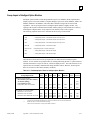
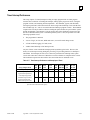
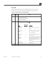
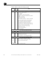
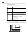
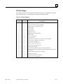
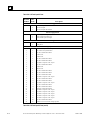
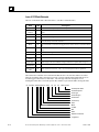
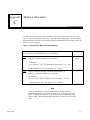
This chapter describes certain system operations of the Series 90-70 PLC system. The table
displayed below summarizes the content of each section in this chapter.
Section
GFK-1192B
Title
Description
Page
1
Basic PLC Sweep
Summary
Describes the major steps in a typical PLC sweep, including
application program task execution, Programmer
Communications Window, System Communications Window,
and Background Window.
2-2
2
User Reference Data
Describes user reference data, system status/fault references,
and data types.
2-11
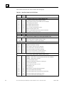
3
Program Organization
Describes the structure and use of LD blocks, PSB blocks,
external blocks, and standalone C programs.
2-24
4
PLC Sweep Modes and
Program Scheduling
Modes
Explains Normal Sweep, Constant Sweep, Constant Window,
Microcycle Sweep, and Stop modes. Also describes Triggered
Interrupt blocks/programs and timed interrupts.
2-45
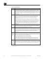
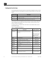
5
Run/Stop Operations
Describes the four modes of operation supported by the 90-70
PLC: Run/Outputs Enabled, Run/Outputs Disabled, Stop/IO
Scan, and Stop/No IO Scan.
2-66
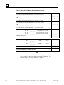
6
Power-Up and
Describes the three parts of system power-up (including
Power-Down Sequences power-up self-test, PLC operation initialization, and system
configuration), the power-down sequence, and the retention
of data memory.
2-68
7
Clocks and Timers
Describes the elapsed time clock, time-of-day clock, and
watchdog timers.
2-72
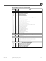
8
System Security
Describes protection level request from the programmer,
including password assignment and block lock, OEM
protection and password, and the write protect keyswitch.
2-74
9
Series 90-70 PLC I/O
System
Describes I/O data mapping and diagnostic data.
2-77
2-1
2
Section 1: Basic PLC Sweep Summary
The user program(s) in the Series 90-70 PLC execute in a repetitive fashion until stopped by a
command from the programmer or a command from another device. In addition to executing the
user program(s), the PLC obtains data from input devices, sends data to output devices, performs
internal housekeeping, services the programmer, services other communications, and performs
self-tests. The sequence of operations necessary to execute these components one time is called a
sweep. This section summarizes the sweep phases; for more detailed information, refer to section
4 of this chapter.
2-2
Series 90™-70 System Manual for Control Software Users – November 1999
GFK-1192B
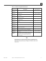
2
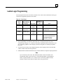
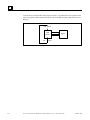
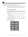
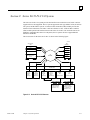
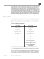
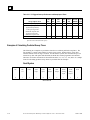
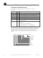
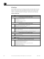
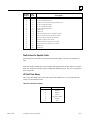
Basic PLC Sweep
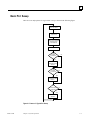
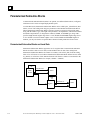
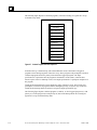
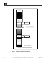
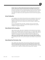
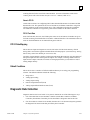
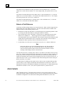
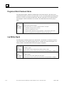
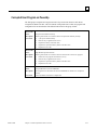
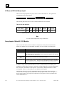
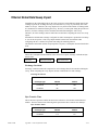
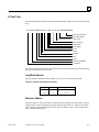
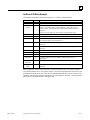
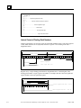
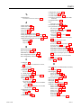
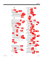
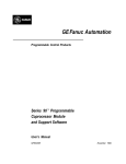
There are seven major phases in a typical PLC sweep as shown in the following figure:
HOUSEKEEPING
START-OF-SWEEP
INPUT SCAN
APPLICATION PROGRAM
TASK EXECUTION
(LOGICWINDOW)
OUTPUT SCAN
PROG
WINDOW
SCHEDULED
?
NO
YES
PROGRAMMER
COMMUNICATIONS
WINDOW
COMM
WINDOW
SCHEDULED
?
NO
YES
SYSTEM
COMMUNICATIONS
WINDOW
BACKGROUND
TASK
SCHEDULED
?
NO
YES
BACKGROUND
WINDOW
START NEXT SWEEP
Figure 2-1. Phases of a Typical PLC Sweep
GFK-1192B
Chapter 2 System Operation
2-3
2
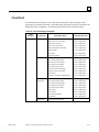
Table 2-1. Major Phases in a Typical PLC Sweep
Step
Description
Housekeeping
Updating %S bits, determining timer update values, and determining the
sweep mode occur in this phase.
Input Scan
The CPU reads input data from Bus controllers and input modules during
this phase.
Application Program Task
Execution (Logic Window)
The CPU solves the logic program(s), using data obtained from the input
devices and sets bits to affect the state of output devices.
Output Scan
The CPU writes output data to Bus controllers and output modules during
this phase. The user program checksum is computed during this phase of
the sweep. Polling for faulted boards also occurs during this phase.
Programmer Communications
Window
Communication with the programmer when using serial occurs here with
data and/or status transfer in both directions. In addition, reconfiguration
of a module or rack also occurs during this portion of the sweep.
System Communications
Window
Communications with all intelligent devices except the programmer when
using a serial occur during this window. For example, supplying data to a
PCM* that is driving a process display would occur during this window.
Background Task Window
CPU self-tests occur in this window.
*For information about the PCM, refer to the Series 90™ Programmable Coprocessor Module and Software Support (GFK-0255).
Housekeeping
The housekeeping portion of the sweep performs all of the tasks necessary to prepare for the start
of the sweep. This includes updating %S bits, determining timer update values, and determining
the mode of the sweep (Stop or Run).
Input Scan
The scanning of the inputs occurs just prior to the logic solution. During the input scan, the CPU
reads input data from the Genius Bus Controllers, FIP Bus Controllers, and Series 90-70 input
modules.
Note
Beginning with Release 7.0, Ethernet global data is also read during this scan.
When referring to FIP in this scan, only periodic VCOM (MPS) services are affected. Messages
are received in the System Communication Window.
Series 90-70 I/O modules are scanned from lowest to highest I/O reference address. There is no
guaranteed scanning order for Bus Controllers.
Note
The input scan will not be performed if a program has an active Suspend I/O
function on the previous sweep.
2-4
Series 90™-70 System Manual for Control Software Users – November 1999
GFK-1192B
2
Application Program Task Execution (Logic Window)
The Logic Window is the phase of the sweep where user programs execute. Immediately following
the completion of the input scan, the PLC Executive determines which user program(s) are to be
run. Programs are then resumed and/or invoked as necessary. Solving the logic provides a new set
of outputs.
Interrupt programs and blocks can execute during any phase of the sweep. Refer to section 4 for
further details.
There are many ways in which program execution can be controlled to meet the system’s timing
requirements. The following is a partial list of the commonly used methods:
•
•
•
•
•
Mask Compare and JUMP functions can be used to skip portions of the logic.
The Suspend I/O function can be used to stop both the input scan and output scan for one
sweep. I/O can be updated, as necessary, during the logic execution through the use of DO
I/O instructions.
The Service Request function can be used to suspend or change the time allotted to the
window portions of the sweep.
Program logic can be structured so that blocks and programs are called more or less
frequently, depending on their importance and on timing constraints.
Microcycle sweep mode can be used to phase programs, which need to run less often while
limiting the logic window execution time.
A list of execution times for instructions can be found in Appendix A.
Note
In Microcycle Sweep mode, the Logic Window can be skipped or preempted as
necessary by the PLC Executive.
Output Scan
Outputs are scanned immediately following logic solution. During the output scan, the CPU sends
output data to the Genius Bus Controllers, FIP Bus Controllers, and Series 90-70 output modules.
Beginning with Release 7.0, Ethernet global data is also produced in this phase.
Series 90-70 output modules are scanned from lowest to highest I/O reference address. Bus
Controllers are scanned from rack 0 to rack 7 and lowest to highest slot number within each rack.
Note
The output scan will not be performed if a program has an active Suspend I/O
function on the current sweep.
When referring to FIP in this scan, only periodic VCOM (MPS) services are
affected. Messages are received in the System Communication Window.
GFK-1192B
Chapter 2 System Operation
2-5
2
Polling for faulted boards also occurs during the output scan phase of the sweep. Faulted board
polling recognizes replacement boards for faulted ones and reconfigures them into the system. If a
board that was previously in the system or configured by the user to be in the system is listed as
faulted, it must be polled periodically to determine if a new board has replaced it. Once a
previously faulted board is detected as no longer faulted, reconfiguration is run in the Programmer
Communications Window until the board(s) are reconfigured into the system.
The background checksum calculation also occurs during the output phase of the sweep. During
each output scan phase of the sweep, the configured amount of words of user program is included
in the checksum calculation. This checksum helps to ensure the integrity of the user logic while
the CPU is executing. If the CPU is configured to perform a background checksum calculation (16
is the default), then this part of the output phase is performed; otherwise, it is skipped.
There are other tests performed during the Output Scan: Processor test checks basic operation of
the microprocessor and BCP Opcode test checks basic operation of all BCP instructions.
Note
Beginning with the Release 7 CPUs, for Microcycle Sweep only, the background
checksum calculation will occur during the input phase of the sweep.
Programmer Communications Window
This part of the sweep is dedicated to communicating with the programmer and performing
faulted board reconfiguration. This is also when communication with the C debugger occurs. If
there is a programmer attached, a debugging session is active, or if there is a board in the system
that requires reconfiguration (as detected during the faulted board polling portion of the sweep),
the CPU executes the Programmer Window. The Programmer Window will not execute if there is
no programmer attached, no active debug session occurring, and no board to be configured in the
system. During the Programmer Window, highest priority is given to board configuration. Boards
are configured as needed, up to the total time allocated to the Programmer Window.
The Programmer Window is used for communication between the CPU and the two dedicated
programmer ports: the built-in SNP connection and the parallel programmer connection. The
CPU will complete any previously unfinished requests and then begin to process any pending
requests in the queue. When the time allocated for the window expires, processing stops.
The Programmer Window time defaults to 10 milliseconds. This value can be configured and
stored to the PLC or it can be changed online using your programming software.
Time and execution of the Programmer Window can also be dynamically controlled from the user
program using Service Request function #3. The Programmer Communications Window time can
be set to a value from 0 to 255 milliseconds.
Note
Even if the Programmer Window is skipped, the PLC can still respond to
commands to change mode or state, or to redefine the Programmer Window if
the programmer is attached through the parallel port on the Bus Transmitter
Module (BTM), or by manually putting the PLC into stop mode.
2-6
Series 90™-70 System Manual for Control Software Users – November 1999
GFK-1192B
2
System Communications Window
The System Communications Window is the part of the sweep used for communication between
the CPU and intelligent modules such as the PCM, Genius Bus Controller, FIP Bus Controller,
and TCP/IP Ethernet modules.
At the start of the System Communications Window, the CPU will complete any previously
unfinished request before executing any pending requests in the queue. When the time allocated
for the window expires, processing stops.
The System Communications Window defaults to “Run to Completion” mode. This means that all
currently pending requests on all intelligent option modules are processed every sweep. A
different mode can be configured and stored to the PLC, or it can be changed online using your
programming software.
Time and execution of the System Communications Window can also be dynamically controlled
from the user program using Service Request function #4. This allows communications functions
to be skipped during certain time-critical sweeps. The System Communications Window time can
be set to a value from 0 to 255 milliseconds.
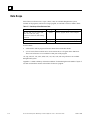
Background Window
A CPU self-test is performed in this window. Included in this self-test is a verification of the
checksum for the 90-70 CPU operating system software.
The Background Window time defaults to 0 milliseconds. A different value can be configured and
stored to the PLC, or it can be changed online using your programming software.
Time and execution of the Background Window can also be dynamically controlled from the user
program using Service Request function #5. This allows background functions to be skipped
during certain time-critical sweeps.
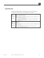
Window Modes
The previous sections have described the phases of a typical PLC sweep. The Programmer
Window, System Communications Window, and Background Window phases of the PLC sweep
can be run in various modes, based on the PLC Sweep mode. (PLC sweep modes are described in
detail in section 4.) The following three window modes are available:
GFK-1192B
Run-toCompletion
In Run-to-Completion mode, all requests made when the window has started
are serviced. When all pending requests in the given window have completed,
the PLC will transition to the next phase of the sweep.
Constant
In Constant Window mode, the total amount of time that the Programmer
Communications Window and Background Window run is fixed. If the time
expires while in the middle of servicing a request, these windows are closed,
and communications will be resumed the next sweep. If no requests are
pending in this window, the PLC will cycle through these windows the
specified amount of time polling for further requests. If any window is put in
constant window mode, all will be in constant window mode.
Chapter 2 System Operation
2-7
2
Limited
In Limited mode, the maximum time that the window runs is fixed. If time
expires while in the middle of servicing a request, the window is closed, and
communications will be resumed the next time that the given window is run.
If no requests are pending in this window, the PLC will proceed to the next
phase of the sweep.
Data Coherency in Communications Windows
When running in Constant or Limited Window mode, the Programmer and System
Communications Windows may be terminated early in all PLC sweep modes. If an external
device, such as a GBC (Genius Bus Controller), is transferring a block of data, the coherency of
the data block may be disrupted if the communications window is terminated prior to completing
the request. The request will complete during the next sweep; however, part of the data will have
resulted from one sweep and the remainder will be from the following sweep. When the PLC is in
Normal Sweep mode and the Communications Window is in Run-to-Completion mode, the data
coherency problem described above does not exist.
2-8
Series 90™-70 System Manual for Control Software Users – November 1999
GFK-1192B
2
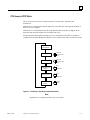
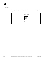
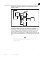
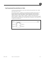
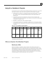
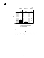
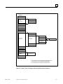
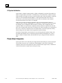
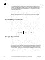
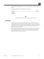
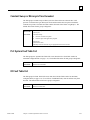
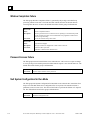
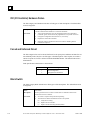
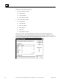
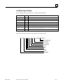
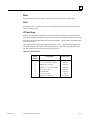
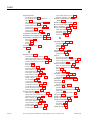
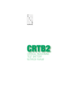
CPU Sweep in STOP Mode
The 90-70 PLC has two modes of operation while it is in Stop mode: Stop/NoIO and
Stop/IOScan.
When the PLC is in Stop/NoIO mode the Input Scan, Logic Window, and Output Scan phases of
the PLC sweep are skipped.
When the PLC is in Stop/IOScan mode the Logic Window phase of the PLC is skipped but the
Input Scan and Output Scan phases are performed each sweep.
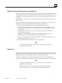
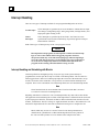
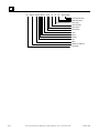
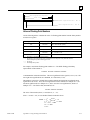
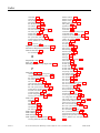
In both Stop/NoIO and Stop/IOScan modes, the two Communications Windows run in Run-toCompletion mode and the Background Window runs in Limited mode with a 10 millisecond limit.
START-OF-SWEEP
HOUSEKEEPING
EXECUTES
INPUT SCAN
IN STOP/IOSCAN
ONLY
OUTPUT SCAN
EXECUTES
IN STOP/IOSCAN
ONLY
PROGRAMMER
COMMUNICATIONS
WINDOW
SYSTEM
COMMUNICATIONS
WINDOW
BACKGROUND
WINDOW
RUNS
TO
COMPLETION
RUNS
TO
COMPLETION
LIMITED
(10 MS)
Figure 2-2. CPU Sweep in Stop/NoIO and Stop/IOScan Mode
Note
Stop/IOScan is not supported in Microcycle Sweep mode.
GFK-1192B
Chapter 2 System Operation
2-9
2
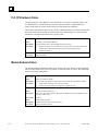
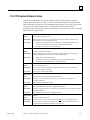
PLC Sweep Modes
The 90-70 PLC supports four PLC sweep modes:
Normal Sweep
In Normal Sweep mode, each PLC sweep can consume a variable amount of
time. The Logic Window is executed in its entirety each sweep. The
Communications and Background Windows can be set to execute in a Limited
or Run-to-Completion mode.
Constant
Sweep
In Constant Sweep mode, each PLC sweep begins at a user-specified Constant
Sweep time after the previous PLC sweep began. The Logic Window is
executed in its entirety each sweep. If there is sufficient time at the end of the
sweep, the PLC will alternate among the Communications and Background
Windows, allowing them to execute until it is time for the next sweep to begin.
Constant
Window
In Constant Window mode, each PLC sweep can consume a variable amount of
time. The Logic Window is executed in its entirety each sweep. The PLC will
alternate among the Communications and Background Windows, allowing
them to execute for a time equal to the user-specified Constant Window timer.
Microcycle
Sweep
In Microcycle Sweep mode, like Constant Sweep mode, each PLC sweep takes
a fixed amount of time. The user specifies the total sweep time (base cycle
time) and the total time for the Communications and Background Windows.
The Logic Window can be preempted in order to maintain the total sweep time
and the Communications Windows and Background Window times. To satisfy
the specified window times, the PLC alternates among the Programmer
Communications Window, the System Communications Window, and the
Background Window, allowing them to execute until it is time for the next
sweep to begin.
Note
The information presented above summarizes the different sweep modes. For
detailed information on PLC Sweep Modes, refer to “PLC Sweep Modes and
Program Scheduling Modes” in section 4 of this chapter.
2-10
Series 90™-70 System Manual for Control Software Users – November 1999
GFK-1192B
2
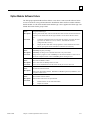
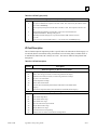
Section 2: User Reference Data
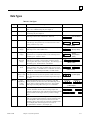
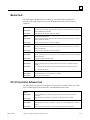
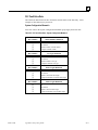
User References
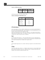
The PLC data used in an application program is stored as either discrete or register references.
Table 2-2. Register References
Type
Description
%R
Use the prefix %R to assign system register references, which will store program data such as
the results of calculations.
%AI
The prefix %AI represents an analog input register. This prefix is followed by the register
address of the reference (for example, %AI0015). An analog input register holds the value of
one analog input or another value.
%AQ
The prefix %AQ represents an analog output register. This prefix is followed by the register
address of the reference (for example, %AQ0056). An analog output register holds the value of
one analog output or another value.
%P*
Use the prefix %P to assign program register references that will store program data from the
_MAIN block. This data can be accessed from all program blocks. The size of the %P data
block is based on the highest %P reference in all blocks. (For more information, refer to the
Appendix C, “Memory Allocation.”)
%L*
Use the prefix %L to assign local register references that will store program data unique to a
block. The size of the %L data block is based on the highest %L reference in the associated
block. (For more information, refer to Appendix C, “Memory Allocation.”)
* These reference types are scoped at a program level and are therefore only visible to LD programs.
Note
All register references are retained across a power cycle to the CPU.
GFK-1192B
Chapter 2 System Operation
2-11
2
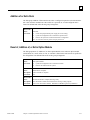
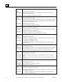
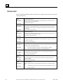
Table 2-3. Discrete References
Type
Description
%I
The %I prefix represents input references. This prefix is followed by the reference’s address in
the input table (for example, %I00121). %I references are located in the input status table,
which stores the state of all inputs received from input modules during the last input scan. A
reference address is assigned to discrete input modules using your programming software. Until
a reference address is assigned, no data will be received from the module. %I memory is
always retentive.
%Q
The %Q prefix represents physical output references. The coil check function checks for
multiple uses of %Q references with relay coils or outputs on functions. Beginning with
Release 4 of the software, you can select the level of coil checking desired (Single, Warn
Multiple, or Multiple). Refer to “Rung Acceptance” in the online help for additional
information.
The %Q prefix is followed by the reference’s address in the output table (for example,
%Q00016). %Q references are located in the output status table, which stores the state of the
output references as last set by the application program. This output status table’s values are
sent to output modules at the end of the program scan. A reference address is assigned to
discrete output modules using your programming software. Until a reference address is
assigned, no data is sent to the module. A particular %Q reference may be either retentive or
non-retentive. *
%M
The %M prefix represents internal references. The coil check function of your programming
software checks for multiple uses of %M references with relay coils or outputs on functions. A
particular %M reference may be either retentive or non-retentive. *
The %T prefix represents temporary references. These references are never checked for
multiple coil use and can, therefore, be used many times in the same program even when coil
use checking is enabled. %T may be used to prevent coil use conflicts while using the cut/paste
and file write/include functions. Because this memory is intended for temporary use, it is never
retained through power loss or Run-to-Stop-to-Run transitions and cannot be used with
retentive coils.
The %S, %SA, %SB, and %SC prefixes represent system status references. These references
are used to access special PLC data such as timers, scan information, and fault information. For
example, the %SC0012 bit can be used to check the status of the PLC fault table. Once the bit
is set on by an error, it will not be reset until after the sweep.
•
%S, %SA, %SB, and %SC can be used on any contacts.
•
%SA, %SB, and %SC can be used on retentive coils -(M)-.
•
%S can be used as word or bit-string input arguments to functions or function blocks.
• %SA, %SB, and %SC can be used as word or bit-string input or output arguments to
functions and function blocks. %S, %SA, %SB, and %SC references are non-retentive.
The %G, %GA, %GB, %GC, %GD, and %GE prefixes represent global data references. These
references are used to access data shared among several PLCs. %G, %GA, %GB, %GC, %GD,
and %GE references can be used on contacts and retentive coils because the memory is always
retentive. %G, %GA, %GB, %GC, %GD, and %GE cannot be used on non-retentive coils.
%T
%S
%SA
%SB
%SC
%G
%GA
%GB
%GC
%GD
%GE
* Retentiveness is based on the type of coil. For more information, refer to “Retentiveness of Logic and Data”
later in this section.
2-12
Series 90™-70 System Manual for Control Software Users – November 1999
GFK-1192B
2
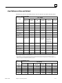
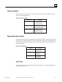
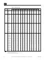
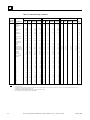
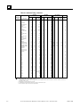
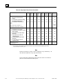
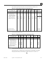
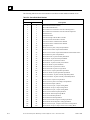
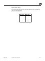
User Reference Size and Default
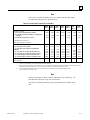
Maximum user references and default reference sizes for each CPU are listed in the tables below.
Table 2-4. User Reference Sizes
CPU Model
Item
935/928
925/915/79
0
924/914
788
780/781
782/789
771/772
731/732
Maximum %I
reference
12288 points
12288 points
352 points1
12288 points2
2048 points2
512 points2
Maximum %Q
reference
12288 points
12288 points
352 points1
12288 points2
2048 points2
512 points2
Maximum %M
reference
12288 points
12288 points
12288 points
12288 points
4096 points
2048 points
Maximum %T
reference
256 points
256 points
256 points
256 points
256 points
256 points
%S total
(S, SA, SB, SC)
512 points
512 points
512 points
512 points
512 points
512 points
%G (GA, GB, GC,
GD, GE)
7680 points
7680 points
7680 points
7680 points
7680 points
1280 points
User RAM
1024K bytes
(6MB for 928)
512K bytes
512K bytes
512K bytes
(CPX 782 has
1024 KB)
CPU771/2:
64, 128, 256, 512
KB depending on
expansion memory
board purchased
CPX772: 512 KB
32K bytes
Maximum %AI
reference
8K words
8K words
8K words
8K words
8K words
8K words
Maximum %AQ
reference
8K words
8K words
8K words
8K words
8K words
8K words
Maximum %R, 1K
word increments
16K words
16K words
16K words
16K words
16K words
16K words
Maximum %L (per
block)
8K words.
8K words
8K words
8K words
8K words
8K words
Maximum %P
8K words
8K words
8K words
8K words
8K words
8K words
1
Total number of physical input and output points together cannot exceed 352 points. This corresponds to approximately 100 redundant points.
Refer to Chapter 1 of GFK-1277 for more information.
2
Prior to Release 6 of Logicmaster, the programming software restricted the total %I and %Q to the limit shown individually for each. For
example, when using previous programming packages with a 782 CPU, there was a maximum of 12288 points of %1 and %Q combined. This
restriction no longer exists with the newer versions of Logicmaster.
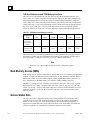
Table 2-5. Default Memory Sizes
CPU Model
Memory
Type
%AI
%AQ
GFK-1192B
935/928
925/915/790
64 words
924/914
64 words
780/781/782
788/789
64 words
781/782
64 words
771/772
64 words
731/732
64 words
64 words
64 words
64 words
64 words
64 words
64 words
%R
1024 words
1024 words
1024 words
1024 words
1024 words
1024 words
%P
0 words
0 words
0 words
0 words
0 words
0 words
%L
0 words
0 words
0 words
0 words
0 words
0 words
Chapter 2 System Operation
2-13
2
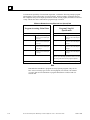
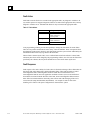
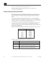
%G User References and CPU Memory Locations
The Series 90-70 CPU contains only one data space for all of the global data references (%G,
%GA, %GB, %GC, %GD, and %GE). The internal CPU memory for this data is 7680 bits long.
Your programming software provides the user with a subdivided representation by using %G,
%GA, %GB, %GC, %GD, and %GE prefixes; allowing each of these prefixes to be used with bit
offsets in the range 1-1280. Your programming software interprets the requested global reference
type (%G, %GA, %GB, %GC, %GD, or %GE) and converts it to the %G memory type and
correct bit offset for use by the CPU. The actual mapping is shown in the table displayed below.
Table 2-6. %G References and Memory Locations
Global Data
Type
References
Used by the
Programming
Software
Memory
Locations Used
by the CPU
%G
%G1–1280
%G1–1280
%GA
%GB
%GC
%GD
%GE
%GA1–1280 %GB1–1280 %GC1–1280 %GD1–1280 %GE1–1280
%G1281–
2560
%G2561–
3840
%G3841–
5120
%G5121–
6400
%G6401–
7680
This information is useful when programming 90-70 CPU applications in C language using the C
Programmer’s Toolkit. For more information about using the C Programmer’s Toolkit, refer to
the C Programmer’s Toolkit for Series 90™ PLCs User’s Manual (GFK-0646).
Note
A model 731 CPU supports only %G since it has only 1280 points of global
data.
Bulk Memory Access (BMA)
Bulk Memory Access provides a large block of memory that can be accessed from your application
program. Possible uses include recipe files, bulk storage, memory allocation, temporary memory
blocks, and so forth. Use of this feature requires Control programming software version 2.2, or
later. On-line help for the BMA feature are available in Control software version 2.3.
The BMA is a contiguous block of memory (up to 4 Mbytes) that can be used by logic programs
and external devices. BMA is available in the CPX CPUs (CPX772, 782, 928, 935) with CPU
release 7.80, or later. A service request (SVCREQ #36) is used to read from the BMA to a local
buffer area in the PLC, write from the local buffer to the PLC, and retrieve the address of the
BMA in the PLC.
Genius Global Data
The Series 90-70 PLC supports the sharing of data among multiple PLC systems that share a
common Genius I/O bus. This mechanism provides a means for the automatic and repeated
transfer of %G, %I, %Q, %AI, %AQ, and %R data. No special application programming is
required to use global data since it is integrated into the I/O scan. All GE Fanuc PLCs that have
Genius I/O capability can send and receive global data from a Series 90-70 PLC.
2-14
Series 90™-70 System Manual for Control Software Users – November 1999
GFK-1192B
2
Transitions and Overrides
The %I, %Q, %M, and %G user references have associated transition and override bits. %T, %S,
%SA, %SB, and %SC references have transition bits but not override bits. The CPU uses
transition bits for counters, transitional contacts, and transitional coils. Note that counters do not
use the same kind of transition bits as contacts and coils. Transition bits for counters are stored
within the locating reference.
Caution
Do not override transitional coils. If a transitional coil is overridden and the
override is then removed, the coil will come on for one sweep. This can
cause unexpected consequences in the PLC ladder logic and in field devices
attached to the PLC.
When override bits are set, the associated references cannot be changed from the program or the
input device; they can only be changed on command from the programmer.
Retentiveness of Logic and Data
Data is defined as retentive if it is saved by the PLC when the PLC is stopped. The Series 90-70
PLC preserves program logic, fault tables and diagnostics, checksums for program logic, overrides
and output forces, word data (%R, %L, %P, %AI, %AQ), bit data (%I, %S, %G, fault locating
references, and reserved bits), %Q and %M data (unless used with non-retentive coils). %T data is
not saved.
%Q and %M references are non-retentive (that is, cleared when the PLC transitions from Stop to
Run, including power-up in Run mode) whenever they are used with non-retentive coils.
Non-retentive coils include coils -()-, negated coils -(/)-, SET coils -(S)-, and RESET coils -(R)-.
When %Q or %M references are used with retentive coils or are used as function block outputs,
the contents are retained through power loss and Run-to-Stop-to-Run transitions. Retentive coils
include retentive coils -(M)-, negated retentive coils -(/M)-, retentive SET coils -(SM)-, and
retentive RESET coils -(RM)-.
The last time a %Q or %M reference is programmed on a coil instruction determines whether the
%Q or %M reference is retentive or non-retentive based on the coil type. For example, if
%Q00001 was last programmed as the reference of a retentive coil, the %Q00001 data will be
retentive. However, if %Q00001 was last programmed on a non-retentive coil, then the %Q00001
data will be non-retentive.
Note
When only standalone C programs are used, the retentive nature of data is based
solely on the memory type since there are no coil instructions. In this case %Q
and %M memory types are retentive.
GFK-1192B
Chapter 2 System Operation
2-15
2
Data Scope
Each of the user references has “scope”; that is, it may be available throughout the system,
available to all programs, restricted to a single program, or restricted to local use within a block.
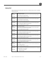
Table 2-7. Data Scope of User Reference Data
User Reference
Range
Scope
System
From any program, block, or host computer
%P
Program
From any block, but not from other programs
%L
Local
%I, %Q, %M, %T, %S, %SA, %SB,
%SC, %G, %R, %AI, %AQ,
convenience references, fault locating
references
From within a block only
In an LD block:
•
%P should be used for program references that are shared with other blocks.
•
%L are local references which can be used to restrict the use of register data to that block.
These local references are not available to other parts of the program.
%I, %Q, %M, %T, %S, %SA, %SB, %SC, %G, %R, %AI, and %AQ references are available
throughout the system.
Appendix C contains a Memory Allocation worksheet for determining the total number of bytes of
user data used and how much is still available for the user program.
2-16
Series 90™-70 System Manual for Control Software Users – November 1999
GFK-1192B
2
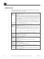
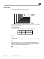
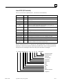
Data Types
Table 2-8. Data Types
Type
Name
Description
BOOL
Boolean
BYTE
Byte
A Byte data type has an 8-bit value. It has 256 values (0–255). A
BYTE string may have length N.
WORD
Word
A Word data type uses 16 consecutive bits of data memory. The
valid range of word values is 0000 hex to FFFF hex.
Data Format
A Boolean data type is the smallest unit of memory. It has two
states, 1 or 0. A BOOL string may have length N.
Register 1
(16 bit states)
16
DWORD
UINT
Double Word A Double Word data type has the same characteristics as a single
word data type, except that it uses 32 consecutive bits in data
memory instead of only 16 bits.
Unsigned
Integer
1
Register 2
32
17
16
(32 bit states)
DINT
REAL
BCD-4
BCD-8
MIXED
ASCII
Signed
Integer
Signed integers use 16-bit memory data locations, and are
represented in 2’s complement notation. The valid range of an
INT data type is –32768 to +32767.
Double
Precision
Integer
Double precision integers are stored in 32-bit data memory
locations (two consecutive 16-bit memory locations) and are
always signed values (bit 32 is the sign bit.) The valid range of a
DINT data type is –2147483648 to +2147483867.
FloatingPoint
Real numbers use 32 consecutive bits (two consecutive 16-bit
memory locations). The range of numbers that can be stored in
this format is from ± 1.401298E-45 to ± 3.402823E+38. Refer to
Appendix D “Using Floating-Point Math,” for IEEE format.
Four-Digit Four-digit BCD numbers use 16-bit data memory locations. Each
Binary Coded BCD digit uses four bits and can represent numbers between 0
Decimal
and 9. This BCD coding of the 16 bits has a legal value range of
0 to 9999.
EightDigit Binary
Coded
Decimal
Mixed
ASCII
Eight-digit BCD data types use two consecutive 16-bit data
memory locations (32 consecutive bits). Each BCD digit uses 4
bits per digit to represent numbers from 0 to 9. The complete
valid range of the 8-digit BCD data type is 0 to 99999999.
A Mixed data type is available only with the MUL and DIV
functions. The MUL function takes two integer inputs and
produces a double integer result. The DIV function takes a double
integer dividend and an integer divisor to product an integer
result.
Eight-bit encoded characters. A single reference is required to
make up 2 (packed) ASCII characters. The first character of the
pair corresponds to the low byte of the reference word. The
remaining 7 bits in each section are converted. Command codes
and non-displayable characters appear on the screen as
non-alphanumeric characters (for example, @).
1
Register 1
Unsigned integers use 16-bit memory data locations. They have a
valid range of 0 to +65535 (FFFF hex).
(Binary value)
16
INT
Register 1
1
Register 1
S
16
1
Register 2
s
32
(Two’s
Complement
value)
Register 1
17
16
(Binary value)
Register 2
32
Register 1
17
16
(IEEE format)
Register 1
4 3 2 1
13 9 5 1
7
6
1
(4 BCD digits)
Register 2
8
1
Register 1
5
4
3
8
1
32 29 25 21 17 16 13 9 5 1
(8 BCD digits)
16
16
32
=
32
16
16
=
S = Sign bit (0 = positive, 1 = negative).
GFK-1192B
Chapter 2 System Operation
2-17
2
Note
Using function blocks that are not explicitly bit-typed will affect transitions for
all bits in the written byte/word/dword.
Also for information about using floating-point numbers, refer to Appendix D,
Using Floating-Point Numbers.
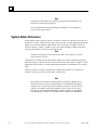
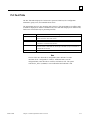
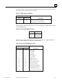
System Status References
System status references (formerly called “Convenience” references) in the Series 90-70 PLC are
assigned to %S, %SA, %SB, and %SC memory. They each have a system-supplied nickname that
enables you to enter the nickname rather than the exact %S reference. Examples of time tick
references include T_10MS, T_100MS, T_SEC, and T_MIN. Examples of other system status
references include FST_SCN, ALW_ON, and ALW_OFF.
Note
%S bits are read-only bits; do not write to these bits. You may, however, write to
%SA, %SB, and %SC bits.
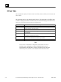
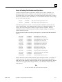
Listed below are available system status references that may be used in an application program.
When entering logic, either the reference or the nickname can be used. Refer to Chapter 3, “Fault
Explanation and Correction,” for more detailed fault descriptions and information on correcting
faults.
While it is possible to use these special names in another context, their use is restricted (for
example, you cannot use them as a block name or folder name).
Note
Most references not listed in the following table (for example, %S0002) are not
used for the Series 90-70 PLC. Products that have Genius Modular Redundancy
(CPU788, CPU789, and CPU790) have additional references, as do the CPU780,
CGR772, and CGR935 (with CPU redundancy). Refer to GFK-1277 for status
references for Genius Modular Redundancy (GMR), GFK-0827 for Hot Standby
CPU Redundancy, and GFK-1427 for Enhanced Hot Standby CPU Redundancy.
2-18
Series 90™-70 System Manual for Control Software Users – November 1999
GFK-1192B
2
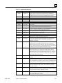
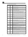
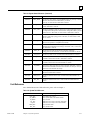
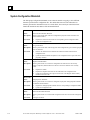
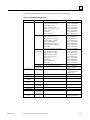
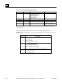
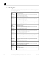
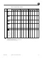
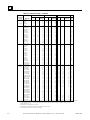
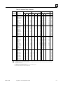
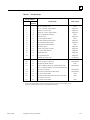
Table 2-9. System Status References
GFK-1192B
Reference
Name
Definition
%S0001
FST_SCN
Current sweep is the first sweep in which the LD or standalone C
program executed. Set the first time the user program is executed after a
Stop/Run transition and cleared upon completion of its execution.
%S0003
T_10MS
0.01 second timer contact.
%S0004
T_100MS
0.1 second timer contact.
%S0005
T_SEC
1.0 second timer contact.
%S0006
T_MIN
1.0 minute timer contact.
%S0007
ALW_ON
Always ON.
%S0008
ALW_OFF
Always OFF.
%S0009
SY_FULL
Set when the PLC fault table fills up (size configurable with a default
of 16 entries). Cleared when the PLC fault table is cleared.
%S0010
IO_FULL
Set when the I/O fault table fills up (size configurable with a default of
32 entries). Cleared when the I/O fault table is cleared.
%S0011
OVR_PRE
Set when an override exists in %I, %Q, %M, or %G memory.
%S0012
FRC_PRE
Set when force exists on a Genius point.
%S0013
PRG_CHK
Set when background program check is active.
%S0014
PLC_BAT
Set to indicate a bad battery in a Release 4 or later CPU. The contact is
updated when a change in the battery status occurs.
%S0121
FST_EXE
Current sweep is the first time this block has been called. Set when
transitioning from Stop to Run. FST_EXE is not available to
standalone C programs.
%SA0001
PB_SUM
Set when a checksum calculated on the application program does not
match the reference checksum. If the fault was due to a temporary
failure, the discrete bit can be cleared by again storing the program to
the CPU. If the fault was due to a hard RAM failure, then the CPU must
be replaced. Cleared when the PLC fault table is cleared.
%SA0002
OV_SWP
Set when the PLC detects that the previous sweep took longer than the
time specified by the user. Cleared when the PLC detects that the
previous sweep did not take longer than the specified time. It is also
cleared during the transition from Stop to Run mode. Only valid if the
PLC is in Constant Sweep or Microcycle Sweep mode. Also cleared
when the PLC fault table is cleared.
%SA0003
APL_FLT
Set when an application fault occurs. Cleared when the PLC fault table
is cleared.
%SA0009
CFG_MM
Set when a configuration mismatch is detected during system power-up
or during a store of the configuration. Cleared by powering up the PLC
when no mismatches are present or during a store of configuration that
matches hardware. Also cleared when the PLC fault table is cleared.
%SA0010
HRD_CPU
Set when the diagnostics detects a problem with the CPU hardware.
Cleared by replacing the CPU module. Also cleared when the PLC
fault table is cleared.
%SA0011
LOW_BAT
Set when a low battery fault occurs. Cleared by replacing the battery
and ensuring that the PLC powers up without the low battery condition.
. Also cleared when the PLC fault table is cleared.
%SA0012
LOS_RCK
Set when an expansion rack stops communicating with the PLC CPU.
Cleared by fixing the problem and power cycling the rack. Also cleared
when the PLC fault table is cleared
Chapter 2 System Operation
2-19
2
Table 2-9. System Status References (Continued)
Reference
Name
Definition
%SA0013
LOS_IOC
Set when a Bus Controller stops communicating with the PLC. Cleared by
replacing the module and cycling power on the rack containing the module, or
when the I/O fault table is cleared.
%SA0014
LOS_IOM
Set when an I/O module stops communicating with the PLC CPU. Cleared by
replacing the module and cycling power on the rack containing the module, or
when the I/O fault table is cleared.
%SA0015
LOS_SIO
Set when an option module stops communicating with the PLC CPU. Cleared
by replacing the module and cycling power on the rack containing the module,
or when the PLC fault table is cleared.
%SA0017
ADD_RCK
Set when an expansion rack is added to the system. Cleared by cycling power
on the rack containing the module and the configuration matches the
hardware after a store, or when the PLC fault table is cleared.
%SA0018
ADD_IOC
Set when a Bus Controller is added to a rack. Cleared by cycling power on the
rack containing the module and when the configuration matches the hardware
after a store, or when the I/O fault table is cleared, or when the I/O fault table
is cleared.
%SA0019
ADD_IOM
Set when an I/O module is added to a rack. Cleared by cycling power on the
rack containing the module and when the configuration matches the hardware
after a store.
%SA0020
ADD_SIO
Set when an option module is added to a rack. Cleared by cycling power on
the rack containing the module and when the configuration matches the
hardware after a store, or when the PLC fault table is cleared.
%SA0022
IOC_FLT
Set when a Bus Controller reports a bus fault, a global memory fault, or an
IOC hardware fault. Cleared by cycling power on the rack containing the
module and when the configuration matches the hardware after a store, or
when the I/O fault table is cleared.
%SA0023
IOM_FLT
Set when an I/O module reports a circuit or module fault. Cleared by cycling
power on the rack containing the module and when the configuration matches
the hardware after a store, or when the I/O fault table is cleared.
%SA0027
HRD_SIO
Set when a hardware failure is detected in an option module. Cleared by
replacing the module and cycling power on the rack containing the module, or
when the PLC fault table is cleared.
%SA0029
SFT_IOC
Set when there is a software failure in the I/O Controller, or when the I/O
fault table is cleared.
%SA0031
SFT_SIO
Set when an option module detects an internal software error. Cleared by
cycling power on the main rack and when the configuration matches the
hardware, or when the PLC fault table is cleared.
%SA0032
SBUS_ER
Set when a bus error occurs on the VME bus backplane. Cleared by cycling
power on the main rack.
Set when a user-defined fault is logged in the PLC fault table. These bits are
cleared when the PLC fault table is cleared.
%SB0001
WIND_ER
Set when there is not enough time to start the Programmer Window in
Constant Sweep or Microcycle Sweep mode, or when there is not enough time
to start the Logic Window in Microcycle Sweep mode. Cleared when the PLC
detects that the previous sweep did have enough time to perform the window.
%SB0009
NO_PROG
Set when the PLC CPU powers up with memory preserved, but no user
program is present. Cleared when the PLC powers up with a program present,
or when the PLC fault table is cleared.
%SA0081 –
%SA0112
2-20
Series 90™-70 System Manual for Control Software Users – November 1999
GFK-1192B
2
Table 2-9. System Status References (Continued)
Reference
Name
Definition
%SB0010
BAD_RAM
Set when the CPU detects corrupted RAM memory at power-up. Cleared
when the CPU detects that RAM memory is valid at
power-up, or when the PLC fault table is cleared.
%SB0011
BAD_PWD
Set when a password access violation occurs. Cleared when
the PLC fault table is cleared.
%SB0012
NUL_CFG
Set when an attempt is made to put the PLC in Run mode when there is
no configuration data present. Cleared when configuration data is present
and the PLC is in Run mode, or when the PLC fault table is cleared.
%SB0013
SFT_CPU
Set when the CPU detects an error in the CPU operating system
software. Cleared by cycling power to the CPU, or when the PLC fault
table is cleared.
%SB0014
STOR_ER
Set when an error occurs during a programmer store operation. Cleared
when a store operation is completed successfully.
%SB0016
MAX_IOC
Set when more than 32 IOCs are configured for the system. Cleared by
modifying the configuration and storing it to the PLC CPU, or when the
PLC fault table is cleared.
%SB0017
SBUS_FL
Set when the PLC fails to gain access to the bus. Cleared by
cycling power on the main rack, or when the PLC fault table is cleared.
%SC0009
ANY_FLT
Set when any fault occurs. Cleared when both fault tables are cleared.
%SC0010
SY_FLT
Set when any fault occurs that causes an entry to be placed in the PLC
fault table. Cleared when the PLC fault table is cleared.
%SC0011
IO_FLT
Set when any fault occurs that causes an entry to be placed in the I/O
fault table. Cleared when the I/O fault table is cleared.
%SC0012
SY_PRES
Set as long as there is at least one entry in the PLC fault table. Cleared
when the PLC fault table is cleared. Once the bit is set on by an error, it
will not be reset until after the sweep.
%SC0013
IO_PRES
Set as long as there is at least one entry in the I/O fault table. Cleared
when the I/O fault table is cleared.
%SC0014
HRD_FLT
Set when a hardware fault occurs. Cleared when both fault tables are
cleared.
%SC0015
SFT_FLT
Set when a software fault occurs. Cleared when both fault tables are
cleared.
Fault References
For a detailed discussion of fault references, please refer to Chapter 3.
Table 2-10. System Fault References
GFK-1192B
System Fault Reference
Description
ANY_FLT
SY_PRES
IO_PRES
SY_FLT
IO_FLT
HRD_FLT
SFT_FLT
Any fault in the system
Any system fault in the Series 90 PLC
Any I/O fault
Indicates a new entry in the PLC fault table
Indicates a new entry in the I/O fault table
Any hardware fault
Any software fault
Chapter 2 System Operation
2-21
2
Table 2-11. Configurable Fault References
Configurable Fault
References
(Default Action)
2-22
Description
SBUS_ER (diagnostic)
System bus error. (The BSERR signal was generated on the VME system
bus.)
HRD_CPU (fatal)
PLC CPU hardware fault, such as failed memory device or failed serial port.
HRD_SIO (diagnostic)
Non-fatal hardware fault on any module in the system, such as the failure of a
serial port on a PCM.
SFT_IOC (diagnostic)
Non-recoverable software error in a Genius Bus Controller.
SFT_SIO (diagnostic)
Non-recoverable software error in a PCM or LAN interface module.
PB_SUM (fatal)
Program or block checksum failure during power-up or in Run mode.
LOW_BAT (diagnostic)
Low battery signal from CPU or another module in the system.
OV_SWP (diagnostic)
Constant sweep time exceeded.
SY_FULL, IO_FULL
(diagnostic)
PLC fault table full (configurable with a default of 16 entries).
I/O fault table full (configurable with a default of 32 entries).
APL_FLT (diagnostic)
Application fault.
LOS_RCK (diagnostic)
Loss of rack (BRM failure, loss of power) or missing a configured rack.
LOS_IOC (diagnostic)
Loss of Bus Controller channel or missing a configured Bus Controller.
LOS_IOM (diagnostic)
Loss of I/O module (does not respond) or missing a configured I/O module.
LOS_SIO (diagnostic)
Loss of option module (does not respond) or missing a configured module.
ADD_RCK (diagnostic)
New rack added or previously faulted rack has returned.
ADD_IOC (diagnostic)
Previously faulted Bus Controller is no longer faulted.
ADD_IOM (diagnostic)
Previously faulted I/O module is no longer faulted.
ADD_SIO (diagnostic)
New option module is added or previously faulted module no longer faulted.
IOC_FLT (diagnostic)
Non-fatal bus or Bus Controller error—more than 10 bus errors in 10 seconds
(error rate is configurable).
IOM_FLT (diagnostic)
Point or channel on an I/O module—a partial failure of the module.
CFG_MM (fatal)
Wrong module type detected during power-up or Run mode. The PLC does
not check the configuration parameters set up for individual modules such as
Genius I/O blocks.
Series 90™-70 System Manual for Control Software Users – November 1999
GFK-1192B
2
Table 2-12. Non-Configurable Faults
NonConfigurable Faults
Description
SBUS_FL (fatal)
System bus failure. The PLC CPU was not able to access the VME bus.
BUSGRT-NMI error.
NO_PROG (information)
No application program is present at power-up. Should only occur the first
time the PLC is powered up or if the battery-backed RAM containing the
program fails.
BAD_RAM (fatal)
Corrupted program memory at power-up. Program could not be read and/or
did not pass checksum tests.
WIND_ER (information)
Window completion error. Servicing of Programmer or Logic Window was
skipped. Occurs in Constant Sweep or Microcycle Sweep mode.
BAD_PWD (information)
Change of privilege level request to a protection level was denied; bad
password.
NUL_CFG (fatal)
No configuration present upon transition to Run mode. Running without a
configuration is equivalent to suspending the I/O scans.
SFT_CPU (fatal)
CPU software fault. A non-recoverable error has been detected in the CPU.
May be caused by Watchdog Timer expiring.
MAX_IOC (fatal)
The maximum number of bus controllers has been exceeded. The Series 90
PLC supports 32 bus controllers.
STOR_ER (fatal)
Download of data to PLC from the programmer failed; some data in PLC may
be corrupted.
Note
Fault and FIP locating references are discussed in Chapter 3, section 1 of this manual
Refer to the Series 90™ Sequential Function Chart Programming Language User’s
Manual (GFK-0854) for SFC references.
GFK-1192B
Chapter 2 System Operation
2-23
2
Section 3: Program Organization
The user program(s) contains the logic that is used to process input data and control output data.
Program logic is executed repeatedly by the PLC. The Series 90-70 PLC allows up to 16 user
programs, with a maximum of 1 LD program. Refer to Tables 2-4 and 2-5 for a listing of program
sizes and reference limits for each CPU model.
The following figure depicts 3 user programs, two of which are standalone C programs. The LD
program consists of four blocks (_MAIN, LD_1, PSB_X, and EXT4). The figure further illustrates
the scoping of various memory types: all references except %P and %L are visible to the
standalone programs; %P memory is visible to all of the program blocks, and the LD_1 block has
its own local data, %L. Details of standalone programs and blocks are described later in this
section.
Program “A” (Standalone)
Program “B” (RLD)
Program “C” (Standalone)
_MAIN
%P Memory
LD_1
%L
PSB_X
EXT4
User Data References (%I, %Q, %R, %AI, %AQ, etc.)
2-24
Series 90™-70 System Manual for Control Software Users – November 1999
GFK-1192B
2
Ladder Logic Programming
An LD program for the Series 90-70 PLC consists of one or more units called blocks. Four types
of blocks are supported by the Series 90-70 PLC:
Table 2-13. Block Types
Number of
Parameter
Pairs
Block
Type
Programming
Language
LD
Ladder Logic
32 KB in
Control*
n/a
SFC
Ladder
Logic/SFC
32 KB in
Control*
n/a
PSB
Ladder Logic
32 KB in
Control*
0–7
External
C
64,000 bytes
0–7
Size Limit
Notes
SFC blocks cannot be used as
Interrupt blocks.
External blocks cannot call any
other blocks. External blocks
are created using the C
Programmer’s Toolkit.
*When running in Logicmaster compatibility mode, the limit is 16 KB.
•
SFC programming is described in detail in the Series 90 Sequential Function Chart
Programming Language User’s Manual, GFK-0854. Sequential Function Chart (SFC) is an
IEC-compliant, graphical, state language specifically designed for controlling sequential
processes.
•
LD (also known as Relay Logic Diagram language) is the language used in the LD Editor
window within Control and in Logicmaster.
•
PSB (Parameterized Subroutine Blocks) are LD blocks that have input and output parameters.
Note
Up to 255 blocks can be used. The maximum number of block calls that can be
programmed within a given block is 64. The maximum number of programmed
calls to a particular block is 255. (A block can be executed any number of times,
but there cannot be more than 255 explicit calls to any given block.)
GFK-1192B
Chapter 2 System Operation
2-25
2
Main Block
When using an LD program there is always a _MAIN block. LD program execution begins with
the _MAIN block.
read
inputs
_MAIN
BLOCK
write
2-26
outputs
Series 90™-70 System Manual for Control Software Users – November 1999
GFK-1192B
2
Blocks
Structuring a program as blocks enables you to reuse logic. Logic that needs to be repeated can be
entered in a block. Calls would then be made to that block to execute the logic. In this way, total
program size is reduced. Dividing a program into smaller blocks also simplifies programming and
reduces the overall amount of logic needed for the program.
Examples of Using Blocks
As an example, the logic for an LD program could be divided into three blocks, each of which
could be called as needed from the _MAIN block. (A block cannot call the _MAIN block.) In this
example, the _MAIN block might contain little logic, serving primarily to sequence the other
blocks.
read
inputs
_ MAIN
BLOCK
write
BLOCK
2
outputs
BLOCK
3
BLOCK
4
GFK-1192B
Chapter 2 System Operation
2-27
2
A block can be used many times as the program executes. Logic that needs to be repeated several
times in a program could be entered in a block. Calls would then be made to that block to access
the logic.
read
inputs
_MAIN
BLOCK
write
2-28
BLOCK
2
outputs
Series 90™-70 System Manual for Control Software Users – November 1999
GFK-1192B
2
In addition to being called from the _MAIN block, blocks can also be called by other blocks. A
block may even call itself.
read
inputs
_ MAIN
BLOCK
write
BLOCK
2
outputs
BLOCK
3
BLOCK
5
BLOCK
4
There may be no limit to the number of levels of calls to blocks that your programming software
will allow. However, the PLC will only allow a certain number of nested calls before an
“Application Stack Overflow” fault is logged and the PLC transitions to Stop/Fault mode. The call
depth is guaranteed to be at least four on the 731 and 732 CPUs and eight on all other models.
The actual call depth allowed depends on the amount of data (non-boolean) flow used in the
blocks. If less than the 171 word data flow limit is used, then more nested calls may be made. The
call level nesting counts the _MAIN block as level 1. The illustration above shows three levels of
calls.
Note
Before a block can be used, you need to define it in the block declarations. For
information on block declarations, refer to the documentation of your
programming software.
GFK-1192B
Chapter 2 System Operation
2-29
2
How Blocks Are Called
A block executes when called from the program logic in the _MAIN block or another block.
|
___________
| |
|
|——| CALL PBK1 |
| |___________|
|
_____________
|%I00500 %Q00076 |
|
|——| |—————| |———| CALL PBK2 |
|
|_____________|
|
In the example above, PBK1 will always be called. Conditional logic can be used to control
calling the block. In order for PBK2 to be called, both input %I00500 and output %Q00076 must
be ON.
2-30
Series 90™-70 System Manual for Control Software Users – November 1999
GFK-1192B
2
Blocks and Local Data
Each block in the LD program can have an associated data block. The _MAIN data block is
referenced by %P; all other data blocks are referenced by %L.
The size of the data block is dependent on the highest reference in its block for %L and in all
blocks for %P. Appendix C, “Memory Allocation,” provides a worksheet for determining the total
number of bytes of user data used and how much is still available for the user program.
data
%P
data
%L
_MAIN
BLOCK
2
BLOCK
data
%L
BLOCK
3
data
%L
BLOCK
4
All blocks within the LD program can use data associated with the _MAIN block (%P). Blocks
can use their own %L references as well as the %P references that are available to all blocks. The
_MAIN block cannot use %L.
Note
External blocks and Parameterized Subroutine Blocks do not have their own %L
data; instead, they inherit the %L data of the calling block.
GFK-1192B
Chapter 2 System Operation
2-31
2
Parameterized Subroutine Blocks
A Parameterized Subroutine Block (PSB) is an optional, user-defined function block, configured
with between zero and seven input/output parameter pairs.
As with other blocks, Parameterized Subroutine Blocks can be called by the _MAIN block, other
blocks, or itself. The calling block may pass parameters to the Parameterized Subroutine Block.
When a Parameterized Subroutine Block is declared, it must be assigned a unique block name
along with the number, type, and length of the parameters. Each parameter, other than the Enable
and Enable Out parameters, is designated as a BOOL, WORD, or NWORD type, along with a
specified length. BOOL lengths range from 1 to 256; WORD and NWORD lengths range from 1
to 512. Default is one bit for BOOL lengths or one word for WORD and NWORD lengths. In
addition, you may also declare an optional three-character formal parameter reference name.
Parameterized Subroutine Blocks and Local Data
Parameterized Subroutine Blocks support the use of %P global data. Parameterized Subroutine
Blocks do not have their own %L data, but instead inherit the %L data of the calling block.
Parameterized Subroutine Blocks also inherit %S contacts, such as FST_EXE, from the calling
block. If %L references are used within a Parameterized Subroutine Block and the block is called
by _MAIN, %L references will be inherited from the %P references wherever encountered in the
Parameterized Subroutine Block (for example, %L0005 = %P0005).
data
%P
Inherits as %L
_MAIN
BLOCK
PSB 1
data
%L
Inherits as %L
BLOCK
1
2-32
Series 90™-70 System Manual for Control Software Users – November 1999
PSB 2
GFK-1192B
2
How Parameterized Subroutine Blocks Are Called
A Parameterized Subroutine Block executes when called from the program logic in the _MAIN
block, another block, or itself.
In the following example, if %I00001 is set, the parameterized subroutine named LOAD_41 is
executed. The LOAD_41 subroutine block operates on the input data (located at reference
addresses %I00100 – %I00111 and %I00001 – %I00016) and produces values in the block of
output data (located at reference addresses %T00001 – %T00016, and at register memory
addresses %R00200 – %R00201). The logic within the subroutine can also control the OK output
of the Parameterized Subroutine Block. This example shows the subroutine CALL instruction as it
will appear in the calling block.
|
______________
|%I00001
|
|
%Q00001
|——| |—————| CALL LOAD_41 |————————————————————————————————————————————————()—
|
| (SUBROUTINE) |
|
|B012
B016|
| %I00100 —|ABC
Y1|—%T00001
|
|
|
|
|B016
W002|
| %I00001 —|X2
Y2|—%R00200
|
|______________|
|
GFK-1192B
Chapter 2 System Operation
2-33
2
Referencing Formal Parameters Within a Parameterized Subroutine Block
Formal parameters are those parameters used within Parameterized Subroutine Block that are
passed from and to the calling block. They are either BOOL, WORD, or NWORD types. NWORD
type parameters may be used on any multiword type operands, but not on discrete types. (An
NWORD is a number of words passed into a Parameterized Subroutine Block).
The formal parameters are identified as X input parameters or Y output parameters, followed by
the number of the input or output parameter, respectively. For example, X2 indicates the
parameter used at location X2 in the parameterized subroutine declaration. The X2 label could be
followed by a value of 1 to 16 to the length provided in the subroutine declaration (B016).
Up to seven formal parameter pairs may be declared in a Parameterized Subroutine Block. The
formal parameter type, number, and length use the form:
ab[ccc]
where:
a=X
a=Y
b
c
denotes an input formal parameter.
denotes an output formal parameter.
is a parameter number between 1 and 7.
is a valid BOOL, WORD, or NWORD index.
The labels X1 through X7 and Y1 through Y7 may be assigned a nickname of up to three
characters.
Assigned parameters are PLC references or data flow that pass their address or data into or out of
a Parameterized Subroutine Block. An assigned parameter may pass either the value of the data in
the assigned parameter (BOOL type parameters) or the address of the assigned parameter (WORD
or NWORD type parameters). Assigned parameters are defined in a parameter assignment table.
2-34
Series 90™-70 System Manual for Control Software Users – November 1999
GFK-1192B
2
Restrictions on Formal Parameters within a Parameterized Subroutine Block
In general, formal BOOL parameters are allowed on all contacts, coils, and function block
parameters that allow discrete references (%I, %Q, %M, %T, %S, %G, and %U). Formal WORD
and NWORD parameters are allowed on all function block parameters that allow register
references (%R, %AI, %AQ, %P, %L, and %UR). NWORDS should not be used in Control. The
type exists only to maintain compatibility with folders created through Logicmaster and imported
into a Control folder. In Logicmaster, NWORD parameters are allowed only on multiword type
parameters (that is, DINT, DWORD, or REAL). (An NWORD is a number of words passed into a
Parameterized Subroutine Block.)
The following list contains several exceptions and restrictions that have been identified when
using formal parameters within a Parameterized Subroutine Block:
1.
Transitional contacts, transitional coils, and retentive coils are not allowed with formal
parameters. The editor (that is, the editor tool within the programming package) will
substitute the non-retentive equivalent of these functions,
+–––(M), +–––(SM), and +–––(/M) and display an appropriate warning message.
2.
Formal BOOL input parameters cannot be used as output parameters on a function block.
3.
The DO I/O function is not allowed with formal parameters.
4.
Multiword type function block parameters (that is, DINT, DWORD, or REAL) are only
allowed with formal NWORD parameters.
5.
Formal parameters are not allowed on the following function block parameters:
Function
GFK-1192B
Parameter
Service Request (Service Request)
PARMS input parameter.
Communications Request (COMMREQ)
IN input parameter.
DATA_INIT
DATA_INIT_COMM
DATA_INIT_PID
DATA_INIT_ASCII
Q output parameter.
6.
A Parameterized Subroutine Block’s BOOL type formal parameters may not be passed to
another Parameterized Subroutine Block.
7.
WORD formal parameters cannot be passed into another Parameterized Subroutine
Block’s NWORD input parameter.
Chapter 2 System Operation
2-35
2
External Blocks
External blocks are created using the C Programmer’s Toolkit. Refer to the C Programmer’s
Toolkit for Series 90™ PLCs (GFK-0646) for detailed information regarding external blocks.
How External Blocks Are Called
External blocks are added to a user program by using the Librarian function in your programming
software.
An external block executes when called from the program logic in the _MAIN block or from
another block. To facilitate the passing and returning of data, an external block may have 0 to 7
parameter pairs.
In the following example, if %I00001 is set, the external block named EXT_11 is executed. The
block operates on the input data, located at reference addresses %I00100 – %I00111 and
%I00001 – %I00016, and produces values in the block of output data, located at reference
addresses %T00001 – %T00016, and at register memory addresses %R00200 – %R00201. The
logic within the block can also control the Enable Out output of the external block.
|
______________
|%I00001
|
|
%Q00001
|——| |—————| CALL EXT_11 |————————————————————————————————————————————————()—
|
| (EXTERNAL) |
|
|
|
| %I00100 –|X1
X1|–%T00001
|
|
|
|
|
|
| %I00001 –|X2
X2|–%R00200
|
|______________|
|
Note
Unlike other block types, external blocks cannot call any other blocks.
2-36
Series 90™-70 System Manual for Control Software Users – November 1999
GFK-1192B
2
External Blocks and Local Data
External blocks support the use of %P global data. External blocks do not have their own %L
data, but instead inherit the %L data of the calling block. External blocks also inherit %S
contacts, such as FST_EXE, from the calling block. If %L references are used within an external
block and the block is called by _MAIN, %L references will be inherited from the %P references
wherever encountered in the external block (for example, %L0005 = %P0005).
data
%P
Inherits as %L
_MAIN
BLOCK
EXT 1
data
%L
Inherits as %L
BLOCK
1
EXT 2
Local Data Initialization
When an external block is stored to the PLC, a copy of most of its internal data is saved. Global
and static initialized data are saved, but if static variables are declared without an initial value, the
initial value is undefined and must be initialized by the C application. (Refer to the “Global
Variable Initialization” and “Static Variable” parts in Section 6 of Chapter 2 of the C
Programmer’s Toolkit for Series 90™ PLCs (GFK-0646). This data is used to reinitialize the
block’s data area whenever the PLC transitions from Stop to Run.
External/standalone programs do not use %L data, but the internal data they use is somewhat
similar to local data, as discussed above. Internal data used in a standalone program should not be
confused with %L data.
GFK-1192B
Chapter 2 System Operation
2-37
2
Standalone C Programs
Like external blocks, standalone programs are developed using the C Programmer’s Toolkit.
Unlike external blocks, however, standalone C Programs can be up to 512 KB in size. Standalone
C programs cannot call other standalone programs, nor can they call blocks within an LD
program. Similarly, blocks within an LD program cannot call a standalone program. Instead,
standalone C programs are scheduled for execution using one of several possible program
scheduling modes, described in section 4 of this chapter.
A maximum of 16 standalone programs can be used at one time. If an LD program is used, only
15 standalone programs are allowed, for a total of 16 programs.
Note
Since standalone C programs are truly separate programs, they do not have
access to memory types local to an LD program (%L and %P). The internal or
local data used in a standalone C program should not be confused with %L and
%P data.
Data Encapsulation
Each standalone C program is provided with a means of obtaining its own local copy of user data
references. Instead of operating on the global set of user references, each standalone program can
operate on its own local set of data. This feature is supported through the use of an input/output
specification.
The following steps occur when using an I/O specification with a standalone C program:
1.
When the program is scheduled for execution, any corresponding input specification is copied
from the global user reference data area(s) to an area local to the program.
2.
As the program executes, it can operate on its local set of input and output data. Any
interruptions during the execution phase will not affect this program’s local copies of input or
output data.
3.
When the program completes, its local output specification is copied back to the specified set
of user data reference areas.
Two particular concerns are addressed by using an input/output specification. First, if a program
is suspended in mid-execution and an output scan is performed before execution is resumed,
output values will remain consistent since the output scan values are obtained from the user data
reference locations. Second, if a program is interrupted mid-execution by another program, the
first program is unaffected by changes to global data caused by the second program, since it has its
own local copy of data.
Another benefit to using an input specification is to provide a more accurate sampling of input
values. If a program’s execution is postponed due to higher priority programs, the input
specification may provide the program with a set of data that more accurately represents the state
of that data when the program was scheduled since global user reference data may have been
modified by higher priority programs or by the scanning of input values.
2-38
Series 90™-70 System Manual for Control Software Users – November 1999
GFK-1192B
2
Input/Output Specifications
Unlike external blocks, standalone C and LD programs cannot have any input or output
parameters. Standalone C programs may utilize an input/output specification that lists a
maximum of eight input and eight output ranges. The input ranges will be copied to the program
at the start of program execution. The output ranges are copied from the standalone C program to
the global reference on the completion of program execution. Note that this differs from external
block parameters that are passed by reference, not by value. This operation is especially important
for programs that may be time-sliced over multiple sweeps, which can occur when using
Microcycle Sweep mode1.
Caution
When the PLC runs in Microcycle Sweep mode, programs can be suspended
in the middle of execution, possibly in the middle of a line of C code or in
the middle of a rung of logic or function block. If the program uses global
references such as %Q, %R, etc., a possibly inconsistent set of reference
values may be present at the time an Interrupt program or output scan
occurs. This inconsistency could even be within a given reference value if
the value is not accessed according to its type.
1
Incoherent data can result if a program uses global data and is suspended across multiple
sweeps. The data referenced will be from two successive sweeps. Although data cannot be
incoherent within a byte or word, global data should only be accessed using its basic type (byte,
word, etc.), otherwise incoherency can apply to individual elements as well.
GFK-1192B
Chapter 2 System Operation
2-39
2
To illustrate the possibility of inconsistent output data, consider the following example program
which updates a given output value in several locations. For this example, assume that the user
has configured %AQ1 as an output specification from the second program, and that user reference
%AQ1 contains the value 0 when the two programs begin execution.
Differences Between Accessing Global and Local (Internal) Data
Program Accessing Global Data
Program Using I/O
Specification
<program begins>
<program begins>
%AQ1 = 0
An output scan occurring after
this line of code would output
a 0 to AQ1.
LOC[1] = 0
An output scan occurring after
this line of code would output a
0 to AQ1.
%AQ1 = %AQ1 + 2
An output scan occurring after
this line of code would output
a 2 to AQ1.
LOC[1] = LOC[1]+2
An output scan occurring after
this line of code would output a
0 to AQ1.
%AQ1 = %AQ1 + 12
An output scan occurring after
this line of code would output
a 14 to AQ1.
LOC[1]=LOC[1] + 12
An output scan occurring after
this line of code would output a
0 to AQ1.
%AQ1 = %AQ1 / 2
An output scan occurring after
this line of code would output
a 7 to AQ1.
LOC[1]=LOC[1]/2
An output scan occurring after
this line of code would output a
0 to AQ1.
<program completes>
<program completes>
The PLC copies the output specification from a local area
back to the global areas when the program completes.
Further output scans will output a 7 to AQ1.
Further output scans will output a 7 to AQ1.
Note
Remember that standalone C programs are truly separate programs. They do not
have access to memory types local to an LD program (%L and %P). The internal
or “local” data used in a standalone C program should not be confused with %L
and %P data.
2-40
Series 90™-70 System Manual for Control Software Users – November 1999
GFK-1192B
2
Standalone C Programs and Local Data
Standalone C programs do not have a local data copy provided by the PLC. Similarly, they are not
able to access %P memory of an LD program, nor can they access any %L memory associated
with a block within an LD program. Standalone C programs do have local data that is declared
within the C source file(s) used to create the standalone C program. Refer to the C Programmer’s
Toolkit User’s Manual (GFK-0646) for further information.
Local Data Initialization
When a standalone C program is stored to the PLC, a copy of its internal data is saved. This data
is used to reinitialize the program’s data area whenever the PLC transitions from Stop to Run.
GFK-1192B
Chapter 2 System Operation
2-41
2
Referencing I/O Specification Data Within a Standalone C Program
Several new C macros used to define and access input and output specification data are defined for
standalone C programs. Refer to the C Programmer’s Toolkit User’s Manual (GFK-0646, revision
C or later) for information regarding referencing I/O specification data within a standalone C
program.
Data Coherency of I/O Specifications
Since standalone C programs can be interrupted by other programs and Interrupt blocks, data
incoherency within an I/O specification can occur. Each individual I/O specification is limited to
2048 bytes, for a maximum of 16KB of input data and 16KB of output data. The 90-70 PLC will
ensure the following:
•
Each byte within an individual I/O specification is coherent with respect to that individual
specification.
•
If the total length of all input specifications is no more than 2048 bytes, the entire input
specification will be coherent.
•
If the total length of all output specifications is no more than 2048 bytes, the entire output
specification will be coherent.
If the total length of an input or output specification exceeds 2048 bytes, groups of individual
specifications whose combined lengths do not exceed 2048 bytes will be coherent. The following
table indicates coherency in this case.
Table 2-14. Coherency of I/O Specification
I/O specification
Length (bytes)
1
2000
2
48
Interrupts may occur
3
1024
Interrupts may occur
4
1026
Interrupts may occur
2-42
5
10
6
20
7
20
8
20
Series 90™-70 System Manual for Control Software Users – November 1999
GFK-1192B
2
Using LD vs. Standalone C Programs
Several options need to be considered when determining which type of program is to be used. The
following list summarizes many of the features supported in each of the types of programs:
•
Interrupt Blocks are preferred over standalone programs when interrupt latency is a concern.
The overhead to process an Interrupt Standalone program is much larger than that of an
Interrupt block.
•
LD programs may operate only on global user reference data. This can introduce data
coherency problems when the LD program is run in Microcycle Sweep mode and the program
is suspended over multiple sweeps.
•
Standalone C programs incur an 8K overhead per program.
•
An LD program is preferred over a standalone C program when you are using large amounts
of boolean instructions. LD programs are better suited for relay type logic than are standalone
C programs.
Table 2-15. LD vs. Standalone C Program Tradeoffs
Programming
Language
Program Size
Limit
Data Types
Accessible
Local Data
Size
Scheduling
Modes
Data
Encapsulation
All
8k %P, 8K %L
per block
All*
No
LD
SFC
PSB
External
unlimited,
counts as part
of program
size
All *
Yes
n/a
LD
Ladder
Logic
smaller of
512K or
available
memory size,
organized
into16K
blocks.
Standalone
C, using the C
Programmer’s
Toolkit.
smaller of
512K or
available
memory size
All except
%P, %L
Block Types
Supported
*Using Microcycle Sweep mode with an LD program is not recommended. LD programs always operate on global data directly,
which can lead to inconsistent output values if the LD program is suspended mid-execution. Refer to section 4 of this chapter for
more information on Microcycle Sweep mode.
Differences in Operation: LD and Standalone C Programs
Retentiveness of Data
When only standalone C programs are used, the retentive nature of data is based solely on
memory type since there are no coil instructions. In this case %Q and %M are retentive. If both
LD and standalone C programs are used, the retentive property of memory types is driven by their
use in the LD program. For more information about retention of logic and data, refer to the
“Retentiveness of Logic and Data” discussion in section 2 of this chapter. For more information
on retentive properties of specific memory types, refer to the Table 2-3.
GFK-1192B
Chapter 2 System Operation
2-43
2
Global Data
LD programs only have access to global data areas since they do not have the ability to use
input/output specifications. This can lead to inconsistent output values if an LD program is used
in Microcycle Sweep mode.
Interrupt Execution
Interrupt blocks within the LD program have the highest priority in the system. In addition, they
cannot be preempted, while standalone C programs can be.
Queuing of Interrupts
The 90-70 PLC can queue the invoking of Interrupt blocks within the LD program. A standalone
C program triggered by an interrupt will not be queued should another interrupt occur during the
processing of the first interrupt. In this case a fault will be logged in the PLC fault table.
System Status References
The following differences exist when using System Status References* (called “Convenience
References” in previous editions of 90-70 Reference manual):
•
The reference FST_EXE is not available to standalone C programs.
•
The reference FST_SCN does not refer to %S0001 within standalone C programs. Instead, a
macro is provided by the C Toolkit to provide identical functionality.
*For information on System Status References, refer to Table 2-9 as well as section 2 of this
chapter.
2-44
Series 90™-70 System Manual for Control Software Users – November 1999
GFK-1192B
2
Section 4: PLC Sweep Modes and Program Scheduling Modes
Normal Sweep Mode
In Normal Sweep mode, each PLC sweep can consume a variable amount of time. The Logic
Window is executed in its entirety each sweep. The Communications and Background Windows
can be set to execute in a Limited or Run-to-Completion mode. Normal Sweep is the most
common sweep mode used for PLC applications.
The following figure illustrates three successive PLC sweeps in Normal Sweep mode. Note that
the total sweep times may vary due to sweep-to-sweep variations in the Logic Window,
Communications Windows, and Background Window.
a45529
SWEEP n
SWEEP n+1
SWEEP n+2
HK
HK
HK
INPUT
INPUT
INPUT
LOGIC
LOGIC
LOGIC
OUTPUT
PRG
OUTPUT
PRG
SYS
SYS
BG
BG
OUTPUT
PRG
SYS
Abbreviations:
HK = Housekeeping
BG
PRG = Programmer Window
SYS = System Communications Window
BG = Background Window
Figure 2-3. Typical Sweeps in Normal Sweep Mode
GFK-1192B
Chapter 2 System Operation
2-45
2
Constant Sweep Mode
In Constant Sweep mode, each PLC sweep begins at a specified Constant Sweep time after the
previous PLC sweep began. The Logic Window is executed in its entirety each sweep. If there is
sufficient time at the end of the sweep, the PLC will alternate among the Programmer
Communications, System Communications, and Background Windows, allowing them to execute
in Run-to-Completion mode until it is time for the next sweep to begin. Some or all of the
Communications and Background Windows may not be executed. The Communications and
Background Windows will terminate when the overall PLC sweep time has reached the value
specified as the Constant Sweep time.
One reason for using Constant Sweep mode is to ensure that I/O are updated at constant intervals.
The value of the Constant Sweep timer can be configured to be any value from 3 to 255
milliseconds. The Constant Sweep timer value may also be set and Constant Sweep mode may be
enabled or disabled by your programming software or by the user program using Service Request
function #1. The Constant Sweep timer has no default value; a timer value must be set prior to or
at the same time Constant Sweep mode is enabled.
If the PLC sweep exceeds the Constant Sweep time in a given sweep, the PLC places an
oversweep alarm in the PLC fault table and sets the OV_SWP (%SA0002) status reference at the
beginning of the next sweep. The OV_SWP status reference is reset when the time of the last
sweep does not exceed the Constant Sweep timer or the PLC is not in Constant Sweep mode.
Additional sweep time due to an oversweep condition in a given sweep does not affect the time
given to the next sweep.
2-46
Series 90™-70 System Manual for Control Software Users – November 1999
GFK-1192B
2
The following figure illustrates four successive PLC sweeps in Constant Sweep mode with a
Constant Sweep time of 100 milliseconds. Note that the total sweep time is constant, but an
oversweep may occur due to the Logic Window taking longer than normal.
a45530
SWEEP n
t = 0 ms
SWEEP n+2
t = 220 ms
SWEEP n+1
t = 100 ms
HK
HK
HK
HK
INPUT
INPUT
INPUT
INPUT
LOGIC
LOGIC
LOGIC
LOGIC
OUTPUT
Constant
Sweep
Time
SWEEP n+3
t = 320 ms
OUTPUT
PRG
PRG
OUTPUT
SYS
SYS
PRG
SYS
BG
BG
PRG
PRG
SYS
BG
BG
PRG
SYS
Abbreviations:
OUTPUT
HK = Housekeeping
PRG = Programmer Window.
SYS = System Communications Window.
BG = Background Window
20 ms oversweep
Figure 2-4. Typical Sweeps in Constant Sweep Mode
Constant Window Mode
In Constant Window mode, each PLC sweep can consume a variable amount of time. The Logic
Window is executed in its entirety each sweep. In this mode, the PLC will alternate among the
three windows, allowing them to run in a Run-to-Completion mode for a time equal to the value
set for the Constant Window timer. The overall PLC sweep time is equal to the time required to
execute the Housekeeping, Input Scan, Logic Window, and Output Scan phases of the sweep plus
the value of the Constant Window timer. This time may vary due to sweep-to-sweep variances in
the execution time of the Logic Window.
An application that requires a certain amount of time between the Output Scan and the Input
Scan, permitting inputs to settle after receiving output data from the program, would be ideal for
Constant Window mode.
The value of the Constant Window timer can be configured to be any value from 5 to 255
milliseconds. The Constant Window timer value may also be set by your programming software or
by the user program using Service Request functions #3, #4, and #5.
The following figure illustrates three successive PLC sweeps in Constant Window mode. Note that
the total sweep times may vary due to sweep-to-sweep variations in the Logic Window, but the
GFK-1192B
Chapter 2 System Operation
2-47
2
time given to the Communications and Background Windows is constant. Some of the
Communications or Background Windows may be skipped, suspended, or run multiple times
based on the Constant Window time.
SWEEP n
SWEEP
SWEEP
HK
HK
HK
INPUT
INPUT
INPUT
LOGIC
LOGIC
LOGIC
a45531
OUTPUT
PRG
OUTPUT
PRG
SYS
OUTPUT
SYS
BG
BG
PRG
PRG
PRG
Constant
Window
Time
SYS
BG
Abbreviations:
SYS
HK = Housekeeping
PRG = Programmer Window
SYS = System Communications Window
BG = Background Window
Figure 2-5. Typical Sweeps in Constant Window Mode
Microcycle Sweep Mode
In Microcycle Sweep mode, each PLC sweep begins at an absolute time— which is a multiple of
the base cycle time—relative to the Stop-to-Run transition of the PLC. The base cycle time
specifies how long each sweep should take (similar to the Constant Sweep time in Constant Sweep
mode). The user programs are scheduled for execution each sweep based on their period and may
execute in a time-sliced fashion over multiple PLC sweeps. The PLC will alternate between the
Communications and Background Windows, allowing them to run in a Run-to-Completion mode
until it is time for the next sweep to begin.
Microcycle Sweep mode can be used to allow some programs to execute more often than others.
This allows more processing time to be applied to the more important or more time-critical tasks.
Microcycle Sweep mode also allows programs to execute more in line with the time when their
inputs are available.
Although Microcycle Sweep mode has a fixed sweep time, it is significantly different from
Constant Sweep mode. First, user programs do not necessarily execute in their entirety each
sweep. In order to maintain the base cycle time and the Communications and Background
Window times, user programs may be suspended during execution and resumed the following
PLC sweep. Also, additional sweep time due to an oversweep condition in a given sweep causes
2-48
Series 90™-70 System Manual for Control Software Users – November 1999
GFK-1192B
2
the next sweep to be shortened by the oversweep time. In this way each PLC sweep (with the
exception of sweeps which follow an oversweep condition) begins at an absolute time relative to
the Stop-to-Run transition of the PLC. Finally, the Communications and Background Windows
are guaranteed to run for at least the specified Window time each sweep. The Logic Window will
be suspended, if necessary, to guarantee that the Communications and Background Windows get
to run for the specified Window time.
The base cycle time and the window timer value can be configured with a base cycle time of
between 5 and 2550 milliseconds. The Constant Window timer can be any value from 5 to 255
milliseconds. The base cycle time and Constant Window timer may also be set while the PLC is in
Stop mode. The base cycle time and window timer cannot be changed while the PLC is in Run
mode.
In Microcycle Sweep mode, Periodic programs execute on a priority basis. Periodic programs have
priority inverse to their period (smallest period has highest priority). Refer to the “User Program
Execution” discussion later in this section for more information on Periodic programs and their
execution.
If the PLC sweep exceeds the base cycle time in a given sweep, the PLC places an oversweep
alarm in the PLC fault table and sets the OV_SWP (%SA0002) status reference at the beginning
of the next sweep. The OV_SWP status reference is reset when the last sweep time does not
exceed the base cycle time. Sweep time due to an oversweep condition in a given sweep causes
the next sweep to be shortened by the oversweep time.
The following figure illustrates three successive PLC sweeps in Microcycle Sweep mode with a
base cycle time of 100 milliseconds. Note that the sweep time is constant and the Communications
and Background Windows are guaranteed to run for the configured window timer. In sweep n and
sweep n+1, the Logic finishes early; an I/O-Triggered program can execute during that time. In
sweep n+2, the Logic Window is not complete and is suspended so that the Communications and
Background Windows can run for the specified window time. In each case the logic window stays
open for the entire time allowed for logic.
GFK-1192B
Chapter 2 System Operation
2-49
2
a45532
SWEEP n
t = 0 ms
Base
Cycle
Time
SWEEP n+1
t = 100 ms
SWEEP n+2
t = 200 ms
HK
HK
HK
INPUT
INPUT
INPUT
LOGIC
LOGIC
LOGIC
OUTPUT
OUTPUT
OUTPUT
PRG
PRG
Time
Allowed
for
Logic
SYS
Window
Timer
Abbreviations:
SYS
PRG
BG
BG
PRG
PRG
SYS
SYS
BG
SYS
BG
HK = Housekeeping
PRG = Programmer Window.
SYS = System Communications Window.
BG = Background Window
Figure 2-6. Typical Sweeps in Microcycle Sweep Mode
Note
Run Mode Store of logic is not supported in Microcycle Sweep mode. Also, the
Single Sweep Debug feature is not supported in Microcycle Sweep mode.
2-50
Series 90™-70 System Manual for Control Software Users – November 1999
GFK-1192B
2
Program Scheduling Modes
Each user program in the 90-70 PLC can execute, subject to sweep mode restrictions, in one of
four program scheduling modes. This section will briefly describe the following four available
program scheduling modes:
•
Ordered
•
Timed
•
I/O-Triggered
•
Periodic
Ordered
Ordered programs are executed in the Logic Window with all other Ordered
programs. Ordered programs are executed once per sweep in the sequence in
which they are declared in the programming software. Ordered programs are
not supported in Microcycle Sweep Mode.
Timed
Timed programs are scheduled to execute on a specified time interval with an
initial delay (if specified) applied on Stop-to-Run transition of the PLC. Timed
programs are scheduled to execute on a priority basis during any phase of the
PLC sweep. Timed programs are not supported in Microcycle Sweep mode.
I/O-Triggered
I/O-Triggered programs are scheduled to execute on the receipt of a configured
I/O Interrupt. I/O-Triggered programs are scheduled to execute on a priority
basis during any phase of the PLC sweep when the PLC is in Normal Sweep,
Constant Sweep, or Constant Window Sweep mode.
In Microcycle Sweep mode, I/O-Triggered programs are scheduled to execute
on a priority basis in the Logic Window. In this case, the execution of I/OTriggered programs may be time-sliced over multiple sweeps.
Periodic
GFK-1192B
Periodic programs are scheduled for execution based on the user-configured
period for the program and are scheduled to execute in the Logic Window with
all other Periodic programs. Periodic programs execute on a priority basis
relative to all other programs and may be time-sliced over multiple sweeps.
Periodic programs are only supported in Microcycle Sweep mode.
Chapter 2 System Operation
2-51
2
Choosing PLC Sweep and Program Scheduling Modes
The table shown below indicates the availability of each program scheduling mode in each of the
available PLC sweep modes.
Table 2-16. Available Program Scheduling Modes in Each PLC Sweep Mode
Program Scheduling Mode
Sweep
Mode
Ordered
Timed
I/O
Triggered
Periodic
Interrupt
Blocks
Normal
Yes
Yes
Yes
No
Yes
Constant
Yes
Yes
Yes
No
Yes
Constant
Window
Yes
Yes
Yes
No
Yes
Microcycle
No
No
Yes *
Yes
Yes
* Executes in Logic Window only.
User Program Execution
User Program Priorities
The priority of a user program specifies its priority relative to other programs. Higher priority
programs execute before lower priority programs. If two or more programs with the same priority
are scheduled at the same time, the order of execution is undefined. Programs can be suspended in
the middle of execution by higher priority programs and Interrupt blocks.
Ordered programs all have the same priority and are executed in the order that you specify in the
programming software. Ordered programs have lower priority than Timed programs, I/OTriggered programs, and Interrupt blocks.
Periodic programs have priority inverse to their period (smallest period has highest priority). The
order of execution of Periodic programs with the same period is undefined. Periodic programs
have lower priority than Timed programs, I/O-Triggered programs, and Interrupt Blocks.
Timed and I/O-Triggered programs have higher priority than Ordered and Periodic programs.
The priority of a Timed or I/O-Triggered program specifies its priority relative to other Timed and
I/O-Triggered programs. The priority range 10–99 (10 being the highest priority) is reserved for
Timed and I/O-Triggered programs which can run during any phase of the PLC sweep (that is,
not restricted to running in the Logic Window). Timed and I/O-Triggered programs operate this
way when the PLC is running in Normal Sweep, Constant Sweep, or Constant Window mode. In
Microcycle Sweep mode, I/O-Triggered programs are executed in the Logic Window, and
priorities of 100–109 (100 being the highest priority) are reserved for this mode.
Timed and I/O Interrupt blocks have the highest priority of any user logic.
2-52
Series 90™-70 System Manual for Control Software Users – November 1999
GFK-1192B
2
Table 2-17. Priority Values for Timed and I/O-Triggered Programs
Sweep Mode
Normal Sweep
Constant Sweep
Constant Window
Scheduling
Mode
Microcycle Sweep
Ordered *
Executed in order
declared in the programming
software.
Not supported.
Periodic *
Not supported.
Smallest period has
highest priority.
I/O-Triggered
10–99
100–109
Timed
10–99
Not supported.
* Ordered and Periodic scheduling modes have lower priority than Timed and
I/O-Triggered scheduling modes.
User Program Execution in Normal Sweep,
Constant Sweep, and Constant Window Modes
In Normal Sweep, Constant Sweep, and Constant Window modes, the 90-70 PLC can execute
Ordered, Timed, and I/O-Triggered programs as well as Timed and I/O Interrupt blocks.
Ordered programs execute in their entirety once per sweep in the Logic Window. The programs
execute in the order in which they are declared in the programming software. The input
specification is copied prior to execution of the program, and the output specification is copied
upon completion of the program. In this way, the output of one program can be used as input for
the next, if desired.
GFK-1192B
Chapter 2 System Operation
2-53
2
The following figure depicts two Ordered programs (A and B) executing in a typical PLC sweep
in Normal Sweep mode.
Housekeeping
Input Scan
A Input Spec Copy
A Execution
A Output Spec Copy
B Input Spec Copy
B Execution
B Output Spec Copy
Output Scan
Programmer Comm
System Comm
Background Window
Figure 2-7. Ordered Program Execution Sequence
In Normal Sweep, Constant Sweep, and Constant Window mode, Timed and I/O-Triggered
programs execute during any phase of the PLC sweep. These programs will preempt the execution
of Ordered programs and lower priority Timed and I/O-Triggered programs. The input
specification is copied at the time the program is scheduled to execute (that is, when the time
interval expires or the I/O Interrupt occurs). The output specification is copied upon completion of
the program.
Timed and I/O Interrupt blocks execute during any phase of the PLC sweep. These blocks will
preempt the execution of all programs and have the highest priority of any user logic in the PLC.
Timed and I/O Interrupt blocks do not have an input or output specification copy.
The following figure depicts 2 Ordered programs (A and B) , an I/O-Triggered program (C) with
priority 10, a Timed program (D) with priority 20, and an I/O Interrupt block all executing in a
typical PLC sweep in Normal Sweep mode.
2-54
Series 90™-70 System Manual for Control Software Users – November 1999
GFK-1192B
2
SWEEP n
Housekeeping
Input Scan
X
C Input Spec Copy
Input
Scan
Suspended
C Execution
C Output Spec Copy
Input Scan
A Input Spec Copy
A Execution
A Output Spec Copy
B Input Spec Copy
B Execution
Y
D Input Spec Copy
D Execution
X
C Input Spec Copy
C Execution
B Execution
Suspended
D Execution
Suspended
C Execution Suspended
Z
Interrupt Block E
C Execution
C Output Spec Copy
D Execution
D Output Spec Copy
B Execution
B Output Spec Copy
Programmer Comm
System Comm
Z
System Comm
Window
Suspended
Interrupt Block E
System Comm
Background Window
X - I/O interrupt occurs invoking Event-Triggered Program
Y - Timed interrupt occurs invoking Timed Program
Z - I/O interrupt occurs invoking I/O interrupt block E
Figure 2-8. Ordered, Timed, I/O-Triggered and Interrupt Block Execution Sequence
GFK-1192B
Chapter 2 System Operation
2-55
2
User Program Execution in Microcycle Sweep Mode
In Microcycle Sweep mode, the 90-70 PLC can execute Periodic and I/O-Triggered programs as
well as Timed and I/O Interrupt blocks.
Periodic programs execute in the Logic Window. These programs are scheduled to execute based
on the program’s period. For example, a program with a period of 1 will be scheduled to execute
every PLC sweep and a program with a period of 2 will be scheduled to execute every other PLC
sweep. Periodic programs have priority inverse to their period (smallest period has highest
priority). These programs are subject to time-sliced execution over multiple sweeps based on the
time available to the Logic Window. Unlike Ordered programs, the input specification is copied at
the beginning of the Logic Window for all Periodic programs that are scheduled to begin
execution in a given sweep. In other words, all input specification copies will occur for Periodic
programs before any of the Periodic programs begin or continue executing. The output
specification is copied upon completion of the program.
The following figure depicts two Periodic programs (A and B) executing in a typical PLC sweep
in Microcycle Sweep mode.
Housekeeping
Input Scan
A Input Spec Copy
B Input Spec Copy
A Execution
A Output Spec Copy
B Execution
B Output Spec Copy
Output Scan
Programmer Comm
System Comm
Background Window
Figure 2-9. Periodic Program Execution Sequence
Unlike other sweep modes, I/O-Triggered programs execute in the Logic Window only when the
PLC is in Microcycle Sweep mode. If the I/O Interrupt occurs during or prior to the end of the
Logic Window, the I/O-Triggered program will be scheduled to execute in the Logic Window of
the current PLC sweep. Otherwise, it will be scheduled to execute in the Logic Window of the
next PLC sweep. I/O-Triggered programs will preempt the execution or resumption of Periodic
programs and lower priority I/O-Triggered programs. These programs are subject to the same
time-sliced execution over multiple sweeps as Periodic programs, based on the time available to
the Logic Window. The input specification for an I/O-Triggered program is copied at the time the
2-56
Series 90™-70 System Manual for Control Software Users – November 1999
GFK-1192B
2
program is scheduled to execute (that is, when the I/O interrupt occurs) not at the beginning of the
Logic Window as with Periodic programs. The output specification is copied upon completion of
the program.
Timed and I/O Interrupt blocks execute during any phase of the PLC sweep when the PLC is in
Microcycle Sweep mode. These blocks will preempt the execution of all programs and have the
highest priority of any user logic in the PLC. Timed and I/O Interrupt blocks do not have an input
or output specification copy.
The following figure depicts two Periodic programs (A and B) and one I/O-Triggered program (C)
executing in two successive Microcycle Sweeps. Periodic programs A and B both have a period
of 1.
GFK-1192B
Chapter 2 System Operation
2-57
2
SWEEP n
Housekeeping
Input Scan
A Input Spec Copy
B Input Spec Copy
A Execution
A Output Spec Copy
B Execution
B Output Spec Copy
Output Scan
Programmer Comm
System Comm
X
System Comm
Window
Suspended
C Input Spec Copy
System Comm
Background Window
Programmer Comm
Programmer Communications window
suspended due to window time expiring
SWEEP n+1
Housekeeping
Input Scan
A Input Spec Copy
B Input Spec Copy
C Execution
A Execution
A Execution
Suspended
X
C Input Spec Copy
C Execution
A Execution
A Output Spec Copy
B Execution
B Output Spec Copy
Output Scan
Programmer Comm
System Comm
System Communications Window
suspended due to window time expiring
X - I/O interrupt occurs invoking Event-Triggered program
Figure 2-10. Periodic and I/O-Triggered Execution Sequence
2-58
Series 90™-70 System Manual for Control Software Users – November 1999
GFK-1192B
2
Global Data in Microcycle Sweep Mode
Incoherent data can result if a program uses global data (%R, %I, %Q, etc.) that is suspended
across multiple sweeps. The data referenced will be from two successive sweeps. Although data
cannot be incoherent within a byte or word, global data should only be accessed using its basic
type (byte, word, etc.); otherwise, incoherency can apply to individual elements as well. If
possible, the input and output specifications should be used to access and update global data areas.
GFK-1192B
Chapter 2 System Operation
2-59
2
Interrupt Handling
There are two types of interrupts available for user program handling in the 90-70 PLC.
I/O Interrupts
These interrupts are generated by 90-70 I/O modules to indicate discrete input
state changes (rising/falling edge), analog range limits (low/high alarms), and
high speed signal counting events.
Timed
Interrupts
These interrupts are generated by the 90-70 PLC CPU based on a userspecified time interval with an initial delay (if specified) applied on Stop-toRun transition of the PLC.
Both of these types of interrupts may invoke a user program or block.
Caution
Interrupt blocks and programs can interrupt the execution of non-interrupt
logic as well as other Timed and I/O-Triggered programs. Therefore,
unexpected results may occur if the interrupting logic and interrupted logic
access the same data. If necessary, Service Request #17 or Service Request #
32 can be used to temporarily mask I/O and Timed Interrupt blocks and
programs from executing when shared data is being accessed.
Interrupt Handling and Scheduling with Blocks
An Interrupt block has the highest priority of any user logic in the system and may be
programmed to execute upon the receipt of a Timed or I/O Interrupt block. The execution of a
block triggered from a timed or I/O interrupt preempts the execution of the normal PLC sweep
activities. Execution of the normal PLC sweep activities is resumed after the Interrupt block
completes. There can be a maximum of 64 I/O Interrupt blocks and 16 Timed Interrupts blocks.
Note
Timer function blocks do not accumulate time if used in a block that is executed
as a result of a Timed or I/O Interrupt block.
Beginning with Release 6 of the PLC CPU, LD Interrupt blocks may make calls to other blocks.
The application stack used during the execution of Interrupt blocks is different from the stack used
by the LD program. Therefore, the nested call limit is different from the limit described for calls
from the _MAIN block. The PLC will log an ”Application Stack Overflow” fault and the PLC will
transition to Stop/Fault mode if a call results in insufficient stack space to complete the call.
Note
Blocks which may execute as a result of a timed or I/O interrupt should not be
called from the _MAIN block or other Non-Interrupt blocks because portions of
the code executed by blocks are not re-entrant. In the example below INT1,
2-60
Series 90™-70 System Manual for Control Software Users – November 1999
GFK-1192B
2
INT2, BLOCK5, and PSB1 should not be called from _MAIN, BLOCK2,
BLOCK3, or BLOCK4.
INT1
_MAIN
BLOCK
2
BLOCK
INT2
BLOCK
5
BLOCK
3
PSB
1
BLOCK
4
I/O Interrupt Blocks
A block may be triggered by an interrupt input from certain hardware modules. For example, on
the 32-Circuit 24 VDC Input Module (IC697MDL650), the first input can be configured to
generate an interrupt on either the rising or falling edge of the input signal. If the module is
configured in this manner, that input can serve as a trigger to cause the execution of an LD or
External block.
To program an I/O Interrupt block, the block must first be declared in the programming software.
It must then be associated with the interrupt through the use of an interrupt declaration.
The figure below shows two I/O interrupt declarations. The trigger ST_BUT calls LD block INT1
if the input from a stop button wired to input 1 transitions in the configured direction. The module
can be configured to generate the interrupt on a rising edge or a falling edge of the input. The LD
block INT2 is triggered by %AI00009.
[ ST_BUT ]
INT1
LANG: LD (*
*)
[%AI00009]
INT2
LANG: LD (*
*)
Figure 2-11. I/O Interrupt Block Declarations
GFK-1192B
Chapter 2 System Operation
2-61
2
Note
Parameterized subroutine blocks (PSBs) with zero parameters and External blocks
(C blocks and C FBKs) with zero parameters may also be triggered by an interrupt
input. (Zero parameter subroutine blocks are called SUBRs in Control.) For these
types of blocks, the local data (%L) is inherited from the _MAIN local data (%P),
for example, %L0005 = %P0005.
Timed Interrupt Blocks
A block may be executed on a user-specified time interval with an initial delay (if specified)
applied on a Stop-to-Run transition of the PLC. In Control, the time base is 0.001 second
(abbreviated msec within the Task Definitions dialog box).
To program a Timed Interrupt block, the block must first be declared. It must then be associated
with a timed interrupt and given an interval and initial delay through the use of an interrupt
declaration.
The first execution of a Timed Interrupt block will occur at ((DELAY * time base) + (INTVL *
time base)) after the PLC is placed in Run mode. The figure below shows two timed interrupt
declarations. The LD block BLK1 will be executed at times of 3 seconds, 5 seconds, 7 seconds,
etc., after the PLC is placed in Run mode. The LD block BLK2 will be executed at two-second
intervals, beginning two seconds after the PLC is placed in Run mode. The absence of a DELAY
value for BLK2 indicates that there will not be an initial delay in the first execution of the block.
_____
CONST
00002
CONST
00001
|
|
|TIMER|
|
|
|1.00s|
—|INTVL|
|
|
|
|
—|DELAY|
|_____|
_____
|
|
|TIMER|
|
|
CONST |1.00s|
00002 —|INTVL|
|
|
|
|
_|DELAY|
|_____|
—————————————
| CALL
BLK1 | LANG: LD
—————————————
(*
*)
—————————————
| CALL
BLK2 | LANG: LD
—————————————
(*
*)
Figure 2-12. Timed Interrupt Block Declarations
Parameters:
Parameter
2-62
Description
INTVL
INTVL is a constant value that will be multiplied by the time base of the
interrupt to establish the frequency of execution of the associated block.
DELAY
DELAY is an optional field for the timed interrupt. It is a constant value that
will be multiplied by the interrupt time base to establish an additional delay
for the first execution of the associated block.
Series 90™-70 System Manual for Control Software Users – November 1999
GFK-1192B
2
Valid Memory Types:
Parameter
flow
%I
%Q %M %T %S %G %U %R %P %L %AI %AQ %UR const none
INTVL
•
DELAY
• = Valid data type, or place where power may flow through the function.
•
•
Note
Parameterized Subroutine Blocks (PSBs) with zero parameters and External blocks
(C blocks and C FBKs) with zero parameters may also be triggered by a timed
interrupt. (Zero parameter subroutine blocks are called SUBRs in Control.) For
these types of blocks, the local data (%L) is inherited from the _MAIN local data
(%P), for example, %L0005 = %P0005.
Interrupt Handling and Scheduling with User Programs
I/O-Triggered Programs
Beginning with Release 6 of the PLC CPU, one of the scheduling modes available for user
programs is the activation of programs from an I/O interrupt. The I/O-Triggered scheduling mode
allows a user program to be invoked, along with its corresponding input and output specification
copy, when a configured I/O interrupt occurs. I/O-Triggered programs execute during any phase
of the PLC sweep or only during the Logic Window, based on sweep mode. Refer to “User
Program Execution” earlier in this section for more information on the scheduling and execution
of I/O-Triggered programs.
To program an I/O-Triggered program, the program must first be declared in the programming
software. The scheduling mode must then be set to I/O Interrupt Triggered.
GFK-1192B
Chapter 2 System Operation
2-63
2
Timed Programs
Beginning with Release 6 of the PLC CPU, one of the scheduling modes available for user
programs is the activation of a program from a timed interrupt. The Timed scheduling mode
allows a user program to be executed, along with its corresponding input and output specification
copy, on a user specified time interval with an initial delay (if specified) applied on a Stop-to-Run
transition of the PLC. Timed programs execute during any phase of the PLC sweep. (Refer to the
“User Program Execution” earlier in this section for more information on the execution of Timed
programs.)
To program a Timed program, the program must first be declared. The scheduling mode must
then be set to Timed Interrupt.
The time base options for Timed programs are specified in milliseconds. The first execution of a
Timed program will occur at [(Initial Delay) + (Time Interval * time base)] milliseconds after the
PLC is placed in Run mode.
Note
Standalone programs execute on a priority basis. The user controls the setting of
the priorities in I/O-Triggered and Timed scheduling modes via the chapter
programming software.
2-64
Series 90™-70 System Manual for Control Software Users – November 1999
GFK-1192B
2
Interrupt Blocks vs. Interrupt Programs
There are important differences to be aware of when choosing a program instead of a block to
handle an interrupt. When a block is selected to handle a Timed or I/O Interrupt, the block will
execute immediately upon receipt of the interrupt and run until it completes. Interrupt blocks can
execute during any phase of the PLC sweep, regardless of the current PLC sweep mode. Pending
Timed Interrupt blocks will execute before pending I/O Interrupt blocks, but once an Interrupt
block (Timed or I/O) begins executing, it will run until it completes. If an interrupt occurs which
attempts to execute a Timed or I/O Interrupt block which has not fully completed execution due to
a previous interrupt, the interrupt will be queued and the block will be executed again after the
Interrupt block completes execution. If an Interrupt block has already been queued in this manner
once, any additional interrupts that occur for this block will be ignored.
Upon receipt of the Interrupt, Timed or I/O-Triggered programs are immediately scheduled to
begin execution (including the copying of the input specification). However, the actual execution
of the program occurs on a priority basis. Unlike Interrupt blocks, the execution of Timed or I/OTriggered programs can be delayed or preempted by other Timed or I/O-Triggered programs of a
higher priority as well as other Interrupt blocks. Additionally, if an interrupt occurs which
attempts to schedule a Timed or I/O-Triggered program which has not fully completed execution
due to a previous interrupt, a “Program not Readied” application fault will be logged in the PLC
fault table and the interrupt will be ignored.
When the PLC is in Normal Sweep, Constant Sweep, or Constant Window mode, Interrupt
programs can execute during any phase of the PLC sweep. When the PLC is in Microcycle Sweep
mode, Interrupt programs are scheduled to execute in the Logic Window.
In summary, the primary differences between Interrupt blocks and Interrupt programs are as
follows:
Interrupt Block
•
Executed immediately upon receipt of interrupt
•
Cannot be preempted by other logic once Interrupt block begins execution
•
One additional interrupt is “queued” if the block is still executing due to a previous interrupt
•
Executes during any phase of the PLC sweep
Interrupt Program
GFK-1192B
•
Scheduled to execute on a priority basis
•
Can be preempted by higher priority Interrupt program or Interrupt block
•
Additional interrupts are ignored and a fault is logged if the program is still executing due to
a previous interrupt
•
Executes during any phase of the PLC sweep when PLC is in Normal Sweep, Constant
Sweep, or Constant Window mode
•
Executes in Logic Window when PLC is in Microcycle Sweep mode
Chapter 2 System Operation
2-65
2
Section 5: Run/Stop Operations
Modes of Operation
Four run/stop modes of operation are supported by the 90-70 PLC. You can change these modes in
the following ways: the toggle switch, programming software, LD function blocks, and system
calls from C applications. Switching to and from various modes can be restricted based on
privilege levels, position of the PLC toggle switch, passwords, etc.
Run/Outputs
Enabled
In this mode, the PLC runs user programs and continually scans inputs and
updates physical outputs, including Genius and Field Control outputs. The
Programmer and System Communications Windows are run in either Limited,
Run-to-Completion, or Constant mode.
Run/Outputs
Disabled
In this mode, the PLC runs user programs and continually scans inputs, but
updates to physical outputs, including Genius and Field Control, are not
performed. Physical outputs are held in their configured default state in this
mode. The Programmer and System Communications Windows are run in
either Limited, Run-to-Completion, or Constant mode.
Stop/IO Scan
In this mode the PLC does not run user programs, but the inputs and outputs
are scanned. The Programmer and System Communications Windows are run
in Run-to-Completion mode. The Background Window is limited to 10 ms.
Stop/No IO
Scan
In this mode the PLC does not run user programs, and the inputs and outputs
are not scanned. The Programmer and System Communications Windows are
run in a Run-to-Completion mode. The Background Window is limited to 10
ms.
Note
You cannot store changes to %P and %L references in Run Mode unless the %P
and %L references are the first of their type in the block being stored or the
block being stored is a totally new block.
Stop/IO Scan mode is not supported in Microcycle Sweep mode.
2-66
Series 90™-70 System Manual for Control Software Users – November 1999
GFK-1192B
2
Mode Transitions
Stop-to-Run Transition
Several operations are performed by the CPU on Stop-to-Run transition. These operations include
the following:
•
Validation of sweep mode and program scheduling mode selections
•
Validation of references used by programs with the actual configured sizes
•
Reinitialization of data areas for external blocks and standalone C programs
•
Clearing of non-retentive memory
Run-to-Stop Transition
Wind-Down Period for Microcycle Sweep Mode
When the PLC is running in Microcycle Sweep mode (refer to section 4 for information about
Microcycle Sweep mode), a wind-down or logic solution period may occur after the PLC is
commanded to Stop mode. This wind-down period is equal to the amount of time that the
currently executing program(s) take to complete their execution unless that amount of time
exceeds 2.5 seconds. If the currently executing programs exceed 2.5 seconds in their attempt to
complete their executions, a fault will be logged in the PLC fault table, and the CPU will complete
its transition to Stop mode. During the wind-down period, no additional programs (including
Interrupt programs and blocks) will be scheduled for execution. Input Scans, Output Scans,
Communications Windows (Programmer and System), and the Background Window continue
during the wind-down period.
Note
By definition, exceeding the CPU wind-down period means that not all
programs completed execution prior to the PLC going to Stop mode.
Furthermore, when the PLC is next commanded to Run mode, all programs will
begin execution at their normal beginning point. Program(s) are not resumed at
their “wind-down exceeded” execution point.
GFK-1192B
Chapter 2 System Operation
2-67
2
Section 6: Power-Up and Power-Down Sequences
Power-Up
System power-up consists of the following parts:
•
•
•
•
•
•
Power-up self-test
PLC memory validation
System configuration
Option module self-test completion
Option module dual port interface tests
I/O system initialization
Power-Up Self-Test
On system power-up, many modules in the system perform a power-up diagnostic self-test. Series
90-70 PLC modules execute hardware checks and software validity checks. Intelligent option
modules perform setup and verification of onboard microprocessors, software checksum
verification, local hardware verification, and notification to the CPU of self-check completion.
Any failed tests are queued for reporting to the CPU during the system configuration portion of
the cycle.
In the CPU, power-up will be either a quick power-up (a warm start) or a full power-up (a cold
start), depending on whether the CPU is able to go to Run mode after powering up. If all the
conditions are met for the CPU to go to Run mode—a valid program or configuration is present,
the switch is in Run mode, and no fatal fault exists—then the CPU will perform a quick power-up.
If any of the conditions are not met, a full power-up is performed.
A quick power-up will only perform the CPU processor and BCP (Boolean Coprocessor) tests,
along with a minimal RAM test. The goal of a quick power-up is to get the CPU up and running
as quickly as possible. The remaining tests, ROM CRC, exhaustive memory tests, and peripheral
tests are only performed on a full power-up.
If a low battery indication is present, then a low battery fault is logged into the PLC fault table.
PLC Memory Validation
The next phase of system power-up is the validation of the PLC memory within the CPU. First,
the system verifies that the battery is not low and that battery-backed RAM areas are still valid. A
known area of battery-backed application RAM is checked to determine if data was preserved.
Next, if a ladder diagram program exists, then a checksum is calculated across the _MAIN ladder
block. If no ladder diagram program exists, then a checksum is calculated across the smallest
standalone C program.
2-68
Series 90™-70 System Manual for Control Software Users – November 1999
GFK-1192B
2
When the system is sure that the application RAM is preserved, then a known area of the BCP
(Boolean Coprocessor) bit cache area is checked to determine if the BCP bit cache data was
preserved. If this test passes, then the Bit Cache memory is left containing its power-up values.
(Non-retentive outputs are cleared on a transition from Stop to Run mode.) If this checksum does
not compare or the retentive test on the application RAM fails, the Bit Cache memory is assumed
to be in error and all areas are cleared. The PLC is now in a cleared state, the same as if a new
CPU module were installed. All logic and configuration files must be stored from the programmer
to the PLC.
System Configuration
After completing its own self-test, the CPU performs the system configuration. It first clears all of
the system diagnostic bits in the BCP (Boolean Coprocessor) Bit Cache memory. This prevents
faults that were present before power-down, but are no longer present, from accidentally
remaining as faulted. Then it polls each module in the system, checking for completion of the
module’s self-test.
The CPU reads information from each module, comparing it with user provided rack/slot
configuration information. Any differences between actual configuration and user specified
configuration are logged in the fault tables.
Option Module Self-Test Completion
Option modules may take a longer time to complete their self-tests than the CPU due to the time
required to test communications media or other interface devices. As an option module completes
its initial self-tests, it tells the CPU the time required to complete the remainder of these self-tests.
During this time, the CPU provides whatever additional information the module needs to
complete its self-configuration, and the module continues self-tests and configuration. If the
module does not report back in the time it specified, the CPU marks the module as faulted and
makes an entry in one of the fault tables. When all self-tests are complete, the CPU obtains reports
generated during the module’s power-up self-test and places fault information (if any) in the fault
tables.
Option Module Dual Port Interface Tests
After completion of the option module self-test and results reporting, integrity tests are jointly
performed on the dual port interface used by the CPU and option module for communications.
These tests validate that the two modules are able to pass information back and forth, as well as
verify the interrupt and semaphore capabilities needed by the communications protocol. After dual
port interface tests are complete, the communications messaging system is initialized.
GFK-1192B
Chapter 2 System Operation
2-69
2
I/O System Initialization
If the module is a Model 70 input module, no further configuration is required. If the module is a
Model 70 output module, the module is commanded to go to its default state. A Model 70 output
module defaults to all inputs off at power-up and in failure mode, unless told otherwise. When the
module is a Bus Transmitter Module (BTM), it is interrogated about what remote racks are
present in the system. Based upon the BTM’s response, the CPU adds those racks and their
associated slots into the list of slots to be configured.
Finally, the I/O Scanner performs its initialization. The I/O Scanner initializes all the I/O
controllers in the system by establishing the I/O connections to each I/O bus on the I/O controller
and obtaining all I/O configuration data from that I/O controller. This configuration data is
compared with the user specified I/O configuration and any differences reported in the I/O fault
table. The I/O Scanner then sends each I/O controller a list of the I/O modules to be configured on
the I/O bus. After the I/O controllers have been initialized, the I/O Scanner replaces the factory
default settings in all I/O modules with any application specified settings.
For Model 70 input modules, the board may be set to interrupt when the signal(s) change state,
and whether the interrupt will occur when the signal(s) transitions from high to low or low to
high. For Model 70 output modules, their default state may be changed from Off to Hold Last
State.
Power-Down Sequence
System power-down occurs when the power supply detects that incoming AC power has dropped
for more than one power cycle. A signal line on the backplane is driven low to indicate the
condition, which causes an interrupt to the CPU. From the time this signal occurs, a minimum of
5 milliseconds remain to complete power-down processing.
2-70
Series 90™-70 System Manual for Control Software Users – November 1999
GFK-1192B
2
Retention of Data Memory Across Power Failure
Because application RAM and BCP memory are battery-backed, the following types of data are
preserved across a power cycle:
•
•
•
•
•
•
•
•
•
•
Application program
Fault tables and other diagnostic data
Checksums on programs and blocks
Override data
Data in register (%R), local register (%L), and program register (%P) memory
Data in analog memory (%AI and %AQ)
State of discrete inputs (%I)
State of retentive discrete outputs (%Q)
State of retentive discrete internals (%M)
State of discrete system internals (system bits, fault bits, reserved bits)
The following types of data are not preserved across a power cycle:
•
•
GFK-1192B
State of discrete temporary memory (%T)
%M and %Q memories used on non-retentive -()- coils
Chapter 2 System Operation
2-71
2
Section 7: Clocks and Timers
Clocks and timers provided by the Series 90-70 PLC include an elapsed time clock, a time-of-day
clock, and software and hardware watchdog timers. Three types of timer function blocks include
an on-delay timer, an off-delay timer, and a start-reset timer. Timed contacts cycle on and off (in
square wave form) every 0.01 second, 0.1 second, 1.0 second, and 1 minute.
Elapsed Time Clock
The elapsed time clock uses 100 microsecond “ticks” to track the time elapsed since the CPU
powered on. The clock is not retentive across a power failure; it restarts on each power-up. Once
per second the hardware interrupts the CPU to enable a seconds count to be updated. This seconds
count rolls over (seconds count returns to zero) approximately 100 years after the clock begins
timing.
Because the elapsed time clock provides the base for system software operations and timer
function blocks, it may not be reset from the user program or the programmer. However, the
application program can read the current value of the elapsed time clock by using Service Request
function #16.
Time-of-Day Clock
The time of day in the Series 90-70 PLC is maintained by a hardware time-of-day clock. The
time-of-day clock maintains the following seven time functions:
•
•
•
•
•
•
•
Year (two digits)
Month
Day of month
Hour
Minute
Second
Day of week
The time-of-day clock is battery-backed and maintains its present state across a power failure.
However, unless the user initializes the clock, the values it contains are meaningless. The
application program can read and set the time-of-day clock using Service Request function #7.
The time-of-day clock can also be read and set from your programming software.
The time-of-day clock is designed to handle month-to-month and year-to-year transitions. It
automatically compensates for leap years into the second half of the twenty-first century.
2-72
Series 90™-70 System Manual for Control Software Users – November 1999
GFK-1192B
2
Watchdog Timer
Software Watchdog Timer
A software watchdog timer in the Series 90-70 PLC is designed to detect “failure to complete
sweep” conditions. The timer value for the software watchdog timer is set by using your
programming software. The allowable range for this timer is 10 to 2550 milliseconds; the default
value is 200 milliseconds. The software watchdog timer always starts from zero at the beginning
of each sweep.
The software watchdog timer is useful in detecting abnormal operation of the application program
which prevents the PLC sweep from completing within the user specified time. Examples of such
abnormal application program conditions are as follows:
•
Excessive recursive calling of a block
•
Excessive looping (large loop count or large amounts of execution time for each iteration)
•
Infinite execution loop
When selecting a software watchdog value, always set the value higher than the longest expected
sweep time to prevent accidental expiration. For Constant Sweep and Microcycle Sweep modes,
allowance for oversweep conditions should be considered when selecting the software watchdog
timer value.
If the software watchdog timeout value is exceeded, the OK LED blinks, and the CPU goes to
Stop/Halt mode. Certain functions, however, are still possible. A fault is placed in the PLC fault
table, and outputs go to their default state. If you are using serial communications (not Ethernet),
the CPU will only communicate with the programmer; no other communications or operations are
possible. To recover, power must be cycled on the rack containing the CPU.
To extend the current sweep beyond the software watchdog timer value, the application program
may restart the software watchdog timer using Service Request function #8. However, the software
watchdog timer value may only be changed from the configuration software.
Hardware Watchdog Timer
A backup circuit provides additional protection for the PLC. If this backup circuit activates, the
PLC is immediately placed in Reset mode. Outputs go to their default state; no communications of
any form are possible, and the CPU will halt. To recover, power must be cycled.
GFK-1192B
Chapter 2 System Operation
2-73
2
Section 8: System Security
The Series 90-70 PLC supports the following three types of system security:
1.
Passwords/privilege levels
2.
OEM protection
3.
Write protect keyswitch
Passwords and Privilege Levels
Passwords are a configurable feature of the Series 90-70 PLC. Their use is optional and may be set
up using your programming software. The purpose of passwords is to provide different levels of
access privilege for the PLC when the programmer is in Online or Monitor mode. Passwords are
not used if the programmer is in Offline mode. The use of passwords may restrict the following:
•
•
•
•
•
Changing I/O and PLC configuration data
Changing programs
Reading PLC data
Reading programs
Locking blocks
The default state is no password protection. There is one password for each privilege level in the
PLC. Each password may be unique; however, the same password can be used for more than one
level. Passwords are one to seven ASCII characters in length. Only the programmer may change
passwords.
PLC password protection can be used to restrict access to selected PLC functions. After passwords
have been set up, access to the PLC via any communications path is restricted unless the proper
password has been entered. Once a password has successfully been accepted, access to the
privilege level requested and below will be granted (for example, provide password for level 3 will
allow access to functions at levels 0, 1, 2, and 3). If the PLC communications are suspended,
protection level will automatically return to the lowest privilege level of the highest unprotected
level or privilege level 2.
2-74
Series 90™-70 System Manual for Control Software Users – November 1999
GFK-1192B
2
Table 2-18. Privilege Levels
Priv Level
Password
Access Description
4
Yes
Write to all configuration or logic. Configuration may only be written in Stop
mode; logic may be written in Stop or Run mode. Set or delete passwords for
any level.
3
Yes
Write to all configuration or logic when the CPU is in Stop mode, including
word-for-word changes, the addition/deletion of program logic, and the
overriding of discrete I/O.
2
Yes
Write to any data memory. This includes the toggle/force of reference values
but does not include overriding discrete I/O. The PLC can be started or
stopped. PLC and I/O fault tables can be cleared. NOTE: This is the default
if no passwords are defined.
1
Yes
Read any PLC data, except for passwords. This includes reading fault tables,
performing datagrams, verifying logic/config, and load program and
configuration, etc. from the PLC. None of this data may be changed.
0
No
Read the current status of the PLC (including features supported by the
PLC), read the name of the Resource (CP name prior to release 6.0), change
privilege level, and log in as programmer.
Note
The CPU mode switch on the CPU overrides the password protection. Even
though the programmer may not be able to switch between RUN and STOP
mode, the physical switch can.
Protection Level Request from Programmer
Upon connection to the CPU, the Programmer requests the protection status of each privilege level
from the CPU. The Programmer then requests the CPU to move to the highest non-protected level,
thereby giving the programmer access to the highest non-protected level without having to
specifically request any particular level.
A programmer requests a privilege level change by supplying the new privilege level and the
password for that level. If the password sent by the programmer does not agree with the password
stored in the PLCs password access table for the requested level, the privilege level change is
denied and a fault is logged in the PLC fault table. The current privilege level is maintained, and
no change will occur. A request to change to a privilege level that is not password protected is
made by supplying the new level and a null (Hex 0) password. A privilege change may be to a
lower level as well as to a higher level.
GFK-1192B
Chapter 2 System Operation
2-75
2
Disabling Passwords
The use of password protection is optional. If the user desires to prevent the use of password
protection, passwords can be disabled using the programming software.
Note
To re-enable passwords after passwords have been disabled, the PLC must be
power cycled with the battery removed.
Password protection also prevents firmware upgrades to the FLASH memories
used on the CPM 914, 915, 924, 925, and the CPX772, 782, 928, and 935. Prior
to attempting a firmware upgrade in any of these modules, disable password
protection, then re-enable it after the upgrade.
OEM Protection
OEM protection is similar to the passwords and privilege levels; however, OEM protection
provides a higher level of security. The OEM protection feature is enabled/disabled using a 1 to 7
character password. When OEM protection is enabled, all read and write access to the PLC
program and configuration is prohibited.
Protection for OEMs’ investment in software is provided in the form of a special password known
as the OEM key. When the OEM key has been given a non-NULL value, the CPU may be placed
in a mode in which reads and writes of the logic as well as writes to the configuration are
prohibited. This allows a Third party OEM to create Control Programs for the PLC CPU and then
set the OEM-locked mode that prevents the end user from reading or modifying the program.
Note
OEM protection also prevents firmware upgrades to the FLASH memories used
on the CPM 914, 915, 924, 925, and CPX772, 782, 928, and 935. Prior to
attempting a firmware upgrade in any of these modules, disable OEM
protection, then enable it again after the upgrade.
Write Protect Keyswitch
The 90-70 CPU models CPU 780, 781, 782, 788, 789, 914, 924, 915, 925; CGR 772 and 935; and
CPX 772, 782, 928 and 935 all contain a memory write protect keyswitch. This keyswitch is
located on the top of the faceplate, above the upper faceplate-to-rack clip. When in the protected
position, the PLC program and configuration cannot be modified or deleted.
Note
The write protect keyswitch, when in the “write protected” position, also
prevents firmware upgrades to the Flash memories used on the CPM 914, 915,
924, 925, and CPX 772, 782, 928 and 935. Prior to attempting a firmware
upgrade in any of these modules, place the write protect keyswitch into the
“write enabled” position.
2-76
Series 90™-70 System Manual for Control Software Users – November 1999
GFK-1192B
2
Section 9: Series 90-70 PLC I/O System
The Series 90-70 PLC I/O system provides the interface between the Series 90-70 PLC and user
supplied devices and equipment. The I/O system supports the rack-type Model 70 I/O, the Genius
I/O system, and the FIP I/O system. A Genius I/O Bus Controller (GBC) module provides the
interface between the Series 90-70 PLC CPU and a Genius I/O bus. A FIP I/O Bus Controller
(FBC) module provides the interface between the Series 90-70 PLC CPU and a FIP I/O bus. In
addition to supporting these three I/O subsystems, the I/O system will also support Ethernet
Interfaces and PCMs.
The I/O structure for the Series 90-70 PLC is shown in the following figure:
a42946
APPLICATION
RAM
BCP
MEMORY
% AI
%I
% AQ
%T
%R
%G
%S
I/O
CONFIGURATION
DATA
%Q
I/O
SCANNER
% AQ
1 BIT
16 BITS
BACKPLANE
90-70
DISCRETE
INPUT
MODULE(S)
90-70
DISCRETE
OUTPUT
MODULE(S)
90-70
ANALOG
I/O
MODULE(S)
90-70
ANALOG
INPUT
EXPANDER(S)
GENIUS
BUS
CONTROLLER(S)
GENIUS DEVICES
(SUCH AS FIELD
CONTROL, ETC.)
FIP
BUS
CONTROLLER(S)
FIP DEVICES
(SUCH AS FIELD
CONTROL STATIONS,
FIP REMOTE I/O
SCANNERS, ETC.)
Figure 2-13. Series 90-70 PLC I/O Structure
GFK-1192B
Chapter 2 System Operation
2-77
2
I/O Data Mapping
Discrete inputs and outputs are stored as bits in the CPU BCP Bit Cache memory. Analog I/O is
stored in the application RAM allocated for that purpose. Analog data is always stored in the
demultiplexed state, with each channel requiring one word (16 bits).
Default Conditions
The programming software provides the ability to specify that the first input may be an interrupt
input and for the filter speed to be fast or slow; but upon power-up, Model 70 discrete input
modules always default to the first input on the module not interrupting and the input filter being
slow speed. If changed by the user, new defaults are applied when the board is configured by the
CPU during the power-up process or whenever else the module may go through configuration.
Model 70 discrete output modules default to all outputs off. The configuration utility provides the
ability to specify whether the CPU transitions from Run/Enabled to Run/Disabled or Stop mode. It
also applies this default information when the system halts.
Genius I/O
Information relative to using Genius I/O in a Series 90-70 PLC system is presented in the
following paragraphs. For specific information on Genius I/O block types, configuration, and
setup, refer to the Genius I/O System User’s Manuals, GEK-90486-1 and -2.
Genius I/O Bus Configuration
The Bus Controller used in the Series 90-70 PLC controls a single Genius I/O bus. Any type of
Genius I/O block may be attached to the bus.
In the I/O fault table, the rack, slot, bus, module, and I/O point number are given for a fault. Bus
number one refers to the bus on the single-channel Genius Bus Controller.
Genius I/O Data Mapping
Genius I/O discrete inputs and outputs are stored as bits in the CPU Bit Cache memory. Genius
I/O analog data is stored in the application RAM allocated for that purpose (%AI and %AQ).
Analog data is always stored one channel per one word (16 bit).
An analog grouped module consumes (in the input and output data memories) only the amount of
data space required for the actual inputs and outputs. For example, the Genius I/O 115 VAC
Grouped Analog Block, IC660CBA100, has four inputs and two outputs; it consumes four words
of Analog Input memory (%AI) and two words of Analog Output memory.
A discrete grouped module, each point of which is configurable with the Hand-Held Monitor
(HHM) to be input, output, or output with feedback, consumes an amount in both discrete input
memory (%I) and discrete output memory (%Q) equal to its physical size. Therefore, the 8 I/O
115 VAC Discrete Grouped Block (IC660CBD100) requires 8 bits in the %I memory and 8 bits in
the %Q memory, regardless of how the block is configured.
2-78
Series 90™-70 System Manual for Control Software Users – November 1999
GFK-1192B
2
The following four Genius I/O blocks are assigned to the analog memories:
•
•
•
•
6-Channel Analog Grouped Block
6-Channel Thermocouple Block
6-Channel RTD Block
4-Channel Strain Gauge/mV Analog Input Block
The Thermocouple and RTD blocks are also referred to as Low-Level Analog Input blocks.
Analog Grouped Block
The Analog Grouped block contains four analog input channels and two analog output channels.
When a block gets its turn on the Genius I/O Bus, it broadcasts the data for all four input channels
in one broadcast control message. Then, when the Bus Controller gets its turn, it sends the data
for both output channels to the block in a directed control message.
Low-Level Analog Blocks
Unlike the Analog Grouped block, the low-level analog blocks are input-only blocks. All have six
channels.
Default Conditions
Genius I/O blocks have a number of default conditions that may be set using the Genius I/O
Hand-Held Monitor. These defaults include the following:
•
•
•
•
•
•
•
Report faults
Range select
Analog input and output scaling
Input filter time
Alarm input mode
Output hold last state
Output default
These defaults are stored in EEPROM in the block itself. The Series 90-70 PLC configuration
utility supports the changing of only a small subset of these defaults. For more information, refer
to the Genius I/O System User’s Manuals, GEK-90486-1 and -2.
Through the COMMREQ function block, the application program can request the Bus Controller
to change any default condition on a specific block. However, this change will only be accepted by
the block if it is not in Config Protect mode. If Config Protect mode is set, only the Hand-Held
Monitor can be used to change the defaults. The format of the COMMREQ function block for
Genius I/O is described in the Genius Bus Controller User’s Manual, GFK-0398.
GFK-1192B
Chapter 2 System Operation
2-79
2
Genius Global Data Communications
The Series 90-70 PLC supports the sharing of data among multiple PLC systems that share a
common Genius I/O bus. This mechanism provides a means for the automatic and repeated
transfer of %G, %I, %Q, %AI, %AQ, and %R data. No special application programming is
required to use global data since it is integrated into the I/O scan. All GE Fanuc PLCs that have
Genius I/O capability can send global data to a Series 90-70 PLC and can receive data from a
Series 90-70 PLC. Your programming software is used to configure the receiving and transmitting
of global data on a Genius I/O bus.
Note
Genius global data communications do not continue to operate when the 90-70
PLC is in STOP/NOIO mode. However, if the 90-70 PLC is in STOP/IOSCAN
mode, then Genius global data communications will continue to operate.
FIP I/O
Information relative to using FIP I/O in a Series 90-70 PLC system is presented in the following
paragraphs. For specific information on FIP I/O types, configuration, and setup, refer to the Series
90-70 FIP Bus Controller User’s Manual, GFK-1038.
FIP I/O Bus Configuration
The FIP Bus Controller used in the Series 90-70 PLC controls a single FIP I/O bus. Currently
supported are the 90-30 FIP Remote I/O Scanner, FIP Bus Interface Unit (for Field Control), and
generic FIP I/O module configurations. All of the FIP I/O interface modules (for example, the FIP
Remote I/O Scanner) must provide input data to the 90-70 FIP Bus Controller so that the FIP Bus
Controller has this same input data to provide to the 90-70 CPU during the next normal input
scan. Similarly, when the 90-70 CPU performs the next output scan, the FIP Bus Controller
accepts this output data and passes it on to the appropriate FIP I/O interface module to then
update the local I/O.
90-30 FIP Remote I/O Scanner
The FIP Remote I/O Scanner provides the ability to use 90-30 I/O as a remote I/O node on a FIP
I/O network. The FIP Remote I/O Scanner module provides the communications interface to the
FIP I/O network (communications with the 90-70 FIP Bus Controller) and also provides the I/O
scanning function for the local 90-30 I/O modules. (For more information on the 90-30 FIP
Remote I/O Scanner, please refer to the 90-30 FIP Remote I/O Scanner User Manual, GFK-1037)
FIP Bus Interface Unit (Field Control)
The FIP Bus Interface Unit provides the ability to use Field Control I/O as a remote I/O node on a
FIP I/O network. The FIP Bus Interface Unit module provides the communication interface to the
FIP I/O network (communications with the 90-70 FIP Bus Controller) and also provides the I/O
2-80
Series 90™-70 System Manual for Control Software Users – November 1999
GFK-1192B
2
scanning function for the local Field Control modules. (For more information on FIP Field
Control, please refer to the FIP Bus Interface Unit User’s Manual, GFK-1175).
Generic FIP I/O
Generic FIP I/O allows for configuring FIP I/O other than the FIP Remote I/O Scanner and FIP
Bus Interface Unit. This permits the 90-70 CPU and the 90-70 FIP Bus Controller to assign I/O
reference addresses to the generic FIP I/O device. The configuration selection also permits the
90-70 FIP Bus Controller to recognize the generic FIP I/O module on the FIP I/O network.
FIP I/O Fault Data
In the I/O fault table, the rack, slot, FIP drop ID, remote rack, and remote slot number are given
for faults occurring in an FIP Remote I/O Scanner or FIP Bus Interface Unit controlled remote I/O
node. No fault information can be obtained from generic FIP I/O.
FIP I/O Data Mapping
FIP I/O discrete inputs and outputs are stored as bits in the CPU Bit Cache memory. FIP I/O
analog data is stored in the application RAM allocated for that purpose (%AI and %AQ). Analog
data is always stored one channel per one word (16 bit).
An analog grouped module consumes (in the input and output data memories) only the amount of
data space required for the actual inputs and outputs. For example, an analog module with four
inputs and two outputs consumes four words of Analog Input memory (%AI) and two words of
Analog Output memory.
Default Conditions
FIP I/O devices have a number of default conditions that may be set using your programming
software. The default conditions include the following:
•
Range select
•
Analog input scaling
•
Analog output scaling
•
Discrete output default Off (fixed)
•
Analog output default Hold Last State (fixed)
Diagnostic Data Collection
Diagnostic data in a Series 90-70 PLC I/O system is obtained in one of the following two ways:
GFK-1192B
1.
If an I/O module has an associated Bus Controller (Genius Bus Controller or FIP Bus
Controller), then the Bus Controller provides the module’s diagnostic data for the CPU.
2.
If an I/O module is a Model 70 I/O module, then the CPU’s I/O Scanner subsystem generates
the diagnostic bits based on the data provided by the I/O module.
Chapter 2 System Operation
2-81
2
The diagnostic bits are derived from the diagnostic data sent from the I/O modules to their I/O
controllers (Genius Bus Controller, FIP Bus Controller, or 90-70 CPU). Diagnostic bits always
indicate the current fault status of the associated module. Bits are set when faults occur and are
cleared when faults are cleared.
In general, diagnostic data is not maintained by the Series 90-70 PLC for foreign I/O (not GE
Fanuc) modules. Any diagnostic information provided by those boards must be specifically
accessed by the application program using the VME Read and VME Write function blocks.
Beginning with 90-70 CPU release 5.50, the 90-70 system has supported foreign I/O modules
when developed under license agreement with GE Fanuc. These boards are then configured as
“Foreign VME” and the interface mode is “I/O Scan.” Boards developed to conform to the I/O
Scan interface can provide discrete and analog diagnostic information to the 90-70 CPU.
Discrete I/O Diagnostic Information
Diagnostic information is maintained by the Series 90-70 PLC for each discrete I/O point. Two
memory blocks are allocated in application RAM for discrete diagnostic data. One is associated
with %I memory and the other with %Q memory. One bit of diagnostic memory is associated with
each I/O point. This bit indicates the validity of the associated I/O data. Each discrete point has a
fault reference available that may be interrogated using two special contacts: a fault contact
(-[FAULT]-) and a no-fault contact (-[NOFLT]-). The PLC only collects this fault data if enabled
to do so through your programming software. The following table shows the state of the fault and
no-fault contacts.
Condition
[FAULT]
[NOFLT]
Fault Present
Fault Absent
ON
OFF
OFF
ON
Analog I/O Diagnostic Data
Diagnostic information is made available by the PLC CPU for each analog channel associated
with Series 90-70 analog input modules, Series 90-70 analog output modules, Genius analog
blocks, etc. Two memory blocks are allocated for analog diagnostic data. One is associated with
%AI analog input memory and the other with %AQ analog output memory. One byte of
diagnostic memory is allocated for each analog I/O channel. Since each analog I/O channel uses
two bytes of %AI and %AQ memory, the diagnostic memory is half the size of the data memory.
The analog diagnostic data contains both diagnostics and process data with the process data being
the High Alarm and Low Alarm bits. The diagnostic data is referenced with the -[FAULT]- and
-[NOFLT]- contacts. The process bits are referenced with the -[HIALR]- and -[LOALR]- contacts.
The memory allocation for analog diagnostic data is one byte per word of analog input and analog
output allocated by the user. When an analog fault contact is referenced in the application
program, the PLC does an Inclusive OR on all the bits in the diagnostic byte except the process
bits. The alarm contact is closed if any diagnostic bit is ON and OFF, only if all bits are OFF.
2-82
Series 90™-70 System Manual for Control Software Users – November 1999
GFK-1192B
Chapter
Fault Explanation and Correction
3
This chapter is an aid to troubleshooting a Series 90-70 PLC system. It explains the fault
descriptions, which appear in the PLC fault table, and the fault categories, which appear in the
I/O fault table.
Each fault explanation in this chapter lists the fault description for the PLC fault table or the fault
category for the I/O fault table. Find the fault description or fault category corresponding to the
entry on the applicable fault table displayed on your programmer screen. Beneath it is a
description of the cause of the fault along with instructions to correct the fault.
Chapter 3 contains the following sections:
GFK-1192B
Section
Title
Description
Page
1
System Faults
Describes the PLC system faults (SY_FLT) and the I/O
faults (IO_FLT). Describes configurable faults, changing
the fault action, non-configurable faults, and locating fault
references (rack, slot, bus, and FIP locating references).
3-2
2
Fault Handling
Describes the type of faults that may occur in the
Series 90-70 PLC and how they are displayed in the fault
tables. Descriptions of the PLC and I/O fault table
displays are also included.
3-10
3
PLC Fault Table
Explanations
Provides a description of each PLC fault and instructions
to correct the fault.
3-17
4
I/O Fault Table
Explanations
Provides a description of each I/O fault and instructions to
correct the fault.
3-38
3-1
3
Section 1: System Faults
Certain discrete system references are assigned to correspond to specific fault types. These system
references will go to a Logic 1 state when their corresponding fault occurs. They will remain at a
Logic 0 level when no corresponding fault is detected. These fault references are summarized in
the table below.
Although some of these seem to be duplicates, such as SY_FLT and SY_PRES for example, there
is a difference in how these bits can be cleared. In this example, SY_FLT can be cleared either by
cycling PLC power or by clearing the PLC fault table. SY_PRES, however, can only be cleared by
clearing the PLC fault table.
The PLC and I/O fault tables are maintained in battery-backed RAM memory. As long as the
battery is maintaining memory contents, cycling power will not clear these two fault tables.
Nickname
Address
Description
ANY_FLT
%SC0009
Set when any fault occurs that causes an entry in the PLC or I/O
fault tables. Cleared when both fault tables are cleared or when
the PLC is power cycled.
SY_FLT
%SC0010
Set when any fault occurs that causes an entry in the PLC fault
table. Cleared when the PLC fault table is cleared or when the
PLC is power cycled.
IO_FLT
%SC0011
Set when any fault occurs that causes an entry in the I/O fault
table. Cleared when the I/O fault table is cleared or when the
PLC is power cycled.
SY_PRES
%SC0012
Indicates the presence of at least one entry in the PLC fault table.
Cleared when the PLC fault table is cleared.
IO_PRES
%SC0013
Indicates the presence of at least one entry in the I/O fault table.
Cleared when the I/O fault table is cleared.
HRD_FLT
%SC0014
Set when a hardware fault occurs. Cleared when both fault tables
are cleared or when PLC is power cycled.
SFT_FLT
%SC0015
Set when a software fault occurs. Cleared when both fault tables
are cleared or when PLC is power cycled.
These bits are set or reset during the input scan of the sweep following the one in which the
change occurs.
3-2
Series 90™-70 System Manual for Control Software Users – November 1999
GFK-1192B
3
System Fault References
When a system fault reference is set, additional fault references are also set. The following table
lists these other types of faults. References marked with asterisks below are configurable system
fault references.
Table 3-1. System Fault References
Fault Type
Hardware
Fault
(HRD_FLT)
PLC System Fault (SY_FLT)
I/O Fault (IO_FLT)
SBUS_ER System bus error
HRD_CPU PLC CPU hardware fault.
HRD_SIO Module hardware fault
SBUS_FL System bus failure *
Software Fault SFT_SIO Option module software fault
(SFT_FLT)
SFT_CPU PLC software fault *
SFT_IOC Bus Controller software fault
MAX_IOC Too many Bus Controllers *
STOR_ER Programmer download failed *
Other Faults
PB_SUM block checksum fault
LOS_IOC Loss of Bus Controller
LOW_BAT Low battery signal
LOS_IOM Loss of I/O module
OV_SWP Over constant sweep time
ADD_IOC Addition of bus controller
SY_FULL PLC fault table full
ADD_IOM Addition of I/O module
IO_FULL I/O fault table full
IOC_FLT Bus or Bus Controller fault
APL_FLT Application program fault
IOM_FLT I/O module fault
NO_PROG No application program at
power-up *
BAD_RAM Corrupted program memory *
WIND_ER Incomplete window service *
BAD_PWD Password access failure *
NUL_CFG No configuration present *
LOS_SIO Loss of option module. *
ADD_RCK Addition of expansion rack *
ADD_SIO Addition of option module *
CFG_MM Configuration mismatch *
LOS_RCK Loss of rack *
* Configurable system fault references.
GFK-1192B
Chapter 3 Fault Explanation and Correction
3-3
3
Configurable Fault Actions
For some faults, the PLC must stop execution. For other faults, the appropriate response to a fault
may depend on the nature of the application. All faults are initially assigned to one of these three
actions:
Fault Action
Description
Fatal
These faults halt the system, set diagnostic variables, and are logged in a fault table.
Diagnostic
These faults do not halt the system. They do, however, set diagnostic variables and
are logged in a fault table.
Informational
These faults are logged in a fault table, but cause no other action.
For some faults, called “non-configurable” faults, the fault action cannot be changed. Other faults,
called “configurable” faults, can have their fault type changed to another fault action if such a
change is suitable for the application.
The following table lists configurable faults. If the fault also causes additional faults, only the
initiating fault is logged.
Table 3-2. Configurable Fault References
Fault
(Default Action)
SBUS_ER
(diagnostic)
Description
System bus error.
(The BSERR* signal was generated on the VME
system bus.)
May Also Be Set
HRD_FLT
SY_PRES, SY_FLT
Other references may also
be set depending on the
type of access when the
BSERR* occurred.
3-4
HRD_CPU
(fatal)
PLC CPU hardware fault, such as failed memory device
or failed serial port).
SY_FLT, SY_PRES
HRD_FLT
HRD_SIO
(diagnostic)
Non-fatal hardware fault on any module in the system,
such as failure of a serial port on a PCM.
SY_FLT, SY_PRES
HRD_FLT
SFT_IOC
(diagnostic)
Non-recoverable software error in a Genius Bus
Controller.
IO_FLT, IO_PRES
SFT_FLT
SFT_SIO
(diagnostic)
Non-recoverable software error in a PCM or LAN
interface module.
SY_FLT, SY_PRES
SFT_FLT
PB_SUM
(fatal)
Program or block checksum failure during power-up or
in Run mode.
SY_FLT, SY_PRES
LOW_BAT
(diagnostic)
Low battery signal from CPU or another module in
system.
SY_FLT, SY_PRES
OV_SWP
(diagnostic)
Constant sweep time exceeded.
SY_FLT, SY_PRES
SY_FULL
IO_FULL
(diagnostic)
PLC fault table full (16 entries).
I/O fault table full (32 entries).
SY_FLT, SY_PRES
IO_FLT, IO_PRES
Series 90™-70 System Manual for Control Software Users – November 1999
GFK-1192B
3
Table 3-2. - Continued Configurable Fault References
Fault
(Default Action)
Description
May Also Be Set
APL_FLT
(diagnostic)
Application fault.
SY_FLT, SY_PRES
LOS_RCK
(diagnostic)
Loss of rack (BRM failure, loss of power), or missing a
configured rack.
SY_FLT, SY_PRES
IO_FLT, IO_PRES
LOS_IOC*
(diagnostic)
Loss of Bus Controller channel, or missing a configured
Bus Controller.
IO_FLT, IO_PRES
LOS_IOM
(diagnostic)
Loss of I/O module (does not respond), or missing a
configured I/O module.
IO_FLT, IO_PRES
LOS_SIO
(diagnostic)
Loss of option module (does not respond), or missing a
configured module.
SY_FLT, SY_PRES
ADD_RCK
(diagnostic)
New rack added, or previously faulted rack has
returned.
SY_FLT, SY_PRES
ADD_IOC
(diagnostic)
Previously faulted Bus Controller is no longer faulted.
IO_FLT, IO_PRES
ADD_IOM
(diagnostic)
Previously faulted I/O module is no longer faulted.
IO_FLT, IO_PRES
ADD_SIO
(diagnostic)
New option module is added, or previously faulted
module no longer faulted.
SY_FLT, SY_PRES
IOC_FLT
(diagnostic)
Non-fatal bus or Bus Controller error, more than 10 bus
errors in 10 seconds (error rate is configurable).
IO_FLT, IO_PRES
IOM_FLT
(diagnostic)
Point or channel on an I/O module; a partial failure of
the module.
IO_FLT, IO_PRES
CFG_MM
(fatal)
Wrong module type detected during power-up or Run
mode. The PLC does not check the configuration
parameters set up for individual modules such as
Genius I/O blocks.
SY_FLT, SY_PRES
*The IOC software fault will have the same action as what you set for LOS_IOC.
Note
If the fault action for a fault logged to the fault table is informational, the
configured action is not used. For example, if the logged fault action for an
SBUS_ERR is informational, but you configure it as fatal, the action is still
informational.
GFK-1192B
Chapter 3 Fault Explanation and Correction
3-5
3
Non-Configurable Faults
For non-configurable faults, the fault action cannot be changed. These faults must always be either
fatal or informational faults.
The following table lists non-configurable faults. If the fault also causes additional faults, only the
initiating fault is logged.
Table 3-3. Non-Configurable Faults
Fault
SBUS_FL
(fatal)
3-6
Description
Result
System bus failure. The PLC CPU was
not able to access the VME bus.
BUSGRT*NMI error.
Sets SY_FLT, HRD_FLT, and SY_PRES.
NO_PROG
(information)
No application program is present at
power-up. Should only occur the first
time the PLC is powered up or if the
battery-backed RAM containing the
program fails.
Does not set any references. PLC will not
go to Run mode; it continues executing
Stop mode sweep until a valid program is
loaded. This can be a “null” program that
does nothing. Sets SY_FLT and
SY_PRES.
BAD_RAM
(fatal)
Corrupted program memory at power-up.
Program could not be read and/or did not
pass checksum tests.
Sets SY_FLT and SY_PRES.
WIND_ER
(information)
Window completion error. Servicing of
Programmer or Logic Window was
skipped. Occurs in Constant Sweep or
Microcycle Sweep Mode.
Sets SY_FLT and SY_PRES.
BAD_PWD
(information)
Change of privilege level request to a
protection level was denied; bad
password.
Sets SY_FLT and SY_PRES.
NUL_CFG
(fatal)
No configuration present upon transition
to Run mode. Running without a
configuration is equivalent to suspending
the I/O scans.
Sets SY_FLT and SY_PRES.
SFT_CPU
(fatal)
CPU software fault. A non-recoverable
error has been detected in the CPU. May
be caused by Watchdog Timer expiring.
PLC immediately transitions to Error
Sweep mode. The only activity permitted
is communication with the programmer.
To be cleared, PLC power must be
cycled. Sets SY_FLT, SY_PRES, and
SFT_FLT.
MAX_IOC
(fatal)
The maximum number of bus
Sets SY_FLT, SY_PRES, and SFT_FLT.
controllers has been exceeded. The Series
90 PLC supports 32 bus controllers.
STOR_ER
(fatal)
Download of data to PLC from the
programmer failed; some data in PLC
may be corrupted.
PLC will not transition to Run mode.
This fault is not cleared at power-up,
intervention is required to correct it. Sets
SY_FLT and SY_PRES.
Series 90™-70 System Manual for Control Software Users – November 1999
GFK-1192B
3
Fault Contacts
Fault (-[FAULT]-) and no-fault (-[NOFLT]-) contacts can be used to detect the presence of
various faults in the system. These contacts can not be overridden. The following table shows the
state of fault and no-fault contacts.
Condition
[FAULT]
[NOFLT]
Fault Present
Fault Absent
ON
OFF
OFF
ON
Fault Locating References (Rack, Slot, Bus, Module)
The Series 90-70 PLC supports reserved fault names for each rack, slot, bus, and module if the
hardware is configured. By programming these names on the FAULT and NOFLT contact
instructions, logic can be executed to locate faults associated with configured racks and modules.
Format of Fault References
Table 3-4. Fault Reference Names
Fault Reference
Type
Reserved
Name
Comment
Rack
RACK_0r
Where r is rack number 0 to 7.
Slot
SLOT_rs
Where r is rack number 0 to 7 and s is slot number 0 to 9.
Bus
BUS_rsb
(Genius only)
Where r is rack number 0 to 7, s is slot number 0 to 9, and
b is the Genius bus number 1 or 2.
Module
M_rsbmm
(Genius only)
Where r is rack number 0 to 7, s is slot number 0 to 9, b is
the Genius bus number 1 or 2, and mm is the Serial Bus
Address (SBA) number 00 to 31.
FIP Module
F_rsmmm
(FIP only)
Where r is rack number 0 to 7, s is slot number 0 to 9, and
mmm is the FIP station address 000 to 255.
These fault names can only be programmed on the FAULT and NOFLT contacts. The reserved
fault names are always available. It is not necessary to enable a special option, such as point
faults.
These fault names do not correspond to %SA, %SB, %SC, or to any other reference type. Only the
name is displayed. A reference table screen is not provided for the fault references.
The format of a rack fault name is RACK_0r, where r is the rack number 0 to 7. For example,
RACK_01 shown in the example below represents rack 1.
The format of a slot fault name is SLOT_rs, where r is the rack number 0 to 7 and s is the slot
number 0 to 9. For example, SLOT_15 shown in the example below represents rack 1, slot 5.
|
| RACK_01 SLOT_15
%Q00002
|—[FAULT]—[NOFLT]——————————————————————————————————————————————————————————( )—
|
GFK-1192B
Chapter 3 Fault Explanation and Correction
3-7
3
The format of a bus fault name is a BUS_rsb, where r is the rack number 0 to 7, s is the slot
number 0 to 9, and b is the bus number 1 or 2. For example, BUS_241 represents rack 2, slot 4,
bus 1.
The format of a module fault name is M_rsbmm, where r is the rack number 0 to 7, s is the slot
number 0 to 9, b is the bus number 1 or 2, and mm is the module number 00 to 31. For example,
M_26128 represents rack 2, slot 6, bus 1, module 28.
The format of a FIP module fault is F_rsmmm, where r is the rack number 0 to 7, s is the slot
number 0 to 9, and mmm is the FIP station address.
Behavior of Fault References
At power-up, all fault-locating references are cleared in the PLC. When a fault is logged, the PLC
transitions the state of the affected reference(s). The state of the fault reference remains in the
fault state until one of the following actions occurs:
•
Both the PLC and the I/O fault tables are cleared through your programming software either
by clearing each table individually or clearing the entire PLC memory.
•
The associated device (rack, I/O module, or Genius device) is added back into the system.
Whenever an “Addition of. . . ” fault is logged, the PLC initializes all fault references
associated with the device to the NoFlt state. These references remain in the NoFlt state until
another fault associated with the device is reported. (This could take several seconds for
distributed I/O faults, especially if the bus controller has been reset.)
•
For FIP faults, refer to the Series 90-70 FIP Bus Controller User's Manual (GFK-1038).
Note
These fault references are set for informational purposes only. They should not
be used to qualify I/O data. The I/O point fault references (described on page 39) may be used to qualify I/O data. The PLC does not halt execution as a result
of setting a fault locating reference to the Fault state.
The fault references have a cascading effect. If there is a problem in the module located at rack 5,
slot 6, bus 1, module 29, the following faults references are set: RACK_05, SLOT_56, BUS_561,
and M_56129. There will only be one entry in the fault table to describe the problem with the
module. The fault table does not show entries pertaining to the rack, slot, and bus in this case. A
fault in FIP device at rack 5, slot 6, module 29 results in the following fault references being set:
RACK_05, SLOT_56, F_56029.
A module fault for a FIP Remote I/O Scanner device results in only one module fault type fault
reference being set. For example, if FIP module with station ID 43 in 90-70 rack 3, slot 9 is an
FIP Remote I/O Scanner, and within the FIP Remote I/O Scanner there is a faulted module in the
FIP Remote I/O Scanner’s rack 1, slot 5, then only fault reference F_39043 will be set.
Alarm Contacts
High (-[HIALR]-) and low (-[LOALR]-) alarm contacts are used to represent the state of the
analog input module comparator function. However, the use of point faults must first be enabled
in Hardware Configuration. For details about enabling Point Fault References, refer to the
3-8
Series 90™-70 System Manual for Control Software Users – November 1999
GFK-1192B
3
Logicmaster User's Manual (GFK-0263) or the online help in Hardware Configuration within
Control.
The following example logic uses both high and low alarm contacts.
|
|%AI0001
%Q00003
|—[HIALR]+—————————————————————————————————————————————————————————————————( )—
|
|
|%AI0002 |
|—[LOALR]+
|
Note
HIALR and LOALR contacts will not create an entry in a fault table.
Point Faults
Point faults pertain to external I/O faults, although they will also be set due to the failure of
associated higher-level internal hardware (for example, IOC failure or loss of a rack). In order to
use point faults, they must be enabled in Hardware Configuration. For details about enabling Point
Fault References, refer to the Logicmaster User's Manual (GFK-0263) or the online help in
Hardware Configuration within Control.
When enabled, a boolean reference for each discrete I/O point fault and a byte reference for each
analog I/O channel level fault are allocated in PLC memory. The PLC memory used for point
faults is included in the total reference table memory size. The FAULT and NOFLT contacts
described above provide access to the point fault.
GFK-1192B
Chapter 3 Fault Explanation and Correction
3-9
3
Section 2: Fault Handling
Note
This information on fault handling applies to systems programmed using
Control.
Faults occur in the Series 90-70 PLC system when certain failures or conditions happen which
affect the operation and performance of the system. These conditions, such as the loss of an I/O
module or rack, may affect the ability of the PLC to control a machine or process. These
conditions may also have beneficial effects, such as when a new module comes online and is now
available for use. Or these conditions may only act as an alert, such as a low battery signal which
indicates that the battery protecting the memory needs to be changed.
For information on system status/fault references, refer to Chapter 2, section 3, “Program
Organization.”
Alarm Processor
The condition or failure itself is called a fault. When a fault is received and processed by the CPU,
it is called an alarm. The software in the CPU which handles these conditions is the Alarm
Processor. The interface to the user for the Alarm Processor is through the programming software.
Any detected fault is recorded in a fault table and displayed on either the PLC fault table screen or
the I/O fault table screen, as applicable.
3-10
Series 90™-70 System Manual for Control Software Users – November 1999
GFK-1192B
3
Classes of Faults
The Series 90-70 PLC detects several classes of faults. These include internal failures, external
failures, and operational failures.
Table 3-5. Classes of Faults
Fault Class
Internal Failures
Examples
Non-responding modules.
Low battery condition.
Memory checksum errors.
External I/O Failures
Loss of rack or module.
Addition of rack or module.
Loss of Genius I/O block.
Operational Failures
Communication failures.
Configuration failures.
Password access failures.
System Reaction to Faults
Typically, hardware failures require that either the system be shut down or the failure be tolerated.
I/O failures may be tolerated by the PLC system, but they may be intolerable by the application or
the process being controlled. Operational failures are normally tolerated. Series 90-70 PLC faults
have three attributes:
Table 3-6. Fault Attributes
Attribute
Fault Table Affected
Fault Action
Fault Response
Description
I/O fault table
PLC fault table
Fatal
Diagnostic
Informational
Configurable
Non-configurable
Fault Tables
The two fault tables—the PLC fault table and the I/O fault table—are provided in this chapter to
make faults easier to find.
GFK-1192B
Chapter 3 Fault Explanation and Correction
3-11
3
Fault Action
Fatal faults cause the fault to be recorded in the appropriate table, any diagnostic variables to be
set, and the system to be stopped. Diagnostic faults are recorded in the appropriate table, and any
diagnostic variables are set. Informational faults are only recorded in the appropriate table.
Table 3-7. Fault Actions
Fault Action
Response by CPU
Fatal
Log fault in fault table.
Set fault references.
Go to Stop mode.
Diagnostic
Log fault in fault table.
Set fault references.
Informational
Log fault in fault table.
Your programming software provides the capability to change the fault action of certain faults.
There are two possible classifications in the utility: fatal and non-fatal. These correspond to fatal
and diagnostic fault action in the PLC. Only fatal faults cause the system to halt. Additionally, the
informational fault action only logs faults in the fault table.
When a fault is detected by the CPU, it uses a default fault action for that fault. For those faults
which may have their action changed by the programming software, the CPU uses the fault action
specified by the software; this may be the default action or the action chosen by the user.
Fault Response
Fault response refers to the ability of a fault to have its fault action changed. Those faults that can
have their fault action changed are called configurable faults. Those which cannot are called
non-configurable faults. Non-configurable faults are either fatal or informational. Also,
non-configurable faults do not cause application available references to be set and cannot have
alarm blocks associated with the detection of the fault. Some non-configurable faults also have
other effects associated with them. Generally, these effects control the changing of the CPU’s
execution mode (Stop, Run/Disabled, Run/Enabled). An example of such an effect is the
disabling of I/O when a null system configuration is detected in the system.
3-12
Series 90™-70 System Manual for Control Software Users – November 1999
GFK-1192B
3
PLC Fault Table
The PLC fault table displays PLC faults such as password violations, PLC/configuration
mismatches, parity errors, and communications errors.
The programmer may be in any operating mode. However, if the programmer is in Offline mode,
no faults are displayed. In Online or Monitor mode, PLC fault data is displayed. In Online mode,
faults can be cleared (this may be password protected).
Field
Description
Top Fault Displayed
The index of the PLC fault currently at the top of the fault display is
shown on the first line of this screen.
The total number of faults since the table was last cleared.
The date and time faults were last cleared from the fault table. This
information is maintained by the PLC.
The number of entries lost because the fault table has overflowed since it was
cleared. The PLC fault table can contain up to 40 faults (16 prior to Release 6—
configurable in Control).
The current date and time. This is also maintained by the PLC.
Total Faults
Table Last Cleared
Entries Overflowed
PLC Time/Date
Note
The size of the PLC fault table is configurable (with a default of 16 and a
maximum of 40—configurable in Control). Additional faults (over the
configured limit) cause the table to overflow, and faults are lost. The system
reference SY_FULL (%S0009) is set to indicate that the fault table is full.
GFK-1192B
Chapter 3 Fault Explanation and Correction
3-13
3
I/O Fault Table
The I/O fault table displays I/O faults such as circuit faults, address conflicts, forced circuits, and
I/O bus faults.
The programmer may be in any operating mode. However, if the programmer is in Offline mode,
no faults are displayed. In Online or Monitor mode, PLC fault data is displayed. In Online mode,
faults can be cleared (this feature may be password protected).
Field
Top Fault Displayed
Total Faults
Fault Description
Description
The index of the I/O fault currently at the top of the fault display is
shown on the first line of this screen.
The total number of faults since the table was last cleared.
A more specific indication of the type of fault that is currently highlighted in the
I/O fault table.
Table Last Cleared
The date and time faults were last cleared from the fault table. This
information is maintained by the PLC.
Entries Overflowed
The number of entries lost because the fault table has overflowed since it was
cleared. The I/O fault table can contain up to 32 faults.
PLC Time/Date
The current date and time. This is also maintained by the PLC.
Note
The size of the I/O fault table is configurable (with a default of 32 and a
maximum of 40—configurable in Control). Additional faults (over the
configured limit) cause the table to overflow, and faults are lost. The system
reference IO_FULL (%S0010) is set to indicate that the fault table is full.
3-14
Series 90™-70 System Manual for Control Software Users – November 1999
GFK-1192B
3
User-Defined Faults
User-defined faults can be logged in the PLC or I/O fault table. When a user-defined fault occurs,
it is logged in the appropriate fault table as “Application Msg (error_code):” and may be followed
by a descriptive message up to 24 characters. All characters in the descriptive message can be
defined by the user. Although the message must end with the null character, e.g., zero (0), the null
character does not count as one of the 24 characters. If the message contains more than 24
characters, only the first 24 characters are displayed.
GFK-1192B
Chapter 3 Fault Explanation and Correction
3-15
3
Accessing Additional Fault Information
The fault tables displayed by the programming software contain basic information regarding the
fault. For additional information a pertaining to each fault, double-click the fault as it appears in
the programming software to access the Details window.
The last entry, Correction, for each fault explanation in this chapter lists the action(s) to be
taken to correct the fault. Note that the corrective action for some of the faults includes the
statement:
Display the PLC fault table on the programmer. Contact GE Fanuc PLC Field
Service, giving them all the information contained in the fault entry.
This second statement means that you must tell Field Service both the information readable
directly from the fault table and the hexadecimal information. Field Service personnel will then
give you further instructions for the appropriate action to be taken.
3-16
Series 90™-70 System Manual for Control Software Users – November 1999
GFK-1192B
3
Section 3: PLC Fault Table Explanations
Each fault explanation contains a fault description and instructions to correct the fault. Many fault
descriptions have multiple causes. In these cases, the error code and additional fault information
are used to distinguish among different fault conditions sharing the same fault description. The
error code is the first two hexadecimal digits in the fifth group of numbers, as shown in the
following example.
01 000000 01030100 0902 0200 000000000000
Error Code (first two hex
digits in fifth group
Some faults can occur because random access memory on either the PLC CPU board or the
expansion memory board has failed. These same faults may also occur because the system has
been powered off and the battery voltage is (or was) too low to maintain memory. To avoid
excessive duplication of instructions when corrupted memory may be a cause of the error, the
correction simply states:
Perform the corrections for Corrupted Memory.
This means:
1.
If the system has been powered off, replace the battery. Battery voltage may be insufficient to
maintain memory contents.
2.
Replace the expansion memory board. Integrated circuits on the memory board may be
failing.
3.
Replace the PLC CPU board. The integrated circuits on the PLC CPU board may be failing.
Note
For information about values for fault groups, refer to Appendix B.
GFK-1192B
Chapter 3 Fault Explanation and Correction
3-17
3
Configurable Faults
Configurable faults can have their fault action (fatal or diagnostic) changed. The CPU uses the
fault action specified by the software; this may be the default action or a fault action chosen by the
user. In this section, the default fault action is listed for configurable faults.
Loss of or Missing Rack
The fault group Loss of or Missing Rack occurs when the system cannot communicate with an
expansion rack because the BTM in the main rack failed, the BRM in the expansion rack failed,
power failed in the expansion rack, or the expansion rack was configured in the configuration file
but did not respond during power-up. The default fault action for this group is Diagnostic.
3-18
Error Code:
1
Name:
Rack Lost
Description:
The PLC generates this error when the main rack can no longer communicate with an
expansion rack. The error is generated for each expansion rack that exists in the system.
Correction:
(1)
Power off the system. Verify that both the BTM and the BRM are seated properly in
their respective racks and that all cables are properly connected and seated.
(2)
(3)
(4)
Replace the cables.
Replace the BRM.
Replace the BTM.
Error Code:
2
Name:
Rack Not Responding
Description:
The PLC generates this error when the configuration file stored from the programmer
indicates that a particular expansion rack should be in the system but none responds for
that rack number.
Correction:
(1)
Check rack number jumper behind power supply—first on missing rack and then on
all other racks—for duplicated rack numbers.
(2)
(3)
not.
Update the configuration file if a rack should not be present.
Add the rack to the hardware configuration if a rack should be present and one is
(4)
Power off the system. Verify that both the BTM and the BRM are seated properly in
their respective racks and that all cables are properly connected and seated.
(5)
Replace the cables.
(6)
(7)
Replace the BRM.
Replace the BTM.
Series 90™-70 System Manual for Control Software Users – November 1999
GFK-1192B
3
Loss of or Missing Option Module
The fault group Loss of or Missing Option Module occurs when a GEnet, PCM, BTM, or BRM
fails to respond. The failure may occur at power-up if the module is missing or during operation if
the module fails to respond. The default fault action for this group is Diagnostic.
Error Code:
Name:
3
Description:
The PLC generates this error when a Bus Transmitter Module is found in an expansion
rack.
Correction:
Power off the system and remove the BTM from the expansion rack.
Error Code:
16
Name:
Analog Expander Located to the Left of the Base Converter module.
Description:
An Analog Expander module has been placed in a rack to the left of its Base Converter
module.
Correction:
Power off the system. Move the Analog Expander module to the right of the Base Converter
module.
Error Code:
19
Name:
Lost Analog Expander module
Description:
Base Converter module has lost communications with the Analog Expander module.
Correction:
(1)
Verify wiring linking Base Converter module with the Analog Expander module.
(2)
(3)
Replace the Analog Expander module.
If communication with all Analog Expanders is lost, replace the Base Converter
module.
Bus Transmitter Module Found in Expansion Rack
Error Code:
2C, 2D
Name:
Option Module Soft Reset Failed
Description:
PLC CPU unable to re-establish communications with option module after soft reset.
Correction:
(1)
Try soft reset a second time.
(2)
(3)
Replace the option module.
Power off the system. Verify that both the BTM and the BRM are seated properly in
their respective racks and that all cables are properly connected and seated.
(4)
(5)
(6)
Replace the cables.
Replace the BRM (Bus Receiver Module).
Replace the BTM (Bus Transmitter Module).
(7)
Report failure to GE Fanuc PLC Field Service.
Error Code:
3B
Name:
Loss of, or Missing Communications Driver
Description:
The PLC generates this error when VME communications fail between the PLC CPU and a
third party VME module using the FULL MAIL configuration mode.
Correction:
(1) Update the configuration file with the correct communications parameters.
(2) Replace the communications driver on the module.
(3) Remove the module from the configuration file.
(4) Replace the module.
GFK-1192B
Chapter 3 Fault Explanation and Correction
3-19
3
Error Code:
3C
Name:
Description:
Module in Firmware Update Mode
The PLC generates this error when it finds a module in Firmware Update mode. Modules
in this mode will not communicate with the PLC CPU.
Correction:
(1) Run the firmware update utility for the module.
(2) Reset the module with the push-button.
(3) Power-cycle the entire system.
(4) Power-cycle the rack containing the module.
Error Code:
41
Name:
Unable to Establish VME Communications
Description:
The PLC generates this error when it finds a module in Standalone mode. A module in
Standalone mode will appear to be operating correctly, but it will not communicate with the
PLC CPU.
Correction:
(1) Reset the module with the push-button.
(2) Power-cycle the entire system.
(3) Power-cycle the rack containing the module.
3-20
Error Code:
FF
Name:
Option Module Communications Failed
Description:
PLC CPU generates this error when communication to the option module has failed.
Correction:
(1)
Check the bus for abnormal activity.
(2)
(3)
Replace the intelligent option module to which the request was directed.
Check the parallel programmer cable for proper attachment.
Error Code:
All Others
Name:
Module Failure During Configuration
Description:
The PLC generates this error when a module fails during power-up or configuration store.
Correction:
(1)
Power off the system. Replace the module located in that rack and slot.
(2)
If the board is located in an expansion rack, verify BTM/BRM cable connections are
tight and the modules are seated properly; verify the addressing of the expansion
rack.
(3)
(4)
(5)
Replace the BTM.
Replace the BRM.
Replace the rack.
Series 90™-70 System Manual for Control Software Users – November 1999
GFK-1192B
3
Addition of or Extra Rack
The fault group Addition of Extra Rack occurs when a configured expansion rack with which the
PLC CPU could not communicate comes online or is powered on, or an unconfigured rack is
found. The default fault action for this group is Diagnostic.
Error Code:
1
Name:
Extra Rack
Correction:
(1)
(2)
Check rack jumper behind power supply for correct setting.
Update the configuration file to include the expansion rack.
(3)
Remove the expansion rack from the hardware configuration.
Note: No correction necessary if rack was just powered on.
Reset of, Addition of, or Extra Option Module
The fault group Reset of, Addition of, or Extra Option Module occurs when an option module
(PCM, BTM, etc.) comes online, is reset, or a module is found in the rack but none is specified in
the configuration. The default fault action for this group is Diagnostic.
GFK-1192B
Error Code:
1
Name:
Extra Option Module
Correction:
(1)
(2)
Error Code:
2
Name:
Module Restart Complete
Description:
Restart of module is complete.
Correction:
None
Error Code:
3
Name:
LAN Interface Restart Complete, Running Utility
Description:
The LAN Interface module has restarted and is running a utility program.
Correction:
Refer to the LAN Interface manual, GFK-0868 or GFK-0869 (previously GFK-0533).
Update the configuration file to include the module.
Remove the module from the system.
Chapter 3 Fault Explanation and Correction
3-21
3
System Configuration Mismatch
The fault group Configuration Mismatch occurs when the module occupying a slot is different
from that specified in the configuration file. The default fault action is Fatal. When the I/O
Scanner generates the mismatch because of a Genius block, the second byte in the Fault Extra
Data field contains the bus address of the mismatched block.
3-22
Error Code:
2
Name:
Genius I/O Block Number Mismatch
Description:
The PLC generates this fault when the configured and physical Genius I/O blocks have
different model numbers.
Correction:
(1)
(2)
Error Code:
4
Name:
I/O Type Mismatch
Description:
The PLC generates this fault when the physical and configured I/O types of Genius grouped
blocks are different.
Correction:
(1)
Remove the indicated Genius module and install the module indicated in the
configuration file.
(2)
is
Update the Genius module descriptions in the configuration file to agree with what
physically installed.
Replace the Genius I/O block with one corresponding to the configured module.
Update the configuration file.
Error Code:
7
Name:
Daughter Board Mismatch
Description:
The PLC generates this error when the configuration file indicates one size memory
daughter (expansion) board should be on the PLC CPU and a different size is actually
present.
Correction:
(1)
(2)
(3)
Error Code:
8
Name:
Analog Expander Mismatch
Description:
The PLC generates this error when the configured and physical Analog Expander modules
have different model numbers.
Correction:
(1)
Replace the Analog Expander module with one corresponding to configured module.
(2)
Update the configuration file.
Replace the module.
Replace the daughter board with the size indicated in the configuration file.
Update the configuration file to agree with the size of the daughter board actually
installed on the PLC CPU.
Error Code:
9
Name:
Genius I/O Block Size Mismatch
Description:
The PLC generates this error when block configuration size does not match the configured
size.
Correction:
Reconfigure the block.
Series 90™-70 System Manual for Control Software Users – November 1999
GFK-1192B
3
GFK-1192B
Error Code:
A
Name:
Unsupported Feature
Description:
Configured feature not supported by this revision of the module.
Correction:
(1)
(2)
Error Code:
B
Name:
Revision A of BTM not in Right-most Slot
Description:
The BTM (Revision A version) is not the right-most module in the rack.
Correction:
(1)
(2)
Error Code:
E
Name:
LAN Duplicate MAC Address
Description:
This LAN Interface module has the same MAC address as another device on the LAN. The
module is off the network.
Correction:
(1)
(2)
Error Code:
F
Name:
LAN Duplicate MAC Address Resolved
Description:
Previous duplicate MAC address has been resolved. The module is back on the network.
This is an informational message.
Correction:
None required.
Error Code:
10
Name:
LAN MAC Address Mismatch
Description:
MAC address programmed by softswitch utility does not match configuration stored from
software.
Correction:
Change MAC address on softswitch utility or in software.
Error Code:
11
Name:
LAN Softswitch/Modem mismatch
Description:
Configuration of LAN module does not match modem type or configuration programmed by
softswitch utility.
Correction:
(1)
Correct configuration of modem type.
(2)
Consult LAN Interface manual for configuration setup.
Update the module to a revision that supports the feature.
Change the module configuration.
Move the BTM to the right of all other modules in the rack.
Upgrade the BTM to a newer version (Revision B or higher).
Change the module’s MAC address.
Change the other device’s MAC address.
Error Code:
17
Name:
Invalid Memory Reference
Description:
Memory references in the logic program exceed what is available.
Correction:
Update the configuration file and store it to the PLC.
Error Code:
1E
Name:
Reference Length Mismatch
Description:
The PLC generates this error when the I/O reference lengths specified in the configuration
for this module do not match the actual data sizes reported by the board.
Correction:
Update the configuration file with the correct reference lengths.
Chapter 3 Fault Explanation and Correction
3-23
3
3-24
Error Code:
1F
Name:
Invalid Configuration Parameters
Description:
The PLC generates this error when it determines that critical values in the module’s
configuration are unacceptable.
Correction:
Update the configuration file with the correct values.
Error Code:
20
Name:
New Configuration Requires Reset
Description:
The PLC generates this error when it determines that a store of configuration attempted to
change critical configuration values for the specified module. The new configuration will
not take effect until the module is reset.
Correction:
(1) Power-cycle the entire system.
(2) Power-cycle the rack containing the module.
Error Code:
27
Name:
Unresolved or Disabled Interrupt Reference
Description:
The PLC generates this error when an interrupt trigger reference is either out of range or
disabled in the I/O module’s configuration.
Correction:
(1) Remove or correct the interrupt trigger reference.
(2) Update the configuration file to enable this particular interrupt.
Error Code:
1D
Name:
Incompatible Scheduling Mode
Description:
A program with a scheduling mode that is incompatible with the sweep mode has been
stored. Logged on a Stop-to-Run transition.
Correction:
(1) Change the sweep mode and try again.
(2) Change the scheduling mode or delete the offending program(s) from the program
declaration screen.
Error Code:
24
Name:
I/O Specification Mismatch
Description:
The I/O specification of a program does not match the specification given in the program.
Correction:
Correct the mismatch between the I/O specification by changing the I/O specification
declaration or the corresponding macro declaration in the C program source file.
Error Code:
25
Name:
Controller Reference Out of Range
Description:
A reference on either the trigger, disable, or I/O specification is out of the configured
limits.
Correction:
Modify the incorrect reference to be within range, or increase the configured size of the
reference data.
Error Code:
26
Name:
Bad Program Specification
Description:
The I/O specification of a program is corrupted.
Correction:
Contact GE Fanuc Field Service.
Error Code:
All Others
Name:
Module and Configuration Do not Match
Description:
The PLC generates this fault when the module occupying a slot is not of the same type that
the configuration file indicates.
Correction:
(1)
Replace the module in the slot with the type indicated in the configuration file.
(2)
Update the configuration file.
Series 90™-70 System Manual for Control Software Users – November 1999
GFK-1192B
3
System Bus Error
The fault group System Bus Error occurs when the PLC CPU receives a non-configurable
interrupt bus error from the bus system. The default fault action is Diagnostic.
GFK-1192B
Error Code:
4
Name:
Unrecognized VME Interrupt Source
Description:
The PLC generates this error when a module generates an interrupt not expected by the
CPU (unconfigured or unrecognized).
Correction:
(1)
Ensure that all modules configured for interrupts have corresponding interrupt
declarations in the program logic.
(2)
Ensure that no third-party VME module is generating interrupts on the IRQ6
and IRQ7 lines.
Error Code:
All Others
Name:
System Bus Error
Description:
The PLC generates this fault when it has detected an error signal on the VME backplane,
such as a parity error.
Correction:
(1)
(2)
Ensure that all expansion rack cables are properly connected and seated.
Take action to minimize system noise.
Chapter 3 Fault Explanation and Correction
3-25
3
PLC CPU Hardware Failure
The fault group PLC CPU Hardware occurs when the PLC CPU detects a hardware failure, such
as a RAM failure or a communications port failure. When the failure is a RAM failure, the
address of the failure is stored in the first four bytes of the Fault Extra Data field.
When a PLC CPU Hardware failure occurs, the PLC OK LED will flash on and off to indicate that
the failure was not serious enough to prevent programmer communications to retrieve the fault
information. The default fault action for this group is Fatal.
Error Code:
6Eh
Name:
Time-of-Day Clock not Battery-Backed
Description:
The battery-backed value of the time-of-day clock has been lost.
Correction:
(1)
Replace the battery. Do not remove power from the main rack until replacement is
complete. Reset the time-of-day clock using your programming software.
(2)
Replace the module.
Error Code:
All Others
Correction:
Replace the module.
Module Hardware Failure
The fault group Module Hardware Failure occurs when the PLC CPU detects a non-fatal hardware
failure on any module in the system, for example, a serial port failure on a PCM. The default fault
action for this group is Diagnostic.
3-26
Error Code:
1A0
Name:
Missing 12 Volt Power Supply
Description:
A power supply that supplies 12 volts is required to operate the LAN Interface module.
Correction:
(1)
(2)
Error Code:
1C2 -1C6
Name:
LAN Interface Hardware Failure
Description:
Refer to the LAN Interface manual, GFK-0868 or GFK-0869 (previously GFK-0533), for a
description of these errors.
Error Code:
All Others
Name:
Module Hardware Failure
Description:
A module hardware failure has been detected.
Correction:
Replace the affected module.
Install/replace a GE Fanuc 100 watt power supply.
Connect an external VME power supply that supplies 12 volts.
Series 90™-70 System Manual for Control Software Users – November 1999
GFK-1192B
3
Option Module Software Failure
The fault group Option Module Software Failure occurs when a non-recoverable software failure
occurs on a PCM. It is also generated when the identification data read from a module indicates
that the module is a GE Fanuc module but the module type is not a supported GE Fanuc type. The
default fault action for this group is Fatal.
GFK-1192B
Error Code:
Name:
Description:
1
Unsupported Board Type
The PLC generates this fault when the identification data read from a board indicates that
the board is a GE Fanuc board but the type of board is not one of the GE Fanuc board
types.
Correction:
(1)
Upload the configuration file and verify that the software recognizes the board
type in the file. If there is an error, correct it, download the corrected
configuration file, and retry.
(2)
Display the PLC fault table on the programmer. Contact GE Fanuc PLC Field
Service, giving them all the information contained in the fault entry.
Error Code:
Name:
Description:
Correction:
2, 3
COMMREQ Frequency Too High
COMMREQs are being sent to a module faster than it can process them.
Change the PLC program to send COMMREQs to the affected module at a slower rate or
monitor the completion status of each COMMREQ before sending the next.
Error Code:
Name:
4
More Than One BTM in a Rack
Description:
Correction:
There is more than one BTM present in the rack.
Remove one of the BTMs from the rack; there can only be one in a CPU rack.
Error Code:
Name:
Description:
191, 195
LAN Interface Software Failure
Refer to the LAN Interface manual, GFK-0868 or GFK-0869 (previously GFK-0533), for a
description of these errors.
Error Code:
Name:
All Others
Option Module Software Failure
Description:
Software failure detected on an option module.
Correction:
(1)
(2)
Reload software into the indicated module.
Replace the module.
Chapter 3 Fault Explanation and Correction
3-27
3
Program or Block Checksum Failure
The fault group Program or Block Checksum Failure occurs when the PLC CPU detects error
conditions in program or blocks received by the PLC. It also occurs during Run mode background
checking. In all cases, the Fault Extra Data field of the PLC fault table record contains the name
of the program or block in which the error occurred. The default fault action for this group is
Fatal.
Error Code:
All
Name:
Program or Block Checksum Failure
Description:
The PLC generates this error when a program or block is corrupted.
Correction:
(1)
Clear PLC memory and retry the store.
(2)
(3)
Examine C application for errors.
Display the PLC fault table on the programmer. Contact GE Fanuc PLC Field
Service, giving them all the information contained in the fault entry.
Low Battery Signal
The fault group Low Battery Signal occurs when the PLC CPU detects a low battery on the PLC
CPU board, the PLC CPU memory daughter board, or a module such as the PCM reports a low
battery condition. The default fault action for this group is Diagnostic.
3-28
Error Code:
0
Name:
Failed Battery Signal
Description:
The CPU module (or other module having a battery) battery is dead.
Correction:
Replace the battery. Do not remove power from the rack until replacement is complete.
Error Code:
1
Name:
Low Battery Signal
Description:
A battery on the CPU or other module has a low signal.
Correction:
Replace the battery. Do not remove power from the rack until replacement is complete.
Series 90™-70 System Manual for Control Software Users – November 1999
GFK-1192B
3
Constant Sweep or Microcycle Time Exceeded
The fault group Constant Sweep or Microcycle Time Exceeded occurs when the PLC CPU
operates in Constant Sweep or Microcycle mode and detects that the sweep has exceeded the
constant sweep timer. The fault extra data contains the name of the folder in eight bytes. The
default fault action for this group is Diagnostic.
Error Code:
0 Constant Sweep
1 Microcycle
Correction:
If Constant Sweep:
(1)
Increase constant sweep time.
(2)
Remove logic from application program.
If Microcycle:
(1) Increase the time.
(2) Modify execution intervals to give programs more time to execute.
PLC System Fault Table Full
The fault group PLC System Fault Table Full occurs when the PLC Fault Table reaches its
maximum configured limit (see page 3-13). The default fault action for this group is Diagnostic.
Error Code:
0
Correction:
Clear the PLC fault table.
I/O Fault Table Full
The fault group I/O Fault Table Full occurs when the I/O Fault Table reaches its maximum
configured limit (see page 3-14). To avoid loss of additional faults, clear the earliest entry from
the table. The default fault action for this group is Diagnostic.
GFK-1192B
Error Code:
0
Correction:
Clear the I/O fault table.
Chapter 3 Fault Explanation and Correction
3-29
3
Application Fault
The fault group Application Fault occurs when the PLC CPU detects a fault in the user program.
The default fault action for this group is Diagnostic.
Error Code:
1
Name:
Description:
Indirect Address Out of Range
The PLC generates this error when one of the parameters to a function block is an indirect
reference (that is, the parameter is an address within that memory type which contains the
parameter value) and the contents of the indirect reference are out of range for the memory
type. For example, consider a system with 500 %R registers defined. This fault would be
generated if the parameter address were %R00100, and the contents of %R00100 were
greater than 500 or zero.
The Fault Extra Data field contains in the first two bytes the offset address of where the
call was made, the segment selector and offset (reference) in the next four bytes, and the
name of the program or block in which the function call resides in the next eight bytes.
Correction:
3-30
(1)
Correct the indirect reference.
(2)
Increase the number of registers available, if possible.
Error Code:
Name:
Description:
2
Software Watchdog Timer Expired
The PLC generates this error when the watchdog timer expires. The PLC CPU stops
executing the user program and enters Stop mode. The only recovery is to cycle power to
the PLC CPU. Examples causing timer expiration: Looping, via jump, very long program,
etc.
Correction:
(1)
Determine what caused the expiration (logic execution, external event, etc.) and
correct.
(2)
Use the system service function block to restart the watchdog timer.
Error Code:
Name:
Description:
Correction:
5
COMMREQ WAIT Mode Not Supported
The module receiving the COMMREQ does not support WAIT mode COMMREQs.
Use NOWAIT mode COMMREQs.
Error Code:
Name:
6
COMMREQ Bad Task ID
Description:
The task selected by the COMMREQ does not exist on the option module.
Correction:
Correct the task ID.
Error Code:
Name:
7
Application Stack Overflow
Description:
Correction:
Block call depth has exceeded the PLC capability.
Increase the program’s stack size or adjust application program to reduce nesting.
Error Code:
Name:
8 through D
LAN Interface Application Faults
Description:
Refer to the LAN Interface manual, GFK-0868 or GFK-0869 (previously GFK-0533), for a
description of these errors.
Series 90™-70 System Manual for Control Software Users – November 1999
GFK-1192B
3
Error Code:
Name:
1C
Program Exceeded Wind Down
Description:
A program failed to complete execution within the wind-down period (currently 2.5
seconds) after the PLC was commanded to stop.
Correction:
A program has gone into an infinite loop or is taking too long to execute. Correct the coding
error or modify the program.
Error Code:
1D
Name:
Program Not Readied
Description:
A program scheduled to be readied has not completed its previous execution. The base
cycle time is too small (Periodic programs), or the interrupt rate is too high (I/O-Triggered
or Timed programs).
Correction:
(1) Increase the base cycle time or decrease the interrupt rate.
(2) Increase the execution interval time to allow the program to finish execution.
Error Code:
Name:
Description:
Correction:
0E
External Block Run-Time Error
A run-time error occurred during execution of an external block.
Based on the fault information, correct the specific problem in the external block.
Error Code:
Name:
Description:
0F
SORT Interrupt Error
A SORT function executed in a timed or I/O interrupt at the same time a SORT function
was executing in another block.
Correction:
Do not use the SORT function in both Interrupt and Non-Interrupt blocks.
Error Code:
Name:
Description:
Correction:
11
Standalone Run-Time Error
A run-time error occurred during execution of a Standalone program.
Based on the fault information, correct the specific problem in the external block.
Non-Configurable Faults
The fault action of Non-Configurable Faults cannot be changed. Fatal faults cause the PLC to
enter a form of Stop mode at the end of the sweep in which the error occurred. Diagnostic faults
are logged and corresponding fault contacts are set. Informational faults are simply logged in the
PLC fault table.
GFK-1192B
Chapter 3 Fault Explanation and Correction
3-31
3
System Bus Failure
The fault group System Bus Failure occurs when the PLC CPU software receives the
non-configurable interrupt bus failure from the bus system. The default fault action for this group
is Fatal.
Error Code:
1
Name:
Bus Grant Failure
Description:
The PLC operating software generates this error when the PLC CPU is unable to obtain
control of the VME bus when required.
Correction:
(1)
Ensure that any non-GE Fanuc boards which can become bus masters are
relinquishing control of the VME bus when requested to do so by the PLC CPU.
(2)
Replace the PLC CPU module.
No User Program on Power-Up
The fault group No User Program on Power-Up occurs when the PLC CPU powers up with its
memory preserved but no user program exists in the PLC. The PLC CPU detects the absence of a
user program on power-up; the controller stays in Stop mode, performing the Stop mode sweep
until a valid program is downloaded. The default fault action for this group is Informational.
Correction:
3-32
Download an application program before attempting to go to Run mode.
Series 90™-70 System Manual for Control Software Users – November 1999
GFK-1192B
3
Corrupted User Program on Power-Up
The fault group Corrupted User Program on Power-Up occurs when the PLC CPU detects
corrupted user RAM. The PLC CPU will remain in Stop mode until a valid user program and
configuration file are downloaded. The default fault action for this group is Fatal.
GFK-1192B
Error Code:
1
Name:
Corrupted User RAM on Power-Up
Description:
The PLC generates this error when it detects corrupted user RAM on power-up.
Correction:
(0)
(2)
Cycle power without battery.
Examine any C applications for errors.
(3)
(4)
(5)
Replace the battery on the PLC CPU.
Replace the expansion memory board on the PLC CPU.
Replace the PLC CPU.
Error Code:
2
Name:
Illegal Boolean OpCode Detected
Description:
The PLC generates this error when it detects a bad instruction in the user program.
Correction:
(1)
(2)
(3)
(4)
Error Code:
6
Name:
Corrupted Remote I/O Scanner EEPROM
Description:
The configuration in the Remote I/O Scanner EEPROM was found to be corrupted at
power-up.
Correction:
Restore the Remote I/O Scanner configuration.
Restore the user program and references, if any.
Examine any C applications for errors.
Replace the expansion memory board on the PLC CPU.
Replace the PLC CPU.
Chapter 3 Fault Explanation and Correction
3-33
3
Window Completion Failure
The fault group Window Completion Failure is generated by the pre-logic and end-of-sweep
processing software in the PLC. The fault extra data contains the name of the task that was
executing when the error occurred. The default fault action for this group is Informational.
Error Code:
0
Name:
Window Completion Failure
Description:
The PLC generates this error when the PLC is operating in Constant Sweep mode
and the constant sweep time was exceeded before the programmer window had a
chance to begin executing.
Correction:
Increase the constant sweep timer value.
Error Code:
1
Name:
Logic Window Skipped
Description:
The logic window was skipped due to lack of time to execute.
Correction:
(1) Increase base cycle time.
(2) Reduce Communications Window time.
Password Access Failure
The fault group Password Actual Failure occurs when the PLC CPU receives a request to change
to a new privilege level and the password included with the request is not valid for that level. The
default fault action for this group is Informational.
Error Code:
0
Correction:
Retry the request with the correct password.
Null System Configuration for Run Mode
The fault group Null System Configuration for Run Mode occurs when the PLC transitions from
Stop to one of the Run modes and a configuration file is not present. The transition to Run is
permitted, but no I/O scans occur. The effect of this fault is to perform the function of a Suspend
I/O. The default fault action for this group is Informational.
3-34
Error Code:
0
Correction:
Download a configuration file.
Series 90™-70 System Manual for Control Software Users – November 1999
GFK-1192B
3
PLC CPU System Software Failure
Faults in the fault group PLC CPU System Software Failure are generated by the operating
software of the Series 90-70 PLC CPU. They occur at many different points of system operation.
When a fatal fault occurs, the PLC CPU immediately transitions into a special Error Sweep mode.
The only activity permitted when the PLC is in this mode is communications with the
programmer. The only method of clearing this condition is to cycle power on the PLC. The default
fault action for this group is Fatal.
GFK-1192B
Error Code:
14, 27
Name:
Corrupted PLC Program Memory
Description:
The PLC generates these errors when certain PLC operating software problems occur.
These should not occur in a production system.
Correction:
(1)
Display the PLC fault table on the programmer. Contact GE Fanuc PLC Field
Service, giving them all the information contained in the fault entry.
(2)
Perform the corrections for corrupted memory.
Error Code:
52
Name:
Backplane Communications Failed
Description:
The PLC generates this error when it attempts to comply with a request that requires
backplane communications and receives a rejected mail response.
Correction:
(1)
(2)
(3)
Error Code:
5A
Name:
User Shut Down Requested
Description:
The PLC generates this informational alarm when SVCREQ #13 (User Shut Down)
executes in the application program.
Correction:
None required. Information-only alarm.
Error Code:
7B
Name:
Remote I/O Scanner Communications Heartbeat Failure
Description:
Refer to the Series 90-70 Remote I/O Scanner User’s Manual , GFK-0579, for a
description of this error.
Correction:
None required. Information-only alarm.
Error Code:
94
Name:
Units Contain Mismatched Firmware, Update Recommended
Description:
This fault is logged each time the redundancy state changes and the two 780 CPUs contain
incompatible firmware.
Correction:
Ensure that both 780 CPUs have compatible firmware.
Error Code:
All Others
Name:
PLC CPU Internal System Error
Description:
An internal system error has occurred that should not occur in a production system.
Correction:
Display the PLC fault table on the programmer. Contact GE Fanuc PLC Field Service,
giving them all the information contained in the fault entry.
Check the bus for abnormal activity.
Replace the intelligent option module to which the request was directed.
Check parallel programmer cable for proper attachment.
Chapter 3 Fault Explanation and Correction
3-35
3
Too Many Bus Controllers
The fault group Too Many Bus Controllers occurs when the I/O Scanner portion of the PLC
operating software detects that more than the maximum number (32) of bus controllers has been
defined. The PLC CPU itself is a bus controller for the Model 70 I/O present in the system. The
default fault action for this group is Fatal.
Note
Genius bus controllers which are configured for redundant and non-redundant
blocks count as two bus controllers.
Correction:
(1)
(2)
Determine which modules are bus controllers and remove the extra ones.
Delete a bus controller from the configuration file and store the file to the PLC CPU.
(3)
If bus controllers have been moved from one slot in the rack to a different slot and
this error did not occur before the move, cycle power on the rack. No module
should be inserted with power applied to rack.
Display the PLC fault table on the programmer. Contact GE Fanuc PLC Field
Service, giving them all the information contained in the fault entry.
(4)
Communications Failure During Store
The fault group Communications Failure During Store occurs during the store of programs or
blocks and other data to the PLC. The stream of commands and data for storing programs or
blocks and data starts with a special start-of-sequence command and terminates with an
end-of-sequence command. If communications with the programming device performing the store
is interrupted or any other failure occurs which terminates the store, this fault is logged. As long
as this fault is present in the system, the controller will not transition to Run mode.
This fault is not automatically cleared on power-up; the user must specifically clear the condition.
The default fault action for this group is Fatal.
Error Code:
0
Correction: Clear the fault and retry the download of the program or configuration file.
3-36
Series 90™-70 System Manual for Control Software Users – November 1999
GFK-1192B
3
Run Mode Store Failure
GFK-1192B
Error Code:
1
Description:
Communications was lost, or power was lost during a Run Mode Store. The new program
or block was not activated and was deleted.
Correction:
Perform the Run Mode Store again. This fault is diagnostic.
Error Code:
2
Description:
Communications was lost, or power was lost during the cleanup of old programs or blocks
during a Run Mode Store. The new program or block is installed, and the remaining
programs and blocks were cleaned up.
Correction:
None required. This fault is informational.
Error Code:
3
Description:
Power was lost in the middle of a Run Mode Store.
Correction:
Delete and restore the program. This error is fatal.
Chapter 3 Fault Explanation and Correction
3-37
3
Section 4: I/O Fault Table Explanations
The I/O fault table reports data about faults in three classifications:
•
Fault category
•
Fault type
•
Fault description
All faults have a fault category, but a fault type and fault group may not be listed for every fault.
For additional information pertaining to each fault, double-click the fault to access its Details
window.
3-38
Series 90™-70 System Manual for Control Software Users – November 1999
GFK-1192B
3
The following table describes the information provided with each fault category.
Table 3-8. Fault Category Descriptions
Fault Category
Fault Type
Circuit Fault
Discrete Fault
Analog Fault
Low-Level
Analog Fault
GENA Fault
Remote I/O
Scanner Fault
Fault Description
Loss of User Side Power
Short Circuit in User Wiring
Sustained Overcurrent
Low or No Current Flow
Switch Temperature Too High
Switch Failure
Point Fault
Output Fuse Blown
Input Channel Low Alarm
Input Channel High Alarm
Input Channel Under Range
Input Channel Over Range
Input Channel Open Wire
Output Channel Under Range
Output Channel Over Range
Invalid Data
Expansion Channel Not Responding
Input Channel Low Alarm
Input Channel High Alarm
Input Channel Under Range
Input Channel Over Range
Input Channel Open Wire
Wiring Error
Internal Fault
Input Channel Shorted
Invalid Data
GENA Circuit Fault
Remote I/O Scanner Circuit Fault
Loss of IOC
Addition of IOC
Loss of I/O
Module
Addition of I/O
Module
Extra I/O
Module
Loss of Block
Addition of Block
Extra Block
I/O Bus Fault
Fault Not
Specified
Fault Specific Data
Circuit Configuration *
Circuit Configuration *
Circuit Configuration *
Circuit Configuration *
Circuit Configuration *
Circuit Configuration *
Circuit Configuration *
Circuit Configuration *
Circuit Configuration *
Circuit Configuration *
Circuit Configuration *
Circuit Configuration *
Circuit Configuration *
Circuit Configuration *
Circuit Configuration *
Circuit Configuration *
Circuit Configuration *
Circuit Configuration *
Circuit Configuration *
Circuit Configuration *
Circuit Configuration *
Circuit Configuration *
Circuit Configuration *
Circuit Configuration *
Circuit Configuration *
Circuit Configuration *
GENA Fault Byte 2
Byte 1: Circuit Type
Byte 2: I/O Type
Timeout
Unexpected State
Unexpected Mail Status
VME Bus Error
Communications Lost
Bus Fault
Bus Outputs
Disabled
Global Memory
Fault
Subnet Group Number
Global Variable Name
* Refer to table on next page.
GFK-1192B
Chapter 3 Fault Explanation and Correction
3-39
3
Table 3-8. - Continued Fault Category Descriptions
Fault Category
Fault Type
Module Fault
Headend Fault
Fault Description
Fault Specific Data
EPROM or NVRAM Failure
Calibration Memory Failure
Shared Ram Failure
Configuration MisMatch
Watchdog Timeout
Output Fuse Blown
IOC Software Fault
IOC Hardware
Failure
Forced Circuit
Block Configuration *
Discrete/Analog Indication*
Block Configuration *
Discrete/Analog Indication*
Unforced Circuit
*Refer to table below.
Three types of fault specific data occur in more than one fault category; they are block
configuration, circuit configuration, and analog/discrete indication. The codings are shown in the
following table.
Value
3-40
Description
1
2
3
Circuit Configuration
Circuit is an input.
Circuit is an output.
Circuit is an output with feedback.
1
2
3
Block Configuration
Block is configured for inputs only.
Block is configured for outputs only.
Block is configured for inputs and outputs (grouped block).
1
2
Discrete/Analog Indication
Block is a discrete block.
Block is an analog block.
Series 90™-70 System Manual for Control Software Users – November 1999
GFK-1192B
3
Circuit Fault
Circuit Fault has four fault types. Three of the four fault types have fault descriptions. Fault
specific data is available for all faults. Circuit faults apply specifically to Genius I/O modules. The
default fault action is Diagnostic. The following table describes the circuit fault category.
Table 3-9. Circuit Fault Category Description
Fault
Category
Circuit Fault
Fault Type
Discrete Fault
Fault Specific Data
Loss of User Side Power
Circuit Configuration
Short Circuit in User Wiring
Sustained Overcurrent
Low or No Current Flow
Switch Temperature Too High
Switch Failure
Circuit Configuration
Circuit Configuration
Circuit Configuration
Circuit Configuration
Circuit Configuration
Point Fault
Output Fuse Blown
Circuit Configuration
Circuit Configuration
Analog Fault
Input Channel Low Alarm
Input Channel High Alarm
Input Channel Under Range
Input Channel Over Range
Input Channel Open Wire
Output Channel Under Range
Output Channel Over Range
Invalid Data
Expansion Channel Not Responding
Circuit Configuration
Circuit Configuration
Circuit Configuration
Circuit Configuration
Circuit Configuration
Circuit Configuration
Circuit Configuration
Circuit Configuration
Circuit Configuration
Low-Level
Analog Fault
Input Channel Low Alarm
Input Channel High Alarm
Input Channel Under Range
Input Channel Over Range
Input Channel Open Wire
Circuit Configuration
Circuit Configuration
Circuit Configuration
Circuit Configuration
Circuit Configuration
Wiring Error
Internal Fault
Input Channel Shorted
Circuit Configuration
Circuit Configuration
Circuit Configuration
Invalid Data
Circuit Configuration
Remote Fault
GFK-1192B
Fault Description
Remote I/O Scanner Fault
Chapter 3 Fault Explanation and Correction
3-41
3
Discrete Fault
Discrete Fault has eight fault descriptions. More than one condition may be present in a particular
reporting of the fault.
Name:
Loss of User Side Power
Description:
The Genius Bus Controller generates this error when there is a power loss on the
field wiring side of a Genius I/O block.
Correction:
Correct the power failure.
Name:
Short Circuit in User Wiring
Description:
The Genius Bus Controller generates this error when it detects a short circuit in the
user wiring of a Genius block. A short circuit is defined as a current level greater
than 20 amps.
Correction:
Fix the cause of the short circuit.
Name:
Sustained Overcurrent
Description:
The Genius Bus Controller generates this error when it detects a sustained current
level greater than 2 amps in the user wiring.
Correction:
Fix the cause of the over current.
Name:
Low or No Current Flow
Description:
The Genius Bus Controller generates this error when there is very low or no current
flow in the user circuit.
Correction:
Fix the cause of the condition.
Name:
Switch Temperature Too High
Description:
The Genius Bus Controller generates this error when the Genius block reports a high
temperature in the Genius Smart Switch.
Correction:
(1)
Ensure that the block is installed to provide adequate circulation.
(2)
Decrease the ambient temperature surrounding the block.
Name:
Switch Failure
Description:
The Genius Bus Controller generates this error when the Genius block reports a
failure in the Genius Smart Switch.
Correction:
Replace the Genius I/O block.
Name:
Point Fault
Description:
The PLC generates this error when it detects a failure of a single I/O point on a
Genius I/O module.
Correction:
Replace the Genius I/O block.
Name:
Output Fuse Blown
Description:
The PLC generates this error when it detects a blown fuse on a Genius I/O output
block.
(1)
Determine and repair the cause of the fuse blowing, and replace the fuse.
Correction:
(2)
3-42
Replace the block.
Series 90™-70 System Manual for Control Software Users – November 1999
GFK-1192B
3
Analog Fault
Analog Fault has nine fault descriptions. More than one condition may be present in a particular
reporting of the fault.
GFK-1192B
Name:
Input Channel Low Alarm
Description:
The Genius Bus Controller generates this error when the Genius Analog module
reports a low alarm on an input channel.
Correction:
Correct the condition causing the low alarm.
Name:
Input Channel High Alarm
Description:
The Genius Bus Controller generates this error when the Genius Analog module
reports a high alarm on an input channel.
Correction:
Correct the condition causing the high alarm.
Name:
Input Channel Under Range
Description:
The Genius Bus Controller generates this error when the Genuis Analog module
reports an under-range condition on an input channel.
Correction:
Correct the problem causing the condition.
Name:
Input Channel Over Range
Description:
The Genius Bus Controller generates this error when the Genuis Analog module
reports an over-range condition on an input channel.
Correction:
Correct the problem causing the condition.
Name:
Input Channel Open Wire
Description:
The Genius Bus Controller generates this error when the Genuis Analog module
detects an open wire condition on an input channel.
Correction:
Correct the problem causing the condition.
Name:
Output Channel Under Range
Description:
The Genius Bus Controller generates this error when the Genuis Analog module
reports an under-range condition on an output channel.
Correction:
Correct the problem causing the condition.
Name:
Output Channel Over Range
Description:
The Genius Bus Controller generates this error when the Genuis Analog module
reports an over-range condition on an output channel.
Correction:
Correct the problem causing the condition.
Name:
Invalid Data
Description:
The Genius Bus Controller generates this error when it detects invalid data from a
Genuis Analog input block.
Correction:
Correct the problem causing the condition.
Name:
Expansion Channel Not Responding
Description:
The PLC generates this error when data from an expansion channel on a multiplexed
analog input board is not responding.
Correction:
(1)
Check wiring to the module.
(2)
Replace the module.
Chapter 3 Fault Explanation and Correction
3-43
3
Low-Level Analog Fault
Low-Level Analog Fault has nine fault descriptions. More than one condition may be present in a
particular reporting of the fault.
3-44
Name:
Input Channel Low Alarm
Description:
The Genius Bus Controller generates this error when the Genuis Analog module
reports a low alarm on an input channel.
Correction:
Correct the condition causing the low alarm.
Name:
Input Channel High Alarm
Description:
The Genius Bus Controller generates this error when the Genuis Analog module
reports a high alarm on an input channel.
Correction:
Correct the condition causing the high alarm.
Name:
Input Channel Under Range
Description:
The Genius Bus Controller generates this error when the Genuis Analog module
reports an under-range condition on an input channel.
Correction:
Correct the problem causing the condition.
Name:
Input Channel Over Range
Description:
The Genius Bus Controller generates this error when the Genuis Analog module
reports an over-range condition on an input channel.
Correction:
Correct the problem causing the condition.
Name:
Input Channel Open Wire
Description:
The Genius Bus Controller generates this error when the Genuis Analog module
detects an open wire condition on an input channel.
Correction:
Correct the problem causing the condition.
Name:
Wiring Error
Description:
The Genius Bus Controller generates this error when the Genuis Analog module
detects an improper RTD connections or thermocouple reverse junction fault.
Correction:
Correct the problem causing the condition.
Name:
Internal Fault
Description:
The Genius Bus Controller generates this error when the Genuis Analog module
reports a cold junction sensor fault on a thermocouple block or an internal error in an
RTD block.
Correction:
Correct the problem causing the condition.
Name:
Input Channel Shorted
Description:
The Genius Bus Controller generates this error when it detects an input channel
shorted on a Genius RTD or Strain Gauge Block.
Correction:
Correct the problem causing the condition.
Name:
Invalid Data
Description:
The Genius Bus Controller generates this error when it detects invalid data from a
Genuis Analog input block.
Correction:
Correct the problem causing the condition.
Series 90™-70 System Manual for Control Software Users – November 1999
GFK-1192B
3
GENA Fault
The GENA Fault has no fault descriptions associated with it. GENA Fault Byte 2 is the first byte
of the fault specific data.
Description:
The Genius I/O operating software generates this error when it detects a failure in a
GENA block attached to the Genius I/O bus.
Correction:
Replace the GENA block.
Loss of IOC (I/O Controller)
The fault category Loss of IOC has no fault types or fault descriptions associated with it. The
default fault action is Fatal.
Name:
Loss of or Missing IOC
Description:
The PLC generates this error when it cannot communicate with an I/O Controller and
an entry for the IOC exists in the configuration file.
Correction:
(1)
(2)
(3)
(4)
Verify that the module in the slot/bus address is the correct module.
Review the configuration file and verify that it is correct.
Replace the module.
Display the PLC fault table on the programmer. Contact GE Fanuc PLC Field
Service, giving them all the information contained in the fault entry.
Addition of IOC (I/O Controller)
The fault category Addition of I/O Module has no fault types or fault descriptions associated with
it. The default fault action for this category is Diagnostic.
Name:
Addition of IOC
Description:
The PLC generates this error when an IOC which has been faulted returns to
operation or when an IOC is found in the system and the configuration file indicates
that no IOC is to be in that slot.
Correction:
(1)
No action is necessary if the faulted module is in a remote rack and is
returning due
to a remote rack power cycle.
(2)
GFK-1192B
Update the configuration file or remove the module.
Chapter 3 Fault Explanation and Correction
3-45
3
Loss of I/O Module
The fault category Loss of I/O Module applies to Model 70 I/O discrete and analog modules.
There are no fault types or fault descriptions associated with this category. The default fault action
is Diagnostic.
Name:
Loss of I/O Module
Description:
The PLC generates this error when it detects that a Model 70 I/O module is no longer
responding to commands from the PLC CPU, or when the configuration file indicates
an I/O module is to occupy a slot and no module exists in the slot.
Correction:
(1)
(2)
(3)
Replace the module.
Correct the configuration file.
Display the PLC fault table on the programmer. Contact GE Fanuc PLC Field
Service, giving them all the information contained in the fault entry.
Addition of I/O Module
The fault category Addition of I/O Module applies to Model 70 discrete and analog I/O modules.
There are no fault types or fault descriptions associated with this category. The default fault action
is Diagnostic.
Name:
Addition of I/O Module
Description:
The PLC generates this error when an I/O module which had been faulted returns to
operation.
Correction:
(1)
No action necessary if module was removed or replaced or if the remote rack
was power cycled.
(2)
Update the configuration file or remove the module.
Extra I/O Module
The fault category Extra I/O Module applies only to Model 70 I/O modules. There are no fault
types or fault descriptions associated with this category. The default fault action is Diagnostic.
3-46
Name:
Extra I/O Module
Description:
The PLC generates this error when it detects a Model 70 I/O module in a slot which
the configuration file indicates should be empty.
Correction:
(1)
Remove the module. (It may be in the wrong slot.)
(2)
Update and restore the configuration file to include the extra module.
Series 90™-70 System Manual for Control Software Users – November 1999
GFK-1192B
3
Loss of Block
The fault category Loss of Block applies to Genius blocks. There are no fault types or fault
descriptions associated with this category. The default fault action is Diagnostic.
Name:
Loss of Block
Description:
The PLC generates this error when it receives a Loss of Block fault from a Genius
Bus Controller but the reason for the loss is unspecified.
Correction:
(1)
(2)
Name:
Loss of Block -A/D Communications Fault
Description:
The Genius I/O operating software generates this error when it detects a loss of
communications with a Genius I/O block.
Correction:
(1)
(2)
Verify power and wiring to the block.
Replace the block.
Verify power and serial bus wiring to the block.
Replace the block.
Addition of Block
The fault category Addition of Block applies only to Genius blocks. There are no fault types or
fault descriptions associated with this category. The default fault action is Diagnostic.
Name:
Addition of Block
Description:
The Genius operating software generates this error when it detects that a Genius
block which stopped communicating with the controller starts communicating again.
Correction:
Informational only. None required.
Extra Block
The fault category Extra Block applies only to Genius I/O blocks. There are no fault types or fault
descriptions associated with this category. The default fault action is Diagnostic.
GFK-1192B
Name:
Extra Block
Description:
The PLC operating software generates this error when it detects a Genius I/O block
on the bus at a serial bus address which the configuration file should not have a
block.
Correction:
(1)
(2)
Remove or reconfigure the block. (It may be at the wrong serial bus address.)
Update and restore the configuration file to include the extra block.
Chapter 3 Fault Explanation and Correction
3-47
3
I/O Bus Fault
The fault category I/O Bus Faults has two fault types associated with it. The default fault action is
Diagnostic.
3-48
Name:
Bus Fault
Description:
The Genius Bus Controller operating software generates this error when it detects a
failure with a Genius I/O bus.
Correction:
(1)
(2)
Name:
Bus Outputs Disabled
Description:
The Genius Bus Controller operating software generates this error when it times out
waiting for the PLC CPU to perform an I/O scan.
Correction:
(1)
(2)
Name:
SBA Conflict
Description:
The Genius Bus Controller detected a conflict between its serial bus address and that
of another device on the bus.
Correction:
Adjust one of the conflicting serial bus addresses.
Determine the reason for the bus failure and correct it.
Replace the Genius Bus Controller.
Replace the PLC CPU.
Display the PLC fault table on the programmer. Contact GE Fanuc PLC Field
Service, giving them all the information contained in the fault entry.
Series 90™-70 System Manual for Control Software Users – November 1999
GFK-1192B
3
Module Fault
The fault category Module Fault has one fault type, one headend fault, and eight fault
descriptions. No fault specific data is present. The default fault action for this category is
Diagnostic.
Name:
Configuration Memory Failure
Description:
The Genius Bus Controller generates this error when it detects a failure in a Genius
block’s EEPROM or NVRAM.
Correction:
Replace the Genius block’s electronics module.
Name:
Calibration Memory Failure
Description:
The Genius Bus Controller generates this error when it detects a failure in a Genius
block’s calibration memory.
Correction:
Replace the Genius block’s electronics module.
Name:
Shared RAM Fault
Description:
The Genius Bus Controller generates this error when it detects an error in a Genius
block’s shared RAM.
Correction:
Replace the Genius block’s electronics module.
Name:
Watchdog Timeout
Description:
The PLC generates this error when it detects that a Model 70 input module watchdog
timer has expired.
Correction:
Replace the Model 70 input module.
Name:
Output Fuse Blown
Description:
The PLC generates this error when it detects a blown fuse on a Model 70 output
module.
Correction:
(1)
(2)
Name:
Module Fault
Description:
An internal failure has been detected in a module.
Correction:
Replace the affected module.
Determine and repair the cause of the fuse blowing, and replace the fuse.
Replace the module.
IOC (I/O Controller) Software Fault
The fault category IOC Software Fault applies to any type of I/O Controller. There are no fault
types or fault descriptions associated with it. The default fault action is Fatal.
GFK-1192B
Name:
Datagram Queue Full, Read/Write Queue Full
Description:
Too many datagrams or read/write requests have been sent to the Genius Bus
Controller.
Correction:
Adjust the system to reduce the request rate to the Genius Bus Controller.
Name:
Response Lost
Description:
The Genius Bus Controller is unable to respond to a received datagram or read/write
request.
Correction:
Adjust the system to reduce the request rate to the Genius Bus Controller.
Chapter 3 Fault Explanation and Correction
3-49
3
IOC (I/O Controller) Hardware Failure
The fault category IOC Hardware Fault has no fault types or fault descriptions. The default fault
action is Diagnostic.
Description:
The Genius operating software generates this error when it detects a hardware failure
in the Bus Communication hardware or a baud rate mismatch.
Correction:
(1)
Verify that the baud rate set in the configuration file for the Genius Bus
Controller agrees with the baud rate programmed in every block on the bus.
(2)
(3)
Change the configuration file and restore it, if necessary.
Replace the Genius Bus Controller.
(4)
Selectively remove each block from the bus until the offending block is
isolated then replace it.
Forced and Unforced Circuit
The fault categories Forced Circuit and Unforced Circuit report point conditions and therefore are
not technically faults. They have no fault types or fault descriptions. These reports occur when a
Genius I/O point was forced or unforced with the Hand-Held Monitor. The default fault action is
Informational.
Fault Specific Data contains data as shown below.
Byte Number
Description
1
Block Configuration
2
Analog/Discrete Information
Block Switch
The Fault Category Block Switch has no fault types or fault descriptions. The default fault action
is Diagnostic.
Name:
Block Switch
Description:
The PLC generates this error when a Genius block on redundant Genius buses
switches from one bus to another.
Correction:
(1)
No action is required to keep the block operating.
(2)
The bus that the block switched from needs to be repaired.
(a) Verify the bus wiring.
(b)
(c)
3-50
Replace the I/O controller.
Replace the Bus Switching Module (BSM).
Series 90™-70 System Manual for Control Software Users – November 1999
GFK-1192B
Appendix
CPU Performance Data
A
This appendix contains instruction and overhead timing for each Series 90-70 CPU module. This
timing information can be used to predict CPU sweep times.
Instruction Timing
The Series 90-70 PLC supports many different functions and function blocks. Table A-1,
beginning on the next page, lists the execution time in microseconds and the memory size in bytes
for each function supported by these CPUs:
1.
Model CPM 924/925
2.
Model CPM 914/915
3.
Model CPU 781/782
4.
Model CPU 788/89
5.
Models CPU 731R and later, CPU 732, CPU 771P and later, and CPU 772
6.
Models CPX 935 and CGR 935
7.
Model CPX 928
8.
Models CPX 772 and CGR 772, and CPX 782
Note
All timing information for all CPUs was not available at the time this manual
was printed. Additional information will be added to a future edition.
Two execution times are shown for each function:
Execution Time
Description
Enabled
Time required to execute the function or function block when power flows into
and out of the function. Typically, best-case times are when the data used by the
block is contained in user RAM (word-oriented memory).
Disabled
Time required to execute the function when it is not enabled.
Note
Timers are updated each time they are encountered in the logic by the amount of
time consumed by the last sweep.
GFK-1192B
A-1
A
Table A-1. Instruction Timing
Enabled
Function
Group
Timers
Counters
Math
Relational
Bit
Operation
Note:
A-2
1.
2.
3.
4.
5.
Function
924/
925
914/
915
Disabled
781/782 731/732
788/789 771/772
924/
925
914/
915
781/782
788/789
Increment
731/732
771/772
924/
925
914/
915
781/782 731/732
788/789 771/772
Size
6.5
6
7.5
8.5
6
10.5
9.5
10
11
9.5
34.5
32.5
37
28.5
28.5
78
68
79
67
66
5.5
6
8.5
8
6
8
9.5
10.5
11
9.5
22.5
30
32
29
28
53
65.5
62
63
62.5
-
-
-
-
18
15
15
18
18
ADD (INT)
ADD (DINT)
SUB (INT)
SUB (DINT)
MUL (INT)
MUL (DINT)
DIV (INT)
DIV (DINT)
MOD (INT)
MOD (DINT)
ABS (INT)
ABS (DINT)
SQRT (INT)
SQRT (DINT)
5
7
5
8
5
8
5.5
8.5
5.5
10.5
5.5
7
10
15.5
6
9.5
6.5
10
6.5
10.5
7
12
7.5
14
7.5
8.5
14
27.5
22
34.5
17
36
21
35.5
22.5
41
23.5
46.5
25.5
28.5
40.5
80.5
34.5
63.5
35
63.5
38
76.5
41
82
41
85
50
51.5
82.5
166
4
6
4
6
4
5.5
4.5
5.5
4
5.5
4.5
5
4
5
5.5
6.5
4.5
7.5
4.5
6.5
4.5
6.5
5
7.5
5.5
7
4
6.5
14.5
19.5
10.5
20
11.5
19.5
14.5
18
12.5
21
18
18.5
11
16.5
18
30.5
19
30
18.5
31
19
30.5
18.5
31
25.5
26.5
16.5
26.5
-
-
-
-
15
15
15
15
15
15
15
15
15
15
12
12
12
12
EQ (INT)
EQ (DINT)
NE (INT)
NE (DINT)
GT (INT)
GT (DINT)
GE (INT)
GE (DINT)
LT (INT)
LT (DINT)
LE (INT)
LE (DINT)
CMP (INT)
CMP (DINT)
RANGE (INT)
RANGE (DINT)
6
6.5
6
6.5
6.5
7.5
6.5
6.5
7.5
7.5
6
6.5
10.5
12
10.5
9
8
9
8
10.5
9
10.5
9
9.5
9.5
10.5
8.5
10.5
12.5
14.5
16.5
14.5
21
30
20
31
24
28.5
25
31.5
27.5
35
20
32
34.5
41
46
53.5
37
58.5
36.5
58
43.5
61
41.5
58.5
43.5
61
41.5
58.5
62
79.5
82.5
96.5
3.5
5
3.5
5
4
5
3.5
5
3.5
5
3.5
5
9
9
5.5
8
4.5
7
4.5
7
4.5
7.5
4.5
7
4.5
7
4.5
7
14
12
8
9
12.5
18.5
14
20
13.5
18
14
20
14.5
20
14
21.5
33.5
32
26
21.5
17.5
30.5
18.5
30.5
17.5
30.5
17.5
30.5
17.5
30.5
17.5
30.5
55.5
56
33
34
-
-
-
-
15
15
15
15
15
15
15
15
15
15
15
15
21
21
ONDTR
OFDT
TMR
UPCTR
DNCTR
9.5
13.5
53.5
116.5
5
7
28.5
35
0.7
1.5
8.2
18.1
AND (WORD)
18
9.5
15
58
123.5
6
7.5
25.5
36
1
2
10.1
24.4
AND(DWORD)
18
8.5
14
57
118
5.5
7
25
35
0.8
1.6
9
19.6
OR (WORD)
18
9.5
15
63
126.5
6.5
8.5
24.5
36
1.2
2.3
11.7
27.5
OR (DWORD)
18
8.5
14
58.5
118
5
7
24.5
35
0.8
1.6
8.9
19.3
XOR (WORD)
18
9.5
15
65
124.5
5.5
7.5
26.5
34.5
1.1
2.3
11.6
26.6
XOR (DWORD)
18
7
10.5
42.5
76.5
5.5
6.5
22
32.5
0.3
0.7
3.5
8.4
NOT (WORD)
15
7.5
11
41
77.5
5.5
7
25.5
32
0.3
0.7
3.6
10.3
NOT (DWORD)
15
14
24.5
97.5
213
7
10.5
36.5
56.5
0.6
1.3
3.8
8.4
MCMP (WORD)
30
15.5
27
100
221
7.5
11
35
56
1.3
2.7
7.7
16.9
MCMP (DWORD)
30
11
17.5
61
137.5
5.5
8.5
25.5
41.5
0.6
1
3.9
10.2
SHL (WORD)
24
12
18.5
66.5
147
6
8.5
27
43
1.2
2.1
7.9
20.5
SHL (DWORD)
24
10.5
16.5
60.5
137.5
5
8
26.5
41
0.6
1
3.9
10.1
SHR (WORD)
24
12
18
68
147
6
8.5
25
43
1.2
2.1
7.9
20.3
SHR (DWORD)
24
12.5
18
55
117.5
5
7.5
24
33.5
0.6
1.1
4
9.4
ROL (WORD)
18
14
20
57.5
127
6
7.5
23.5
35.5
1.3
2.2
8.2
19
ROL (DWORD)
18
8.5
14
51
113
5
7
20.5
33.5
0.6
1.1
4.1
9.4
ROR (WORD)
18
10
16
55.5
122
6.5
7.5
21.5
35.5
1.3
2.3
8.2
19
ROR (DWORD)
18
7.5
11
46.5
92
5
7
22.5
35 BTST (WORD)
18
7
11
43
91
4
6
21.5
34 BTST (DWORD)
18
9
11
42.5
89.5
4
5.5
23
32.5 BSET (WORD)
15
7.5
10.5
40.5
88.5
4
5.5
18.5
31.5 BSET (DWORD)
15
6
10.5
44
89.5
4
5.5
20.5
33.5 BCLR (WORD)
15
6
10
42
88.5
4
5.5
20
32.5 BCLR (DWORD)
15
14
19
58
117.5
3.5
5.5
21
31
0.8
1.2
3.2
6
MOVE (BIT)
15
10
15
53
108
4
6
22.5
34
0.2
0.4
1.8
4.1
BPOS (WORD)
18
13
20.5
81
157.5
4
6
22
35
0.4
0.8
3.1
6.9
BPOS (DWORD)
18
11
20.5
70.5
161.5
4
5.5
12.5
27.5
0.3
0.7
3.1
6.1
SHFR (BIT)
24
Time (in microseconds) is based on Release 5.0 of Logicmaster 90-70 software. For information not available at print time for this manual (represented by a dash: –), refer to the IPI for that CPU.
For table functions, increment is in units of length specified. For bit operation functions, microseconds/bit. For data move functions, microseconds/the number of bits or words.
Enabled time is for single length units of type %R.
COMMREQ time has been measured between CPU and EX7 with NOWAIT option.
DOIO is the time to output values to discrete output module.
Series 90™-70 System Manual for Control Software Users – November 1999
GFK-1192B
A
Table A-1. Instruction Timing - Continued
Enabled
Function
Group
Function
Data Move
MOVE (WORD)
MOVE (DWORD)
BLKMOV (WORD)
BLKMOV (DWORD)
SWAP (WORD)
SWAP (DWORD)
BLKCLR
BITSEQ
SHFR (WORD)
SHFR (DWORD)
SORT
Data Table
TBLRD (INT)
TBLRD (DINT)
TBLWR (INT)
TBLWR (DINT)
FIFORD (INT)
FIFORD (DINT)
FIFOWRT (INT)
FIFOWRT (DINT
LIFORD (INT)
LIFORD (DINT)
LIFOWRT (INT)
LIFOWRT (DINT)
1.
2.
3.
4.
5.
GFK-1192B
Disabled
781/782 731/732
788/789 771/772
924/
925
914/
915
781/782
788/789
Increment
731/732
771/772
924/
925
914/
915
781/782 731/732
788/789 771/772
4.5
5.5
14.5
29.5
3.5
3.5
11.5
18.5
0.05
0.1
0.4
0.8
7.5
5.5
7
5.5
7
4.5
10
11
11.5
258
9.5
8
10
7.5
10.5
6
15
15.5
16.5
423
32.5
21
28.5
25
36.5
19
46.5
54
54
1403.5
56.5
36
55
45.5
65
30.5
95
113.5
117
2894
5.5
3
6.5
3
5
3
7
4
5
5
6.5
3.5
9
3.5
6.5
3.5
11.5
5
6
6
18
7.5
28.5
12
20.5
10.5
38.5
11.5
14.5
18.5
31
16.5 50.5 17.5
31
16.5
80.5 28.5
30.5
28
0.2
0.2
1
1.7
5.5
8.5
27.5
53.5
3.5
4
11
17.5 -
-
-
-
7.5
6
8.5
5.5
7
5.5
7
6
7.5
5.5
8
11.5
9
14
9
11
8
13
9
12
8
14
28.5
30
52
29
31.5
25.5
45
27.5
29.5
30
44.5
58.5
60.5
104.5
58.5
61
55
85
52
57
55
85
4
3.5
6
2.5
3.5
3
5
2.5
3.5
2.5
6
4
3.5
8.5
3
4
4
7.5
3.5
4
3.5
9
12.5
11.5
19.5
9.5
12
11.5
21.5
11.5
11.5
11.5
23.5
18
17.5
37.5
17
18
17.5
37.5
17
18
17
37.5
-
-
-
0.3
0.5
0.1
0.6
0.9
0.2
0.05
0.1
2.02
-
1.7
2.7
0.6
0.05
0.1
3.61
Size
3.5
5.6
1.4
-
0.3
0.8
14.43
0.6
1.3
36.92
15
15
30
44
15
15
12
24
24
24
15
21
21
21
21
21
21
21
21
21
21
21
21
18.5
27.5
91
197.5
5.5
9
23
41.5
0.01
0.01
0.10
0.30
12
20.5
74
163
6
9.5
23
42.5
0.10
0.21
0.50
1.20
–
–
ARRAY_MOVE
(WORD)
12
20.5
76
164
5.5
9.5
23
41.5
0.03
0.04
0.10
0.30
–
ARRAY_MOVE
(DWORD)
SRCH (BYTE)
SRCH (WORD)
SRCH (DWORD)
12
20.5
76
165
6.5
9.5
25.5
43
0.09
0.09
0.30
0.60
–
9.5
9.5
10
12
15
15
16
16.5
56
57
60
60.5
119
122.5
132
124
5.5
5.5
6
5.5
8.5
8.5
8.5
8
25
25.5
24
22.5
40.5
41
41
38
0.03
0.04
0.12
0.24
0.07
0.08
0.25
0.46
0.30
0.30
0.80
2
0.60
0.60
1.50
4.80
–
–
–
–
ARRAY_RANGE
(DWORD)
11.5
16.5
57.5
127.5
7.5
8
20
38
0.25
0.50
2.10
4.80
–
to INT (UINT)
to INT (DINT)
to INT (BCD-4)
to DINT (INT)
to DINT (UINT)
to DINT (BCD-8)
to UINT (INT)
to UINT (DINT)
to UINT (BCD-4)
to BCD-4 (INT)
to BCD-4 (UINT)
to BCD-8 (DINT)
4.5
6.5
21.5
32
3
3.5
10.5
16.5 -
-
-
-
5.5
5
6.5
5.5
11.5
4.5
5.5
5
7
5.5
8.5
7
7
7.5
7
13
6
6.5
7.5
9.5
7.5
13
23
20
21
23.5
44.5
16.5
19.5
20
29
25
38.5
40
38.5
33
32.5
76.5
32
39.5
38.5
44
43
77
4.5
3.5
4.5
4
5
4
5
3.5
3.5
3
5
5.5
3.5
5
4.5
6
5
5.5
3.5
3.5
3.5
6
16
9
11
11
19.5
7.5
15
7.5
16
12
18.5
26
17
17.5
17.5
26.5
17
26
17
16.5
16.5
26.5
-
-
-
ARRAY_RANGE
(WORD)
Note:
914/
915
ARRAY_MOVE
(BYTE)
ARRAY_MOVE (BIT)
Conversion
924/
925
-
12
12
12
12
12
12
12
12
12
12
12
12
Time (in microseconds) is based on Release 5.0 of Logicmaster 90-70 software. For information not available when this manual was being printed (represented by a dash: –), refer to
the IPI for each CPU.
For table functions, increment is in units of length specified. For bit operation functions, microseconds/bit. For data move functions, microseconds/the number of bits or words.
Enabled time is for single length units of type %R.
COMMREQ time has been measured between CPU and EX7 with NOWAIT option.
DOIO is the time to output values to discrete output module.
Appendix A CPU Performance Data
A-3
A
Table A-1. Instruction Timing - Continued
Function
Group
Control
924/
925
Function
2.
3.
4.
5.
A-4
924/
925
914/
915
Disabled
781/782 731/732
788/789 771/772
Increment
914/ 781/782
915 788/789
924/
925
731/732
771/772
Size
2.5
6.5
13
2
2
2.5
5 -
-
-
-
13.5
7
19.5
11
57
28
124
51
5.5
6
8.5
9.5
22
28
52.5 46.5 -
-
-
-
–
–
9
25.5
32.5
3.5
113
23
40
47
4.5
137
31
122
140.5
12
350
90.5
243.5
311.5
22
790
229.5
3.5
4
3
9
2.5
4.5
5
4
11
2.5
11
11.5
7
22.5
5
20.5
20.5
15.5
38.5
6
-
-
-
-
15
15
6
18
15
CALL/RETURN
(SFC)
104.5
143
390
731.5
2.5
2.5
5
6 -
-
-
-
15
CALL/RETURN
(PSB)
16.5
23.5
73.5
145
3
3
3.5
7 -
-
-
-
15
CALL/RETURN
(External Block)
PIDISA
PIDIND
VMERD (BYTE)
VMERD (WORD)
VMEWRT (BYTE)
VMEWRT (WORD)
VMERMW
VMETST
VME_CFG_RD
VME_CFG_WRT
SVCREQ:
#1
#2
#3
#4
#6
#7
#8
#9
#10
#11
#12
#13
#14
#15
#16
#17
#18
#19
#20
#21
#22
42.5
74
262.5
309.5
2.5
2.5
3
6 -
-
-
-
15
6.5
6
16
16
19
19
21
21
31.5
26.5
11
11
27.5
27.5
30
30
33.5
28.5
50.5
43
40
41.5
89.5
89.5
102.5
97.5
99.5
86
170.5
159.5
75.5
76.5
173.5
171.5
192.5
188
191.5
155.5
345.5
333.5
6
6.5
4.5
4.5
5.5
4.5
4.5
6.5
5.5
5.5
9.5
10
7.5
7.5
8
7.5
7.5
9.5
9.5
8.5
33.5
31
20.5
19
20
19.5
20.5
25.5
26.5
28
65
66.5
35
34
36.5
34
35
39
45
45
-
-
-
-
-
-
-
-
12
12
12
11
13
24
20
23
15
12
11
23
21
22
21
22
41
37
36
25
22
20
79
77
76
74
82
152
143
130
90
82
77
97
86
85
85
93
288
279
202
127
117
82
4.5
4.5
4.5
4.5
4.5
4.5
4.5
4.5
4.5
4.5
4.5
6
6
6
6
6
6
6
6
6
6
6
14
14
14
14
14
14
14
14
14
14
14
26
26
26
26
26
26
26
26
26
26
26
-
-
-
-
27
27
18
18
18
18
18
15
–
–
12
12
12
12
12
12
12
12
12
12
12
12
12
12
12
12
12
12
12
12
12
12
CALL/RETURN
(LD)
1.
Enabled
781/782 731/732
788/789 771/772
2.5
JUMP
FOR/NEXT
MCR/ENDMCR
Combined
DOIO
DOIO with ALT
SUSIO
COMMREQ
Note:
914/
915
-
150
15
19
23
2939
34
26
138
11
203
25
31
40
2998
52
42
178
21
643
91
115
94
3199
77
128
586
77
963
156
148
346
1203
92
248
1558
85
4.5
4.5
4.5
4.5
4.5
4.5
4.5
4.5
4.5
6
6
6
6
6
6
6
6
6
14
14
14
14
14
14
14
14
14
26
26
26
26
26
26
26
26
26
0.8
0.8
0.8
0.8
0.8
0.8
0.8
0.8
0.9
0.9
0.8
0.8
1.2
1.2
0.9
0.9
Time (in microseconds) is based on Release 5.0 of Logicmaster 90-70 software. For information not available when this manual was being printed (represented by a dash: –), refer to
the IPI for each CPU.
For table functions, increment is in units of length specified. For bit operation functions, microseconds/bit. For data move functions, microseconds/the number of bits or words.
Enabled time is for single length units of type %R.
COMMREQ time has been measured between CPU and EX7 with NOWAIT option.
DOIO is the time to output values to discrete output module.
Series 90™-70 System Manual for Control Software Users – November 1999
GFK-1192B
A
Table A-1. Instruction Timing - Continued
Function
Group
Floating Point
Function
2.
3.
4.
5.
GFK-1192B
Enabled
781/782 731/732
788/789 771/772
924/
925
914/
915
Disabled
781/782
788/789
731/732
771/772
Increment
914/ 781/782 731/732
915 788/789 771/772
924/
925
Size
8.5
8.5
8.5
9.5
7
8
13.5
13
13
14
11
13
52.5
51.5
51
54
42.5
43.5
108
108
108
109
85
90.5
5.5
5.5
5.5
5.5
5
6
6.5
6.5
6.5
7
6.5
7
19
22.5
21
22
17
14
31
31
31
31
26.5
26.5
-
-
-
-
–
–
–
–
–
–
Trigonometric:
SIN
COS
TAN
ASIN
ACOS
ATAN
10.5
10
9
6.5
8.5
10.5
20.5
20
18
13.5
17.5
19.5
63.5
61.5
58.5
59
69.5
54
126.5
121.5
114.5
132
165
110.5
3.5
2.5
3
2.5
2.5
3.5
6
5.5
5.5
5.5
5.5
5.5
16
14
14
12.5
14.5
16
25.5
25.5
25
25.5
25
25
-
-
-
-
–
–
–
–
–
–
Logarithmic:
LOG
LN
EXPT
EXP
6
7
10.5
11
13
13.5
21.5
22.5
48
47.5
92
90.5
100.5
99.5
228
194
2.5
2.5
3
2.5
5.5
5.5
6
5.5
13.5
15.5
17.5
14
25.5
25
30
25.5
-
-
-
-
–
–
–
–
Comparison:
EQ_REAL
NE_REAL
GT_REAL
GE_REAL
LT_REAL
LE_REAL
CMP_REAL
7.5
7
7.5
7.5
8
7.5
17
11.5
10.5
11.5
11
11
11
20
40
41
46
46
43.5
45
51
87
85
92
92
90
90
114
5
5
5
5
5.5
5
13
6
6
6
6
8
6
16.5
17.5
20
15
13.5
19.5
21.5
35.5
31
31
31
30
31
31
64.5
-
-
-
-
–
–
–
–
–
–
–
6
9
29
55.5
3.5
6
14
30
-
-
-
-
–
7
8.5
8
6
7.5
5.5
8.5
8
9
7.5
7.5
9.5
12.5
13
13.5
10
10.5
9.5
13.5
13.5
14.5
14
13
15
43
46.5
41.5
36.5
30
28
50
51.5
43.5
46
36
39.5
96.5
112.5
94
68
70.5
65.5
126.5
121.5
101
105
92
100
4
4
5
4
4
5
5
4
5.5
4
4
4
6
6
7
6
6
5.5
7
6.5
7
6
5.5
6
17
16
14.5
14.5
11.5
14
15.5
14.5
12
12
15
13.5
26
25.5
25.5
25
26
25.5
26
26
26
26
25.5
26
-
-
-
-
–
–
–
–
–
–
–
–
–
–
Conversion:
REAL_TO_INT
REAL_TO_UINT
REAL_TO_DINT
INT_TO_REAL
UINT_TO_REAL
DINT_TO_REAL
REAL_TRUN_INT
REAL_TRUN_DINT
DEG_TO_RAD
RAD_TO_DEG
BCD4_TO_REAL
BCD8_TO_REAL
1.
914
915
Math:
ADD_REAL
SUB_REAL
MUL_REAL
DIV_REAL
ABS_REAL
SQRT_REAL
Data Move:
MOVE_REAL
Note:
924/
925
Time (in microseconds) is based on Release 5.0 of Logicmaster 90-70 software. For information not available when this manual was being printed (represented by a dash: –), refer to
the IPI for each CPU.
For table functions, increment is in units of length specified. For bit operation functions, microseconds/bit. For data move functions, microseconds/the number of bits or words.
Enabled time is for single length units of type %R.
COMMREQ time has been measured between CPU and EX7 with NOWAIT option.
DOIO is the time to output values to discrete output module.
Appendix A CPU Performance Data
A-5
A
Table A-1. Instruction Timing - Continued
Enabled
Function
Group
Timers
Counters
Math
Relational
Function
935
928
Disabled
CPX782
CPX772
935
928
Increment
CPX782
CPX772
935
928
CPX782
CPX772
Size
ONDTR
OFDT
TMR
UPCTR
DNCTR
5.5
5.5
6
5.5
5.5
6
5.5
6.5
5.5
5.5
23.5
21
23.5
19
19
5
5.5
5.5
5
5
5
5.5
6
5
5
16.5
20
20.5
18
18
-
-
-
18
15
15
18
18
ADD (INT)
ADD (DINT)
SUB (INT)
SUB (DINT)
MUL (INT)
MUL (DINT)
DIV (INT)
DIV (DINT)
MOD (INT)
MOD (DINT)
ABS (INT)
ABS (DINT)
SQRT (INT)
SQRT (DINT)
4
5.5
4
5.5
4
6
4.5
6.5
4.5
7
4.5
5.5
6.5
9
4
6
4
6
4
6
4.5
6.5
4.5
7
5
5.5
6.5
9
10.5
20
10.5
20
11
21
11.5
21
12
25
17
17
20
37.5
3.5
4.5
3.5
4.5
3.5
4.5
3.5
5.5
3.5
5
3.5
4.5
3
4.5
3.5
5
3.5
4.5
3.5
4.5
3.5
5.5
3.5
5
4
4.5
3
4.5
7.5
11.5
7.5
11
8
11.5
8
11.5
8
12
9.5
10
6.5
10
-
-
-
15
15
15
15
15
15
15
15
15
15
12
12
12
12
EQ (INT)
EQ (DINT)
NE (INT)
NE (DINT)
GT (INT)
GT (DINT)
GE (INT)
GE (DINT)
LT (INT)
LT (DINT)
LE (INT)
LE (DINT)
CMP (INT)
CMP (DINT)
RANGE (INT)
RANGE (DINT)
5.5
6
5.5
6
6.5
7
5.5
6
6.5
7
5.5
6
9.5
10
7
7.5
5.5
6
5.5
6
6.5
7
5.5
6
6.5
7
5.5
6
9.5
10.5
7.5
7.5
14
19.5
13
19
16
20.5
15.5
19.5
17
20.5
15.5
20
22.5
27.5
28
30.5
3
4.5
3
4.5
3
4.5
3
4.5
3
4.5
3
4.5
7.5
8
4.5
4.5
3.5
4.5
3.5
4.5
3.5
4.5
3.5
4.5
3.5
4.5
3.5
4.5
8
8
4.5
5
7
11
7
11
7
12
7
11
7.5
11.5
7
11
20.5
21
13
13.5
-
-
-
15
15
15
15
15
15
15
15
15
15
15
15
21
21
6.5
7
32
4.5
4.5
13
0.5
0.5
5.1
AND (WORD)
18
7.5
7.5
34
5
5
13.5
0.6
0.7
6
AND(DWORD)
18
6.5
7
32.5
4.5
4.5
13
0.5
0.5
5.4
OR (WORD)
18
7.5
8
35.5
5
5
14
0.7
0.8
7.3
OR (DWORD)
18
6.5
7
32.5
4.5
4.5
13.5
0.5
0.5
5.4
XOR (WORD)
18
7.5
7.5
34.5
5
5
13.5
0.7
0.8
7
XOR (DWORD)
18
5.5
5.5
23.5
4
4
12
0.2
0.2
1.9
NOT (WORD)
15
6
6
23.5
5
5
12
0.2
0.2
1.6
NOT (DWORD)
15
9.5
10
58.5
6.5
6.5
18
0.4
0.4
3.3
MCMP (WORD)
30
10.5
11
62
7
7
18
0.8
0.9
6.7
MCMP (DWORD)
30
9.5
9.5
37.5
4.5
4.5
13.5
0.4
0.5
2.3
SHL (WORD)
24
10.5
10.5
40
5.5
5.5
14.5
0.9
1.1
4.8
SHL (DWORD)
24
8.5
8.5
39
4.5
4.5
15
0.4
0.5
2.3
SHR (WORD)
24
9.5
9.5
41
5.5
5.5
15.5
0.9
1.1
4.7
SHR (DWORD)
24
7.5
7.5
32
4.5
4.5
12.5
0.4
0.5
2.3
ROL (WORD)
18
8
8
34.5
5
5
13
1
1.1
4.8
ROL (DWORD)
18
6.5
6.5
31.5
4.5
4.5
12.5
0.5
0.5
2.5
ROR (WORD)
18
8
8
34
5
4.5
14
1
1.1
5.1
ROR (DWORD)
18
6.5
6.5
26
4.5
4.5
12.5 BTST (WORD)
18
6.5
6.5
25
4.5
4.5
11.5 BTST (DWORD)
18
5.5
5.5
25
4
4
11 BSET (WORD)
15
5.5
5.5
23.5
4.5
4.5
9.5 BSET (DWORD)
15
5.5
5.5
24.5
4
4
11 BCLR (WORD)
15
5.5
5.5
24.5
4
4
11 BCLR (DWORD)
15
11
11
36
4
4
11.5
0.7
0.7
1.8
MOVE (BIT)
15
6.5
6.5
30
4
4
11
0.1
0.1
1.3
BPOS (WORD)
18
8.5
8.5
40.5
4
4
11
0.2
0.2
2.3
BPOS (DWORD)
18
8
8
43
3.5
3.5
8.5
0.2
0.2
1.8
SHFR (BIT)
24
Time (in microseconds) is based on Release 5.0 of Logicmaster 90-70 software. For information not available at print time for this manual (represented by a dash; –),
refer to the IPI for that CPU.
For table functions, increment is in units of length specified. For bit operation functions, microseconds/bit. For data move functions, microsec
onds/the number of ts or rds.
Enabled time is for single length units of type %R.
COMMREQ time has been measured between CPU and EX7 with NOWAIT option.
DOIO is the time to output values to discrete output module.
Bit
Operation
Note: 1.
2.
3.
4.
5.
A-6
Series 90™-70 System Manual for Control Software Users – November 1999
GFK-1192B
A
Table A-1. Instruction Timing - Continued
Enabled
Function
Group
Data Move
Data Table
Array
Function
MOVE (WORD)
MOVE (DWORD)
BLKMOV (WORD)
BLKMOV (DWORD)
SWAP (WORD)
SWAP (DWORD)
BLKCLR
BITSEQ
SHFR (WORD)
SHFR (DWORD)
SORT
TBLRD (INT)
TBLRD (DINT)
TBLWR (INT)
TBLWR (DINT)
FIFORD (INT)
FIFORD (DINT)
FIFOWRT (INT)
FIFOWRT (DINT
LIFORD (INT)
LIFORD (DINT)
LIFOWRT (INT)
LIFOWRT (DINT)
928
Disabled
CPX772
CPX782
935
928
Increment
CPX772
CPX782
935
928
CPX772
CPX782
4
4
9.5
3
3
7
0.1
0.1
0.3
5.5
4.5
6
4.5
6
4
9
7
8
215.5
5.5
4.5
6
4.5
6
4
9
7
8
260
18.5
13
18
14
20.5
10.5
28.5
32.5
34
788
4.5
2.5
5.5
2.5
4.5
2.5
6
3.5
4.5
4.5
4.5
2.5
5.5
2.5
4.5
2.5
6
3.5
4.5
4
11
5
19
6.5
11
5.5
24
9
10
13
0.2
0.2
0.8
4
4
15.5
2
2
4.5
-
-
-
5
4.5
6.5
4
5
4
5.5
4
5
4
5.5
5
4.5
6.5
4
5
4
5.5
4
5
4
5.5
17
17.5
31.5
16.5
18
15
25.5
14
17
15
26
3
2
4
2
3
2
4
2
3
2
4.5
3
2
4
2
3
2
4
2
3
2
4.5
5.5
5
12.5
5.5
5.5
5
13
5
6
5
13.5
-
-
-
-
0.2
0.3
0.1
-
0.2
0.3
0.2
0.1
0.2
1.38
1.3
1.5
0.3
-
0.1
0.2
1.53
0.3
0.7
8.8
Size
15
15
30
44
15
15
12
24
24
24
15
21
21
21
21
21
21
21
21
21
21
21
21
ARRAY_MOVE (BIT)
9.5
10
52.5
5
5
14.5
0.01
0.01
0.07
ARRAY_MOVE
(BYTE)
8.5
9
44
5
5
15
0.07
0.07
0.40
–
–
ARRAY_MOVE
(WORD)
8.5
9
45.5
5
5
15.5
0.04
0.06
0.10
–
ARRAY_MOVE
(DWORD)
SRCH (BYTE)
SRCH (WORD)
SRCH (DWORD)
9.5
9.5
46
5.5
5.5
16
0.09
0.12
0.30
–
8
8
8
7.5
8
8
8.5
7.5
36
35.5
38.5
38
5
5
5
5
5
5
5
5
14.5
14.5
14.5
14
0.02
0.02
0.08
0.15
0.02
0.02
0.08
0.16
0.10
0.10
0.40
1.30
–
–
–
–
7.5
7.5
37.5
5
5
14
0.16
0.17
1.30
–
4
4
11.5
3
3
5.5
-
-
-
5
4.5
5
5
6.5
4
5
4.5
4.5
4.5
7
5
4.5
5
5
6.5
4
5
4.5
4.5
4.5
7
13.5
12
12
11.5
19.5
10.5
13.5
12.5
12
13
18
4
3
3.5
3.5
4.5
3
4
3
3
3
4.5
4
3
3.5
3.5
4
3
4
3
3
3
4.5
9.5
6
5.5
6.5
9.5
6.5
9
6.5
6
6
9.5
-
-
-
ARRAY_RANGE
(WORD)
ARRAY_RANGE
(DWORD)
Conversion
935
to INT (UINT)
to INT (DINT)
to INT (BCD-4)
to DINT (INT)
to DINT (UINT)
to DINT (BCD-8)
to UINT (INT)
to UINT (DINT)
to UINT (BCD-4)
to BCD-4 (INT)
to BCD-4 (UINT)
to BCD-8 (DINT)
12
12
12
12
12
12
12
12
12
12
12
12
Note: 1. Time (in microseconds) is based on Release 5.0 of Logicmaster 90-70 software. For information not available when this manual was being printed
(represented by a dash: –), refer to the IPI for each CPU.
2. For table functions, increment is in units of length specified. For bit operation functions, microseconds/bit. For data move functions, microseconds/
/the number of bits or words.
3. Enabled time is for single length units of type %R.
4. COMMREQ time has been measured between CPU and EX7 with NOWAIT option.
5. DOIO is the time to output values to discrete output module
GFK-1192B
Appendix A CPU Performance Data
A-7
A
Table A-1. Instruction Timing - Continued
Enabled
Function
Group
Control
935
Function
928
Disabled
CPX772
CPX782
935
928
Increment
CPX772
CPX782
935
928
CPX772
CPX782
Size
2.5
2.5
3.5
2
2
3 -
-
-
–
10.5
6
11
6.5
38
18.5
5
5
5
5.5
16.5 17.5 -
-
-
–
9
13.5
14
3
84.5
23
15
16
3
90
24.5
81.5
95.5
7.5
240.5
57.5
3
3
2.5
8.5
2
3
3
2.5
8.5
2
-
-
-
15
15
6
18
15
CALL/RETURN
(SFC)
82
88
251
2
2
2.5 -
-
-
15
CALL/RETURN
(PSB)
15.5
17.5
47.5
3
3
3.5 -
-
-
15
CALL/RETURN
(External Block)
PIDISA
PIDIND
VMERD (BYTE)
VMERD (WORD)
VMEWRT (BYTE)
VMEWRT (WORD)
VMERMW
VMETST
VME_CFG_RD
VME_CFG_WRT
SVCREQ:
#1
#2
#3
#4
#6
#7
#8
#9
#10
#11
#12
#13
#14
#15
#16
#17
#18
27.5
31.5
152.5
2
2
2.5 -
-
-
15
6
6
13.5
13.5
14.5
14.5
15
17
26
17.5
6
6
13.5
13.5
14.5
14.5
15.5
17
26.5
18
22.5
23
53
50.5
55
54.5
56.5
49
104
93
6
6
4
4
4
4
4
6
4.5
4.5
6
6
4
4
4
4
4
6
4.5
4.5
20.5
20.5
13
12
13
12.5
13
14.5
16.5
16
-
-
9
9
9
8
11
19
22
19
11
10
9
9
9
9
9
11
21
25
19
11
10
9
49
49
48
48
50
96
120
71
54
50
48
3.5
3.5
3.5
3.5
3.5
3.5
3.5
3.5
3.5
3.5
3.5
3.5
3.5
3.5
3.5
3.5
3.5
3.5
3.5
3.5
3.5
3.5
10.5
10.5
10.5
10.5
10.5
10.5
10.5
10.5
10.5
10.5
10.5
JUMP
FOR/NEXT
MCR/ENDMCR
Combined
DOIO
DOIO with ALT
SUSIO
COMMREQ
CALL/RETURN
(LD)
#19
#20
#21
#22
-
-
-
128
10
16
14
2985
159
10
17
15
2986
24
20
77
9
24
23
91
9
-
-
-
-
-
-
27
27
18
18
18
18
18
15
–
–
12
12
12
12
12
12
12
12
12
12
12
12
12
12
12
12
12
12
-
-
12
12
12
12
0.8
0.8
0.8
0.8
3.5
3.5
3.5
3.5
3.5
3.5
3.5
3.5
3.5
3.5
10.5
10.5
10.5
10.5
10.5
-
3.5
3.5
3.5
3.5
3.5
3.5
3.5
3.5
10.5
10.5
10.5
10.5
-
370
55
64
91
546 (772)
3025 (782)
112
99
381
47
7.5
7.5
6
16
2.5
-
-
0.8
0.8
0.8
0.8
0.9
0.9
0.8
0.8
Note 1. Time (in microseconds) is based on Release 5.0 of Logicmaster 90-70 software. For information not available when this manual was being printed
(represented by a dash: –), refer to the IPI for each CPU.
2. For table functions, increment is in units of length specified. For bit operation functions, microseconds/bit. For data move functions, microseconds/
/the number of bits or words.
3. Enabled time is for single length units of type %R.
4. COMMREQ time has been measured between CPU and EX7 with NOWAIT option.
5. DOIO is the time to output values to discrete output module.
A-8
Series 90™-70 System Manual for Control Software Users – November 1999
GFK-1192B
A
Table A-1. Instruction Timing - Continued
Function
Group
Floating Point
Function
935
Enabled
928 CPX772
CPX782
Disabled
928 CPX772
CPX782
935
935
Increment
928 CPX772
CPX782
Size
Math:
ADD_REAL
SUB_REAL
MUL_REAL
DIV_REAL
ABS_REAL
SQRT_REAL
7
7
7
7
6
6.5
7
7
7
7
6
6.5
21.5
21
21.5
21.5
17.5
18
4.5
4.5
4.5
4.5
4.5
4.5
4.5
4.5
4.5
4.5
4.5
4.5
11
11
11
12
10
10.5
-
-
-
–
–
–
–
–
–
Trigonometric:
SIN
COS
TAN
ASIN
ACOS
ATAN
8
8
7.5
6
7
8
8
8
7.5
6
7
8
19.5
20
19.5
17.5
19
20
3
3
3
3
3
3
3
3
3
3
3
3
9
9
9.5
9.5
9.5
9.5
-
-
-
–
–
–
–
–
–
Logarithmic:
LOG
LN
EXPT
EXP
5.5
5.5
8.5
9
5.5
5.5
8.5
9
19
18.5
27
20
3
3
3
3
3
3
3
3
9
9
10.5
9
-
-
-
–
–
–
–
Comparison:
EQ_REAL
NE_REAL
GT_REAL
GE_REAL
LT_REAL
LE_REAL
CMP_REAL
7
7
7
7
7
7
16.5
7
7
7
7
7
7
16.5
21
19.5
20.5
20.5
19.5
19.5
32
5
5
5
5
5
5
13.5
5
5
5
5
5
5
13.5
12
11.5
11.5
11.5
11.5
11
25.5
-
-
-
–
–
–
–
–
–
–
Data Move:
MOVE_REAL
4.5
4.5
17.5
3.5
3.5
10 -
-
-
–
Conversion:
REAL_TO_INT
REAL_TO_UINT
REAL_TO_DINT
INT_TO_REAL
UINT_TO_REAL
DINT_TO_REAL
REAL_TRUN_INT
REAL_TRUN_DINT
DEG_TO_RAD
RAD_TO_DEG
BCD4_TO_REAL
BCD8_TO_REAL
6
6
5.5
5
5
4.5
6
6
5.5
6
6
6.5
6
6
5.5
5
5
4.5
6
6
5.5
6
6
6.5
18
20
18
17
17.5
16
20.5
20
17.5
18.5
19.5
21.5
3.5
3.5
3.5
3.5
3.5
3.5
3.5
3.5
3.5
3.5
3.5
3.5
3.5
3.5
3.5
3.5
3.5
3.5
3.5
3.5
3.5
3.5
3.5
3.5
9.5
9.5
9.5
9.5
9.5
9.5
10
9
9.5
9.5
9.5
9
-
-
–
–
–
–
–
–
–
–
–
–
-
Note: 1. Time (in microseconds) is based on Release 5.0 of Logicmaster 90-70 software. For information not available when this manual was being
printed (represented by a dash: –), refer to the IPI for each CPU.
2. For table functions, increment is in units of length specified. For bit operation functions, microseconds/bit. For data move functions,
microseconds/the number of bits or words.
3. Enabled time is for single length units of type %R.
4. COMMREQ time has been measured between CPU and EX7 with NOWAIT option.
5. DOIO is the time to output values to discrete output module.
GFK-1192B
Appendix A CPU Performance Data
A-9
A
Overhead Sweep Impact Time
This part of the appendix contains overhead timing information for the Series 90-70 PLC CPU.
This information can be used in conjunction with the estimated logic execution time to predict
sweep times for each of the Series 90-70 CPUs. The information in this section is made up of a
base sweep time plus sweep impact times for each of the CPU models: 731, 732, 771, 772, 781,
782, 914, 915, 924, 925, 928 and 935. The predicted sweep time is computed by adding the
sweep impact time(s), the base sweep, and the estimated logic execution time.
Two examples of predicting sweep times are provided at the end of this appendix.
Sweep impact times are composed of four basic sections:
1.
Programmer communications sweep impact
2.
I/O Scan and fault sweep impact
3.
Ethernet Global Data sweep impact
4.
Intelligent Option Module (PCMs and LAN modules) sweep impact
5.
I/O interrupt performance and sweep impact
Each of these sections describes the functions and provides tables with the corresponding times for
each CPU model.
The information in these tables may be used to predict sweep time based on a given configuration.
What the Tables Contain
The following tables contain sweep impact times for overhead functions for the Series 90-70 PLC.
Base sweep time is the time for an empty _MAIN program block to execute, with no configuration
stored and none of the windows active. The rest of the timing values are given as sweep impact
times, that is, the time added to the sweep by the function in question. Sweep impact times are
nominal.
Note
There are two categories of sweep impact numbers listed in the tables—those
that impact the sweep every sweep and those that impact the sweep only when
invoked. The functions that impact the sweep every sweep are listed in bold
type in each table.
In some of the tables, functions are shown as asynchronously impacting the sweep. This means
that there is not a set phase of the sweep in which the function takes place. For instance, the
scanning of all I/O modules takes place during either the input or output scan phase of the PLC
CPU’s sweep. However, I/O interrupts are totally asynchronous to the sweep and will interrupt
any function currently in progress.
A-10
Series 90™-70 System Manual for Control Software Users – November 1999
GFK-1192B
A
The communication functions (with the exception of the high priority programmer requests) are
all processed within one of the two windows in the sweep (the Programmer Communications
Window and the System Communications Window). Sweep impact times for the various service
requests are all minimum sweep impact times for the defined functions, where the window times
have been adjusted so that no timeslicing (limiting) of the window occurs in a given PLC sweep.
This means that, as much as possible, each function is completed in one occurrence of the window
(between consecutive logic scans). The sweep impact of these functions can be spread out over
multiple sweeps (limited) by adjusting the window times to a value lower than the documented
sweep impact time. For the programmer, the default time is 10 milliseconds; therefore, some of
the functions listed in that section will naturally timeslice over successive sweeps.
Base Sweep Times
The base sweep time for each CPU model is shown below. This time is for an empty _MAIN
program block with no programmer attached, no configuration downloaded, and no other module
present in the system other than the CPU. The following diagram shows the full sweep phases
and the base sweep phases contrasted so that the optional parts of the sweep are illustrated.
Table A-2. Base Sweep vs. Full Sweep Phases
BASE SWEEP
FULL SWEEP
<START OF SWEEP>
Sweep Housekeeping
<START OF SWEEP>
Sweep Housekeeping
↓
↓
NULL Input Scan *
Input Scan *
↓
↓
Program Logic Execution
EGD Consumption Scan***
↓
↓
NULL Output Scan *
Program Logic Execution
↓
↓
↓
↓
↓
↓
↓
↓
↓
<END OF SWEEP>
↓
Output Scan *
↓
EGD Production Scans ***
↓
Poll for Missing I/O Modules **
↓
Programmer Communications Window
↓
System Communications Window
<END OF SWEEP>
*
If I/O is suspended, then the input and output scans are skipped.
** Polling for missing I/O modules only occurs if a “Loss of ...” fault has been logged for a Series 90-70 I/O module.
*** If no Ethernet Global Data (EGD) exchanges are configured, then the consumption and production scans are skipped.
For the base sweep, the lack of configuration means that the input and output scan phases of the
sweep are NULL (i.e., check for configuration and then end). The presence of a configuration
with no I/O modules or intelligent I/O modules (GBC, PSM, etc.) would have the same effect.
GFK-1192B
Appendix A CPU Performance Data
A-11
A
The logic execution time is not zero in the base sweep. The time to execute the empty _MAIN
program is included so that you only need to add the estimated execution times of the functions
actually programmed. The base sweep also assumes no missing I/O modules. The lack of
programmer attachment means that the Programmer Communications Window is never opened.
The lack of intelligent option modules means that the System Communications Window is never
opened.
The following table gives the base sweep times in milliseconds for each CPU model.
Table A-3. Base Sweep Times
CPU Model
CPX CPX
935 928
Base Sweep Time .3731
.4001
924/
925
914/
915
CPX
782
.1525
.2074 1.0687
781/782
788/789
CPX
772
731/732
771/772
.7025
1.0687
2.00
Programmer Sweep Impact Times
The following table shows the programmer sweep impact times in milliseconds. The times are
broken up into parallel and serial since these interfaces are significantly different. (Each item in
the table is described in more detail at the end of the table.)
Table A-4. Programmer Sweep Impact Times*
Sweep Impact Item
CPX
935
CPX
928
914/
925
924/
925
CPX 781/782
782 788/789
CPX
772
Parallel Programmer
Programmer window
Reference table monitor
Editor monitor
Word-for-word change
ALT-S store
High priority request
731/731
771/772
0.75
4.90
4.90
28.10
14.80
9.90
Serial programmer
Programmer Window
Reference table monitor
Editor monitor
0.50
5.60
6.40
* Not all of the timing information needed for the above table was available at print time for this manual (the blank spaces).
Note
Functions in bold type in Table A-4 above impact the sweep continuously. All
other functions impact the sweep only when invoked.
A-12
Series 90™-70 System Manual for Control Software Users – November 1999
GFK-1192B
A
Each of the items included in the table is described below.
Sweep Impact
Item
Description
Programmer
Window
Parallel: The time to open the Programmer Window but not process any requests. The
programmer is attached with a parallel connection; no reference values are being
monitored.
Serial: Same as above except attached serially. Unlike the parallel programmer, the
sweep impact cannot be limited to a single sweep. Serial communications, in addition
to the service processing time that is performed inside the Programmer
Communications Window, has processing time associated with the receiving of data
over the RS422/485 serial link. This serial communications processing time is
asynchronous to the sweep in order to meet the timing requirements of the serial
protocol.
GFK-1192B
Reference Table
Monitor
The sweep impact to refresh the reference table screen. (The %R table was used as the
example.) Mixed table display impacts are slightly larger. The sweep impact may not
be continuous, depending on the sweep time of the PLC and the speed of the host of the
programming software.
Editor Monitor
The sweep impact to refresh the editor screen when monitoring ladder logic. The times
given in the table are for a logic screen containing one contact, two coils, and eleven
registers. As with the reference table sweep impact, the impact may not be continuous.
Word-for-Word
Change
The sweep impact to change a constant input on a MOVE_UINT function from 1 to 2.
This is the smallest change that can be made. A change to a coil requires updates to the
coil use and retentive maps contained in the PLC. If the %Q or %M reference address
is changed on a function block, then the size of the change to the coil use and retentive
maps can be quite large. A large word-for-word change will have very little sweep
impact if done with the parallel programmer (worst-case of 35 ms on a 731 CPU). A
large word-for-word change will have a big sweep impact if done with the serial
programmer. The time is linear for the number of bytes in the request with the worst
case being slightly larger than the worst case for parallel.
ALT-S Store
The sweep impact to store a 933 byte program block. The sweep impact is linear as the
program block gets larger.
High Priority
Request
(Parallel only)
There are several programmer high priority requests: change PLC mode (includes
ALT-R), read constant sweep state/time, read window times, change constant sweep
state/time, and change window times. Unlike the other programmer service requests,
which are serviced inside the programmer communications window, high priority
requests interrupt the sweep and are serviced asynchronously at the time they are issued
by the programmer. The worst case high priority request is monitoring/changing the
window times. This time is shown below.
Appendix A CPU Performance Data
A-13
A
I/O Scan and I/O Fault Sweep Impact
The I/O scan sweep impact has two parts, Series 90-70 I/O and Genius I/O. The equation for
computing I/O scan sweep impact is:
I/O Scan Sweep Impact
=
I/O Scan Overhead
+
Series 90*70 I/O Scan
+
Genius I/O Scan
The following table shows the I/O scan overhead in milliseconds for each CPU:
Table A-5. I/O Scan Overhead *
CPU Model
CPX
935
CPX
928
924/
925
914/
915
CPX
782
781/782
788/789
CPX
772
731/732
771/772
I/O scan overhead
.0293
.0321
.1348
.1382
.0638
.1756
.0638
0.38
*
Times are in milliseconds. For information not available when this manual was being printed
(represented by a dash: –), refer to the IPI for each CPU.
Note
I/O scan overhead impacts the sweep continuously.
Sweep Impact of Series 90-70 I/O Modules
The I/O scan of the Series 90-70 I/O modules is impacted as much by location and reference
address of a module as it is by the number of modules. The I/O scan has several basic parts.
I/O Scan
Description
I/O Scan Overhead Includes the setup for input and output scan and the selection of the main rack.
Rack Setup Time
Each expansion rack is selected separately because of the addressing of expansion
racks on the VME bus. This results in a fixed overhead per expansion rack, regardless
of the number of modules in that rack.
Per Module Setup
Time
Each Series 90-70 I/O module has a fixed setup scan time.
Byte Transfer Time The actual transfer of bytes is much faster for modules located in the main rack than
for those in expansion racks. The byte transfer time differences will be accounted for
by using different times for I/O modules in the main rack versus expansion racks.
In addition, analog input expander modules (the same as Genius blocks) have the ability to be
grouped into a single transfer as long as consecutive reference addresses are used for modules that
have consecutive slot addresses. Each sequence of consecutively addressed modules is called a
scan segment. There is a time penalty for each additional scan segment.
The following form can be used for computing I/O module sweep impact. The calculation
contains times for analog input expanders that are either grouped into the same scan segment as
the preceding module or are grouped in a separate new scan segment. The sweep impact times
can be found in table A-7.
A-14
Series 90™-70 System Manual for Control Software Users – November 1999
GFK-1192B
A
Table A-6. Worksheet A: I/O Module Sweep Time
Number of expansion racks
Sweep impact per expansion rack
______
x ______
= ______
Number of discrete I/O modules—main rack
Sweep impact per discrete I/O module—main rack
______
x ______
= ______
Number of discrete I/O modules—expansion rack
Seep impact per discrete I/O module—expansion rack
______
x ______
= ______
Number of analog input base and output modules—main rack
Sweep impact per analog input base and output module—main rack
______
x ______
= ______
Number of analog input exander modules (same segment)—main rack
Sweep impact per analog input expander module (same segment)—main rack
______
x ______
= ______
Number of analog input exander modules (new segment)—main rack
Sweep impact per analog input expander module (new segment)—main rack
______
x ______
= ______
Number of analog input base and output modules—expansion rack
Sweep impact per analog input base and output module—expansion rack
______
x ______
= ______
Number of analog input base and output modules (same segment)—exp. rack
Sweep impact per analog input base and output module (same seg.)—exp. rack
______
x ______
= ______
Number of analog input base and output modules (new segment)—exp. rack
Sweep impact per analog input base and output module (new seg.)—exp. rack
______
x ______
= ______
Predicted Series 90-70 I/O Module Sweep Impact
______
Note
If point faults are enabled, substitute the corresponding times for point faults
enabled, as shown in the following table.
GFK-1192B
Appendix A CPU Performance Data
A-15
A
An approximate per point or per channel average is shown in the following tables. These
averages are based on 1024 points (512 in and 512 out) for discrete and 128 channels (96 in and
32 out) for analog. The 96 analog input channels consist of two base modules and five expanders.
Actual values will vary from the approximate average, depending on the system I/O configuration.
Note
Not all of the sweep time information was available at the time this manual was
printed (the blank spaces in the table below). Refer to the IPI for the specific
CPU for this information.
Table A-7. Sweep Impact Time for Model 70 I/O Modules and Racks *
CPX CPX 924/
935 928 925
914/
915
.0010 .0010 .0010
.0010 .0010
per I/O module in main rack
per I/O module in main rack w/point faults enabled
per I/O module in expansion rack
per I/O module in expansion rack w/point faults enabled
.0074
.0084
.0119
.0135
.0086
.0125
.0144
.0184
.0209
.0136
.0226
.0398
.0105
.0156
.0110
.0183
per fault message **
.1314
.1781
.4256
.1570
Rack Setup
per expansion rack
CPX 781/782
782 788/789
CPX
772
731/732
771/772
.0010
.0010
.0500
.0144
.0220
.0154
.0273
.0090
.0283
.0102
.0149
.0144
.0220
.0154
.0273
.0800
.1200
.0900
.1300
.3980
.1189
.3980
1.700
Discrete I/O Modules
3.1µs
4.4µs
Rough Average per Point (no point faults)
Rough Average per Point (w/ point faults)
Analog I/O Modules
per input/output module in main rack
per input/output module w/point faults enabled in main rack
per input or output module in expansion rack
per input/output module w/point faults enabled in exp. rack
per input expander module in same segment in main rack
per input expander module w/point faults enabled in same
… segment in main rack
per input expander module in new segment in main rack
per input expander module w/point faults enabled in new
……segment in main rack
per input expander module in same segment in expansion
rack
per input expander module w/point faults enabled in same
……segment in expansion rack
per input expander module in new segment in expansion rack
per input expander module w/point faults enabled in new
……segment in expansion rack
.0203
.0259
.0313
.0451
.0166
.0249
.0230
.0281
.0359
.0499
.0183
.0271
.0279
.0308
.0321
.0464
.0152
.0242
.0160
.0223
.0318
.0523
.0169
.0259
.0501
.0579
.0472
.0688
.0187
.0279
.0149
.0207
.0480
.0761
.0188
.0275
.0501
.0579
.0472
.0688
.0187
.0279
0.08
0.12
0.10
0.15
0.02
0.03
.0189 .0199 .0203
.0272 .0308 .0279
.0227 .0267
.0324 .0395
.0366
.0514
.0267
.0395
0.03
0.05
.0537 .0534 .0558
.0796 .0822 .0824
.0567 .0277
.0836 .0558
.0570
.0856
.0277
.0558
0.06
0.10
.0557 .0566 .0598
.0851 .0861 .0883
.0653 .0356
.0934 .0675
.0705
.1047
.0356
.0675
0.10
0.15
.1613 .2100 .2597
.3296 .5362
.9362
.5362
2.10
per fault message **
Rough Average per Channel (no point faults)
Rough Average per Channel (w/ point faults)
10.8µs
14.0µs
* Times are in milliseconds, except for those identified as microseconds.
** Faults for discrete Series 90-70 I/O modules are always polled for by the PLC CPU. When one occurs, it is always logged during one of the I/O
phase of the sweep. These faults are only polled when point faults are enabled.
A-16
Series 90™-70 System Manual for Control Software Users – November 1999
……scan
GFK-1192B
A
Note
Functions in bold type in Table A-7 above impact the sweep continuously. All
other functions impact the sweep only when invoked. Also, not all of the timing
information needed for the above table was available at print time for this
manual (the blank spaces).
Sweep Impact of Genius I/O and GBCs
The sweep impact of Genius I/O and Genius Bus Controllers (GBC) is similar to that of Series 9070 I/O. There is an overhead for the I/O scan that should be counted only once between the Series
90-70 I/O scan and the Genius I/O scan. There is also a per Genius Bus Controller sweep impact,
a per scan segment sweep impact, and a transfer time (per word) sweep impact for all I/O data.
The sweep impact per Genius Bus Controller has three parts:
1.
Sweep impact to open the System Communications Window. This is added only once when
the first intelligent option module (of which the Genius Bus Controller is one) is placed in the
system.
2.
Sweep impact to poll each Genius Bus Controller for background messages (datagrams).
This part is an impact for every Genius Bus Controller in the system.
Note
Both the first and second parts of the Genius Bus Controller’s sweep impact may
be eliminated by closing the System Communications Window (setting its time
to 0). This should only be done to reduce scan time during critical phases of a
process to ensure minimal scan time. Incoming messages will timeout, and
COMMREQs will stop working while the window is closed. Communications
with PCM and LAN modules will also stop.
3.
Sweep impact to scan the Genius Bus Controller. This impact results from the PLC CPU
notifying the Genius Bus Controller that its new output data has been transferred and
commanding the Genius Bus Controller to ready its input data, as well as informing the
Genius Bus Controller that the PLC has finished another sweep and is still in RUN mode.
A scan segment for Genius I/O consists of Genius blocks on the same bus with consecutive
reference addresses and consecutive bus addresses. The time to process a single scan segment is
higher for an input scan segment than it is for an output scan segment. The scan segment
processing is the same for analog, discrete, and global data scan segments. Discrete data is
transferred a byte at a time and takes longer to complete the transfer than analog data, which is
transferred a word at a time. Global data should be counted as either discrete or analog, based on
the memory references used in the source or destination.
Note
Not all of the sweep time information was available at the time this manual was
printed (the blank spaces in the table below). Refer to the IPI for the specific
CPU for this information.
GFK-1192B
Appendix A CPU Performance Data
A-17
A
Table A-8. Sweep Impact Time of Genius I/O and GBCs *
CPX
935
Genius Bus Controller
open system communications
….…window
per Genius Bus Controller polling
…….for background messages
per Genius Bus Controller I/O
Scan
CPX
928
924/
925
914/
915
CPX
782
781/782
788/789
CPX
772
.0583
.0631
.0432
.0616
.1625
.1890
.1625
.6000
.0072
.0083
.0081
.0086
.0160
.0200
.0160
.1000
.5658
.5619
.4237
.6476
.5215
.8110
.5215
.7000
2.4000
1.6000
First Genius Bus Controller **
Subsequent Genius Bus Controllers
Genius I/O Blocks
per I/O block scan segment
per I/O block scan segment w/point
…….faults enabled
per byte discrete I/O data in the
…….main rack
per byte discrete I/O data in
……..expansion racks
per word analog I/O data in the
…….main rack
per word analog I/O data in
…….expansion racks
731/732
771/772
.0070
.0102
.0270
.0300
.0314
.0444
.0314
.0300
.0259
.0266
.0540
.0600
.0584
.0725
.0584
.0900
.0451
.0460
.0015
.0017
.0475
.0031
.0475
.0032
.0468
.0471
.0020
.0025
.0442
.0045
.0442
.0045
.0634
.0643
.0011
.0011
.0604
.0042
.0604
.0029
.0654
.0651
.0040
.0057
.0623
.0131
.0623
.0077
Asynchronous Events
Fault Message
2.00
* Times are in milliseconds, except for those identified as microseconds.
** The extra time for the first GBC is the same time as shown in the next table for the first intelligent option module.
This time should be counted only once.
Note
Functions in bold type in Table A-8 above impact the sweep continuously. All
other functions impact the sweep only when invoked.
Note
Not all of the timing information needed for the above table was available at
print time for this manual (the blank spaces).
A-18
Series 90™-70 System Manual for Control Software Users – November 1999
GFK-1192B
A
Use the following form for predicting the sweep impact due to Genius I/O. The sweep impact
times can be found in table A-8.
Table A-9. Worksheet B: Genius I/O Sweep Time
Open system communications window
______
= ______
GBC I/O scan
GBC poll for background messages
Number of GBCs
______
+ ______
x ______
= ______
= ______
Input block scan segments—number of
Input block scan segments—sweep impact
______
x ______
= ______
Output block scan segments—number of
Output block scan segments—sweep impact
______
x ______
= ______
Bytes of discrete I/O data on GBCs—main rack
Sweep impact/bytes of discrete I/O data—main rack
______
x ______
= ______
Bytes of discrete I/O data on GBCs—expansion racks
Seep impact/bytes of discrete I/O data—expansion racks
______
x ______
= ______
Words of analog I/O data on GBCs—main rack
Sweep impact/word analog I/O data—main rack
______
x ______
= ______
Words of analog I/O data on GBCs—expansion racks
Sweep impact/word analog I/O data—expansion racks
______
x ______
= ______
Predicted Genius I/O Scan Impact
GFK-1192B
Appendix A CPU Performance Data
______
A-19
A
Sweep Impact of FIP I/O and FBCs
The sweep impact of FIP I/O and FIP Bus Controllers (FBC) is similar to that of Series 90-70 I/O.
There is an overhead for the I/O scan that should be counted only once between the Series 90-70
I/O scan and the FBC I/O scan. There is also a per FIP Bus Controller sweep impact, a per scan
segment sweep impact; and a transfer time (per word) sweep impact for all I/O data.
The sweep impact per FIP Bus Controller has three parts:
1.
Sweep impact to open the System Communications Window. This is added only once when
the first intelligent option module (of which the FIP Bus Controller is one) is placed in the
system.
2.
Sweep impact to poll each FIP Bus Controller for background messages (datagrams). This
part is an impact for every FIP Bus Controller in the system.
Note
Both the first and second parts of the FIP Bus Controller’s sweep impact may be
eliminated by closing the System Communications Window (setting its time to
0). This should only be done to reduce scan time during critical phases of a
process to ensure minimal scan time. Incoming messages will timeout, and
COMMREQs will stop working while the window is closed. Communications
with PCM and LAN modules will also stop.
3.
Sweep impact to scan the FIP Bus Controller. This impact results from the PLC CPU
notifying the FIP Bus Controller that its new output data has been transferred and
commanding the FIP Bus Controller to ready its input data, as well as informing the FIP Bus
Controller that the PLC has finished another sweep and is still in RUN mode.
A scan segment for FIP I/O consists of FIP Transfer Variables (TVAs) on the same bus with
consecutive reference addresses containing up to 256 bytes. The scan segment processing is the
same for analog and discrete scan segments.
A-20
Series 90™-70 System Manual for Control Software Users – November 1999
GFK-1192B
A
Note
Some of the sweep time information was not available at the time this manual
was printed (the blank spaces in the table below).
Table A-10. Sweep Impact Time of FIP I/O and FBCs *
CPX
CPX
924/
935 ** 928 ** 925**
FIP Bus Controller
open system communications window
per FIP Bus Controller polling for background
…...messages
per FIP Bus Controller I/O Scan
914/
915**
CPX
782**
781/
782 **
CPX
772**
.0583
.0631
.0432
.0616
.1625
.1890
.1625
.0072
.0839
.0083
.1147
.0081
___
.0086
___
.0160
.0931
.0200
___
.0160
.0931
.0061
.0132
.0114
.0116
.0161
.0025
.0161
.0148
.0018
.0025
.0012
.0024
.0176
.0018
.0021
.0012
.0024
.0119
.0019
.0024
.0008
.0043
.0153
.0024
.0026
.0011
.0032
.0323
.0019
.0024
.0011
.0024
.0670
.0025
.0044
.0071
.0098
.0323
.0019
.0024
.0011
.0024
First FIP Bus Controller ***
Subsequent FIP Bus Controllers
FIP I/O Blocks
per I/O block scan segment
per I/O block scan segment w/point faults
enabled
per byte discrete I/O data in the main rack
per byte discrete I/O data in expansion racks
per word analog I/O data in the main rack
per word analog I/O data in expansion racks
Asynchronous Events
Fault Message
*
**
***
Times are in milliseconds, except for those identified as microseconds.
These are typical scan impacts. It is possible to incur up to an additional 2.1 milliseconds per scan segment, but this is not typical. This
additional scan impact can usually be avoided when using synchronous scan sets that include only 1 FBC.
The extra time for the first FBC is the same time as shown in the next table for the first intelligent option module.
This time should be counted only once.
Note
Functions in bold type in Table A-8 above impact the sweep continuously. All
other functions impact the sweep only when invoked.
Also please note that the blank lines represent information not available at this
time.
GFK-1192B
Appendix A CPU Performance Data
A-21
A
Use the following form for predicting the sweep impact due to FIP I/O. The sweep impact times
can be found in table A-10.
Table A-11. Worksheet B: FIP I/O Sweep Time
Open system communications window
______
= ______
FBC I/O scan
FBC poll for background messages
Number of FBCs
______
+ ______
x ______
= ______
= ______
Input block scan segments—number of
Input block scan segments—sweep impact
______
x ______
= ______
Output block scan segments—number of
Output block scan segments—sweep impact
______
x ______
= ______
Bytes of discrete I/O data on FBCs—main rack
Sweep impact/bytes of discrete I/O data—main rack
______
x ______
= ______
Bytes of discrete I/O data on FBCs—expansion racks
Seep impact/bytes of discrete I/O data—expansion racks
______
x ______
= ______
Words of analog I/O data on FBCs—main rack
Sweep impact/word analog I/O data—main rack
______
x ______
= ______
Words of analog I/O data on FBCs—expansion racks
Sweep impact/word analog I/O data—expansion racks
______
x ______
= ______
Predicted FIP I/O Scan Impact
A-22
Series 90™-70 System Manual for Control Software Users – November 1999
______
GFK-1192B
A
Ethernet Global Data Sweep Impact
Depending on the relationship between the CPU sweep time and an Ethernet Global Data (EGD)
exchange’s period, the exchange data may be transferred every sweep or periodically after some
number of sweeps. Therefore, the sweep impact will vary based on the number of exchanges that
are scheduled to be transferred during the sweep. However, at some point during the operation of
the PLC, all of the exchanges will be scheduled to transfer data during the same sweep.
Therefore, all of the exchanges must be taken into account when computing the worst case sweep
impact.
Each Ethernet Global Data exchange configured for either consumption or production can add up
to 1 ms to the sweep time. This sweep impact should be taken into consideration when
configuring the PLC constant sweep mode and setting the watchdog timeout.
The Ethernet Global Data (EGD) sweep impact has two parts, Consumption Scan and Production
Scan:
EGD Sweep Impact
=
Consumption Scan
+
Production Scan
Where the Consumption and Production Scans consist of two parts, exchange overhead and byte
transfer time:
Scan Time
=
Exchange Overhead
+
Byte Transfer Time
Exchange Overhead
Exchange overhead includes the setup time for each exchange that will be transferred during the
sweep. When computing the sweep impact, include overhead time for each exchange.
Exchange Overhead*
CPU Model
Exchange Type
924/925
914/915
Consumed
61
106
Produced
88
133
* Times are in microseconds.
Byte Transfer Time
This is the time required to transfer the data between the PLC CPU module and the Ethernet
module. The times shown in the following table represent the time to transfer one data byte.
Byte Transfer Time*
CPU Models
Exchange Type
924/925
914/915
Consumed
Produced
2.4
1.8
2.4
1.8
* Times are in microseconds
GFK-1192B
Appendix A CPU Performance Data
A-23
A
Table A-12. Worksheet: Ethernet Global Data Sweep Time
Number of consumed exchanges
Sweep impact per exchange
__________________
x
Number of data bytes in all of the consumed
exchanges
Sweep impact per consumed data byte
x
__________________
__________________
= __________________
__________________
x
Number of data bytes in all of the produced
exchanges
Sweep impact per produced data byte
=
__________________
Number of produced exchanges
Sweep impact per exchange
__________________
__________________
=
__________________
=
__________________
__________________
x
__________________
Predicted Ethernet
Global Data Sweep
Impact
__________________
Note
If the PLC is configured for Microcycle Sweep Mode, the EGD sweep impact
time is allocated to the Logic Window. Therefore, the time available to
execution of the user program is reduced by the time required by Ethernet
Global Data exchanges.
A-24
Series 90™-70 System Manual for Control Software Users – November 1999
GFK-1192B
A
Sweep Impact of Intelligent Option Modules
Intelligent option modules include Programmable Coprocessor Modules (PCM), Alphanumeric
Display Coprocessor (ADC) Modules, Graphics Display Coprocessor (GDC) Modules, MAP LAN
Modules, Ethernet LAN Modules, and Genius Bus Controllers being used for Genius LAN
capabilities. The sweep impact for these intelligent option modules is highly variable. The
opening of the System Communications Window and the polling of each module have relatively
small impacts compared to the sweep impact of CPU memory read or write requests.
The following equations show how to calculate the fixed sweep of each module.
PCM
= Polling Sweep Impact + Clock Refresh Impact once every 1/2 sec.
ADC
= Polling Sweep Impact + Clock Refresh Impact once every 1/2 sec.
GDC
= Polling Sweep Impact + Clock Refresh Impact once every 1/2 sec.
MAP LAN
= Polling Sweep Impact + LAN I/O Scan Impact
Ethernet LAN =
Polling Sweep Impact + LAN I/O Scan Impact
GBC
= Polling Sweep Impact + GBC I/O Scan Impact
FBC
= Polling Sweep Impact + FBC I/O Scan Impact
The table below shows the fixed sweep impact times in milliseconds for intelligent option
modules. It also contains sweep impact times for reading and writing the PLC’s system memories
(includes all memories except %P and %L, which are slightly slower). The read and write service
requests have two boundary conditions that change the times and are, therefore, broken up into
three sets of times to reflect these boundary conditions.
Table A-13. Fixed Sweep Impact Times for Intelligent Option Modules *
Sweep Impact Item
Intelligent Option Modules
First module (open comm window)
Per module (polling)
LAN module I/O Scan
PCM, ADC, GDC clock refresh
CPX 924/
928 925
914/
915
CPX
782
781/782
788/789
CPX
772
731/732
771/772
.0751
.0833
.0471 .0586
.1960
.0665
.1960
0.60
0.10
0.15
.1630
.1434
.1386 .1455
.3651
.3248
.3651
0.60
PLC Memory Access from IOMs
Read/write 1 to 3 words. *
Read/write 4 to 128 words.
.4940
Read/write each additional 128 words. .6320
.2274
.5586
.6964
.2495
.3990 .4450
.4830 .5790
.6530 .8030
1.252
1.420
.4140
1.206
1.393
1.835
1.252
1.420
.4140
3.00
3.10
1.00
*
**
GFK-1192B
CPX
935
Times are in milliseconds. Not all of the timing information needed for the above table was available at
print time for this manual (the blank spaces). Refer to the IPI for each CPU for this information.
Reads can only fit 3 words into the basic message.
Writes can fit 4 words before a 256 byte text buffer is needed.
Appendix A CPU Performance Data
A-25
A
Note
Functions in bold type in the previous table impact the sweep continuously. All
other functions impact the sweep only when invoked.
I/O Interrupt Performance and Sweep Impact
There are several important performance numbers for I/O interrupt blocks or I/O-Triggered
programs. The sweep impact of an I/O interrupt invoking an empty program or block measures
the overall time of fielding the interrupt, starting up the program or block, exiting the program or
block, and restarting the interrupted task. The maximum I/O interrupt rate reflects the limit of
I/O interrupts invoking a minimal program or block at a sustained rate over time. The time to
execute the logic contained in the interrupt program or block will affect the limit by causing the
PLC to spend more time servicing I/O interrupts and thus reduce the maximum I/O interrupt rate.
The minimum, typical, and maximum interrupt response times reflect the time from when a single
I/O module sees the input pulse until the first line of ladder logic or C code is executed in the I/O
interrupt program or block. Minimum response time reflects a 300 microsecond input card filter
time + time from interrupt occurrence to first line of ladder logic in I/O interrupt program or
block. The minimum response time can only be achieved when no intelligent option modules are
present in the system and the programmer is not attached. Typical response time is the minimum
response time plus a maximum interrupt latency of 2.0 milliseconds for the model 731 CPU. This
interrupt latency time is valid, except when one of the following operations occurs:
•
The programmer is attached.
•
A store of logic, RUN mode store, or word-for-word change occurs.
•
A fault condition (logging of a fault) occurs.
•
Another I/O interrupt occurs.
•
The CPU is transferring a large amount of input (or output) data from an I/O controller (such
as a Genius Bus Controller or a FIP Bus Controller). Heavily loaded I/O controllers should be
placed in the main rack whenever possible.
Any one of these events extends the interrupt latency (the time from when the interrupt card
signals the interrupt to the CPU to when the CPU services the interrupt) beyond the typical value.
However, the latency of an interrupt occurring during the processing of a preceding I/O interrupt
is unbounded. I/O interrupts are processed sequentially so that the interrupt latency of a single
I/O interrupt is affected by the duration of the execution time of all preceding interrupt blocks.
(Worst case is that every I/O interrupt in the system occurs at the same time so that one of them
has to wait for all others to complete before it starts.)
A-26
Series 90™-70 System Manual for Control Software Users – November 1999
GFK-1192B
A
The maximum response time shown below does not include the two unbound events.
Table A-14. I/O Interrupt Block Performance and Sweep Impact Times *
Sweep Impact Item
CPX
935
CPX
928
924/
925
914/
915
CPX
782
781/782
788/789
CPX
772
731/732
771/772
I/O interrupt sweep impact
0.95
I/O interrupt response time
Input card filter time
+ typical interrupt latency
+ interrupt to logic time
0.30
1.40
0.48
Minimum response time
Typical response time
Maximum response time
.3851
.3873
.5424
.3851
.3873
.5424
.5402
.5421
1.0528
.313
.316
.627
I/O interrupt rate limit
I/O interrupt rate limit w/no
IOMs
*
0.78
2.18
3.60
.5402
.5421
1.0528
.675
.679
1.633
450 ints/sec
750 ints/sec
Times are in milliseconds. Not all of the timing information needed for the above table was available at
print time for this manual (the blank spaces).
Table A-15. I/O-Triggered Interrupt Performance and Sweep Impact Times *
Sweep Impact Item
CPX
935
CPX
928
924/
925
914/
915
CPX
782
781/782
788/789
CPX
772
I/O interrupt sweep impact
I/O interrupt response time
Input card filter time
+ typical interrupt latency
+ interrupt to logic time
Minimum response time
Typical response time
Maximum response time
.3046 .3259
.3072 .3273
.4618 .4822
.4796
.4797
.9921
.4796
.4797
.9921
I/O interrupt rate limit
I/O interrupt rate limit w/no
IOMs
*
Times are in milliseconds. Not all of the timing information needed for the above table was available at
print time for this manual (the blank spaces).
The following form is a worksheet for the sweep impact times of programmer sweep impact,
intelligent option modules, and I/O Interrupts. (Refer to tables A-4, A-10, and A-11.)
Note
GFK-1192B
Appendix A CPU Performance Data
A-27
A
Not all of the timing information needed for the above table was available at
printing time for this manual (the blank spaces). Refer to the IPI for each CPU
for this information.
Table A-16. Worksheet C: Programmer, IOM, I/O Interrupt Sweep Time
Programmer sweep impact
= ______
IOM—first module (open comm window)
IOM—per module (polling)
LAN module I/O scan
______
+ ______
+ ______
Total IOM Sweep Impact
= ______
PLC memory access from IOMs
= ______
I/O interrupt sweep impact
I/O interrupt response time
______
+ ______
Predicted Sweep Time (Other)
A-28
Series 90™-70 System Manual for Control Software Users – November 1999
= ______
______
GFK-1192B
A
Timed Interrupt Performance
The sweep impact of a timed interrupt invoking an empty program block or timed program
measures the overall time of fielding the interrupt, starting up the program or block, exiting the
program or block, and restarting the interrupted task. The minimum, typical, and maximum
interrupt response times reflect the time from when a single timed interrupt occurs until the first
line of ladder logic or C code is executed in the timed interrupt program or block. The minimum
response time can only be achieved when no intelligent option modules are present in the system
and the programmer is not attached. Typical response time is the minimum response time plus
the CPU’s maximum latency time. This interrupt latency time is valid, except when one of the
following operations occurs:
•
The programmer is attached
•
A store of logic, ALT-S store, RUN mode store, or word-for-word change occurs
•
A fault condition (logging of a fault) occurs
•
Another timed interrupt or I/O interrupt occurs
Any one of these events extends the interrupt period beyond the typical value. However, the
latency of an interrupt occurring during the processing of a preceding timed or I/O interrupt is
unbounded. For interrupts, the worst case is that every timed and I/O interrupt in the system
occurs at the same time so that one of them has to wait for all others to complete before it starts.
The maximum response time shown below does not include the two unbound events.
Table A-17. Timed Interrupt Performance and Sweep Impact Times *
Sweep Impact Item
CPX CPX
935 928
914/
915
CPX 781/782
782 788/789
CPX
772
731/732
771/772
Timed interrupt sweep impact
1.15
Timed interrupt response time
Typical interrupt latency
+ interrupt to logic time
1.40
0.68
Minimum response time
Typical response time
Maximum response time
*
GFK-1192B
924/
925
.108
.143
.163
.147
.185
.219
.227
.346
.464
0.68
2.08
3.50
Times are in milliseconds. Not all of the timing information needed for the above table was available at
print time for this manual (the blank spaces).
Appendix A CPU Performance Data
A-29
A
Table A-18. I/O-Triggered Interrupt Performance and Sweep Impact Times *
CPX
935
Sweep Impact Item
CPX
928
924/
925
914/
915
CPX
782
781/782
788/789
CPX
772
Timed interrupt sweep impact
Timed interrupt response time
Typical interrupt latency
+ interrupt to logic time
Minimum response time
Typical response time
Maximum response time
*
Times are in milliseconds. Not all of the timing information needed for the above table was available at
print time for this manual (the blank spaces).
Examples of Calculating Predicted Sweep Times
The following two examples are provided to show how to calculate predicted sweep times. The
first example is a small system and the second is a large system. Neither of these sweep time
estimates include a time for logic execution. In both of these systems, the calculated sweep is for
normal sweep time with point faults disabled, the PCM idle, and the programmer not attached.
The times used in the calculation are extracted from tables A-3, A-5, A-7, A-8, and A-10. Sample
forms for calculating predicted sweep times are provided after the examples.
Small System
PS
CPU
731
BTM
32PT
Input
32PT
Input
32PT
Output
32PT
Output
8CHN
Analog
Input
4CHN
Analog
Output
PCM
0
1
2
3
4
5
6
7
8
9
MAIN RACK
A-30
Series 90™-70 System Manual for Control Software Users – November 1999
GFK-1192B
A
Sweep Calculations
Predicted Sweep
=
Base Sweep
+
I/O Scan
+
PCM Impact
Impact
Base Sweep Time
I/O Scan Impact = I/O Scan Overhead + Series 90-70 I/O Scan Impact
Number of discrete I/O modules—main rack
Sweep impact time per discrete I/O module
Number of analog base and output modules—main rack
Sweep impact time per analog base and output module
4
0.08
=
0.32
x
2
0.08
=
0.16
.48
.38
=
=
0.48
0.38
.60
.10
=
0.70
=
4.04
+
Predicted Sweep Time
2.00
x
I/O Scan Impact = 0.32 + 16
I/O scan overhead
PCM Impact
First module (open comm window)
Per module (polling)
=
Note
Times are in milliseconds.
GFK-1192B
Appendix A CPU Performance Data
A-31
A
Large System
PS
CPU
781
BTM
GBC
20Blks
GBC
20Blks
GBC
16Blks
GBC
16Blks
PCM
PCM
ENET
LAN
0
1
2
3
4
5
6
7
8
9
MAIN RACK
PS
BRM
32PT
Input
32PT
Input
32PT
Output
32PT
Output
8CHN
Analog
Input
16CHN
Analog
Expander
4CHN
Analog
Output
4CHN
Analog
Output
0
1
2
3
4
5
6
7
8
9
RACK1
PS
BRM
32PT
Input
32PT
Input
32PT
Output
32PT
Output
8CHN
Analog
Input
16CHN
Analog
Expander
4CHN
Analog
Output
4CHN
Analog
Output
0
1
2
3
4
5
6
7
8
9
RACK2
Note
The Genius block configuration used for this example is ala 16-point grouped
(QI) blocks with all bus addresses having contiguous reference addresses.
A-32
Series 90™-70 System Manual for Control Software Users – November 1999
GFK-1192B
A
Predicted Sweep Calculations
Predicted Sweep = Base Sweep + IOM Impact
Base Sweep Time
0.10
I/O Scan overhead
90-70 I/O scan impact (see table ____, Worksheet A)
Genius I/O scan impact (see table _____, Worksheet B)
I/O scan overhead
+
+
PCM impact
Number of PCMs
x
LAN impact
IOM impact
+
Predicted Sweep Time
=
0.10
=
6.88
=
.68
=
8.66
0.20
0.80
5.88
.30
2
0.60
.08
Note
Times are in milliseconds.
GFK-1192B
Appendix A CPU Performance Data
A-33
A
Table A-19. Worksheet A
Number of expansion racks
Sweep impact per expansion rack
x
Number of discrete I/O modules—main rack
Sweep impact per discrete I/O module—main rack
______
x ______
Number of discrete I/O modules—expansion rack
Seep impact per discrete I/O module—expansion rack
x
8
.05
=
.40
Number of analog input base and output modules—main rack
Sweep impact per analog input base and output module—main rack
x
6
.04
=
.24
Number of analog input exander modules (same segment)—main rack
Sweep impact per analog input expander module (same segment)—main rack
______
x ______
= ______
Number of analog input exander modules (new segment)—main rack
Sweep impact per analog input expander module (new segment)—main rack
______
x ______
= ______
Number of analog input base and output modules—expansion rack
Sweep impact per analog input base and output module—expansion rack
______
x ______
= ______
Number of analog input base and output modules (same segment)—exp. rack
Sweep impact per analog input base and output module (same seg.)—exp. rack
x
Number of analog input base and output modules (new segment)—exp. rack
Sweep impact per analog input base and output module (new seg.)—exp. rack
______
x ______
Predicted Series 90-70 I/O Module Sweep Impact
A-34
Series 90™-70 System Manual for Control Software Users – November 1999
2
.03
2
.05
=
.06
= ______
=
.10
= ______
.80
GFK-1192B
A
Table A-20. Worksheet B
Open system communications window
0.30
GBC I/O scan
GBC poll for background messages
Number of GBCs
x
x
0.94
0.04
4
=
=
0.98
3.92
Input block scan segments—number of
Input block scan segments—sweep impact
x
4
0.02
=
0.08
Output block scan segments—number of
Output block scan segments—sweep impact
x
4
0.02
=
0.08
Bytes of discrete I/O data on GBCs—main rack
Sweep impact/bytes of discrete I/O data—main rack
x
288
.0018
=
.5184
Bytes of discrete I/O data on GBCs—expansion racks
Seep impact/bytes of discrete I/O data—expansion racks
______
x ______
= ______
Words of analog I/O data on GBCs—main rack
Sweep impact/word analog I/O data—main rack
______
x ______
= ______
Words of analog I/O data on GBCs—expansion racks
Sweep impact/word analog I/O data—expansion racks
______
x ______
= ______
Predicted Genius I/O Scan Impact
GFK-1192B
= 0.30
Appendix A CPU Performance Data
5.88
A-35
A
Table A-21. Sample Worksheet A
Number of expansion racks
Sweep impact per expansion rack
______
x ______
= ______
Number of discrete I/O modules—main rack
Sweep impact per discrete I/O module—main rack
______
x ______
= ______
Number of discrete I/O modules—expansion rack
Seep impact per discrete I/O module—expansion rack
______
x ______
= ______
Number of analog input base and output modules—main rack
Sweep impact per analog input base and output module—main rack
______
x ______
= ______
Number of analog input exander modules (same segment)—main rack
Sweep impact per analog input expander module (same segment)—main rack
______
x ______
= ______
Number of analog input exander modules (new segment)—main rack
Sweep impact per analog input expander module (new segment)—main rack
______
x ______
= ______
Number of analog input base and output modules—expansion rack
Sweep impact per analog input base and output module—expansion rack
______
x ______
= ______
Number of analog input base and output modules (same segment)—exp. rack
Sweep impact per analog input base and output module (same seg.)—exp. rack
______
x ______
= ______
Number of analog input base and output modules (new segment)—exp. rack
Sweep impact per analog input base and output module (new seg.)—exp. rack
______
x ______
= ______
Predicted Series 90-70 I/O Module Sweep Impact
______
Table A-22. Sample Worksheet B
Programmer sweep impact
= ______
IOM—first module (open comm window)
IOM—per module (polling)
LAN module I/O scan
______
+ ______
+ ______
Total IOM Sweep Impact
= ______
PLC memory access from IOMs
= ______
I/O interrupt sweep impact
I/O interrupt response time
______
+ ______
Predicted Sweep Time (Other)
A-36
Series 90™-70 System Manual for Control Software Users – November 1999
= ______
______
GFK-1192B
A
Relative CPU Performance Comparison
This section contains a relative CPU performance comparison based on lab test results on the
Series 90-70 CPUs.
Test Program
The test program used for the performance tests consisted of a 190 Kilobyte folder run on a
CPX935 CPU. Sweep time was approximately 115 ms. In this test program, the Main block calls
the same subroutine (S1) 4 times. The S1 subroutine, in turn, calls 60 other subroutines (S2 –
S61) which each contain the same logic. The logic consists of :
•
•
•
•
•
•
•
•
•
•
•
•
•
•
•
•
•
140 contacts
50-70 coils
5 ADDs
2 DNCTRs
5 UPCTRs
10 EQ_INT
3 FIFO RDs
12 MOVEs
1 MUL_INT
1 NE_INT
8 ONDTRS
1 CALL
2 Bit Shifts
4 SUB_INTs
4 TMRs
1 DIVIDE
1 PI-ISA
Interpreting the Chart
The CPX935 performance time for running the test program was assigned a value of 100%, and
the other CPUs were compared to that standard. The chart shows that the CPX935 had the fastest
time. The CPU782 took the longest, 446% longer than the CPX935.
Note
The figures in the following chart were measured for the test program
described above. They will not be exactly the same for different programs,
but should provide a basic guide to relative CPU performance.
GFK-1192B
Appendix A CPU Performance Data
A-37
A
Relative Time Required to Run the Test Program
500%
446%
450%
R
u
n
T
i
m
e
400%
350%
300%
271%
250%
200%
163%
150%
121%
100%
100%
50%
0%
CPX935
CPM925
CPM915
CPX782 with
cache disabled
CPU782
Series 90-70 CPUs
Figure A-1. Chart of Relative CPU Performance
A-38
Series 90™-70 System Manual for Control Software Users – November 1999
GFK-1192B
Appendix Interpreting Faults
B
The Series 90-70 PLC maintains two fault tables, the I/O fault table for faults generated by I/O
devices (including I/O controllers) and the PLC fault table for internal PLC faults. The
information in this appendix will enable you to interpret the message structure format when
reading these fault tables.
This is a sample I/O Fault Table:
This is a sample PLC Fault Table:
GFK-1192B
B-1
B
Both tables contain similar information.
•
•
The PLC fault table contains:
o
Fault location.
o
Fault description.
o
Date and time of fault.
The I/O fault table contains:
o
Fault location.
o
Circuit number.
o
Reference address.
o
Fault category.
o
Fault type.
o
Date and time of fault.
The Series 90-70 PLC maintains additional information on each fault that is helpful when
troubleshooting your system. This information is called CTRL-F data, or Fault Detail. You can
access this information by highlighting the fault and pressing the CTRL and F keys together. You
can also double-click the fault to see the Fault Detail dialog box.
B-2
Series 90™-70 System Manual for Control Software Users – November 1999
GFK-1192B
B
PLC Fault Table
The following diagram identifies each field in the fault entry:
00
000080
00030100
0B02
0400
FF16010400000000
Fault Extra Data
Error Code
Fault Action
Fault Group
Task
Slot
Rack
Spare
Long/Short
The following paragraphs describe each field in the fault entry. Included are tables describing the
range of values each field may have.
Long/Short Indicator
This byte indicates whether the fault contains 8 bytes or 24 bytes of fault extra data.
Type
Code
Fault Extra Data
Short
00
8 bytes
Long
01
24 bytes
Spare
These 3 bytes are pad bytes, used to make the PLC fault table entry exactly the same length as the
I/O fault table entry.
Rack
The rack number ranges from 0 to 7. Zero is the main rack, containing the PLC. Racks 1
through 7 are expansion racks, connected to the PLC through a Bus Transmitter Module in the
main rack and Bus Receiver Modules in the expansion racks.
Slot
The slot number ranges from 0 to 9. The PLC CPU always occupies slot 1 in the main rack (rack
0).
GFK-1192B
Appendix B Interpreting Faults
B-3
B
Task
The task number ranges from 0 to +65,535. Sometimes the task number provides additional
information to PLC engineers; typically, however, the task number can be ignored.
PLC Fault Group
Fault group is the highest classification of a fault. It identifies the general category of the fault.
The fault description text displayed by your programming software is based on the fault group and
the error codes.
Table B-1 lists the possible fault groups in the PLC fault table. Group numbers less than 80 (Hex)
are maskable faults, while group numbers greater than or equal to 80 (Hex) are non-maskable
faults.
The last non-maskable fault group, Additional PLC Fault Codes, is declared for the handling of
new fault conditions in the system without the PLC having to specifically know the alarm codes.
All unrecognized PLC-type alarm codes belong to this group.
B-4
Series 90™-70 System Manual for Control Software Users – November 1999
GFK-1192B
B
Table B-1. PLC Fault Groups
Group Number
Decimal
Hexadecimal
Group Name
1
4
5
1
4
5
Loss of, or missing, rack
Loss of, or missing, option module
Addition of, or extra, rack
Fatal
Diagnostic
Diagnostic
8
11
8
B
Addition of, or extra, option module
System configuration mismatch
Diagnostic
Fatal
12
C
System bus error
Diagnostic
13
14
D
E
PLC CPU hardware failure *
Non-fatal module hardware failure
Fatal
Diagnostic
16
17
18
10
11
12
Option module software failure
Program block checksum failure
Low battery signal
Diagnostic
Fatal
Diagnostic
19
20
21
13
14
15
Constant sweep time exceeded
PLC system fault table full
I/O fault table full
Diagnostic
Diagnostic
Diagnostic
22
–
16
–
User Application fault
Additional PLC fault codes
128
80
System bus failure
129
130
131
81
82
83
132
134
135
136
84
86
87
88
No user’s program on power-up
Corrupted user RAM detected
Window completion failure in Constant Sweep mode
(that is, all windows failed to receive their allotted time)
Password access failure
Null system configuration for RUN mode
PLC CPU software failure
More than the allowable number of I/O bus controllers
were found in the system
137
89
PLC sequence-store failure
Fault Action
Diagnostic
As specified
Fatal
Informational
Fatal
Informational
Informational
Informational
Fatal
Fatal
Fatal
* The PLC OK LED will flash on and off to indicate that the failure was not serious enough to prevent
programmer communications from retrieving the fault table information.
GFK-1192B
Appendix B Interpreting Faults
B-5
B
PLC Fault Action
Each fault may have one of three actions associated with it.
Table B-2. PLC Fault Actions
Fault Action
Code
Informational
Log fault in fault table.
1
Diagnostic
Log fault in fault table.
Set fault references.
2
Fatal
B-6
Action Taken by CPU
Log fault in fault table.
Set fault references.
Go to Stop mode.
3
Series 90™-70 System Manual for Control Software Users – November 1999
GFK-1192B
B
Error Code
The error code further describes the fault. Each fault group has its own set of error codes.
The first table below shows error codes for the PLC Software Error Group (Group 87H).
Table B-3. Alarm Error Codes for PLC CPU Software Faults
HexaDecimal decimal
Name
20
14
Corrupted PLC Program Memory.
39
82
27
52
Corrupted PLC Program Memory.
Backplane Communications Failed.
90
123
5A
7B
User Shut Down Requested.
Remote I/O Scanner Communications Failure.
149
95
Store from Flash on Power-Up Failed. Note: The first byte of the Fault Specific
Data describes why the store from flash failed:
Error
DEVICE_NOT_
AVAILABLE
BAD_DEVICE_
DATA
Memory
Fault Specific
Data Value
Description
CF
Specific device is not available in the
system.
CC
Data stored on device has been corrupted
and is no longer reliable. Or, Flash
has not been initialized.
All
GFK-1192B
DEVICE_RW_
ERROR
CB
Error occurred during a read/write of the
Flash Memory device.
FLASH_
INCOMPAT_
ERROR
8E
Data in Flash Memory is incompatible with
the PLC CPU firmware release due to the
CPU firmware revision numbers, the
instruction groups supported, or the CPU
model number.
ITEM_NOT_
FOUND_ERROR
8D
One or more specified items were not found
in Flash Memory.
All PLC CPU Internal System Error
Appendix B Interpreting Faults
B-7
B
The next table shows the error codes for all the other fault groups.
Table B-4. Alarm Error Codes for PLC CPU Faults
Decimal
Hexadecimal
PLC Error Codes for Loss of Option Module Group
Bus Transmitter Module Found in Expansion Rack
3
3
22
25
16
19
Analog Expander Located to Left of Base Converter Module
Lost Analog Expander Module
44
45
2C
2D
Option Module Soft Reset Failed
Option Module Soft Reset Failed
59
3B
Loss of, or missing communications driver
60
65
255
3C
41
FF
Module in firmware update mode
Module is in Standalone mode; mail system not initialized
Option Module Communication Failed
1
1
2
3
Error Codes for Reset of, Addition of, or Extra Option Module Group
2
Module Restart Complete
3
LAN Interface Restart Complete; Running a Utility
All others
B-8
Name
Error Codes for Addition of, or Extra Rack Group
Addition of, or Extra Rack
Reset of, Addition of, or Extra Option Module
Error Codes for Module Hardware Error Group
Non-fatal LAN Hardware error
Required 12V PS failed or missing
LAN Controller Underrun/Overrun; Resuming
LAN Interface Failure; Switched Off Network
LAN Network Problem; Performance Degraded
LAN Severe Network Problem; Attempting Recovery
LAN Transceiver Fault; Off Network Until Fixed
1
416
450
451
452
453
454
1
1A0
1C2
1C3
1C4
1C5
1C6
1
2
3
1
2
3
Error Codes for Option Module Software Failure Group
Unsupported Board Type
COMREQ _ mailbox full on outgoing message that starts the COMREQ
COMREQ _ mailbox full on response
4
4
More Than One BTM in Rack
5
10
11
5
A
B
Backplane Communications with PLC; Lost Request
Error with LAN interaction
Resource (alloc, tbl ovrflw, etc.) error
12
13
C
D
VME backplane error
User program error
401
402
191
192
Module Software Corrupted; Requesting Reload
LAN System Software Fault; Resuming
403
404
405
193
194
195
LAN System Software Fault; Aborted Assoc and Resuming
LAN System Software Fault; Restarted LAN I/F
LAN System Software Fault; Reinitializing LLC
Series 90™-70 System Manual for Control Software Users – November 1999
GFK-1192B
B
Table B-4. Alarm Error Codes for PLC CPU Faults (continued)
Decimal
Hexadecimal
2
4
2
4
Error Codes for System Configuration Mismatch Group
Genius Block Model Number Mismatch
Genius Block I/O Type Mismatch
7
8
7
8
Daughter Board Mismatch
Analog Expansion Mismatch
9
9
Genius Block Broadcast Control Data (BCD) Length Mismatch
10
11
A
B
Unsupported Feature
Revision A BTM not in Right Slot
14
15
16
17
19
23
E
F
10
11
13
17
LAN Duplicate MAC Address
LAN Duplicate MAC Address Resolved
LAN MAC Address Mismatch
LAN Soft Switch/Modem Mismatch
Genius Block Direct Control Data (DCD) Length Mismatch
Program exceeds memory limits
29
30
31
32
36
37
39
1D
1E
1F
20
24
25
27
Incompatible scheduling mode
Reference length mismatch
Invalid configuration parameters
New configuration requires reset
I/O specification mismatch
Controller reference out of range
Bad interrupt trigger
4
4
Error Codes for System Bus Error Group
Unrecognized VME Interrupt Error
0
1
0
1
System Bus Error
Error Codes for Program Block Checksum Group
Corruption of program block header in the Series 90-70 PLC
Corruption of stored OMF records stored in Series 90-70 PLC
2
3
2
3
Corruption of stored OMF records stored in Series 90-70 PLC
Program or program block checksum failure
0
1
0
1
Error Codes for Low Battery Signal
Failed battery on PLC CPU or other module
Low battery on PLC CPU or other module
2
3
2
3
Failed battery from VME backplane
Low battery from VME backplane
All others
GFK-1192B
Name
Appendix B Interpreting Faults
B-9
B
Table B-4. Alarm Error Codes for PLC CPU Faults (continued)
Decimal
Hexadecimal
1
1
Error Codes for User Application Fault Group
Indirect Reference Address Out of Range
2
3
4
2
3
4
PLC Watchdog Timer Timed Out
GBC COMREQ
GBC Bkgnd msg – Bad Genius Bus Request
5
5
COMREQ – WAIT mode not available for this command
6
7
8
6
7
8
COMREQ – Bad Task ID
Application Stack Overflow
LAN Data Memory Exhausted – Check Parms; Resuming
9
10
11
12
13
14
15
17
28
29
9
A
B
C
D
E
F
11
1C
1D
Bad Remote Application Request; Discarded Request
Bad Local Application Request; Discarded Request
LAN I/F Capacity Exceeded; Discarded Request
LAN PROM/Software Mismatch; Running Soft Sw Util
LAN I/F Can’t Init – Check Parms; Running Soft Sw Util
Run-time error detected in an external block
SORT function in an interrupt did not execute
Standalone Run-Time Error
Program Exceeded Wind Down
Program Not Readied
1
1
Error Codes for System Bus Failure Group
Operating system
1
2
5
6
1
2
5
6
Error Codes for Corrupted User RAM on Powerup Group
Corrupted User RAM on Power-up
Illegal Boolean Opcode Detected
Partial Store failure on second pass of parsing OMF
Corrupted Remote I/O Scanner EEPROM; Config Lost
2169
2172
879
87C
2048
to
800
to
4095
FFF
All other codes
B-10
Name
Error Codes for PLC CPU Hardware Faults
Remote I/O Scanner Comm Failure; Verify Bus
Remote I/O Scanner Serial Bus Address Conflict
Remote I/O Scanner Hardware Fault
PLC CPU Hardware Failure
Series 90™-70 System Manual for Control Software Users – November 1999
GFK-1192B
B
PLC Fault Extra Data
The Fault Extra Data field in the PLC fault table contains details of the fault entry. Some
examples of what data may be present are:
System Configuration Mismatch
Four error codes in the System Configuration Mismatch group supply fault extra data:
Table B-5. PLC Fault Extra Data – System Configuration Mismatch
Fault Extra Data
Byte Number
Model Number Mismatch
[0]
FF
[1]
[2]
[3]
Bus address
Installed module’s model number
Configured model number
Fault Extra Data
Byte Number
I/O Type Mismatch
[0]
FF
[1]
[2]
[3]
Bus address
Installed module’s I/O type
Configured module’s I/O type
Fault Extra Data
Byte Number
[0]
[1]
[2]
[3]
BCD Length Mismatch
FF
Bus address
Module’s broadcast data length
Configured module’s broadcast data length
Fault Extra Data
Byte Number
GFK-1192B
DCD Length Mismatch
[0]
[1]
[2]
FF
Bus address
Module’s directed data length
[3]
Configured module’s directed data length
Appendix B Interpreting Faults
B-11
B
The following table shows the Genius numbers used when a model number mismatch occurs.
Table B-6. Genius Block Model Numbers
Number
Decimal
B-12
Hexadecimal
Description
4
4
Genius Network Interface (GENI)
5
5
Phase B Hand Held Monitor
6
7
6
7
Phase B Series Six Genius Bus Controller with Diagnostics
Phase B Series Six Genius Bus Controller without Diagnostics
8
9
8
9
PLCM/Series Six
PLCM/Series 90-40
10
A
Series 90-70 Single Channel Bus Controller
11
12
13
32
69
70
70
71
B
C
D
20
45
46
46
47
Series 90-70 Dual Channel Bus Controller
Series 90-10 Genius Communications Module
Series 90-30 Genius Communications Module
High Speed Counter
Phase B 115Vac 8-point (2 amp) Grouped Block
Phase B 115Vac/125Vdc 8-point Isolated Block
Phase B 115Vac/125Vdc 8-point Isolated Block without Failed Switch
Phase B 220Vac 8-point Grouped Block
72
72
73
73
74
75
76
77
78
79
80
48
48
49
49
4A
4B
4C
4D
4E
4F
50
Phase B 24-48Vdc 16-point Proximity Sink Block
Phase B 24Vdc 16-point Proximity Sink Block
Phase B 24-48Vdc 16-point Source Block
Phase B 24Vdc 16-point Proximity Source Block
Phase B 12-24Vdc 32-point Sink Block
Phase B 12-24Vdc 32-point Source Block
Phase B 12-24Vdc 32-point 5V Logic Block
Phase B 115Vac 16-point Quad State Input Block
Phase B 12-24Vdc 16-point Quad State Input Block
Phase B 115/230Vac 16-point Normally Open Relay Block
Phase B 115/230Vac 16-point Normally Closed Relay Block
81
82
51
52
Phase B 115Vac 16-point AC Input Block
Phase B 115Vac 8-point Low-Leakage Grouped Block
127
131
7F
83
Genius Network Adapter (GENA)
Phase B 115Vac 4-input, 2-output Analog Block
132
133
134
84
85
86
Phase B 24Vdc 4-input, 2-output Analog Block
Phase B 220Vac 4-input, 2-output Analog Block
Phase B 115Vac Thermocouple Input Block
135
87
Phase B 24Vdc Thermocouple Input Block
136
137
138
88
89
8A
Phase B 115Vac RTD Input Block
Phase B 24/48Vdc RTD Input Block
Phase B 115Vac Strain Gauge/mV Analog Input Block
139
140
8B
8C
Phase B 24Vdc Strain Gauge/mV Analog Input Block
Phase B 115Vac 4-input, 2-output Current Source Analog Block
141
8D
Phase B 24Vdc 4-input, 2-output Current Source Analog Block
Series 90™-70 System Manual for Control Software Users – November 1999
GFK-1192B
B
If the model number is 7FH (Genius Network Adapter), the block may be one of the following.
(The GENA Application ID is shown for reference.)
Table B-7. GENA Application ID Numbers
Number
Decimal
Hexadecimal
Description
131
132
83
84
115Vac/230Vac/125Vdc Power Monitor Module
24/48Vdc Power Monitor Module
160
A0
Genius Remote 90-70 Rack Controller
When the system configuration mismatch is an I/O type mismatch, the installed module I/O type
is one of the following:
Table B-8. Genius Installed Module I/O Types
Value
Description
01
Input only
02
03
Output only
Combination
When the system configuration mismatch is an I/O type mismatch, the configured module I/O
type is one of the following. (All values are in hexadecimal.)
Table B-9. Genius Configured Module I/O Types
Value
GFK-1192B
Decimal
Hexadecimal
0
1
2
0
1
2
Discrete input
Discrete output
Analog input
3
4
5
3
4
5
Analog output
Discrete grouped
Analog grouped
20
21
24
14
15
18
Analog in, discrete in
Analog in, discrete out
Analog in, discrete grouped
30
1E
Analog out, discrete in
31
34
50
1F
22
32
Analog out, discrete out
Analog out, discrete grouped
Analog grouped, discrete in
51
54
33
36
Analog grouped, discrete out
Analog grouped, discrete grouped
Appendix B Interpreting Faults
Description
B-13
B
Program Block Checksum Failure
The name of the offending program block is contained in the first eight bytes of the Fault Specific
Data field.
PLC CPU Hardware Failure (RAM Failure)
For a RAM failure in the PLC CPU (one of the faults reported as a PLC CPU hardware failure),
the address of the failure is stored in the first four bytes of the field.
Application Fault
Indirect Reference Overflow: The offset address of where the call was made is located in the
first two bytes. The offending reference (segment selector and offset) is located in the next four
bytes. The name of the program block in which the function call resides is contained in the next
eight bytes.
Bad COMREQ Status Pointer: The first byte contains a hex FF. The next four bytes contain
the segment selector and offset of the status pointer into which the PLC CPU could not write.
Bad Genius Bus Request: Four bytes are used, unless the request is a read or write device. In
these two datagrams, eight bytes are used.
Table B-10. Fault Specific Data - Bad Genius Bus Request
Fault Specific Data
B-14
Bad Genius Bus Request
[0]
[1]
[2]
[3]
[4]
[5]
[6]
FF
Bus address of requestor
Function code
Subfunction code
Segment selector, if Read/Write device
LSB of offset, if Read/Write device
MSB of offset, if Read/Write device
[7]
Length, if Read/Write device
Series 90™-70 System Manual for Control Software Users – November 1999
GFK-1192B
B
PLC Fault Time Stamp
The six-byte time stamp is the value of the system clock when the PLC CPU recorded the fault.
(Values are coded in BCD format.)
Table B-11. PLC Fault Time Stamp
GFK-1192B
Byte Number
Description
1
Seconds
2
3
Minutes
Hours
4
Day of the month
5
6
Month
Year
Appendix B Interpreting Faults
B-15
B
Genius Block I/O Type Mismatch Example
The Genius Block I/O Type Mismatch fault entry is explained below. (All data is in
hexadecimal.)
Field
Value
Description
Long/Short
00
This fault contains 8 bytes of fault extra data
Rack
00
Main rack (rack 0)
Slot
03
Slot 3. In this configuration, slot 3 contains a Genius Bus Controller
Task
01
Single channel bus controller has only one task
Fault Group
0B
System Configuration Mismatch fault
Fault Action
02
Diagnostic fault
Error Code
04
Error code 04 in the System Configuration Mismatch group is a Genius
Block I/O Type Mismatch
Fault Extra Data
[0]
[1]
[2]
[3]
FF
16
01
04
IO Type Mismatch error has four bytes of fault extra data
Flag byte
Serial bus address: 16 hex is 22 decimal
Installed module type. 01 is an inputs only module
Configured module I/O type. 04 is a combination module
The configuration file stored from the programming software shows that the device at serial bus
address 22 is a combination (mixed) module. However, the “Read ID Reply” message the Genius
Bus Controller received from the device at serial bus address 22 shows that the device is
configured for inputs only. The Genius Bus Controller logged this fault when it detected the
mismatch.
00
000080
00030100
0B02
0400
FF16010400000000
Fault Extra Data
Error Code
Fault Action
Fault Group
Task
Slot
Rack
Spare
Long/Short
B-16
Series 90™-70 System Manual for Control Software Users – November 1999
GFK-1192B
B
Low Battery Signal Example
The Low Battery fault is described below. (All data is in hexadecimal.)
Field
Value
Description
Long/Short
00
This fault contains 8 bytes of fault extra data.
Rack
00
Main rack (rack 0).
Slot
01
Slot 1. In all configurations, slot 1 in rack 0 contains the PLC CPU.
Task
00
PLC CPU.
Fault Group
12
Low battery signal.
Fault Action
02
Diagnostic fault.
Error Code
01
Error code 01 in the Low Battery group is one of four low
battery conditions detected by the PLC CPU.
Fault Extra Data
No fault extra data for a low battery signal.
This fault occurred because the PLC CPU detected a low battery signal.
00 1F4100 00010000 1202 0100 01010B300BE069602
Fault Extra Data
Error Code
Fault Action
Fault Group
Task
Slot
Rack
Spare
Long/Short
GFK-1192B
Appendix B Interpreting Faults
B-17
B
User Application Fault Example
The User Application Fault is described below. (All data is in hexadecimal.)
Field
Value
Description
Long/Short
00
This fault contains 8 bytes of fault extra data
Rack
00
Main rack (rack 0)
Slot
03
Slot 3. In this configuration, slot 3 contains a Genius Bus Controller
Task
7F
When the GBC registers a User Application fault in the PLC fault table, it
places a 7F in the task byte of the fault.
Fault Group
16
User Application fault
Fault Action
01
Informational fault
Error Code
04
Error code 04 in the Application Fault group is a Bad Genius Bus Request.
This fault occurs when the Genius Bus Controller receives a Read or Write
Device datagram from another device on the Genius Bus that cannot be
successfully completed.
Fault Extra Data
[0]
[1]
[2]
[3]
[4]
[5]
[6]
[7]
FF
1D
20
1E
08
FF
FF
03
Bad Genius Bus Request error has eight bytes of fault extra data
Flag byte
Serial bus address: 1D hex is 29 decimal
Function code in the datagram: a GE Fanuc datagram
Subfunction code in the datagram: a Read Device
Segment selector: 08 is %R memory
Least significant byte of offset
Most significant byte of offset
Length of data to read: 3 words
The Genius Bus Controller received a Read Device datagram from serial bus address 29, which
requested three words of %R memory be read starting at %R65536. Since this is beyond the range
of the largest value %R can have, the bus controller registered an informational user application
fault in the PLC fault table.
00 F28407 00037F00
1601 0400 FF1D201E08FFFF03
Fault Extra Data
Error Code
Fault Action
Fault Group
Task
Slot
Rack
Spare
Long/Short
B-18
Series 90™-70 System Manual for Control Software Users – November 1999
GFK-1192B
B
I/O Fault Table
The following diagram identifies the hexadecimal information displayed in each field in the fault
entry.
02 1F0100 00030101FF7F 0302 02 00 00 84000000000003
Fault Specific Data
Fault Description
Fault Type
Fault Category
Fault Action
Fault Group
Point
Block
I/O Bus
Slot
Rack
Reference Address
Long/Short
The following paragraphs describe each field in the I/O fault table. Included are tables describing
the range of values each field may have.
Long/Short Indicator
This byte indicates whether the fault contains 5 bytes or 21 bytes of fault specific data.
Table B-12. I/O Fault Table Format Indicator Byte
Type
Code
Fault Specific Data
Short
02
5 bytes
Long
03
21 bytes
Reference Address
Reference address is a three-byte address containing the I/O memory type and location (or offset)
in that memory which corresponds to the point experiencing the fault. Or, when a Genius block
fault or integral analog module fault occurs, the reference address refers to the first point on the
block where the fault occurred.
GFK-1192B
Appendix B Interpreting Faults
B-19
B
Table B-13. I/O Reference Address
Byte
Description
Range
0
Memory Type
0 - FF
1-2
Offset
0 - 12K (decimal)
The memory type byte is one of the following values.
Table B-14. I/O Reference Address Memory Type
Name
Analog input
Analog output
Analog grouped
Discrete input
Discrete output
Discrete grouped
Value (Hexadecimal)
0A
0C
0D
10 or 46
12 or 48
1F
I/O Fault Address
The I/O fault address is a six-byte address containing rack, slot, bus, block, and point address of
the I/O point, which generated the fault. The point address is a word; all other addresses are one
byte each. All five values may not be present in a fault.
When an I/O fault address does not contain all five addresses, a 7F hex appears in the address to
indicate where the significance stops. For example, if 7F appears in the bus byte, then the fault is
a module fault. Only rack and slot values are significant.
Rack
The rack number ranges from 0 to 7. Zero is the main rack, that is, the one containing the PLC.
Racks 1 through 7 are expansion racks, connected to the PLC through a Bus Transmitter Module
in the main rack and Bus Receiver Modules in the expansion racks.
Slot
The slot number ranges from 0 to 9. The PLC CPU always occupies slot 1 in the main rack (rack
0).
I/O Bus
The I/O bus number ranges from 0 to 15. When the module in the slot is a single-channel Genius
Bus Controller, this number is always one. When the module is an integral analog module, this
designates which expansion channel generated the fault.
B-20
Series 90™-70 System Manual for Control Software Users – November 1999
GFK-1192B
B
Block
Block refers to the serial bus address of the Genius block that reported or has the fault.
Point
Point ranges from 1 to 1024 (decimal). It tells which point on the block has the fault when the
fault is a point-type fault.
I/O Fault Group
Fault group is the highest classification of a fault. It identifies the general category of the fault.
The fault description text displayed by the software is based on the fault group and the error codes.
Table B-15 lists the possible fault groups in the I/O fault table. Group numbers less than 80 (Hex)
are maskable faults.
The last non-maskable fault group, Additional I/O Fault Codes, is declared for the handling of
new fault conditions in the system without the PLC having to specifically know the alarm codes.
All unrecognized I/O-type alarm codes belong to this group.
Table B-15. I/O Fault Groups
Group
Number
GFK-1192B
Group Name
2
3
6
7
9
A
F
Loss of, or missing, IOC
Loss of, or missing, I/O module
Addition of, or extra, IOC
Addition of, or extra, I/O module
IOC or I/O bus fault
I/O module fault
IOC software failure
–
Additional I/O fault codes
Appendix B Interpreting Faults
Fault Action
Fatal
Diagnostic
Diagnostic
Diagnostic
Diagnostic
Diagnostic
Fatal
As specified
B-21
B
I/O Fault Action
The fault action specifies what action the PLC CPU should take when a fault occurs. The
following table lists possible fault actions.
Table B-16. PLC Fault Actions
Fault Action
Action Taken by CPU
Code
Informational
Log fault in fault table
1
Diagnostic
Log fault in fault table
Set fault references
2
Fatal
Log fault in fault table
3
Set fault references
Go to Stop mode
B-22
Series 90™-70 System Manual for Control Software Users – November 1999
GFK-1192B
B
I/O Fault Category
The I/O fault category specifies a general classification of the fault. It is similar to the I/O fault
group, discussed earlier. I/O fault categories are listed in the following table.
Table B-17. I/O Fault Categories
GFK-1192B
Decimal
Number
Hex Code
1
1
Circuit fault: Short circuit, open wire, etc.
2
3
2
3
Loss of block: Block no longer responding
Addition of block: New block appeared
4
4
Unused category
5
6
7
8
9
5
6
7
8
9
Unused category
Genius bus fault
Global memory fault
EEPROM fault, watchdog timeout
Addition of IOC
10
11
12
A
B
C
Loss of, or missing, IOC
IOC software fault
Forced circuit: A Genius I/O point was forced with the HHM
13
14
15
16
17
18
19
D
E
F
10
11
12
13
20
21
22
14
15
16
Unforced circuit: HHM force was removed
Loss of Series 90 integral card
Addition of Series 90 integral card
Found extra Series 90 integral card
Found extra Genius block
An IOC detected a hardware failure or a baud rate mismatch
Genius bus controller has stopped reporting faults because too many faults
have occurred
Configuration mismatch fault for I/O modules
GBC software exception
Redundant Genius block switched bus
23
17
Block not active on redundant bus
Description
Appendix B Interpreting Faults
B-23
B
I/O Fault Type
The I/O fault type component creates subcategories under the circuit fault, module fault, I/O bus
fault, loss of block, excessive faults, I/O configuration mismatch, and GBC software exception
categories. It is undefined for other fault categories, but is always set to zero when the fault
category is something other than these seven categories. Table B-18 lists the I/O fault types.
Table B-18. I/O Fault Types
Number
Description
I/O Fault Types for the Circuit Fault Category
1
Circuit fault on a discrete I/O point
2
3
4
5
Circuit fault on an analog I/O channel
Fault on a GENA
Fault on a low-level analog input channel
Fault on Remote I/O Scanner
I/O Fault Types for the Module Fault Category
0
1
5
Block Fault (EEPROM, watchdog)
Analog to digital communications fault or calibration error
User scaling error caused out of range values
I/O Fault Types for I/O Bus Fault Category
0
1
3
Genius IOC disabled all outputs on the bus because communications timed out between the
PLC CPU and the Genius IOC
Genius Bus fault (No interrupt to the GBC for its turn on the bus within the time-out period)
Genius IOC detected a conflict between its SBA and another device on the bus
0
1
No reason specified.
Loss of A/D communications.
1
Genius IOC detected a high error count on the Genius I/O Bus and dropped off the bus for at
least 1.5 seconds
2
3
Model number mismatch detected by I/O scanner
Nonexistent I/O module detected by I/O scanner
4
8
9
I/O type mismatch detected by I/O scanner
Integral analog module detected; expansion analog module mismatch
Broadcast Data Length mismatch
A
A configured feature is not supported
I/O Fault Types for the Loss of Block Category
I/O Fault Types for Excessive Faults Category
I/O Fault Types for Configuration Mismatch Category
B-24
Series 90™-70 System Manual for Control Software Users – November 1999
GFK-1192B
B
Table B-18. I/O Fault Types (cont'd.)
I/O Fault Types for GBC Software Exception Category
1
Incoming datagram queue is full
2
The queue for Read/Write requests in the GBC is full. The requests may be from the Genius
Bus or from COMMREQs
3
The low priority mail queue from the GBC to the PLC is full. The response to the PLC was
lost.
4
Genius background message requiring PLC action was received before PLC
completed initialization. Message was ignored.
5
Genius Report Fault message was not processed because GBC software revision
is too old.
Excessive usage of internal GBC memory. User should verify COMMREQ usage.
6
I/O Fault Description
The I/O fault description component provides a specific fault code when the I/O fault category is a
circuit fault (discrete circuit fault, analog circuit fault, low-level analog fault) or module fault. It
is undefined for other faults, but is always set to zero. The next two tables list the possible fault
descriptions.
Table B-19. I/O Fault Descriptions
Number
Description
Fault Descriptions for Discrete Circuit Faults
01
02
04
08
10
20
83
84
Loss of user side power.
Short in user wiring (for Genius, current level greater than 20 Amps).
Sustained overcurrent (for Genius, current level greater than 2 Amps).
Very low or no current flow.
Switch temperature too high.
Genius smart switch failure.
Series 90-70 I/O individual point fault (also indicated for I/O Module Fault
category).
Series 90-70 output fuse blown (also indicated for I/O Module Fault category).
Fault Descriptions for Analog Circuit Faults
GFK-1192B
01
Input channel low alarm.
02
04
Input channel high alarm.
Input channel under range.
08
10
Input channel over range.
Open wire detected on input channel.
20
40
Output channel under range.
Output channel over range.
80
80
Expansion channel not responding.
Feedback error for Genius Current Source Analog Block.
Appendix B Interpreting Faults
B-25
B
Table B-19. I/O Fault Descriptions (cont'd)
Number
Description
Fault Descriptions for Low-level Analog Circuit Faults *
20
Improper RTD connection or thermocouple reverse junction fault.
40
Cold junction sensor fault on thermocouple block or internal error in RTD block.
80
Input channel shorted (Genius RTD and Strain Gauge Blocks only).
Fault Descriptions for Module Faults **
08
Genius EEPROM or NVRAM failure.
20
40
Genius calibration memory failure.
Genius shared RAM fault.
80
81
82
83
Genius internal circuit fault.
Watchdog timeout (discrete I/O modules only).
Aux fault on discrete I/O modules.
Series 90-70 I/O individual point fault (also indicated for CIRCUIT_FAULT
category).
Series 90-70 output fuse blown (also indicated for CIRCUIT_FAULT category).
84
Fault Descriptions for GENA Faults
80
87
*
**
Fault on a GENA analog or discrete point.
Fault on Remote I/O Scanner
The following analog faults also apply when the low-level analog fault type is indicated:
AI_LOW_ALARM, AI_HI_ALARM, AI_UNDER_RANGE, AI_OVER_RANGE, and OPEN_WIRE.
These faults are reported under the HEADEND_FAULT fault type.
I/O Fault Specific Data
An I/O fault table entry may contain up to 21 bytes of I/O fault specific data. In general, this area
contains additional information related to the fault. Not all entries contain I/O fault specific data.
This section describes those that do. All but one of these faults uses five bytes of I/O fault specific
data; the global memory fault uses the 21-byte entry. If a fault is not listed, it does not have I/O
fault specific data.
Faults originated by the Genius Bus Controller always have at least one byte of I/O fault specific
data. This byte is in addition to whatever other data might be present.
Circuit Fault
Circuit fault entries use one or two bytes of the fault specific data area. When the Genius Bus
Controller reports the fault, the Genius Bus Controller generates the first byte. If the fault type is
a GENA fault, the second byte contains the data that was reported from the GENA module in fault
byte 2 of its “Report Fault” message. If the fault type is not a GENA fault, the second byte
contains the circuit configuration and is encoded, as shown in table B-20.
Loss/Addition of Block
In the case of a Loss of Block or Addition of Block fault, four bytes of fault specific data are used.
The first byte is encoded, as shown in table B-20. The second byte contains the block
configuration and is encoded as shown in table B-20. The third byte specifies the number of input
circuits possibly used, and the fourth byte specifies the number of output circuits possibly used.
B-26
Series 90™-70 System Manual for Control Software Users – November 1999
GFK-1192B
B
Global Memory Fault
The Global Memory fault uses 10 data bytes. The first byte contains the subnet group number.
The other nine bytes contain the global variable name, formatted as a null terminated string.
Forced/Unforced Circuit
Three bytes of fault specific data are present when a circuit force is added or removed (Forced
circuit or Unforced circuit). The first byte contains a code from table B-20. The second byte
contains the block configuration, and byte 3 contains the discrete/analog indication.
Loss of or Missing IOC
When the PLC CPU registers a Loss of or Missing IOC fault, it includes in the I/O fault specific
data one of the codes in table B-20.
Other I/O Faults
In addition to those faults listed above, when the Genius Bus Controller reports one of the
following faults, it includes one of the bytes in table B-20 in the I/O fault specific data.
•
I/O Bus fault
•
Module fault
•
IOC software fault
•
Extra Genius block
•
IOC hardware fault
•
Excessive faults
•
GBC software exception
Block Switch
When the fault category is Block Switch, five bytes of fault specific data are used. The first byte
is encoded, as shown in table B-20. The second byte contains the block configuration and is
encoded as shown in table B-20. The third byte specifies the number of input circuits possibly
used, and the fourth byte specifies the number of output circuits possibly used. The last byte (byte
5) of fault specific data contains the rack/slot address of the Genius bus controller which
controlled the bus that the block switched off. It is encoded with the slot number in the low four
bits and the rack number in the high four bits.
Symbolic Fault Specific Data
The following table lists data that is required for four kinds of fault specific data:
GFK-1192B
•
Block circuit configuration
•
Block usage indication
•
Discrete/analog indication
•
Loss of IOC error code
Appendix B Interpreting Faults
B-27
B
Table B-20. I/O Fault Specific Data
Decimal
Number
Hex
Code
Description
Circuit Configuration
1
Circuit is an input
2
Circuit is an output
3
Circuit is an output with feedback
1
Block configured for inputs only
2
Block configured for outputs only
3
Block has both inputs and outputs
1
Discrete block
2
Analog block
Block Configuration
Discrete/Analog Indication
LOSS_OF_IOC Error Code
1
1
IOC failed to respond to a CPU request
2
2
CPU and IOC lost synchronization
3
3
CPU/IOC communications failed
4
4
VME bus error
5
5
VME bus error
6
6
CPU/IOC communications failed
7
7
CPU/IOC communications failed
8
8
IOC failed to respond to a CPU request
9
9
CPU/IOC communications failed
10
A
VME bus error
11
B
BME bus error
12
C
CPU/IOC communications failed
13
D
CPU/IOC communications failed
14
E
CPU/IOC communications filed.
15
F
IOC failed to respond to a CPU request
16
10
CPU/IOC communications failed
17
11
CPU/IOC communications failed
18
12
IOC failed to respond to a CPU request
19
13
CPU/IOC communications failed
20
14
CPU/IOC communications failed
21
15
Internal I/O scanner fault detected
22
16
IOC failed to respond to a CPU request
23
17
IOC failed to respond to a CPU request
24
18
IOC failed to respond to a CPU request
25
19
IOC failed to respond to a CPU request
26
1A
IOC failed to respond to a CPU request
27
1B
CPU/IOC communications failed
28
1C
VME bus error occurred while reading input data
Table B-20. I/O Fault Specific Data (cont'd)
B-28
Series 90™-70 System Manual for Control Software Users – November 1999
GFK-1192B
B
Decimal
Number
Hex
Code
29
1D
VME bus error occurred while reading input diagnostics
30
1E
CPU/IOC communications failed
31
1F
VME bus error occurred while writing output data to IOC
32
20
CPU/IOC communications failed
33
21
CPU/IOC communications failed
34
22
CPU/IOC communications failed
35
23
VME bus error
36
24
VME bus error
37
25
Unable to read data from IOC for redundant I/O blocks
38
26
Unable to write data to IOC for redundant I/O blocks
39
27
IOC does not support configured I/O redundancy
40
28
IOC failed to respond to a CPU request
41
29
I/O scanner detected too many IOCs in the system
42
2A
I/O scanner detected too many IOCs in the system
43
2B
VME bus error
44
2C
VME bus error
Description
Fault Actions for Specific Faults
Forced/unforced circuit faults are reported as informational faults. All others are diagnostic or
fatal.
The model number mismatch, I/O type mismatch and nonexistent I/O module faults are reported
in the PLC fault table under the System Configuration Mismatch group. They are not reported in
the I/O fault table.
I/O Fault Time Stamp
The six-byte time stamp is the value of the system clock when the PLC CPU recorded the fault.
Values are coded in BCD format.
Table B-21. I/O Fault Time Stamp
GFK-1192B
Appendix B Interpreting Faults
Byte Number
Description
1
2
3
Seconds.
Minutes.
Hours.
4
Day of the month.
5
6
Month.
Year.
B-29
B
Loss of I/O Block Example
The loss of I/O Block fault is described below. (All data is in hexadecimal.)
Field
Long/Short
Reference
Address
Value
02
Description
This fault contains up to 5 bytes of fault specific data.
FF0100 FF indicates that the reference address is not given. The fault applies to the entire
block.
Rack
00
Main rack (rack 0).
Slot
04
Slot 4. In this configuration, slot 4 contains a Genius Bus Controller.
Bus
01
Bus 1 on the bus controller. When this byte is significant, the single channel bus
controller always shows this field as a 1.
Block
1E
1E is 30 decimal. This fault was logged for the Genius device at serial bus address
30.
Point
FF7F
Fault Group
03
FF in the first (low byte) indicates that the point is not meaningful for this fault
entry.
Loss of, or missing, I/O module fault.
Fault Action
02
Diagnostic fault.
Fault
Category
02
Loss of block.
Fault Type
00
00 fault type in the Loss of Block category indicates no specific fault was given.
Fault
Description
00
No fault description information is given.
Fault Specific
Data
84
GBC reported a lost device. Only 1 byte of fault specific data is significant.
The Genius Bus Controller in slot 4 determined that the device at serial bus address 30 on bus 1
failed to send data in three consecutive bus scans. The bus controller then marked the device as
lost and logged a fault in the I/O fault table. The fault type and fault description are not
meaningful on this fault. The fault specific data contains a byte from the GBC echoing the fault.
02 FF0100 0004011EFF7F 0302
02
00
00
8403101000
Fault Specific Data
Fault Description
Fault Type
Fault Category
Fault Action
Fault Group
Point
Block
I/O Bus
Slot
Rack
Reference Address
Long/Short
B-30
Series 90™-70 System Manual for Control Software Users – November 1999
GFK-1192B
B
Addition of I/O Block Example
The Addition of I/O Block fault is described below. (All data is in hexadecimal.)
Field
Value
Description
Long/Short
02
Reference
Address
1F0100
This fault contains up to 5 bytes of fault specific data.
Rack
00
Main rack (rack 0).
Slot
04
Slot 4. In this configuration, slot 4 contains a Genius Bus Controller.
Bus
01
Bus 1 on the bus controller. When this byte is significant, the single channel
bus controller always shows this field as a 1.
Block
1E
1E is 30 decimal. This fault was logged for the Genius device at serial bus
address 30.
Point
FF7F
FF in the first (low byte) indicates that the point is not meaningful for this
fault entry.
Fault Group
07
Addition of, or extra, I/O module fault.
Fault Action
02
Diagnostic fault.
Fault Category
03
Fault category 03 is an addition of block.
Fault Type
00
No fault type data occurs for an Addition of Block fault. The 00 is
meaningless.
Fault
Description
00
No fault description information is given.
Fault Specific
Data
80
GBC reported an added device. Only 1 byte of fault specific data is
significant.
1F (31 decimal) indicates that the block has a discrete grouped reference
address. The software shows this by displaying a %QI in the reference
address column. 0100 indicates this is address 0001 (hexadecimal data is
displayed
low byte first, then high byte) in the discrete grouped address space.
The bus controller in slot 4 in the main rack received data from the device at serial bus address
30, indicating that the device was again on the bus. From the configuration table stored from your
programming software to the PLC CPU, the CPU determined that the first point on the device was
%QI0001. The fault type and fault description are not meaningful on this fault. The fault specific
data contains a byte from the GBC echoing the fault.
GFK-1192B
Appendix B Interpreting Faults
B-31
B
02 1F0100 0004011EFF7F
0702
03
00
00
8003101000
Fault Specific Data
Fault Description
Fault Type
Fault Category
Fault Action
Fault Group
Point
Block
I/O Bus
Slot
Rack
Reference Address
Long/Short
B-32
Series 90™-70 System Manual for Control Software Users – November 1999
GFK-1192B
B
Loss of IOC (I/O Controller)
The Loss of IOC fault is explained below. (All values are in hexadecimal.)
Field
Value
Description
Long/Short
02
Reference
Address
000000
Rack
00
Main rack (rack 0).
Slot
03
Slot 3. In this configuration, slot 3 contains a Genius Bus Controller.
Bus
7F
Since this is a single channel GBC, the bus number is not needed. 7F
indicates that the bus number is not significant.
Block
7F
A block number of 7F hex indicates that the block is not meaningful for this
fault.
Point
FF7F
This fault contains up to 5 bytes of fault specific data.
All zeros in this field indicates that the reference address is not meaningful
for this fault.
FF in the first (low byte) indicates that the point is not meaningful for this
fault entry.
Fault Group
02
Loss of, or missing, IOC fault.
Fault Action
03
Fatal fault.
Fault Category
0A
Fault Category 0A (10 decimal) is a Loss of, or Missing, IOC fault.
Fault Type
00
No fault type data occurs for a Loss of, or Missing, IOC fault.
Fault Description
00
No fault description information is given.
Fault Specific
Data
00
There is no entry for a zero in fault specific data, so there is no additional
information available on this instance of LOSS of IOC.
The PLC CPU detected a loss of, or missing, IOC and logged this fault. The fatal action indicates
that the PLC CPU will not transition to RUN mode until the fault is cleared. Fault type and fault
description are not meaningful for this fault; fault specific data may be meaningful.
02 000000 00037F7FFF7F
0203
0A
00
00
0002400000
Fault Specific Data
Fault Description
Fault Type
Fault Category
Fault Action
Fault Group
Point
Block
I/O Bus
Slot
Rack
Reference Address
Long/Short
GFK-1192B
Appendix B Interpreting Faults
B-33
B
Circuit Fault
The Circuit Fault is explained below. (All values are in hexadecimal.)
Field
Value
Description
Long/Short
02
Reference
Address
0D0200
Rack
00
Main rack (rack 0).
Slot
03
Slot 3. In this configuration, slot 3 contains a Genius Bus Controller.
Bus
01
Bus 1 on the bus controller. When this byte is significant, the single channel
bus controller always shows this field as a 1.
Block
02
This fault was logged for the Genius device at serial bus address 02.
This fault contains up to 5 bytes of fault specific data.
0D (13 decimal) indicates that the block has an analog grouped reference
address. Your programming software shows this by displaying a %AQI in
the reference address column. 0200 indicates this is address 0002
(hexadecimal data is displayed low byte first, then high byte) in the analog
grouped address space.
Point
0200
Fault Group
0A
This fault was logged for point 2 on the device at serial bus address 02.
0A hexadecimal is 10 decimal. I/O Module fault.
Fault Action
02
Diagnostic fault.
Fault Category
01
Fault Category 01 is a circuit fault.
Fault Type
02
Fault Type 02 under the Circuit Fault category is a circuit fault on an analog
I/O channel.
Fault
Description
10
A fault description of 10 hex under the analog circuit fault description is
open wire.
Fault Specific
Data
9B03
The GBC reported a circuit fault. Only the 9B byte is significant.
The Genius Bus Controller in slot 3 in the main rack received a circuit fault “Report Fault”
message from the analog block located at serial bus address 2. The block reported an Open Wire
fault on point 2. From the configuration tables stored from your programming software, the PLC
CPU determined that the analog block at serial bus address 02 was mapped to both the %AI and
%AQ user references and that point 2 corresponded to location 0002.
02 0D0200 000301020200
0A02
01
02
10
9B03000000
Fault Specific Data
Fault Description
Fault Type
Fault Category
Fault Action
Fault Group
Point
Block
I/O Bus
Slot
Rack
Reference Address
Long/Short
B-34
Series 90™-70 System Manual for Control Software Users – November 1999
GFK-1192B
Appendix Memory Allocation
C
Use this worksheet to determine the total number of bytes of memory used by %R, %AI, %AQ,
%P, %L, and associated point faults, if used. Then, add all the totals together. To determine the
amount of memory left for the user program, subtract the grand total from the number of bytes for
the memory size being used.
Table C-1. Series 90-70 PLC Memory Allocation Worksheet
%R allocated = ____________ # of %R used x 2 bytes
(# of %R used is in 1K increments based on configuration)
Note:
When %P used is in the range 1 to 128, the %P allocated = 160
Otherwise, compute the number of %P allocated
____________
Totals
%P allocated = ____________
{[(# of %P used) – 128] / 32 rounded up to whole integer} * 32 + 160;
%P Block Memory Used = (%P allocated) * 2 + 79 bytes =
Note:
____________
When %L used is in the range 1 to 64, the %L allocated = 96
Otherwise, compute the number of %L allocated
%L allocated = ____________
{[(# of %L used) – 64] / 32 rounded up to whole integer} * 32 + 96;
%L Block Memory Used = (%L allocated) * 2 + 79 bytes =
____________
Note
%P or %L allocation for a program block cannot be changed when the
programming software is online, unless no %P or %L is currently used in that
block. To change the current %P or %L allocation, the programming software
must be offline. The resulting program must then be stored to the PLC in Stop
mode.
GFK-1192B
C-1
C
Table C-1. Series 90-70 PLC Memory Allocation Worksheet (cont’d)
%AI allocated (if point fault Disabled) = # %AI used x 2 (bytes)
+
=
____________
+
=
OR
____________
+
=
____________
+
=
OR
____________
OR
%AI allocated (if point fault Enabled) = # %AI used x 3 (bytes)
%AQ allocated (if point fault Disabled) = # %AI used x 2 (bytes)
OR
%AQ allocated (if point fault Enabled) = # %AI used x 3 (bytes)
If point fault is Enabled, add:
OR add:
OR add:
OR add:
__________
128 bytes for 731/732 CPU
__________
512 bytes for 771/772 CPU
__________ 3072 bytes for 781/782 CPU
__________ 3072 bytes for 914–925 CPUs
GRAND Total (bytes)
____________
=
____________
32768
65536
131072
262144
524288 =
____________
Subtract Grand Total (from above)
–
____________
User Program Memory Available (in bytes)
=
____________
CPU Memory Total Bytes
OR
OR
OR
OR
=
=
=
=
=
__________
__________
__________
__________
__________
32K
64K
128K
256K
512K
=
=
=
=
=
Note
Although 915 and 925 CPUs have a total of one megabyte (1024K), both CPUs
have the same 512K limit for a single user program as other CPUs. The
additional 512K can be used for standalone C programs.
C-2
Series 90™-70 System Manual for Control Software Users – November 1999
GFK-1192B
Appendix Using Floating-Point Numbers
D
Floating-Point Numbers
Your programming software provides the ability to edit, display, store, and retrieve numbers with
real values. Some functions operate on floating-point numbers. However, in order to use
floating-point numbers, you must have a 732, 772, 782, 914 or higher CPU. Floating-point
numbers are represented in decimal scientific notation, with a display of six significant digits.
Note
Use of floating-point numbers within a parameterized subroutine block (PSB)
usually necessitates the use of NWORD parameters rather than WORD
parameters.
Note
In this manual, the terms floating-point and REAL are used interchangeably to
describe the floating-point number display/entry feature of the software.
In the software, the following format is used. For numbers in the range 9999999999 to .0001, the
display has no exponent and up to six or seven significant digits. For example:
Entered
Displayed
Description
.000123456789
+.0001234567
–12.345e-2
–.1234500
Seven digits, six or seven significant.
1234
+1234.000
Seven digits, six or seven significant.
Ten digits, six or seven significant.
Outside the range listed above, only six significant digits are displayed and the display has the
form:
GFK-1192B
D-1
D
+1.23456E+12
||| | | |
||| | | +——— Exponent (signed power of 10)
||| | |
||| | +————— Exponent indicator and sign of exponent
||| |
||| +———————— Five less significant digits
|||
||+——————————— Decimal point
||
|+———————————— Most significant digit
|
+————————————— Sign of the entire number
Internal Format of Floating-Point Numbers
Floating-point numbers are stored in single precision IEEE-standard format. This format requires
32 bits, which translates to two (adjacent) 16-bit PLC registers. The encoding of the bits is
diagrammed below.
Bits 17*32
Bits 1-16
32
17 16
1
23-bit mantissa
8-bit exponent
1-bit sign (Bit 32)
Register use by a single floating-point number is diagrammed below. In this diagram, if the
floating-point number occupies registers R5 and R6, for example, then R5 is the least significant
register and R6 is the most significant register.
Least Significant Register
Bits 1-16
16
1
Least Significant Bit:
Most Significant Bit:
D-2
Series 90™-70 System Manual for Control Software Users – November 1999
Bit 1
Bit 16
GFK-1192B
D
Most Significant Register
Bits 17-32
32
17
Least Significant Bit:
Most Significant Bit:
Bit 17
Bit 32
Values of Floating-Point Numbers
Use the following table to calculate the value of a floating-point number from the binary number
stored in two registers.
Exponent (e)
Mantissa (f)
Value of Floating Point Number
255
Non-zero
255
0
0 < e < 255
Any value
–1s * 2e–127 * 1.f
0
Non-zero
–1s * 2–126 * 0.f
0
0
Not a valid number (NaN).
–1s * ∞
0
f = the mantissa. The mantissa is a binary fraction.
e = the exponent. The exponent is an integer E such that E+127 is the power of 2 by which the mantissa
must be multiplied to yield the floating-point value.
s = the sign bit.
* = the multiplication operator.
For example, consider the floating-point number 12.5. The IEEE floating-point binary
representation of the number is:
01000001 01001000 00000000 00000000
or 41480000 hex in hexadecimal form. The most significant bit (the sign bit) is zero (s=0). The
next eight most significant bits are 10000010, or 130 decimal (e=130).
The mantissa is stored as a decimal binary number with the decimal point preceding the most
significant of the 23 bits. Thus, the most significant bit in the mantissa is a multiple of 2-1, the
next most significant bit is a multiple of 2-2, and so on to the least significant bit, which is a
multiple of 2-23. The final 23 bits (the mantissa) are:
1001000 00000000 00000000
The value of the mantissa, then, is .5625 (that is, 2-1 + 2-4).
Since e > 0 and e < 255, we use the third formula in the table above:
number = –1s * 2e–127 * 1.f
= –10 * 2130–127 * 1.5625
= 1 * 23 * 1.5625
= 8 * 1.5625
= 12.5
GFK-1192B
Appendix D Using Floating-Point Numbers
D-3
D
Thus, you can see that the above binary representation is correct.
The range of numbers that can be stored in this format is from ± 1.401298E–45 to
± 3.402823E+38 and the number zero.
Entering and Displaying Floating-Point Numbers
In the mantissa, up to six or seven significant digits of precision may be entered and stored;
however, the software will display only the first six of these digits. A positive or negative sign
may precede the mantissa. If no sign is entered, the floating-point number is assumed to be
positive.
If an exponent is entered, it must be preceded by the letter “E” or “e” and the mantissa must
contain a decimal point to avoid mistaking it for a hexadecimal number. The exponent may be
preceded by a sign, but if none is provided, it is assumed to be positive. If no exponent is entered,
it is assumed to be zero. No spaces are allowed in a floating-point number.
To provide ease-of-use, several formats are accepted in both command line and field data entry.
These formats include an integer, a decimal number, or a decimal number followed by an
exponent. These numbers are converted to a standard form for display once the user has entered
the data and pressed the Enter key.
Examples of valid floating-point number entries and their normalized display are shown below.
Entered
Displayed
250
+4
–2383019
34.
–.0036209
12.E+9
–.0004E–11
731.0388
99.20003e–29
+250,0000
+4.000000
–2383019.
+34.00000
–.003620900
+1.20000E+10
–4.00000E–15
+731.0388
+9.92000E–28
Examples of invalid floating-point number entries are shown below.
Invalid Entry
D-4
Explanation
–433E23
Missing decimal point.
10e-19
Missing decimal point.
1 0.e19
The mantissa cannot contain spaces between digits or characters.
This is accepted as 10.e0, and an error message is displayed.
4.1e1 9
The exponent cannot contain spaces between digits or characters.
This is accepted as 4.1e0, and an error message is displayed.
Series 90™-70 System Manual for Control Software Users – November 1999
GFK-1192B
D
Errors in Floating-Point Numbers and Operations
Overflow occurs when a number greater than 3.402823E+38 or less than –3.402823E+38 is
generated by a REAL function. When this occurs, the Enable Out output of the function is set
Off; and the result is set to positive infinity (for a number greater than 3.402823E+38) or negative
infinity (for a number less than –3.402823E+38). You can determine where this occurs by testing
the sense of the Enable Out output.
POS_INF
NEG_INF
= 7F800000h
= FF800000h
– IEEE positive infinity representation in hex
– IEEE negative infinity representation in hex
If the infinities produced by overflow are used as operands to other REAL functions, they may
cause an undefined result. This undefined result is referred to as an NaN (Not a Number). For
example, the result of adding positive infinity to negative infinity is undefined. When the
ADD_REAL function is invoked with positive infinity and negative infinity as its operands, it
produces an NaN for its result.
Each REAL function capable of producing an NaN produces a specialized NaN that identifies the
function.
NaN_ADD
NaN_SUB
NaN_MUL
NaN_DIV
NaN_SQRT
NaN_LOG
NaN_POW0
NaN_SIN
NaN_COS
NaN_TAN
NaN_ASIN
NaN_ACOS
NaN_BCD
=
=
=
=
=
=
=
=
=
=
=
=
=
7F81FFFFh
7F81FFFFh
7F82FFFFh
7F83FFFFh
7F84FFFFh
7F85FFFFh
7F86FFFFh
7F87FFFFh
7F88FFFFh
7F89FFFFh
7F8AFFFFh
7F8BFFFFh
7F8CFFFFh
REAL_INDEF
= FFC00000
–
–
–
–
–
–
–
–
–
–
–
–
–
Real addition error value in hex
Real subtraction error value in hex
Real multiplication error value in hex
Real division error value in hex
Real square root error value in hex
Real logarithm error value in hex
Real exponent error value in hex
Real sine error value in hex
Real cosine error value in hex
Real tangent error value in hex
Real inverse sine error value in hex
Real inverse cosine error value in hex
BCD-4 to real error
– Real indefinite, divide 0 by 0 error
When an NaN result is fed into another function, it passes through to the result. For example, if
an NaN_ADD is the first operand to the SUB_REAL function, the result of the SUB_REAL is
NaN_ADD. If both operands to a function are NaNs, the first operand will pass through. Because
of this feature of propagating NaNs through functions, you can identify the function where the
NaN originated.
Note
For NaN, the Enable Out output is Off (not energized).
GFK-1192B
Appendix D Using Floating-Point Numbers
D-5
Index
%
%G References
%G references and CPU memory, 2-14
A
Alarm contacts, 3-8
Alarm error codes, B-7
Alarm processor, 3-10
ALW_OFF, 2-19
ALW_ON, 2-19
Analog I/O diagnostic data, 2-82
Analog input register references (%AI), 2-11
Analog output register references (%AQ), 2-11
Application program task execution, 2-5
housekeeping, 2-4
input scan, 2-4
output scan, 2-5
B
Background window, 2-7
Base sweep time, A-11
Bulk Memory Access (BMA), 2-14
Bus configuration, FIP I/O, 2-80
Bus configuration, Genius I/O, 2-78
C
C debugger, 1-1
in the programmer communications window,
2-6
C program structure
size restrictions, 2-27
C programs, 2-38
data encapsulation, 2-38
C v. RLD programs, 2-43
Calculating predicted sweep times, A-30
Classes of faults, 3-11
Clocks, 2-72
elapsed time clock, 2-72
time-of-day clock, 2-72
using SVCREQ function #16 to read the
clock, 2-72
using SVCREQ function #7 to read and
set the clock, 2-72
Configurable fault actions, 3-4
diagnostic, 3-4
fatal, 3-4
informational, 3-4
Configurable faults, 3-18
GFK-1192B
Configuration, system, 2-69
Constant Sweep, 2-10
Constant Window mode, 2-10
Convenience references. See System status
references
Corrupted memory, 3-17
CPU
performance chart, A-38
CPU default memory sizes, 2-13
CPU performance data, A-1
base sweep time, A-11
calculating predicted sweep times, A-30
FIP I/O sweep impact times
worksheet, A-22
Genius I/O sweep impact times, A-17
worksheet, A-19
I/O interrupt performance and sweep impact,
A-26
I/O module sweep impact times
worksheet, A-15
I/O scan and I/O fault sweep impact, A-14
instruction timing, A-1
programmer sweep impact time, A-12
sweep impact of Ethernet global data, A-23
sweep impact of FIP I/O and FBCs, A-20
sweep impact of Genius I/O and GBCs, A-17
sweep impact of intelligent option modules,
A-25
sweep impact of Series 90-70 I/O modules,
A-14
CPU redundancy, 3-35
CTRL-F, B-2
D
Data coherency in communications windows,
2-8
data flow limit, 2-29
Data mapping, 2-78
default conditions, 2-78
FIP I/O data mapping, 2-81
Genius I/O data mapping, 2-78
Data retentiveness, 2-15
Data scope, 2-16
Data types, 2-17
Diagnostic data, analog I/O, 2-82
Diagnostic faults, 3-4, 3-12
addition of block, 3-47
addition of I/O module, 3-46
addition of IOC, 3-45
addition of or extra rack, 3-21
application fault, 3-30
block switch, 3-50
circuit fault, 3-41
constant sweep time exceeded, 3-29
Index-1
Index
extra block, 3-47
extra I/O module, 3-46
I/O bus fault, 3-48
I/O fault table full, 3-29
IOC hardware failure, 3-50
loss of block, 3-47
loss of I/O module, 3-46
loss of or missing option module, 3-19
low battery signal, 3-28
module fault, 3-49
module hardware failure, 3-26
PLC system fault table full, 3-29
program microcycle time exceeded, 3-29
reset of, addition of, or extra option module,
3-21
system bus error, 3-25
Diagnostic information, discrete I/O, 2-82
Discrete I/O diagnostic information, 2-82
Discrete references, 2-12
size and default, 2-13
E
Elapsed time clock, 2-72
Error code, B-7
Ethernet global data sweep impact time, A-23
F
Fatal faults, 3-4, 3-12
communications failure during store, 3-36
corrupted user program on power-up, 3-33
IOC software fault, 3-49
loss of IOC, 3-45
loss of or missing rack, 3-18
option module software failure, 3-27
PLC CPU hardware failure, 3-26
PLC CPU system software failure, 3-35
program block checksum failure, 3-28
run mode store failure, 3-37
system bus failure, 3-32
system configuration mismatch, 3-22
too many bus controllers, 3-36
Fault action, 3-12
diagnostic, 3-12
fatal, 3-12
fault response, 3-12
I/O fault action, B-22
informational, 3-12
PLC fault action, B-6
Fault category, B-23
Fault contacts, 3-7
Fault description, B-25
Fault explanation and correction, 3-1
accessing additional fault information, 3-16
Index-2
addition of block, 3-47
addition of I/O module, 3-46
addition of IOC, 3-45
addition of or extra rack, 3-21
analog fault, 3-43
application fault, 3-30
block switch, 3-50
circuit fault, 3-41
communications failure during store, 3-36
configurable faults, 3-18
constant sweep time exceeded, 3-29
corrupted user program on power-up, 3-33
CTRL-F key sequence, B-2
discrete fault, 3-42
error code, B-7
extra block, 3-47
extra I/O module, 3-46
fault category, 3-38
fault description, 3-38
Fault description, 3-38
fault handling, 3-10
fault type, 3-38
Fault type, 3-38
forced and unforced circuit, 3-50
GENA fault, 3-45
I/O bus fault, 3-48
I/O fault group, B-21
I/O fault table, 3-14
I/O fault table explanations, 3-38
I/O fault table full, 3-29
interpreting fault tables, B-1
IOC hardware failure, 3-50
IOC software fault, 3-49
loss of block, 3-47
loss of I/O module, 3-46
loss of IOC, 3-45
loss of or missing option module, 3-19
loss of or missing rack, 3-18
low battery signal, 3-28
low–level analog fault, 3-44
microcycle time exceeded, 3-29
module fault, 3-49
module hardware failure, 3-26
no user program on power-up, 3-32
non-configurable faults, 3-31
null system configuration for RUN mode, 3-34
option module software failure, 3-27
password access failure, 3-34
PLC CPU hardware failure, 3-26
PLC CPU system software failure, 3-35
PLC fault group, B-4
PLC fault table explanations, 3-17
PLC system fault table full, 3-29
program block checksum failure, 3-28
program microcycle time exceeded, 3-29
reset of, addition of, or extra option module,
3-21
Series 90™-70 System Manual for Control Software Users–November 1999
GFK-1192B
Index
run mode store failure, 3-37
system bus error, 3-25
system bus failure, 3-32
system configuration mismatch, 3-22
too many bus controllers, 3-36
window completion failure, 3-34
Fault group, B-4, B-21
Fault handling, 3-10
alarm processor, 3-10
Fault locating references, 3-7
Fault references
alarm contacts, 3-8
configurable fault actions, 3-4
fault contacts, 3-7
fault locating references, 3-7
non-configurable faults, 3-6
point faults, 3-9
Fault response, 3-12
Fault tables
interpreting fault tables, B-1
Fault type, B-24
Faults
accessing additional fault information, 3-16
addition of block, 3-47
addition of I/O module, 3-46
addition of IOC, 3-45
addition of or extra rack, 3-21
analog fault, 3-43
application fault, 3-30
block switch, 3-50
circuit fault, 3-41
classes of faults, 3-11
communications failure during store, 3-36
configurable faults, 3-18
constant sweep time exceeded, 3-29
corrupted user program on power-up, 3-33
CTRL-F key sequence, B-2
discrete fault, 3-42
displaying user-defined faults, 3-15
error code, B-7
explanation and correction, 3-1
extra block, 3-47
extra I/O module, 3-46
fault action, 3-12
fault attributes, 3-11
fault description, B-25
fault handling, 3-10
fault response, 3-12
forced and unforced circuit, 3-50
GENA fault, 3-45
I/O bus fault, 3-48
I/O fault action, B-22
I/O fault category, B-23
I/O fault group, B-21
I/O fault table, 3-14
I/O fault table explanations, 3-38
GFK-1192B
Index
I/O fault table full, 3-29
I/O fault type, B-24
interpreting fault tables, B-1
IOC hardware failure, 3-50
IOC software fault, 3-49
loss of block, 3-47
loss of I/O module, 3-46
loss of IOC, 3-45
loss of or missing option module, 3-19
loss of or missing rack, 3-18
low battery signal, 3-28
low–level analog fault, 3-44
microcycle time exceeded, 3-29
module fault, 3-49
module hardware failure, 3-26
no user program on power-up, 3-32
non-configurable faults, 3-31
null system configuration for RUN mode, 3-34
option module software failure, 3-27
password access failure, 3-34
PLC CPU hardware failure, 3-26
PLC CPU system software failure, 3-35
PLC fault action, B-6
PLC fault group, B-4
PLC fault table explanations, 3-17
PLC system fault table full, 3-29
program block checksum failure, 3-28
reset of, addition of, or extra option module,
3-21
run mode store failure, 3-37
system bus error, 3-25
system bus failure, 3-32
system configuration mismatch, 3-22
system reaction to faults, 3-11
too many bus controllers, 3-36
window completion failure, 3-34
FIP I/O, 2-80
default conditions, 2-81
FIP I/O bus configuration, 2-80
FIP I/O data mapping, 2-81
FIP I/O sweep impact times
worksheet, A-22
Floating-point numbers, D-1
entering and displaying floating-point numbers,
D-4
errors in floating-point numbers and operations,
D-5
internal format of floating-point numbers, D-2
values of floating-point numbers, D-3
FST_SCN, 2-19
G
Genius Global Data, 2-14
Genius I/O, 2-78, 2-79
analog grouped block, 2-79
Index-3
Index
default conditions, 2-79
diagnostic data collection, 2-81
Genius I/O bus configuration, 2-78
Genius I/O data mapping, 2-78
low-level analog blocks, 2-79
Genius I/O sweep impact times
worksheet, A-19
Global Data
Genius, 2-14
Global data communications, 2-80
Global data in microcycle mode, 2-59
Global data references (%G), 2-12
H
Housekeeping, 2-4
I
I/O data mapping, 2-78
default conditions, 2-78
FIP I/O data mapping, 2-81
Genius I/O data mapping, 2-78
I/O fault sweep impact, A-14
I/O fault table, 3-14, B-19
block, B-21
explanations, 3-38
fault action, B-22
fault address, B-20
fault category, B-23
fault description, B-25
fault group, B-21
fault specific data, B-26
fault time stamp, B-29
fault type, B-24
I/O bus, B-20
interpreting fault tables, B-1
long/short indicator, B-19
point, B-21
rack, B-20
reference address, B-19
slot, B-20
symbolic fault specific data, B-27
I/O interrupt performance and sweep impact,
A-26
worksheet, A-27
I/O module sweep impact times worksheet,
A-15
I/O scan sweep impact, A-14
I/O sweep impact times, A-17
I/O system initialization, 2-70
I/O system, Series 90-70 PLC
FIP I/O, 2-80
Genius I/O, 2-78
I/O data mapping, 2-78
I/O-triggered interrupt programs, 2-63, 2-64
I/O-Triggered programs, 2-51
Informational faults, 3-4, 3-12
forced and unforced circuit, 3-50
no user program on power-up, 3-32
null system configuration for RUN mode, 3-34
password access failure, 3-34
window completion failure, 3-34
Input references (%I), 2-12
Input scan, 2-4
Instruction timing, CPU, A-1
Intelligent option modules, A-25
sweep impact times, A-25
Internal references (%M), 2-12
interrupt handling
timed interrupts, 2-62
Interrupt handling, 2-60
standalone programs–I/O-triggered interrupts,
2-63, 2-64
triggered interrupt blocks, 2-61
IO_FULL, 2-19
L
Local register references (%L), 2-11
M
Maintenance, 3-1
Mapping, I/O data, 2-78
default conditions, 2-78
FIP I/O data mapping, 2-81
Genius I/O data mapping, 2-78
Memory
retention of data memory across power failure,
2-71
Memory allocation worksheet, C-1
Memory, corrupted, 3-17
Microcycle
program microcycle time exceeded fault, 3-29
wind-down period, 2-67
Microcycle Sweep mode, 2-10
Microcycle wind-down period, 2-67
Modes of operation, 2-66
run/outputs disabled, 2-66
run/outputs enabled, 2-66
stop/IO scan, 2-66
stop/No IO scan, 2-66
analog I/O diagnostic data, 2-82
discrete I/O diagnostic information, 2-82
Index-4
Series 90™-70 System Manual for Control Software Users–November 1999
GFK-1192B
Index
N
Nesting, 2-29
Non-configurable faults, 3-6, 3-31
Normal Sweep, 2-10
Normal sweep mode
application program task execution, 2-4, 2-5
programmer communications window, 2-4, 2-6
system communications window, 2-4, 2-7
NWORDs in parameterized subroutine block
restrictions on formal parameters, 2-35
O
Operation of the PLC system, 2-1
Option module dual port interface tests, 2-69
Option module self-test completion, 2-69
Ordered programs, 2-51
Ordered scheduling mode, 2-51
Output references (%Q), 2-12
Output scan, 2-5
Overhead sweep impact time
base sweep time, A-11
calculating predicted sweep times, A-30
FIP I/O sweep impact times
worksheet, A-22
Genius I/O sweep impact times, A-17
worksheet, A-19
I/O interrupt performance and sweep impact,
A-26
I/O module sweep impact times
worksheet, A-15
I/O scan and I/O fault sweep impact, A-14
programmer sweep impact time, A-12
sweep impact of FIP I/O and FBCs, A-20
sweep impact of Genius I/O and GBCs, A-17
sweep impact of intelligent option modules,
A-25
sweep impact of Series 90-70 I/O modules,
A-14
Overrides, 2-15
P
parameterized subroutine block, 2-32
Parameterized subroutine block
how parameterized subroutine blocks are
called, 2-33
referencing formal parameters, 2-34
restrictions on formal parameters, 2-35
Passwords, 2-74
Performance
CPU chart, A-38
GFK-1192B
Index
Periodic scheduling mode, 2-51
PLC fault table, B-3
error code, B-7
explanations, 3-17
fault action, B-6
fault extra data, B-11
fault group, B-4
fault time stamp, B-15
interpreting fault tables, B-1
long/short indicator, B-3
rack, B-3
sample, B-1
slot, B-3
spare, B-3
task, B-4
PLC memory validation, 2-68
PLC sweep, 2-2
application program task execution, 2-5
programmer communications window, 2-6
STOP mode, 2-9
system communications window, 2-7
PLC sweep modes, 2-10
Constant Sweep, 2-10
Constant Window, 2-10
Microcycle, 2-10
Normal Sweep, 2-10
PLC system operation, 2-1
Point faults, 3-9
Power-down sequence, 2-67, 2-68, 2-70
microcycle, 2-67
Power-up self-test, 2-68
Power-up sequence, 2-68
I/O system initialization, 2-70
option module dual port interface tests, 2-69
option module self-test completion, 2-69
PLC memory validation, 2-68
power-up self-test, 2-68
system configuration, 2-69
Privilege levels, 2-75
Program block, 2-26
examples of using program blocks, 2-27
how blocks are called, 2-30
main program block, 2-26
nesting, 2-29
parameterized subroutine block, 2-32
program blocks and local data, 2-31, 2-32
user-defined function block, 2-32
Program blocks
size restrictions, 2-27
Program organiation and user data
user references, 2-11
Program organization and user data
floating-point numbers, D-1
Program register references (%P), 2-11
Program scheduling, 2-52
Index-5
Index
Program structure
how blocks are called, 2-30
how parameterized subroutine blocks are
called, 2-33
I/O-triggered interrupt programs, 2-63, 2-64
main program block, 2-26
parameterized subroutine block, 2-32
program blocks and local data, 2-31, 2-32
timed interrupts, 2-62
triggered interrupt blocks, 2-61
user-defined function block, 2-32
Programmer communications window, 2-6
Programmer sweep impact time, A-12
Programming scheduling modes, 2-51, 2-52
I/O-triggered, 2-51
Ordered, 2-51
periodic, 2-51
Timed, 2-51
Protection level request, 2-75
PSB, 2-27
R
References, user, 2-11
%G references and CPU memory, 2-14
analog input register references (%AI), 2-11
analog output register references (%AQ), 2-11
associated transitions and overrides, 2-15
data scope, 2-16
data types, 2-17
discrete references, 2-12
global data references (%G), 2-12
input references (%I), 2-12
internal references (%M), 2-12
local register references (%L), 2-11
output references (%Q), 2-12
program register references (%P), 2-11
register references, 2-11
size and default, 2-13
system fault references, 3-3
system register references (%R), 2-11
system status references, 2-18
system status references (%S), 2-12
system status/fault references, 2-18
temporary references (%T), 2-12
Register references, 2-11
analog input register references (%AI), 2-11
analog output register references (%AQ), 2-11
global data references (%G), 2-12
input references (%I), 2-12
internal references (%M), 2-12
local register references (%L), 2-11
output references (%Q), 2-12
program register references (%P), 2-11
size and default, 2-13
system register references (%R), 2-11
Index-6
system status references (%S), 2-12
temporary references (%T), 2-12
Retention of data memory across power
failure, 2-71
Retentiveness of logic and data, 2-15
Revisions to this manual, 1-2
RLD v. standalone C programs, 2-43
Run/stop operations, 2-66
run/outputs disabled, 2-66
run/outputs enabled, 2-66
stop/IO scan, 2-66
stop/No IO scan, 2-66
S
Scheduling modes, 2-51, 2-52
I/O-triggered, 2-51
ordered, 2-51
periodic, 2-51
timed, 2-51
scheduling programs, 2-52
Security, system, 2-74
privilege levels, 2-75
Self-test
I/O system initialization, 2-70
option module dual port interface tests, 2-69
option module self-test completion, 2-69
power-up self-test, 2-68
Series 90-70 PLC I/O system, 2-77
analog I/O diagnostic data, 2-82
discrete I/O diagnostic information, 2-82
FIP I/O, 2-80
Genius I/O, 2-78
I/O data mapping, 2-78
Standalone C programs, 2-24, 2-38
data encapsulation, 2-38
internal data, 2-38, 2-40, 2-41, 2-43
Standalone C v. RLD programs, 2-43
STOP mode, 2-9
Sweep impact
Ethernet global data, A-23
Sweep, PLC, 2-2
application program task execution, 2-5
programmer communications window, 2-6
STOP mode, 2-9
system communications window, 2-7
SYS_FULL, 2-19
System communications window, 2-7
System configuration, 2-69
System fault references, 3-3
hardware faults, 3-3
other faults, 3-3
software faults, 3-3
System operation, 2-1
Series 90™-70 System Manual for Control Software Users–November 1999
GFK-1192B
Index
clocks and timers, 2-72
passwords, 2-74
power-down sequence, 2-68, 2-70
power-down sequence with microcycle mode,
2-67
power-up sequence, 2-68
PSection 1: Basic PLC Sweep SummaryLC
sweep summary
retention of data memory across power failure,
2-71
Series 90-70 PLC I/O system, 2-77
system security, 2-74
System register references (%R), 2-11
System status references, 2-18
differences when used with standalone C
programs, 2-44
System status references (%S), 2-12, 2-18
System status/fault references, 2-18
Sytem status references, 2-19
T
T_100MS, 2-19
T_10MS, 2-19
T_MIN, 2-19
T_SEC, 2-19
Temporary references (%T), 2-12
Timed interrupts, 2-62
Timed scheduling mode, 2-51
Time-of-day clock, 2-72
using SVCREQ function #16 to read the clock,
2-72
using SVCREQ function #7 to read and set the
clock, 2-72
Timers, 2-72
watchdog timer, 2-73
using SVCREQ function #8 to restart the
timer, 2-73
Timing, instruction, A-1
Transitions, 2-15
Triggered interrupt blocks, 2-61
Troubleshooting, 3-1
U
User references, 2-11
analog input register references (%AI), 2-11
analog output register references (%AQ), 2-11
associated transitions and overrides, 2-15
data scope, 2-16
data types, 2-17
discrete references, 2-12
global data references (%G), 2-12
input references (%I), 2-12
internal references (%M), 2-12
local register references (%L), 2-11
output references (%Q), 2-12
program register references (%P), 2-11
register references, 2-11
size and default, 2-13
system fault references, 3-3
system register references (%R), 2-11
system status references (%S), 2-12
system status/fault references, 2-18
temporary references (%T), 2-12
User-defined fault, 3-15
User-defined function block, 2-32
how parameterized subroutine blocks are
called, 2-33
referencing formal parameters, 2-34
restrictions on formal parameters, 2-35
W
Watchdog timer, 2-73
using SVCREQ function #8 to restart the timer,
2-73
Wind-down period, 2-67
Window modes, 2-7
Constant Window mode, 2-7
Limited mode, 2-7
Run-to-Completion, 2-7
accessing additional fault information, 3-16
configurable faults, 3-18
CTRL-F key sequence, B-2
fault handling, 3-10
I/O fault table, 3-14
I/O fault table explanations, 3-38
interpreting fault tables, B-1
non-configurable faults, 3-31
PLC fault table explanations, 3-17
TroubleshootingFault category, 3-38
GFK-1192B
Index
Index-7