1
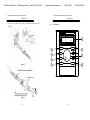
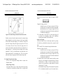
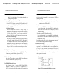
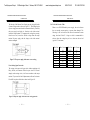
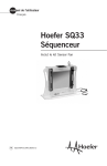
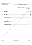
Test Equipment Depot 99 Washington Street Melrose, MA 02176-6024 PSH SERIES PROGRAMMABLE POWER SUPPLY www.testequipmentdepot.com 800-517-8431 781-665-0780 FAX PSH SERIES PROGRAMMABLE POWER SUPPLY USER MANUAL USER MANUAL SAFETY TERMS AND SYMBOLS FOR UNITED KINGDOM ONLY These terms may appear in this manual or on the product: NOTE: This lead/appliance must only be wired by competent persons WARNING. Warning statements identify condition or WARNING: THIS APPLIANCE MUST BE EARTHED practices that could result in injury or loss of life. IMPORTANT: The wires in this lead are coloured in accordance with the following code: CAUTION. Caution statements identify conditions or practices that could result in damage to this product or other property. Green/ Yellow: Blue: Brown: Earth Neutral Live (Phase) The following symbols may appear in this manual or on the product: As the colours of the wires in main leads may not correspond with the colours marking identified in your plug/appliance, proceed as follows: The wire which is coloured Green & Yellow must be connected to the Earth terminal marked with the letter E or by the earth symbol DANGER ATTENTION Protective Earth (ground) Frame or Chassis or coloured Green or Green & Yellow. High Voltage refer to Manual Conductor Terminal The wire which is coloured Blue must be connected to the terminal which is marked with the letter N or coloured Blue or Black. Terminal Terminal The wire which is coloured Brown must be connected to the terminal marked with the letter L or P or coloured Brown or Red. If in doubt, consult the instructions provided with the equipment or contact the supplier. ii iii Test Equipment Depot 99 Washington Street Melrose, MA 02176-6024 PSH SERIES PROGRAMMABLE POWER SUPPLY www.testequipmentdepot.com 800-517-8431 781-665-0780 FAX PSH SERIES PROGRAMMABLE POWER SUPPLY USER MANUAL USER MANUAL This cable/appliance should be protected by a suitably rated and approved HBC mains fuse: refer to the rating information on the equipment and/or user instructions for details. As a guide, cable of 0.75mm2 should be protected by a 3A or 5A fuse. Larger conductors would normally require 13A types, depending on the connection method used. 1. PRODUCT INTRODUCTION Any moulded mains connector that requires removal /replacement must be destroyed by removal of any fuse & fuse carrier and disposed of immediately, as a plug with bared wires is hazardous if a engaged in live socket. Any re-wiring must be carried out in accordance with the information detailed on this label. auto-testing and auto-control. The series of products have improved 1-1. Description PSH -series Programmable Power Supply is controlled by Micro Processor Unit (MPU) that can easily connect communication interface R S-232 or GPIB to computer in order to satisfy user’s demands for greatly the shortage of the tradit ional big size, heavy weight products. The voltage and current are completely controlled by 12 bits D/A Converter with higher resolution and accuracy. Also, the digitalization of system makes a speedy, precise and convenient input of information controlled by the keyboard and rotation knobs. The adjustment of voltage/current is made by software calibration without manual error that will increase the preciseness of the instrument. The function of Over Voltage Protection (OVP) and Over Current Protection (OCP) is set with software and detected with hardware to achieve protected function precisely and speedily in order to prevent users from danger by using the instrument. 1-2. Features 1) Wide Input Voltage Range and High Power Factor (P.F). 2) High Efficient. 3) Constant Voltage and Constant Current Operation. 4) The protection for Over Voltage, Over Current and Over Heat. iv 1 Test Equipment Depot 99 Washington Street Melrose, MA 02176-6024 www.testequipmentdepot.com PSH SERIES PROGRAMMABLE POWER SUPPLY 800-517-8431 PSH SERIES PROGRAMMABLE POWER SUPPLY USER MANUAL 5) Screw the AC input cover to the AC terminal on the rear panel tightly. USER MANUAL l Front Panel R PROGRAMMABLE POWER SUPPLY RMT ADRS 10. 10V CV OCP PSH-1036 OUT 36. 10 A 8 MENU 2 7 F C 3 6 Figure 1 1 POWER LOCAL 5 VSET ISET OUTPUT ENTER 4 Cable Gland(with Strain Relief) AC Input Cover Figure 2 10 781-665-0780 FAX 11 Test Equipment Depot 99 Washington Street Melrose, MA 02176-6024 PSH SERIES PROGRAMMABLE POWER SUPPLY www.testequipmentdepot.com 800-517-8431 781-665-0780 FAX PSH SERIES PROGRAMMABLE POWER SUPPLY USER MANUAL USER MANUAL knob. Now, use the [F/C] key to input the integral or dismal number. Figure 5-1 Constant Voltage/Constant Current Characteristic Similarly, crossover from the constant current to the constant voltage mode automatically occurs from a decrease in load, a good example of this would be seen when chargi ng a 12 volt battery. Initially, the open circuit voltage of the power supply may be preset for 13.8 volts. A low battery will place a heavy load on the supply and it will operate in the constant current mode, which may be adjusted for a 1 amp charging rate. As the battery becomes charged, and its voltage approaches 13.8 volts, its load decreases to the point where it no longer demands the full 1 amp charging rate. This is the crossover point where the power supply goes into the constant voltage mode. 5-2. Output Voltage/Current Setting At first, set to voltage/current setting window or output value displayed window: --Output Voltage Setting: Switch the flashed cursor to voltage input position by pressing [Vset/Iset] key, and modify the setting value by using the wheel 14 Example: Set voltage at 20.00V. Switch the cursor to mV range by using the [F/C] key and adjust the value to number 00 with the rotation knob, then switch the cursor to V range by using the [F/C] key and adjust the value to number 20 with the rotation knob to complete the modification. PS. At the moment, if the OUTPUT is on, the output voltage will be output the corresponding voltage value immediately following the adjustment of the rotation knob. --Output Current Setting: Switch the flashed cursor to current input position by pressing [Vset/Iset] key, and modify the setting value by using the wheel knob. Now, use the [F/C] key to input the integral or dismal number. Exa mple: Set voltage at 18.00A. Switch the cursor to mA range by using the [F/C] key and adjust the value to number 00 with the rotation knob, then switch the cursor to A range by using the [F/C] key and adjust the value to number 18 with the rotation knob to complete the modification. PS. When the load current of output terminal exceeds the current setting value, the instrument is operated under the Constant Current mode (C.C. Mode), if it doesn’t exceed the current setting value, the instrument is operated under the Constant Voltage mode (C.V. Mode). If the maximum output voltage of the instrument is larger than 36V, the minimum adjustable step of the rotation knob is 15 Test Equipment Depot 99 Washington Street Melrose, MA 02176-6024 PSH SERIES PROGRAMMABLE POWER SUPPLY USER MANUAL 20mV, if it is smaller than 36V, the minimum adjustable step of the rotation knob is 10mV. 5-3.Over Voltage /Current Protection Setting --Over Voltage Protection Setting: Set to OVP SET window by pressing [MENU], modify the OVP setting value with [F/C] key to input integral or dismal number, then press [ENTER]. --OVP Status Clear Up: When the output voltage exceeds the setting voltage, the instrument will stop output and get into OVP mode by displaying “OVP Error. Press “LOCAL” to reset” messages on the panel. Now press [LOCAL] to clear OVP status, back to previous status. --Over Current Protecti on Setting: Set to OCP SET window by pressing [MENU], then switch OCP to ON or OFF with the knob and press [ENTER]. When the OCP is on, the output current equals or exceeds the setting current, the instrument will stop output and get into OCP mode by displaying “OCP Error. Press “LOCAL” to reset” messages on the panel, Now press [LOCAL] to clear OCP status, back to previous status. 5-4. Display Contrast Setting: Set to Contrast Setting window by pressing [MENU], modify the Contrast setting value with knob, then press [ENTER]. www.testequipmentdepot.com 800-517-8431 781-665-0780 FAX PSH SERIES PROGRAMMABLE POWER SUPPLY USER MANUAL using the wheel knob to modify the value and press [ENTER] to complete the setting. Note: The system will detect the interface used at present automatically, and switch the detected interface over the setting interface of GPIB or RS-232. Example: 1) If want to set the GPIB address value to 08: Set to interface window by pressing [MENU], and adjust the address value to 08 with the wheel knob and p ress [ENTER] to complete the setting. 2) If want to set the RS-232 Baud Rate to 9600: Set to interface window by pressing [MENU], and adjust the Baud Rate value to 9600 with the wheel knob and press [ENTER] to complete the setting. For further details, please refer to the programmer manual of PST/PSS/PSH series programmable power supply. 5-7. Remote Error Sensing A normal power supply can perform its best load regulation, line regulation, low output impedance, and low output ripple and noise, as well as the rapidly transient recovery response. Please refer to figure 5-2. If there is any test lead connected between load and output terminal, the best characters of power supply can not be shown up on the load terminal. 5-5. Buzzer Setting Set to Buzzer Set window by pressing [MENU], switch Buzzer to ON or OFF with the knob, then press [ENTER]. 5-6. GPIB/RS232 Interface Setting Set to Interface window by pressing [MENU]. If the GPIB is displayed, the Address value window will be appeared, if the RS-232 is displayed, the Baud Rate window will be appeared, then 16 Figure 5-2 The power supply with local error sensing 17 Test Equipment Depot 99 Washington Street Melrose, MA 02176-6024 PSH SERIES PROGRAMMABLE POWER SUPPLY www.testequipmentdepot.com 800-517-8431 PSH SERIES PROGRAMMABLE POWER SUPPLY USER MANUAL The function of the Remote Error Sensing can only be applied to the Constant Voltage mode as shown in Figure 5-3. The feedback point of power supply must start from the load terminal directly. Therefore, the power supply can display its function on the load terminal instead of output terminal. To compensate the voltage drop causing from the test lead, it needs to shift the voltage from the output terminal of power supply, and the voltage on the load terminal remains unchanged. Figure 5-3 The power supply with remote error sensing Error Sensing Open Protection The sensing circuit must avoid open circuit without equipping with Relay, Switch, and Connector. When the open circuit is occurred USER MANUAL 5-8. Test Lead Selective Table When we use PSH -SER models power supply, the test lead must have an enough current capacity to prevent from damaged. The following is test lead selective table shows the maximum current rating, based on 450A/cm2. A large test lead is recommended in order to reduce the voltage drop as less as better on the test lead (typical 0.5V maximum). Wire Size (AWG) 20 18 16 14 12 10 8 Max. Current (A) 2.5 4 6 10 16 21 36 Wire Size (AWG) 6 4 2 1 1/0 2/0 abruptly on the sensing circuit, it will cause overshoot on the output terminal. To prevent this kind of phenomenon, add small resistance R1 and R2 or replace with diode as shown in the Figure 5-4. Figure 5-4 The power supply with remote error sensing protection 18 781-665-0780 FAX 19 Max. Current (A) 61 97 155 192 247 303 Test Equipment Depot 99 Washington Street PSH SERIES PROGRAMMABLE POWER SUPPLY Melrose, MA 02176-6024 www.testequipmentdepot.com 800-517-8431 PSH SERIES PROGRAMMABLE POWER SUPPLY USER MANUAL At first, set the DMM to 200V voltage range. 781-665-0780 FAX USER MANUAL [Step 2.1] Get into the window of Calibration item, select the item of Voltage calibration with knob and press [ENTER]. [Step 2.2] Input measured voltage value (Min) with the knob and press [ENTER]. During the value input, use [F/C] key to switch over the integral or dismal number input. [Step 2.3] Now, adjust VR301 properly for the measured voltage (Max) of DMM according to the value displayed in the window, then press [ENTER]. Note: During the adjustment, the maximum distortion range of the measured value is at 0.005V. [Step 3] Current Calibration Steps At first, make sure the output is disconnected with test leads, if the specification of current is smaller than 20A, can either use 20A range of GDM -8145G or connect current shunt to output terminal to measure the output current. If the specification of curr ent is larger than 20A, must connect current shunt to output terminal to measure both ends of the current shunt with 200mV range of DMM. [Step 3.1] Get into the window of Calibration item, select the item of current calibration with knob and press [ENTER] to start Current Calibration Steps. [Step 3.2] Input measured voltage value (Max) with the knob and press 22 23 Test Equipment Depot 99 Washington Street Melrose, MA 02176-6024 PSH SERIES PROGRAMMABLE POWER SUPPLY USER MANUAL 7-2. The Configuration of PSH-series Block System The whole Block system consists of the foll owing Circuit Blocks: Power Factor Corrector: BD101, Q101-Q103, D102. Micro Processor Unit (MPU): U308 Digital to Analog Converter (DAC): U316. Analog Switch Circuit: U328, R356, R363, R370, C314, C318, C320, U331. Pulse Width Modulation: U206. Driver C ircuit: Q202 -Q203, T202. Power Stage: Q204 -Q205, Q211-Q212, T203, D207 -D208, L201, C246-C249, C253. Post Regulator: Q207, Q208. Voltage Control Circuit: U334. Current Control Circuit: U334. Error Amplifier: U333. Opto-isolator: U209. Auxiliary Power supply : Q201, U203, T201. OVP: U315, U331, Q209, U327, Q310, U328. Unit 2: When the power reaches about 2 times the Unit 1, the Unit 2 will be used additionally. Unit 3: When the power reaches about 3 times the Unit 1, the Unit 2 and Unit 3 will be used additio nally. 26 www.testequipmentdepot.com 800-517-8431 781-665-0780 FAX