1
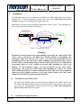
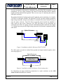
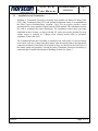
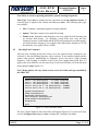
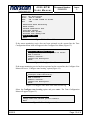
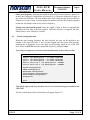
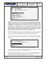
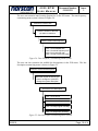
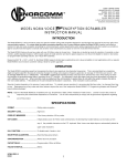
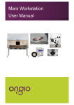
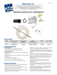
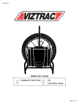
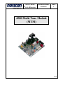
4200 MTM
USER MANUAL
Document Number:
D00802R01
Issue:
3
4200 Multi Tone Module
(MTM)
99058
4200 MTM
USER MANUAL
Document Number:
D00802R01
Issue:
3
TABLE OF CONTENTS
1.
INTRODUCTION..............................................................................................................................................1
1.1
1.2
2.
THEORY OF OPERATION.............................................................................................................................2
2.1
2.2
3.
INSTALLATION AT THE CENTRAL OFFICE ....................................................................................................4
INSTALLATION AT A SPLICE ENCLOSURE .....................................................................................................4
INSTALLATION AT THE TERMINATION .........................................................................................................6
CONFIGURING THE MULTI TONE MODULE .........................................................................................9
4.1
4.2
5.
CABLE LOCATING USING THE MULTI TONE MODULE ..................................................................................2
LINE TERMINATION UNITS (LTU) ...............................................................................................................2
INSTALLATION ...............................................................................................................................................4
3.1
3.2
3.3
4.
STANDARD FEATURES .................................................................................................................................1
SPECIFICATIONS ..........................................................................................................................................1
TONE FREQUENCY PRESETS ........................................................................................................................9
SELECTING TONE FREQUENCY ..................................................................................................................11
MULTI TONE MODULE OPERATION......................................................................................................16
5.1
5.2
5.3
TONE LOCATING OPERATION ....................................................................................................................13
KEYPAD TONE CONTROL ..........................................................................................................................16
MTM CONFIGURATION USING IVR ..........................................................................................................17
CONTACT INFORMATION ..................................................................................................................................20
06/2010
Page: i
4200 MTM
USER MANUAL
Document Number:
D00802R01
Issue:
3
List of Figures:
Figure 1: Typical Application - Single Armor Fiber Cable ................................................................... 2
Figure 2: Installation “Zones” .............................................................................................................. 4
Figure 3: Installation at Splice Enclosure With 2745 SGU ................................................................... 5
Figure 4: Installation at Splice Enclosure (Tone locating only)............................................................ 5
Figure 5: Termination Protection Assembly at Building Entry ............................................................. 7
Figure 6: Termination Installation in Splice Enclosure with LTU ........................................................ 8
Figure 7: 4200 CMS Main Menu ........................................................................................................... 9
Figure 8: Frequency Config Menu....................................................................................................... 10
Figure 9: Tone Selection Menu ............................................................................................................ 10
Figure 10: Custom Tone....................................................................................................................... 10
Figure 11: 4200 CMS Main Menu ....................................................................................................... 11
Figure 12: Line Control Menu ............................................................................................................. 12
Figure 13: Configure Line Menu ......................................................................................................... 12
Figure 14: Configure Line Menu with armor monitoring.................................................................... 12
Figure 15: Tone Configuration Menu .................................................................................................. 12
Figure 16: 4200 CMS Main Menu ....................................................................................................... 13
Figure 17: Line Control Menu ............................................................................................................. 14
Figure 18: Line Control Menu for OSP Line With Locating Tone ...................................................... 14
Figure 19: Tone Control Menu ............................................................................................................ 16
Figure 20: Tone Frequency Menu........................................................................................................ 16
Figure 21: Line Menu........................................................................................................................... 16
Figure 22: Line Status Screen With Tone Applied ............................................................................... 17
Figure 23: IVR Menu System ............................................................................................................... 18
Figure 24: Tone Frequency Customizing Menu System....................................................................... 19
Figure 25: Line Description Customizing Menu System...................................................................... 19
06/2010
Page: ii
4200 MTM
USER MANUAL
1.
Document Number:
D00802R01
Issue:
3
Introduction
The 4200 Multi Tone Module (MTM) is a full-featured tone generating system. It can
provide a wide range of tone frequencies to continuous outside plant cable installations,
when below grade cable locating is required. The 4200 MTM module is designed for use in
offices where tone cable locating capabilities for one to four cable routes of up to 60 miles
or 100 kilometers each is required (actual distances can vary depending on cable
armor/sheath condition). Operating over any metallic circuit such as metal armor, trace
wire or twisted copper pair the 4200 MTM module will generate frequencies to match your
hand held receiver units.
1.1
Standard Features
• Can generate user specified frequencies 5 Hz to 10k Hz on North American version.
• Can generate user specified frequencies 5 Hz to 1k Hz on UK and European version.
• Easy access front control panel for MTM operation
1.2
Specifications
Multi Tone Module (MTM) North American version
Freq. Range
Max. power out
Max. voltage out
Short cct. Dur.
5 Hz to 10k Hz
50
W
100
V rms
Indefinite
Multi Tone Module (MTM) UK and European version
Freq. Range
Max. power out
Max. voltage out
Short cct. Dur.
06/2010
5 to 1000 Hz
40
W
50
V rms
Indefinite
Page: 1 of 20
4200 MTM
USER MANUAL
2.
Document Number:
D00802R01
Issue:
3
Theory of Operation
2.1
Cable locating using the Multi Tone Module
The Multi Tone Module (MTM) adds cable-locating functionality to the 4200 CMS.
Located in the 4200 CMS chassis as an option module, it provides long distance cable
toning for locating buried and underground cables. The tone-tracing signal can be
activated by a front panel keypad on the 4200 CMS, by telephone using touch-tone
commands or by computer using dial up modem access with terminal communication
software such as Norcomm™ or Telnet with Telnet software such as Tera Term.
The user can select any one of the four cable line outputs and pre-program up to four tone
frequencies. Continuous ranges of frequencies are available from 5 Hz to 10k Hz (North
American version) or 5 Hz to 1000 Hz (UK & European version). This allows the use of
a variety of portable receivers from various manufacturers. The projected range for the
tone signal before serious signal attenuation is approximately 60 miles or 100 kilometers
on a continuous cable that is terminated with a Line Termination Unit (LTU) (Figure 1).
Actual distances will vary depending on cable armor/sheath condition.
Note: Only one frequency can be activated simultaneously on more than one line.
42 00 CMS Te r m i na l
42 00 C MS
LTU
MTM
Tone
GN D
Ar m o r or
Sh ie ld
Figure 1: Typical Application - Single Armor Fiber Cable
2.2
Line Termination Units (LTU)
LTUs provide the required termination impedance for cable locator tones. There are two
types of LTUs that can be installed at the termination points along with the monitoring
termination sensor(s).
2316 – 0K LTU: This type is used to terminate a single ended cable network topology
with no branches. They are designed to draw the tone frequency down the single ended
armored line to achieve optimum signal strength at the termination end.
06/2010
Page: 2 of 20
4200 MTM
USER MANUAL
Document Number:
D00802R01
Issue:
3
Note: If the single ended network is less than 20 miles or 32 kilometers from the
transmitter source, installing a 2316 – FC LTU is recommended. This will stop the tone
frequency transmitter from going into an overload state because of the low load line
impedance of the short cable line.
2316 – FC LTU: This type is used to terminate each branch of a multiple branch cable
network topology. They are designed to dissipate the tone frequency as evenly as
possible throughout the entire branch network and to each termination point.
06/2010
Page: 3 of 20
4200 MTM
USER MANUAL
3.
Document Number:
D00802R01
Issue:
3
Installation
The following instructions will explain the installation of a 4200 system that is used for tone
locating only. If armor monitoring is being used, refer to the 4200 Alarm Circuit Unit
(ACU) user manual for installation and connection details.
Installation of the tone locating equipment takes place in three “zones”. The transmitter site,
splice points, and the termination site (Figure 2).
CO / Gateway / ILA
Office Equipment
4200 CMS
Splice Enclosure
4200 CMS
CABLE MANAGEMENT SYSTEM
CO / Gateway / ILA
LTU Termination
Splice Tray
LTU
Cable
Armor
Figure 2: Installation “Zones”
Warning!
Potential for electrical shock exists when handling cables while the Alarm Circuit Unit
(ACU) card is activated or the Multi Tone Module (MTM) is transmitting tone
frequencies. Make sure that the ACU card is set to OFF and that the MTM is not
transmitting tone on the cable that is being handling at that particular time. Always
take DC and AC measurements using a Norscan 1303 System Test Set or a Multi-meter
to determine what AC or DC voltages are present before handling the cable. Note:
Induced AC and transient voltages can also be present on the cable armor.
Temporarily hard ground the cable armor before handling the cable in the central
office, outside plant splice or remote termination location. Once the work is completed,
remove the hard ground connection to the cable armor. Remove the cable armor
connection first and then the local ground connection.
3.1
Installation at the Central Office
The Multi Tone Module will come preinstalled and calibrated in a 4200 CMS chassis.
The 4200 CMS with an MTM needs to be installed at the central office to transmit the
tone signal. For CMS installation details please refer to the 4200 Cable Management
System (CMS) with AUIC user manual.
3.2
06/2010
Installation at a Splice Enclosure
Page: 4 of 20
4200 MTM
USER MANUAL
Document Number:
D00802R01
Issue:
3
For tone locating the cable must be continuous from the 4200 CMS (transmitter) to the
termination. At every splice enclosure the armors in both directions must be bonded
together and disconnected from ground. There are two ways of connecting the armors at
each splice enclosure.
The preferred method of setting up the outside plant for armor monitoring is to install a
2745 SGU at each splice location. The Norscan 2745 SGU provides a path to ground for
high voltage transients, and gives the ability to sectionalize the armor without having to
enter the splice enclosure. The 2745 SGU is typically placed outside the manhole or
cable vault for easy access. With the 2745 SGU the armors in two directions are
connected to the SGU via 6-gauge solid wire and bonded together inside the unit (Figure
3). A failsafe gas tube provides high voltage protection for personnel, equipment and the
cable itself.
Splice Enclosure
West / South Armor
East / North Armor
2745
SGU
Quick
Disconnects
Figure 3: Installation at Splice Enclosure With 2745 SGU
The cable armors can also be isolated from ground and simply bonded together with a
wire strap (Figure 4).
Splice Enclosure
West / South Armor
East / North Armor
Splice Tray
Figure 4: Installation at Splice Enclosure (Tone locating only)
For information on armor monitoring connections in a splice enclosure see the 4200
Alarm Circuit Unit (ACU) user manual.
06/2010
Page: 5 of 20
4200 MTM
USER MANUAL
3.3
Document Number:
D00802R01
Issue:
3
Installation at the Termination
Installing a Termination Protection Assembly that includes an Induced Voltage Filter
(IVF), Line Termination Unit (LTU) and optional termination sensor is recommended at
the Cable Vault or Building Entry Location. The LTUs are used to provide a return
ground path for a tone-generated signal from the MTM module. The termination sensors
are used to terminate the armor monitoring. The termination sensors have gas tubes
embedded in their circuitry, so along with the IVF units, prevent the potential for stray
voltage surges or induced AC voltages from causing serious harm to personnel,
equipment, or the cable itself.
The Termination Protection Assembly is mounted to the wall surface in close proximity
to the cable vault area. Connect the cable armors from the outside plant to the appropriate
connection terminals (East/North, West/South) as they are labeled on the front cover of
the double ended unit assembly. Ground the entire Transmitter Protection Assembly by
connecting the Ground/Earth terminal to Building Ground. See Figure 5.
06/2010
Page: 6 of 20
4200 MTM
USER MANUAL
Document Number:
D00802R01
Issue:
3
Note: STU termination sensors are only required if cable armor monitoring is utilized.
The 51300 is available for single ended armor terminations (one IVF, STU and LTU).
Model 51300 - TERMINATION PROTECTION ASSEMBLY
2303 IVF (60 Hz)
or
2313 IVF (50 Hz)
EAST/NORTH
ARMOR
GROUND/
EARTH
2316 LTU
FC or 0K
BLUE
2230 STU
WHITE
WHITE
2230 STU
2316 LTU
FC or 0K
BLUE
2303 IVF (60 Hz)
or
2313 IVF (50 Hz)
WEST/SOUTH
ARMOR
Label P/N 50130
Figure 5: Termination Protection Assembly at Building Entry
06/2010
Page: 7 of 20
4200 MTM
USER MANUAL
Document Number:
D00802R01
Issue:
3
If the cable or cable branch terminates inside a splice enclosure, the termination
equipment must be installed at the splice where the cable ends. The following diagram
illustrates the proper way of connecting a Line Termination Unit (LTU) used in
conjunction with the MTM and a termination sensor for armor monitoring in a splice
enclosure (Figure 6). Below grade LTUs are also available for installation outside the
splice enclosure.
Note: The termination sensor is only required if armor monitoring is being used.
Proper placement of the LTU and STU devices are essential when installed in a splice
enclosure, make sure that these devices are not installed on the fiber tray(s) directly.
Splice Enclosure
LTU
Armor being
terminated
22ga MDT Leads
Blue
STU
White
Moisture Detection
Tape (MDT)
Figure 6: Termination Installation in Splice Enclosure with LTU
06/2010
Page: 8 of 20
4200 MTM
USER MANUAL
4.
Document Number:
D00802R01
Issue:
3
Operating the Multi Tone Module
This section will explain the configuration and operation of a 4200 MTM with an AUIC. If
armor monitoring is being used, refer to the 4200 Alarm Circuit Unit (ACU) user manual for
armor monitoring configuration details.
Connect to the 4200 CMS via serial, modem or Telnet connection and login using
administrator or diagnostic access. For connection and login details see the 4200 Cable
Management System (CMS) with AUIC user manual.
4.1
Tone Frequency Presets
The Tone Frequency Configuration Menu allows the user to set four standard locating
tone frequencies (Administrator or Diagnostic login only). Each of the tones can be
configured for a specific frequency to match your hand held receiver(s). The MTM
module can also be pre-programmed to generate a Dual Sine Waveform for fault locating
with an A-Frame device.
To configure the Multi Tone Module use the arrow keys to select Tone Frequency
Configuration from the 4200 CMS main menu (Figure 7) and press enter.
Note: Menu options will vary based on user access level and card types installed in the
4200 CMS.
Line
Line
Line
Line
Line
Line
1.
2.
3.
4.
11
12
Main Menu
<no description> - no cards connected
<no description> - no cards connected
<no description> - no cards connected
<no description> - no cards connected
Slot 6 Ch 1. <no description> - FODARK
Slot 6 Ch 2. <no description> - FODARK
System Configuration
Comms Configuration
Date/Time Configuration
-> Tone Frequency Configuration
Alarm Target Configuration
Diagnostics
Quit
Figure 7: 4200 CMS Main Menu
The Frequency Config Menu will appear showing the four preset locating tone
frequencies (Figure 8).
06/2010
Page: 9 of 20
4200 MTM
USER MANUAL
Document Number:
D00802R01
Issue:
3
Frequency Config Menu
-> 1. 577Hz
2. 512Hz
3. 9820Hz
4. 10/20Hz
Back
Figure 8: Frequency Config Menu
To make a change to one of the four preset tones, use the arrow keys to select the tone
preset and press enter. The Tone Selection Menu will appear (Figure 9).
Tone Selection Menu
-> 273 Hz
340 Hz
400 Hz
440 Hz
460 Hz
512 Hz
560 Hz
577 Hz
982 Hz
10 Hz (dual sine)
Custom…
Back
Figure 9: Tone Selection Menu
Use the arrow keys to select a preprogrammed tone or select Custom to program a
custom tone and press enter. If custom is selected, the Custom Tone dialog box will
appear (Figure 10).
Custom Tone
1. Tone Description
2. Tone Frequency
3. Tone Type
<OK>
____________
0_____
sine___
<CANCEL>
Enter Custom Tone Parameters
Figure 10: Custom Tone
The Custom Tone dialog box allows the user to specify the tone description, frequency
and type of tone. Use the arrow keys to select the menu items.
Tone Description: Enter the description for the custom tone and press enter. The
description will be used to identify the tone on the AUIC menus.
Tone Frequency: Enter the frequency of the custom tone (5Hz – 10000Hz for North
America or 5Hz – 1000Hz for Europe) and press enter. The frequency of the tone
produced by the MTM inside the 4200 CMS must match the frequency of the tone
detected by the locating receiver.
06/2010
Page: 10 of 20
4200 MTM
USER MANUAL
Document Number:
D00802R01
Issue:
3
Note: Refer to receiver operating manual for specific locating frequencies.
Tone Type: Press enter to change the tone type then use the up and down arrows to
select the type of signal for the custom tone and press enter. The following tone types
are available:
4.2
•
Sine: Transmits a sinusoidal signal for locating (default).
•
Square: Transmits a square wave signal for locating.
•
Fault Locate: Transmits a dual frequency sine wave signal for fault locating with
an A-frame fault locator. To configure a fault locate tone, enter the base
frequency between 5 and 500Hz and the MTM will generate the second frequency
two times the base frequency. For example if the entered base frequency is 10 Hz
the dual sine wave signal will be 10/20Hz.
Selecting Tone Frequency
After the tone locating presets have been set to the required locate frequencies (see
section 4.1), the tone locating frequency can be selected. A user who has logged onto the
system with operator, administrator or diagnostic access can select a tone locating
frequency. Tone locating is available on any of the four outside plant (OSP) lines. To
apply a tone to an OSP line, use the arrow keys to select an OSP line (1-4) from the main
menu and press enter (Figure 11).
Note: Menu options will vary based on user access level and card types installed in
the 4200 CMS.
-> Line
Line
Line
Line
Line
Line
1.
2.
3.
4.
11
12
Main Menu
<no description> - no cards connected
<no description> - no cards connected
<no description> - no cards connected
<no description> - no cards connected
Slot 6 Ch 1. <no description> - FODARK
Slot 6 Ch 2. <no description> - FODARK
System Configuration
Comms Configuration
Date/Time Configuration
Tone Frequency Configuration
Alarm Target Configuration
Diagnostics
Quit
Figure 11: 4200 CMS Main Menu
The Line Control Menu for the selected line will appear (Figure 12). Use the arrow keys
to select Configure line and press enter to display the Configure Line Menu.
06/2010
Page: 11 of 20
4200 MTM
USER MANUAL
Line 1:
Sensor
Armor
Tone
Document Number:
D00802R01
Issue:
3
Line Control Menu
<no description>
:STU no alarms
:ON –0.00mA >150kR no alarms
:OFF
Deactivate armor monitoring
Reset alarms
Perform termination test
View test results
Activate tone (577Hz)
Activate tone safety lock
-> Configure line...
Back
Figure 12: Line Control Menu
If the armor monitoring service has not been activated on the current line the Tone
Configuration Menu items will appear in the Configure Line Menu (Figure 13).
Configure Line Menu
-> Select tone frequency <577Hz>
Change tone auto-shutoff period <10 hours>
Add a service...
Remove a service...
Change line description
Back
Figure 13: Configure Line Menu
If the armor monitoring service has been activated on the current line, the Configure Line
Menu will have a “Configure tone locating” option (Figure 14).
Configure Line Menu
Configure armor monitoring...
-> Configure tone locating...
Add a service...
Remove a service...
Change line description...
Back
Figure 14: Configure Line Menu with armor monitoring
Select the Configure tone locating option and press enter. The Tone Configuration
Menu will appear (Figure 15).
Tone Configuration Menu
->Select tone frequency <577Hz>
Change tone auto-shutoff period <10hours>
Back
Figure 15: Tone Configuration Menu
06/2010
Page: 12 of 20
4200 MTM
USER MANUAL
Document Number:
D00802R01
Issue:
3
Select tone frequency: Selecting this option displays the four tone frequency presets set
in the Tone Frequency Configuration (see section 4.1). Choose the frequency to apply to
any of the four OSP lines. The tone module in the 4200 CMS can only generate one tone
frequency at a time, if tone is already applied to another OSP line, the frequency applied
to that line will change to the newly selected frequency.
Change tone auto-shutoff period: Enter the length of time in hours to automatically
deactivate the tone after it has been applied. Each time the tone is reapplied, the autoshutoff timer is reset. Default is 10 hours.
4.3
Tone Locating Operation
When the tone locating frequency has been selected, the tone can be applied to any
number of the four OSP lines. A user who has logged onto the system with operator,
administrator or diagnostic access can apply a tone locating signal to any of the OPS
lines. Select an OSP line from the main menu (Figure 16) and press enter.
Note: Only one frequency can be activated simultaneously on more than one line.
-> Line
Line
Line
Line
Line
Line
1.
2.
3.
4.
11
12
Main Menu
<no description> - no cards connected
<no description> - no cards connected
<no description> - no cards connected
<no description> - no cards connected
Slot 6 Ch 1. <no description> - FODARK
Slot 6 Ch 2. <no description> - FODARK
System Configuration
Comms Configuration
Date/Time Configuration
Tone Frequency Configuration
Alarm Target Configuration
Diagnostics
Quit
Figure 16: 4200 CMS Main Menu
Note: Menu options will vary based on user access level and card types installed in the
4200 CMS.
The line control menu for the selected line will appear (Figure 17).
06/2010
Page: 13 of 20
4200 MTM
USER MANUAL
Line 1:
Sensor
Armor
Tone
Document Number:
D00802R01
Issue:
3
Line Control Menu
<no description>
:STU no alarms
:ON –0.00mA >150kR no alarms
:OFF
->Deactivate armor monitoring
Reset alarms
Perform termination test
View test results
Activate tone (577Hz)
Activate tone safety lock
Configure line...
Back
Figure 17: Line Control Menu
WARNING! Potential for electrical shock exists when handling cables while the
Alarm Circuit Unit (ACU) card is activated or the Multi Tone Module (MTM) is
transmitting tone frequencies. Make sure that the ACU card is set to OFF and that
the MTM is not transmitting tone on the cable that you are handling at that
particular time. Always take DC and AC measurements using a Norscan 1303
System Test Set or a Multimeter to determine what AC or DC voltages are present
before handling the cable. Induced AC voltages can be present on the cable armor
when the cable is installed in close proximity to electrical power lines.
Activate tone: Select this item from the menu to apply the locating tone to the current
line. A tone with the indicated frequency will be applied to the current OSP line. To
change the tone frequency on all lines see section 4.2 Selecting Tone Frequency.
When a locating tone is applied to the OSP line, armor monitoring is halted and the
current state of the locating tone is shown in the top section of the line control menu
(Figure 18).
Line Control Menu
Line 1: <no description>
Tone
:ON 577.00Hz 615.45mA 67.35V
->Deactivate tone (577Hz)
Activate tone safety lock
Configure line...
Back
Figure 18: Line Control Menu for OSP Line With Locating Tone
When cable locating is complete select Deactivate tone and press enter, the locating
tone will be deactivated and armor monitoring will resume.
Repeat this procedure to apply tone to any or all of the four OSP lines. Applying tone to
more than one line will share the tone output power between the multiple lines. For
maximum locate signal strength only apply tone to one line at a time.
06/2010
Page: 14 of 20
4200 MTM
USER MANUAL
Document Number:
D00802R01
Issue:
3
Activate tone safety lock: This option will toggle the tone safety lock. When the tone
safety lock is activated, the locating tone cannot be applied to any OSP lines. This
prevents the tone from being applied remotely while cable maintenance is in progress.
06/2010
Page: 15 of 20
4200 MTM
USER MANUAL
5.
Document Number:
D00802R01
Issue:
3
Keypad and IVR Operation
5.1
Keypad Tone Control
The front panel of the 4200 CMS with AUIC can be used to select the OSP line for the
tone, the tone frequency, and to activate or deactivate the tone.
Press the MENU button on the front panel of the 4200 CMS. The Tone Control Menu
will appear (Figure 19).
-> 577Hz
Lines: 1:Off 2:Off 3:Off 4: Off
Turn on Safety Lockout
Done
Figure 19: Tone Control Menu
The first item on the Tone Control Menu shows the selected tone frequency. To change
the selected tone frequency, move the arrow to the first item using the arrow keys and
press OK. The Tone Frequency menu will appear (Figure 20). Select the required tone
frequency and press OK. To go back without changing the tone frequency, scroll down,
select Back then press OK.
-> 1.
2.
3.
4.
577Hz
512Hz
9280
10/20
Figure 20: Tone Frequency Menu
The second item on the Tone Control Menu shows the OSP lines that have tone applied.
To add or remove tone from an OSP line, move the arrow to the second item using the
arrow keys and press OK. The Line Menu will appear (Figure 21). Select the OSP line
to add or remove tone and press OK. An asterisk indicates which OSP lines that have
tone applied. When OSP line selection is complete, scroll down, choose Done then press
OK. The Tone Control Menu will appear and show which lines have tone applied.
->
Line
Line
* Line
Line
1:
2:
3:
4:
<no
<no
<no
<no
description>
description>
description>
description>
Figure 21: Line Menu
Repeat this procedure to apply tone to any or all of the four OSP lines. Applying tone to
more than one line will share the tone output power between the multiple lines. For
maximum locate signal strength only apply tone to one line at a time.
06/2010
Page: 16 of 20
4200 MTM
USER MANUAL
Document Number:
D00802R01
Issue:
3
The third item on the Tone Control Menu will activate the safety lockout. To enable the
safety lockout, move the arrow to the third item using the arrow keys and press OK.
While the safety lockout is enabled, the tone cannot be turned on. To disable the safety
lockout, press Menu. A message will be displayed to confirm that the safety lockout will
be disabled. Answer Yes or No then press OK.
When the tone configuration is complete, select Done from the Tone Control Menu and
press OK. The display will return to the Main AUIC screen.
If tone has been applied, the Main AUIC screen will show the status of the MTM (Figure
22).
Line 2 : (no description)
Tone
:ON 512.00Hz 278.45mA
64.28V
Figure 22: Line Status Screen With Tone Applied
5.2
MTM Configuration Using IVR
Interactive Voice Response (IVR) allows the user to access and manipulate the MTM
settings via a touch-tone telephone hand set. The 4200 MTM is preprogrammed with
factory default voice prompts but can be customized using the telephone.
The flow chart in Figure 23 gives an overview on how to configure the 4200 MTM using
IVR.
06/2010
Page: 17 of 20
4200 MTM
USER MANUAL
Phone 4200 CMS
The unit will answer after the first ring.
You are prompted to enter a password.
Document Number:
D00802R01
Issue:
3
Using a touch tone phone,
enter the IVR password using
the phone keypad.
"577Hz tone is ON line 1"
The 4200 CMS will then respond
with the actual state of the MTM
module.
Press 1 to select different tone.
(Main Menu Option)
Select from the
Main Menu Options
Press 1 for "tone message #1"
(e.g Press 1 for 577Hz tone)
Press 2 for "tone message #2"
(e.g Press 2 for 512Hz tone)
Press 3 for "tone message #3"
(e.g Press 3 for 9820Hz tone)
Select a tone from the Tone Menu.
The Main Menu will be replayed
Press 4 for "tone message #4"
(e.g Press 4 for 10/20 Hz tone)
Press 9 to customize a tone
See figure 24 for
tone customizing details
Press * to return to main menu
Press 2 to select different line.
(Main Menu Option)
Press 1 for "line message #1"
(e.g Press 1 for North line 1)
Press 2 for "line message #2"
(e.g Press 2 for South line 2)
Press 3 for "line message #3"
(e.g Press 3 for East line 3)
Select a line from the Line Menu
(multiple lines can be selected).
The Main Menu will be replayed
Press 4 for "line message #4"
(e.g Press 4 for West line 4)
Press 0 to disconnect all lines
Press * to return to main menu
Press 3 for Cable Maintenance
(Main Menu Option)
Press 9 to Customize Descriptions
(Main Menu Option)
The 4200 MTM will enter
maintenance mode, the tone will be
turned off and the phone will hang up.
To exit maintenance mode, connect
to the 4200 CMS and press 1 to
deactivate maintenance mode.
See figure 25 for
description customizing details
Press * to disconnect.
(Main Menu Option)
Figure 23: IVR Menu System
06/2010
Page: 18 of 20
4200 MTM
USER MANUAL
Document Number:
D00802R01
Issue:
3
The user can customize tone-locating frequencies via the IVR menu. The tone frequency
customizing menu system is shown in Figure 24.
Press 9 for Custom Tone
Press the number of the tone
you want to customize.
Enter the custom tone frequency
Press 1 for a standard tone
Press 2 for a dual frequency tone
Press 9 to re-enter the tone
Press * to return to the tone menu
Figure 24: Tone Frequency Customizing Menu System
The user can also customize the audible line descriptions via the IVR menu. The line
description customizing menu is shown in Figure 25.
Press 9 to customize descriptions
Press the number of the line you
want to configure or press 9 to
change the system description
Record the new description
Press 1 to re-record
Press 2 hear recording
Press 3 to keep original recording
Press * to accept new recording
Figure 25: Line Description Customizing Menu System
06/2010
Page: 19 of 20
4200 MTM
USER MANUAL
Document Number:
D00802R01
Issue:
3
If you need further assistance please contact
Norscan Instruments Ltd.
30 Priarie Way
Winnipeg, MB R2J 3J8
CANADA
PH: (204) 233-9138
Fax:(204) 233-9188
email: [email protected]
web: http://www.norscan.com
06/2010
Page: 20 of 20