1
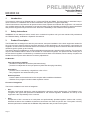
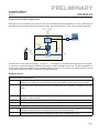
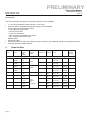
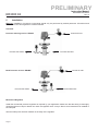
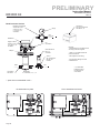
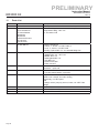
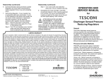
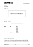
Instruction Manual
dopsmd54161xen2
Rev. A
PRELIMINARY
ER3000 Kit
ER3000 Kits
ER3P-XXXXXXXXXXX
ER3B-XXXXXXXXXXX
Contents
1
Introduction.............................................2
2Safety Instructions..............................2
3
Product Description.............................2
4Technical Data.........................................4
5
Installation..............................................6
6
Wiring ..........................................................8
6.1General Wiring........................................8
6.2 With Junction Box...................................9
7
Maintenance............................................10
8Tuning ER3000.......................................... 11
8.1 PID Control -System Response to a
Step Change in Setpoint.....................16
8.2 PID Control..............................................16
8.3Saving Data..............................................17
8.4Data Aquisition.......................................17
9
ER3000 Troubleshooting....................18
9.1System Troubleshooting..................18
9.2Leak Paths................................................19
9.3 Isolate Mechanical from
electrical................................................22
9.4Debug Window.........................................22
10Drawings..................................................24
11
Parts List..................................................36
12Appendix....................................................37
12.1 Pressure Transducer........................37
12.2 RS232-485 Converter............................41
PRELIMINARY
Instruction Manual
ER3000 Kit
1
dopsmd54161xen2
Rev. A
Introduction
This manual is valid only for ER3000 Kits I & II of the type ER3P and ER3B. The instructions for individual components must also be considered and are either attached in the appendix or supplied separately.
These instructions are important for all personnel who install, operate and maintain this equipment. It is assumed
only qualified personnel with knowledge of the general safety rules and handling procedures of pressurized fluids
and pressure equipment will perform this work. Ensure the availability of this manual to these personnel.
2Safety Instructions
WARNING! Do not attempt to select, install, use or maintain this product until you have read and fully understood
the TESCOM Safety, Installation & Operation Precautions.
3
Product Description
The ER3000 Kits are designed to ease the procurement, setup and installation of the basic equipment needed for
the most common pressure reducing and back pressure control applications. All the necessary components are
supplied in one kit to save the user time and the inconvenience of not having all the accessories and interconnections
needed to get the system up and running.
The heart of the kit is the ER3000, a unique and flexible electropneumatic closed loop PID controller. The pneumatic
output of the ER3000 loads the dome or air-actuator of a mechanical regulator. The pressure at the control port of
the mechanical regulator is measured by a transducer and fed back to the ER3000, which instantly compares the
feedback to the set point and makes the necessary adjustments.
Kit Benefits:
Very high pressure stability
- pressure is independent of the flow (eliminates droop)
- pressure is independent of the input pressure (eliminates decaying inlet effect)
Automation
- pressure can be controlled by a signal from a PC or PLC
- easy integration into automated test cycles
Data Acquisition
-Pressure data can be transferred to the computer without additional hardware
- Windows Tune program includes a data acquisition routine
Kit Level of Integration
The kits are available in two levels of integration:
• Kit I:
Individual components selected to meet the application’s pressure control requirements. The ER3000 is preconfigured with typical PID parameters established for the selected regulator. Installation and set-up of the
equipment is the responsibility of the customer.
• Kit II:
Components of Kit I mounted on a back-plane and professionally plumbed together. Version with a sturdy,
industrial enclosure also available. All electrical connections are made via junction box. The system is factory
leak and performance tested and the ER3000 PID parameters are pre-set for this system.
Page 2
PRELIMINARY
Instruction Manual
dopsmd54161xen2
Rev. A
ER3000 Kit
Typical Pressure Reducing Application
With both kits, the customer has a choice of the most versatile mechanical regulators to cover a wide range of
applications, both pressure reducing and back pressure, with a selection of the most common sealing materials.
Set -point
4-20 mA
230 V AC
or 24 V DC
RS485/USB
Conv erter
Junction
Box
Control Air
Regulator
ER3000
7.5 bar
Feedback
Sensor
Outlet
Process medium
Air Loaded
Regulator
The set point can be either an analog 4 - 20 mA or 1 ‑ 5 volt signal or an RS485 serial signal from a computer.
A converter to change the signal to RS485 from RS232 or USB is available with the kit. The PID parameters can
be fine tuned using the supplied Tescom software loaded on the PC. In the case of an analog set point, the PC
connection is needed only once for optimizing the PID parameters.
Regulator families
Pressure Reducing Regulators
26-2000
High pressure regulator to control various output ranges up to 10,000 psig/690 bar, segregated
captured vent. Available in SST and brass with a wide selection of seat and O-Ring materials
DK
Highly accurate and sensitive regulator with captured vent for low pressure (90 psig/6 bar) or mid
range applications (600 psig/40 bar) requiring significant flow capabilities. Available in SST and
brass.
44-5200
Piston sensed, venting regulator for mid-pressure range, low flow applications (600 psig/40 bar).
Available in SST and brass.
Flow booster Low pressure (90 psig/6 bar), high flow diaphragm regulator for air or nitrogen service. Zinc body.
Back Pressure Regulators
26-1700
High pressure regulator to control various back-pressure ranges up to 10,000 psig/690 bar.
Available in SST only with a wide selection of seat and O-Ring materials
54-2100
High pressure regulator to control various back-pressure ranges up to 10,000 psig/690 bar.
Specially designed for hydraulic applications (metal seat), available in SST only.
Page 3
PRELIMINARY
Instruction Manual
dopsmd54161xen2
Rev. A
ER3000 Kit
Accessories:
The Kits are shipped with all the accessories needed for easy installation:
• 4 – 20 mAmp Feedback Transducer with 1/4" NPT port
•Pressure reducing regulator with gage to supply air to the ER3000.
•Set of commonly used assembly items:
• 8/32 UNC Mounting screws
•ER vent port muffler
• T-piece for transducer
•NPT connector for ER3000 to air loader
•NPT plug and cable strain relief
•ER3000 cable
• Transducer cable
•Optional junction box with power supply for easy connection of the ER3000, transducer and setpoint source
• Converter options of USB or RS232.
4Technical Data
Dash
Code
Regulator
Series
Transducer
pressure
range
psig/bar
Max. Input
Pressure
psi/bar
Flow
Coefficients
Body
Material
Temperature
°F (°C)
Venting
Weight
approx.
lbs. (kg)
Cv: 1.5
Zinc
39 to 118
(+4 to +48)
yes
1.6 (0.75)
Cv: 2.5
Zinc
39 to 118
(+4 to +48)
yes
1.6 (0.75)
Cv: 0.35
Brass
-4 to 163
(-20 to +73)
yes
captured
3.9 (1.8)
Cv: 0.35
Brass
-4 to 163
(-20 to +73)
yes
captured
6.2 (2.8)
Cv: 0.15
Brass
SST
-13 to 199
(-25 to +93)
yes
4.4 (2.0)
Cv: 0.06
Brass
SST
-13 to 199
(-25 to +93)
yes
captured
7.7 (3.5)
Cv: 0.06
Brass
SST
-13 to 199
(-25 to +93)
yes
captured
7.7 (3.5)
Cv: 0.06
Brass
SST
-13 to 199
(-25 to +93)
yes
captured
7.7 (3.5)
Cv: 0.06
Brass
SST
-13 to 199
(-25 to +93)
yes
captured
7.7 (3.5)
ER3P-X Pressure Reducing Regulators
A
Flow
Booster
0 - 100/
0-6
B
Flow
Booster
0 - 100/
0-6
C
DK, dome
loaded
0 - 100/
0-6
D
DK, air
loaded
0 - 100/
0-6
E
44-5200
0 - 500/
0 - 40
F
26-2000
0 - 1000/
0 - 100
G
26-2000
0 - 2000/
0 - 160
H
26-2000
0 - 5000/
0 - 400
J
26-2000
0 - 10,000/
0 - 600
Page 4
300/20
1000/70
3500/240
Brass:
6000/414
SST:
10,000/690
PRELIMINARY
Instruction Manual
dopsmd54161xen2
Rev. A
Dash
Code
Regulator
Series
ER3000 Kit
Transducer
psig/bar
Max. Input
Pressure
psig/bar
Flow
Coefficients
Body
Material
Temperature
°F (°C)
Venting
Weight
approx.
lbs. (kg)
ER3B-X Back Pressure Regulators
A
26-2100
1450/100
Cv: 0.08
SST
-13 to 165
(-25 to +74)
NA
7 (3.2)
B
26-2100
2320/160
Cv: 0.08
SST
-13 to 165
(-25 to +74)
NA
7 (3.2)
C
26-2100
5800/400
Cv: 0.08
SST
-13 to 165
(-25 to +74)
NA
7 (3.2)
D
26-2100
8700/600
Cv: 0.08
SST
-13 to 165
(-25 to +74)
NA
7 (3.2)
F
26-1700
1450/100
Cv: 0.14
SST
-40 to 165
(-40 to +74)
NA
7 (3.2)
G
26-1700
2320/160
Cv: 0.10
SST
-40 to 165
(-40 to +74)
NA
7 (3.2)
H
26-1700
5800/400
Cv: 0.10
SST
-40 to 165
(-40 to +74)
NA
7 (3.2)
J
26-1700
8700/600
Cv: 0.10
SST
-40 to 165
(-40 to +74)
NA
7 (3.2)
10,000/690
Specifications
ER3000
Power supply
24 V DC (22V to 28V) 180 mA Nominal
Supply Media
Clean, dry, inert gases or shop air
Supply Pressure
110 psig/7.5 bar nominal, maximum 120 psig/8.0 bar
Input signals
Set Point: 4-20 mA, 1-5 V or digitally RS485 Feedback: 4-20 mA, 1-5 V
Housing
NEMA 4X / IP64 weight 1 kg
Please see ER3000 User Manual for additional specifications
All Regulators
See Individual Drawings for regulator specifications
Pressure Transducer
Output Signal
4 - 20 mAmp, 1 - 5 V DC
Accuracy
0.25% or 0.1%
Connection
¼" NPT
Power Supply
24 V DC, connector: 175301-803A
Housing
NEMA4X / IP65, weight: 0.3 kg
Page 5
PRELIMINARY
Instruction Manual
ER3000 Kit
5
dopsmd54161xen2
Rev. A
Installation
Warning: Installation of pressure components should only be performed by trained personnel. All national and
international rules and regulations must be followed.
Overview
Pressure reducing version “ER3PP”
Process Gas Outlet
Back Pressure version “ER3BP”
Process Gas Outlet
Control Air Inlet
Process Gas Inlet
Control Air Inlet
Process Gas Inlet
Mechanical Regulator
Install the mechanical pressure regulator as required by your application. Make sure that the tubing is thoroughly
cleaned and that no chips or debris can reach the regulator valve. A 40 µm filter is recommended to be installed in
the inlet path.
Inlet and outlet ports are laser marked on the body of the regulator.
Page 6
Instruction Manual
PRELIMINARY
dopsmd54161xen2
Rev. A
ER3000 Kit
ER3000
ER3000 mounting holesER3000 ports
The ER3000 can be installed either directly on top of the regulator’s air loader using the supplied adapter or using
tubing between ER3000 outlet and regulator dome/air loader.
• Length between the ER and the dome of the regulator should be as short as possible – as the length increases,
so does the response time.
• Tubing between the ER and regulator must be able to handle up to 120 psig/8.5 bar.
• The ER can be oriented in any position.
• Connect ER3000 inlet port (NPT 1/8") to the air supply (direct shop air or control air regulator). Tubing must be
able to handle up to 120 psig/8.5 bar.
• Installation of a 40 µm filter is recommended on the inlet of the ER3000.
• The supplied muffler may be installed in the ER exhaust port (NPT 1/8") if desired.
Transducer
Connect transducer on the control port of the regulator using the supplied T-piece
The position of the transducer should be close to the regulator for a fast regulator response (no delay time). If the
response time is not critical to the application, the transducer can be mounted close to the point of use.
Wiring
Wiring is simplified using the Junction Box, minimizing noise problems caused by long, messy cable lengths. For
details see chapter on “Wiring”. When installing, consider the following:
•Mount Junction Box close to the ER3000.
• Run the ER cable to the junction box, feeding it through the strain relief marked ER. Shorten cable as needed
and connect to terminal strip.
• Run the transducer cable to the junction box,feeding it through the strain relief marked Transducer. Shorten
cable as needed and connect to terminal strip.
• Connect power supply to the appropriate source.
• Analog control: Connect set point signal to the junction box.
Serial control: Connect RS485 cable to the junction box and the appropriate computer port.
See Section 6 for wiring details.
Page 7
PRELIMINARY
Instruction Manual
ER3000 Kit
dopsmd54161xen2
Rev. A
System Leak Check
•Switch on the ER3000’s power supply.
•Slowly apply ER supply pressure and then process pressure. Set the output pressure to a safe value.
• Check all fittings for tightness using leak test fluid. No bubbles should be seen.
ER3000 Tuning
• In many applications, the standard factory settings will work satisfactorily, but to get the best performance,
“tuning” of the control loop parameters may be required (see chapter 8 and ER3000 user manual for detailed
information). When tuning, use conditions similar to the final application (i.e. similar pressures, flow, and
medium). A tuning procedure is provided in the ER3000 User Manual. There is also “Help” available in the Tune
program itself, accessed by going to the Help menu or by pressing ‘F1’. See Section 8 for further tuning tips.
6
Wiring
6.1General Wiring
The following diagram shows the typical electrical connection of the ER3000. You will find additional information in
the ER3000 User Manual.
Page 8
PRELIMINARY
Instruction Manual
dopsmd54161xen2
Rev. A
6.2
ER3000 Kit
With Junction Box
Customer supplied cables
1.5 m Cables supplied
connector - open end
Supply (230/120 V AC or 24 V DC)
ER3000
Analog Controls (Set point)
Junction Box
approx. 200 x 200 x 120 mm
IP65
Transducer
Digital Communication (RS485)
Junction Box Schematic
Junction Box AC
+24V DC
0V DC
PE
+24V DC
0V DC
PE
-1ER5
-X1
4
-X1
4
5
brown
violett
3
orange
white
green
pink
2
5
4
5
6
L1
N
+
-
ER 3000
1
red
yellow
blue
grey
7
8
9
black
10
tan
12
11
-1T3
-X1
8
9
10 11
-X1
12 13 14 15 16 17 18 19 20 21 22 23 24 25 26
3
230 V AC
PE
+24V DC
0V DC
Data +
Data Setpoint Setpoint +
2
7
+24V DC
1
PE
-X1
6
Sensor RS485
Setpoint
Page 9
PRELIMINARY
Instruction Manual
dopsmd54161xen2
Rev. A
ER3000 Kit
Junction Box DC
+24V DC
0V DC
PE
+24V DC
0V DC
PE
-1ER5
brown
violett
3
orange
white
4
yellow
black
10
6
blue
tan
12
2
4
5
-X1
-X1
2
3
PE
0V DC
+24V DC
1
24 V
7
-X1
5
ER 3000
1
red
green
grey
pink
7
8
9
11
-X1
6
7
8
9
10 11
12 13 14 15 16 17 18 19 20 21 22 23 24 25 26
+24V DC
Signal
PE
+24V DC
0V DC
Data +
Data Setpoint Setpoint +
-X1
1A/250V
4
Sensor RS485 Setpoint
Maintenance
The maintenance and repair of pressure equipment must only be performed by trained experts!
Since every application exists under different conditions, the user is responsible for establishing a maintenance
program based on their unique situation. Until enough data is collected to set up a schedule, we recommend a
6 - 12 month check of the following:
1.Visual check for damages, especial of the tubing, electrical components and cables
2.Functional check
3.Check for leaks
A periodic calibration of the feedback pressure transducer depends on the user’s requirements. Tescom recommends
a yearly calibration.
Page 10
PRELIMINARY
Instruction Manual
dopsmd54161xen2
Rev. A
ER3000 Kit
8Tuning ER3000
If additional tuning is desired, the ER3000 Windows Tune program is provided on the CD included in the ER kit package.
See Sections 8.1 and 8.2 for general PID control information
Change for desired mode of operation.
“Internal or External”
Typically External mode is used.
For display only, should match the
Feedback source.
Change for optimum performance.
Only used with “F” model ERs
Factory set: Do not change
See variable #26 and #27 for factory setting
Proportional (P): Right foot on gas pedal, the harder you press the faster you go.
Derivative (D):
Left foot on the brake pedal, the harder you press the faster you stop.
Integral (I):
Back seat driver, the bigger the number the louder they are shouting for you to correct your driving.
Integral Min:
Back seat driver, the more negative the number the longer they are shouting that you are beyond
your setpoint. Correction will be down to the target.
Integral Max:
Back seat driver, the bigger the number the longer they are shouting that you are not at your
setpoint. Correction will be up to the target.
30
D – Increasing derivative reduces the amount of initial overshoot
I & Imin – Increasing the integral min can help bring the feedback down to the setpoint
I & Imax
– Increasing the integral max
can help bring the feedback
up to the setpoint
20
P
Setpoint
Feedback
10
P
I & Imin
0
0
Page 11
50
100
150
200
250
300
350
400
PRELIMINARY
Instruction Manual
ER3000 Kit
Typical tuning sequence: increase Proportional for faster response.
Typical Range: 500 to 3000
Too much Proportional will make unstable.
Optimal Proportional with little ringing.
Page 12
dopsmd54161xen2
Rev. A
PRELIMINARY
Instruction Manual
ER3000 Kit
Increase Derivative to eliminate over-shoot.
Typical Range: 20 to 200
Zoom in to see accuracy.
Make Integral approximately 50% of proportional term.
Typical Range: 50% of P term down to zero
Increase Integral maximum to bring the feedback up.
Typical Range: 5 to 300
Has no effect if Integral term = 0
Page 13
dopsmd54161xen2
Rev. A
PRELIMINARY
Instruction Manual
ER3000 Kit
Zoom in on decreasing setpoint.
Make Integral Minimum more negative to bring the feedback down to setpoint.
Typical Range: -5 to –300
Has no effect if Integral term = 0
Too much integral may cause oscillations.
Page 14
dopsmd54161xen2
Rev. A
PRELIMINARY
Instruction Manual
ER3000 Kit
dopsmd54161xen2
Rev. A
Adding Integral Dead band may remove oscillation.
Typical Range: 0.03 to 0.5
Another way to remove oscillations:
• Change Frequency Response of ER3000
• Change variable 12 to a “0”.
• Increase variable 13 to delay in increments of 25 milliseconds. (“0”=25 ms, 1=25 ms, 2=50 ms….)
Firmware Version 716
Limit Internal Sensor:
• Variable 20 limits maximum
• Variable 19 limits minimum
Page 15
PRELIMINARY
Instruction Manual
dopsmd54161xen2
Rev. A
ER3000 Kit
8.1
PID Control -System Response to a Step Change in Setpoint
• Optimal PID parameters result in a “Critically-Damped” response
• Not enough “gain” results in an “Over-Damped” response
• Too much “gain” results in an “Under-Damped” response
Ov er-D am ped
Step Change in Setpoint
Feedback Response
Under- Da mp ed
Cr itically-D am ped
Ti me
8.2
PID Control
Math Model
Page 16
PRELIMINARY
Instruction Manual
ER3000 Kit
dopsmd54161xen2
Rev. A
8.3Saving Data - PID Configuration
8.4Data Acquisition
•Press Start when ready to collect data,
may press again to stop or you can let
collect total “Number of Samples”
•Choose file name and location to store
on hard drive
•This is as fast as Windows will allow
•Can be any size needed
•Used for easy import to excel
•Stores Header Comments in file
Page 17
PRELIMINARY
Instruction Manual
ER3000 Kit
9
ER 3000 Troubleshooting
9.1System Troubleshooting
Communications
Check LED’s on RS485 converter and ER3000 circuit boards.
DLL in use error is related to com port access.
Try another Com port.
Page 18
dopsmd54161xen2
Rev. A
PRELIMINARY
Instruction Manual
dopsmd54161xen2
Rev. A
ER3000 Kit
Pressure
Read/write windows can be used to monitor a digital display of the system pressures.
Variable #1 is the analog setpoint.
1 Vdc or 4 mA is equal to 400 counts. 5 Vdc or 20 mA is equal to 3700 counts.
Variable #5 is the external feedback.
1 Vdc or 4 mA is equal to 400 counts. 5 Vdc or 20 mA is equal to 3700 counts.
Variable #6 is the internal feedback.
400 counts is equal to 0 psi. 3700 counts is equal to 100 psi.
9.2Leak Paths
Pressure oscillations are often caused by leaks in the system. Common leak paths are shown below. Use the
following leak check procedure to find and eliminate all leaks.
Common Leak
Paths
Pilot gas
Inlet Process
Page 19
Outlet Process
PRELIMINARY
Instruction Manual
ER3000 Kit
Leak Check
Save current parameters
Change PID values to “0”
Page 20
dopsmd54161xen2
Rev. A
PRELIMINARY
Instruction Manual
ER3000 Kit
Internal pressure should not decay more then 0.1 psig in 20 seconds.
Restore PID parameters
Page 21
dopsmd54161xen2
Rev. A
PRELIMINARY
Instruction Manual
dopsmd54161xen2
Rev. A
9.3
ER3000 Kit
Isolate Mechanical from electrical
To ensure that the regulator is working properly, test if using one of the methods shown below.
With the ER3000 in internal feedback mode, both systems will perform the same.
Hand loaded self
venting regulator
Pilot gas
Pilot gas
Inlet Process
Outlet Process
Inlet Process
Outlet Process
9.4Debug Window
By enabling the debug variable, 2 extra parameters can be monitored on the plot screen. In addition, data on these
2 parameters will be collected when running the Windows Tune data acquisition routine.
With main menu active Press “F10”
Page 22
PRELIMINARY
Instruction Manual
dopsmd54161xen2
Rev. A
ER3000 Kit
Click to Enable
Adds internal pressure
To Plot window
Change to variable “6”
Scale is always
0 psig to 100 psig
for internal pressure
Page 23
PRELIMINARY
Instruction Manual
dopsmd54161xen2
Rev. A
ER3000 Kit
10Drawings
The drawings in this manual are for reference only. For most up to date drawings please contact your
local TESCOM representative.
Pressure Reducing Version
ER3000SI-1
Regulator for ER supply
44-5212-241V-003
ø 6mm for A, B, C, D
ø 1/4” for E, F, G
see table 6
Gauge
Junction box
to be connected to ER
see tables 9, 10
Inlet
supply air
Supply air elbow
ø 6mm for A, B, C, D
ø 1/4” for E, F, G
see table 6
Adapter *
PG
connections
Remarks:
- PID-Parameters to be loaded into ER
according to selected regulator
- Cables 1.5 m included for ER and
pressure transducer
Outlet transducer
NPT 1/4”
see table 7
- Pilot regulator is self venting
- All compression fittings are made
of stainless steel
Outlet
T-Piece
ass. to transducer
tube dia. acc
to table 6
Inlet
Connections
see table 6
*= not assembled
Dotted lines stand
for tubes that are
not included
Regulator
see tables 1, 2, 3, 4, 5
*: parts are not assembled in Kit 1
Kit assembled on plate
Kit in assembled enclosure
Page 24
PRELIMINARY
Instruction Manual
dopsmd54161xen2
Rev. A
ER3000 Kit
Available Combinations (SELECTION CHART)
Inlet & outlet
compression fittings
max. inlet
pressure
psig / bar
7 – Vespel®
8 – PEEK
B – Buna-N®
D – Buna-N®
T – Viton®
U – Urethane
V – Kalrez®
Z – EP
A – ø6 mm
B – ø8 mm
C – ø10 mm
D – ø12 mm
E – 1/4"
F – 3/8"
G – 1/2"
A: Flow Booster
87 / 6
300 / 20
1.5
n
n
+
n
n
n
+
+
n
n
n
n
+
+
+
+
+
+
+
B: Flow Booster
87 / 6
300 / 20
2.5
n
n
+
n
n
n
+
+
n
n
n
n
n
n
+
+
n
+
+
C: DK Dome Loaded
87 / 6
1000 / 7
0.35
+
+
n
+
n
+
n
+
+
n
n
+
+
+
+
+
+
+
+
D: DK Air Loaded
580 / 40
1000 / 7
0.35
+
+
n
+
n
+
n
+
+
n
n
+
+
+
+
+
+
+
+
E: 44-52V Air Loaded
580 / 40
3500 / 240
0.15
+
+
n
n
+
n
n
n
+
n
n
n
+
+
n
n
+
n
n
F: 26-20 Air Loaded
1450 / 100
15000 / 1035
0.06
+
+
n
n
+
+
n
+
+
+
+
+
+
+
+
+
+
+
+
G: 26-20 Air Loaded
2320 / 160
15000 / 1035
0.06
+
+
n
n
+
+
n
+
+
+
+
+
+
+
+
+
+
+
+
H: 26-20 Air Loaded
5800 / 400
15000 / 1035
0.06
+
+
n
n
+
+
n
+
+
+
+
+
+
+
+
+
+
+
+
J: 26-20 Air Loaded
8700 / 600
15000 /1035
0.06
+
+
n
n
+
+
n
+
+
+
+
+
+
+
+
+
+
+
+
regulator
Series
+ available
n
not available
Page 25
Cv
Pressure
Range
psig / bar
0 –CTFE
O-Ring
Z – Zinc
Seat
6 – SST
body
1 – Brass
regulator
PRELIMINARY
Instruction Manual
dopsmd54161xen2
Rev. A
ER3000 Kit
Back Pressure Version
Regulator for ER supply
44-5212-241V-003
ø 6mm for A, B, C
ø 1/4“ for E, F, G
see table 6
Gauge
Junction box
to be connected to ER
see tables 9, 10
Inlet
supply air
ER3000SI-1
Supply air elbow
ø 6mm for A, B, C, D
ø 1/4“ for E, F, G
see table 6
PG
connections
Outlet transducer
NPT 1/4“
see table 7
Adapter *
T-Piece
ass. to transducer
tube dia. acc
to table 6
Outlet
Remarks:
- PID-Parameters to be loaded into ER
according to selected regulator
- Cables 1.5 m included for ER and
pressure transducer
- Pilot regulator is self venting
- All compression fittings are made
of stainless steel
Inlet
*= not assembled
Connections
see table 6
Regulator
see tables 1, 2, 3, 4, 5
Dotted lines stand
for tubes that are
not included
*: parts are not assembled in Kit 1
Kit assembled on plate
Page 26
Kit in assembled enclosure
PRELIMINARY
Instruction Manual
dopsmd54161xen2
Rev. A
ER3000 Kit
Available Combinations (SELECTION CHART)
Inlet & outlet
compression fittings
regulator
Series
Pressure
Range
psig / bar
max. inlet
pressure
psig / bar
3 – Teflon®
7 – Vespel®
D – Buna-N®
T – Viton®
U – Urethane
V – Kalrez®
Z – EP
A – ø6 mm
B – ø8 mm
C – ø10 mm
D – ø12 mm
E – 1/4"
F – 3/8"
G – 1/2"
O-Ring
0 – CTFE
Seat
6 – SST
body
Cv
regulator
A: 54-2100 Air Loaded
1450 / 100
1000 / 690
0.08
+
n
n
+
+
+
+
+
+
+
+
+
+
+
+
+
B: 54-2100 Air Loaded
2320 / 160
1000 / 690
0.08
+
n
n
+
+
+
+
+
+
+
+
+
+
+
+
+
C: 54-2100 Air Loaded
5800 / 400
1000 / 690
0.08
+
n
n
+
+
+
+
+
+
+
+
+
+
+
+
+
D: 54-2100 Air Loaded
8700 / 600
1000 / 690
0.08
+
n
n
+
+
+
+
+
+
+
+
+
+
+
+
+
F: 26-1700 Air Loaded
1450 / 100
1000 / 690
0.14
+
n
+
+
+
+
n
n
n
+
+
+
+
+
+
+
G: 26-1700 Air Loaded
2320 / 160
1000 / 690
0.1
+
+
n
+
+
+
n
n
n
+
+
+
+
+
+
+
H: 26-1700 Air Loaded
5800 / 400
1000 / 690
0.1
+
+
n
+
+
+
n
n
n
+
+
+
+
+
+
+
J: 26-1700 Air Loaded
8700 / 600
1000 / 690
0.1
+
+
n
+
+
+
n
n
n
+
+
+
+
+
+
+
+ available
n
not available
Page 27
PRELIMINARY
Instruction Manual
ER3000 Kit
Junction Box
Page 28
dopsmd54161xen2
Rev. A
Instruction Manual
dopsmd54161xen2
Rev. A
PRELIMINARY
ER3000 Kit
Regulator 26-2000 Series
Page 29
PRELIMINARY
Instruction Manual
ER3000 Kit
Regulator DK Series
Page 30
dopsmd54161xen2
Rev. A
Instruction Manual
dopsmd54161xen2
Rev. A
PRELIMINARY
ER3000 Kit
Regulator Flow Booster
Page 31
PRELIMINARY
Instruction Manual
ER3000 Kit
Regulator 44-5200 Series
Page 32
dopsmd54161xen2
Rev. A
Instruction Manual
dopsmd54161xen2
Rev. A
PRELIMINARY
ER3000 Kit
Back Pressure Regulator 26-1700 Series
Page 33
PRELIMINARY
Instruction Manual
ER3000 Kit
Hydraulic Back Pressure Regulator 54-2100 Series
Page 34
dopsmd54161xen2
Rev. A
Instruction Manual
dopsmd54161xen2
Rev. A
PRELIMINARY
ER3000 Kit
Control Air Regulator 44-5200 Series
Page 35
PRELIMINARY
Instruction Manual
dopsmd54161xen2
Rev. A
ER3000 Kit
11
Parts List
#
Part No.
Description
1
ER3000SI-1
Electro pneumatic Controller
1
26-20xx x2x A2x0
DK-D17xxV9Axx9
DK-A16xxV9Axx9
269-529-04
269-529-06
44-52x6-241VA-027
26-176x-2xA
54-216x-x2xA
Mechanical Regulator, air loaded including Elbow
compression fitting - NPT 1/4"
“x”: see order code
1
D51656-NB-xxx
Pressure transducer
± 0.25%, 4 - 20 mA, 1/4" NPT male or
± 0.1%, 4 - 20 mA, 1/4" NPT male
including T-piece NPT 1/4", 2 x selected fitting size
1
D54102
Assembly material:
1 Adapter NPT 1/4" - NPT 1/8"
1 Muffler, NPT 1/4"
1 Cable gland NPT 1/2"
1 Cap NPT 1/2"
4 screws 8-32 UNC
1 Filter 1/8" NPT
1
85138-01
ER3000 Cable, 12 wire, shielded, 1.5 m circuit board
connector – open end
1
D54115
Transducer Cable, 2 wire, shielded,
1.5 m DIN 175301-803A – open end
(1)
44-5212-241V-002
Regulator inlet max. 240 bar / 3000 psi,
outlet 7 bar / 100 psi, Cv=0.06, venting,
brass body, 1/4" NPT ports
with
1 Gauge 10 bar (150 psi), 63 mm, brass, 1/4" NPT Tube
fittings
(1)
ER3JB-xx
Junction Box
(1)
85061
Converter RS485 – RS232
(1)
82948
Converter RS485 - USB
Page 36
Instruction Manual
PRELIMINARY
dopsmd54161xen2
Rev. A
ER3000 Kit
12Appendix
•Pressure Transducer
• RS485 Converter
• Instructions for Use of Regulator
see attached pdf files
26-20, 54-20
dopsmD44307xde2.pdf
26-17, 54-21
dopsmD43746xde2.pdf
44-52
dopsmD43747xde2.pdf
DK
flow booster
269529 flow booster.pdf
•ER3000 Catalog pages
ER3000 User’s Manual
see pdf file, or download from the Tescom Internet page:
www.Tescom.com
for the English version
www.Tescom-Europe.com for the German version
•ER3000 Software
please download latest version from the Tescom Internet page:
www.Tescom.com
12.1 Pressure Transducer
Order Code - Bestellcode:
D51656 - NB - xxx
NB:
NPT1/4"
xxx:
1
1 bar
2,5
2,5 bar
4
4 bar
6
6 bar
10
10 bar
25
25 bar
40
40 bar
60
60 bar
100
100 bar
250
250 bar
400
400 bar
600
600 bar
Page 37
PRELIMINARY
Instruction Manual
ER3000 Kit
dopsmd54161xen2
Rev. A
Description
This series of pressure transmitters has been carefully designed to cover the majority of industrial applications with
instruments readily available from stock.
Compact design and robust construction make these instruments suitable for all applications in machine construction,
process control, laboratory or quality and materials testing equipment.
There is an extraordinary range of instrument variants resulting from the fact that various mechanical and electrical
connections can be combined with each other to almost any extent.
Structure
All wetted parts are made of stainless steel and are hermetically welded. Therefore there is no need for additional
sealing material, which could possibly react with the pressure medium. The compact case is also made of stainless
steel and provides IP 65 ingress protection (special versions up to IP 68).
The transmitters can be supplied with a non-stabilized direct voltage of 10 (14) … 30 V and provide standard
industrial output signals.
The model S-11 with flush diaphragm is particularly suitable for the measurement of viscous fluids or media containing
particulates that may clog the pressure connection of standard industrial transmitters. Thus, a trouble-free pressure
measurement is ensured. Pressure transmitters with flush diaphragm are available in pressure ranges from 0 ... 0.1
bar to 0 ... 600 bar. For applications with higher temperature requirements an integrated cooling element enables
medium temperatures of up to 150 °C (302 °F).
For the pressure ranges from 0 … 0.25 bar up to 0 ... 1000 bar the pressure transmitters can be delivered for oxygen
applications (technical safety check of the BAM, Bundesanstalt für Materialforschung und -prüfung available).
Page 38
Instruction Manual
dopsmd54161xen2
Rev. A
PRELIMINARY
ER3000 Kit
Page 39
PRELIMINARY
Instruction Manual
dopsmd54161xen2
Rev. A
ER3000 Kit
Dimensions
Connection NB
DIN 175301-803 A
L-connector
1/4 NPT
per “Nominal size for US standard tapered pipe
thread NPT”
Electrical Connection
Page 40
Instruction Manual
dopsmd54161xen2
Rev. A
PRELIMINARY
ER3000 Kit
12.2 RS232-485 Converter
RS2485 to RS232 Converter including 9 to 25 pin cable
Part number: 85061
USB to RS485 Converter
Part number: 82948
Instruction for using the datalink communications
USB to RS485 converter with the ER3000
Dip Switch Setup:
Set the 4 Dip Switches located on the back of converter to RS485, ECHO OFF, 2 WIRE,
2 WIRE
Wiring:
Attach the green wire from the ER3000 to the Converter´s TDA(-) PIN and the blue wire to the TDB(+) Pin
Driver Installation:
Follow directions provided by Datalink
Communications
Page 41
PRELIMINARY
Instruction Manual
ER3000 Kit
For your own notes
Page 42
dopsmd54161xen2
Rev. A
Instruction Manual
dopsmd54161xen2
Rev. A
PRELIMINARY
ER3000 Kit
For your own notes
Page 43
PRELIMINARY
Instruction Manual
dopsmd54161xen2
Rev. A
ER3000 Kit
WARNING! Do not attempt to select, install, use or maintain this product until you have read and fully understood the TESCOM Safety,
Installation & Operation Precautions.
The contents of this publication are presented for informational purposes only, and while every effort has been made to ensure their accuracy, they are not to be construed as
warranties or guarantees, expressed or implied, regarding the products or services described herein or their use or applicability. We reserve the right to modify or improve the
designs or specifications of such product at any time without notice.
USA
T +1 800 447 1250
+1 763 241 3238
[email protected]
www.tescom.com
Germany
T +49 38823 31-287
[email protected]
www.tescom-europe.com
United Kingdom
T +44 1698 424 254
[email protected]
www.tescom.com
DOPSMD54161XEN2 ©Tescom Corporation, 2011; All Rights Reserved.
1/11
Tescom is a business unit of Emerson Process Management Regulator Technologies, Inc.
Trademarks are property of divisions of Emerson Process Management.
China
T +86 21 2892 9499
[email protected]
www.tescom.com
United Arab Emirates
T +971 4 811 8443
[email protected]
www.tescom.com