1
Phoenix Technologies Ltd.
PhoenixBIOS 4.0
Revision 6
User's Manual
Phoenix Technologies Ltd., 411 E. Plumeria, San Jose, CA 95134
Copyright
PhoenixBIOS 4.0 User's Manual
22 June 2000
2000 Phoenix Technologies Ltd.
All Rights Reserved.
Disclaimer
The programs are provided "as is" without warranty of any kind either expressed
or implied, including but not limited to the implied warranties of merchantability
and fitness for a particular purpose. This publication could contain technical
inaccuracies or typographical errors. Changes are periodically made to the
information herein; these changes will be incorporated in new editions of this
publication. Phoenix Technologies Ltd. is without obligation to notify any
person of such revisions or changes.
Purpose of Document
This guide explains how to configure your PC and optimize its performance
using the Setup program. It also explains how to use the BIOS function calls in
writing computer programs.
PB4.0 UM 06.22.00
Page ii
Phoenix Technologies Ltd.
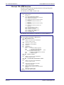
Contents
About This Manual ...................................................................................... 1
Chapter 1The Setup Guide ......................................................................... 2
The Main Menu ................................................................................... 2
The Menu Bar ............................................................................. 3
The Legend Bar .......................................................................... 3
The Field Help Window .............................................................. 4
The General Help Window ......................................................... 4
Main Menu Selections ................................................................ 4
Master and Slave Sub-Menus .................................................... 5
Memory Cache ........................................................................... 7
Memory Shadow......................................................................... 8
Boot Sequence ........................................................................... 9
Keyboard Features ................................................................... 10
Boot Menu......................................................................................... 11
The Advanced Menu......................................................................... 12
Advanced Chipset Control (No PCI)......................................... 13
Advanced Chipset Control Menu (PCI BIOS) ........................... 14
PCI Devices Menu .................................................................... 15
I/O Device Configuration Menu................................................. 16
The Security Menu............................................................................ 18
The Power Menu............................................................................... 19
The Exit Menu................................................................................... 21
Saving Values........................................................................... 21
Exit Discarding Changes .......................................................... 21
Load Setup Defaults ................................................................. 21
Discard Changes ...................................................................... 22
Save Changes .......................................................................... 22
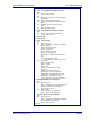
PhoenixBIOS Messages ................................................................... 23
Chapter 2 Boot Utilities ............................................................................. 26
Phoenix QuietBoot ............................................................................ 26
Press <ESC> ............................................................................ 26
Press <F2> ............................................................................... 26
POST Error............................................................................... 26
Keyboard Input Request........................................................... 27
Phoenix MultiBoot ............................................................................. 27
The Boot First Menu ................................................................. 27
Chapter 3 Phoenix Phlash ........................................................................ 28
Installation......................................................................................... 28
Create the Crisis Recovery Diskette................................................. 28
Updating the Crisis Recovery Diskette ............................................. 29
Executing Phoenix Phlash ................................................................ 29
Crisis Recovery Mode....................................................................... 30
Chapter 4 Programmer's Guide ................................................................ 31
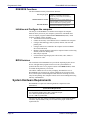
What is a ROM BIOS?...................................................................... 31
ROM BIOS Functions ............................................................... 32
Initialize and Configure the computer ....................................... 32
BIOS Services .......................................................................... 32
System Hardware Requirements...................................................... 32
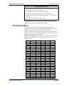
Fixed Disk Tables ............................................................................. 33
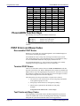
PhoenixBIOS Function Keys ............................................................ 34
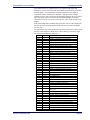
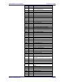
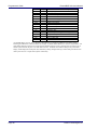
POST Errors and Beep Codes ......................................................... 34
Recoverable POST Errors........................................................ 34
Terminal POST Errors .............................................................. 34
Test Points and Beep Codes .................................................... 34
PhoenixBIOS 4.0 Services ............................................................... 39
Phoenix Technologies, Ltd.
Page iii
Contents
PhoenixBIOS 4.0 User's Manual
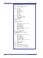
BIOS32 Service Directory......................................................... 39
Interrupt 10h–Video Services ................................................... 41
Interrupt 11h–Return System Information ................................ 43
Interrupt 12h–Return Memory Size........................................... 43
Interrupt 13h–Diskette Services ............................................... 43
Interrupt 13h–Fixed Disk Services............................................ 46
Interrupt 13h–Extended Fixed Disk Services ........................... 49
Interrupt 13h–Bootable CD-ROM Services .............................. 50
Interrupt 14h–Serial Services ................................................... 51
Interrupt 15h–System Services ................................................ 53
Interrupt 15h–APM Services..................................................... 56
Interrupt 15h–Big Memory Services ......................................... 59
Interrupt 15h–PS/2 Mouse Services ......................................... 60
Interrupt 15h–EISA Services .................................................... 61
Interrupt 16h–Keyboard Services ............................................. 63
Interrupt 17h–Parallel Printer Services ..................................... 64
Interrupt 17h–EPP Services ..................................................... 64
Interrupt 1Ah–Time of Day Services......................................... 68
Interrupt 1Ah–General PCI Services ........................................ 68
PnP Run-Time Services ........................................................... 70
SMBIOS Services ..................................................................... 74
MultiBoot III Run-Time Services ............................................... 76
BIOS Data Area ................................................................................ 77
Extended BIOS Data Area........................................................ 79
Interrupt Vectors ............................................................................... 80
Index ......................................................................................................... 81
Page iv
Phoenix Technologies Ltd.
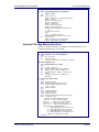
About This Manual
This manual is divided into the following chapters:
Chapter 1 - The Setup Guide
This chapter describes a typical menu-driven Phoenix Setup program, which
allows you to specify changes in the computer hardware (e.g. add a new diskette
drive) and optimize system performance. Setup maximizes your control over
your system's features and performance.
This Setup Guide is only an example. The Setup menus on your computer may
be quite different. Consult the Setup manual supplied with your computer.
Chapter 2 - PhoenixBIOS Utilities
This chapter describes two new programs that give you more control over the
boot process:
• Phoenix QuietBoot
• Phoenix MultiBoot
Chapter 3 - Phoenix Phlash
This chapter describes how to use the Phoenix Phlash utility for upgrading your
BIOS without having to replace the BIOS ROM chip.
Chapter 4 - Programmer's Guide
This chapter gives programmers and expert PC users a detailed description of
PhoenixBIOS. It contains the following sections:
• Overview
• Hardware Requirements
• Fixed Disk Tables
• Function Keys
• POST Errors and Beep Codes
• BIOS Services
• BIOS Data Area
• Interrupt Vector Table
Phoenix Technologies, Ltd.
Page 1
1
The Setup Guide
With the PhoenixBIOS Setup program, you can modify BIOS settings and
control the special features of your computer. The Setup program uses a number
of menus for making changes and turning the special features on or off.
Note: The menus shown here are from a typical system. The actual menus
displayed on your screen may be quite different and depend on the hardware and
features installed in your computer. For more accurate information about your
BIOS Setup program, consult your system manual or contact the manufacturer.
The Main Menu
To start the PhoenixBIOS Setup utility:
Turn on or reboot your system. PhoenixBIOS displays this message:
Press <F2> to enter SETUP
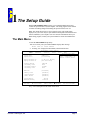
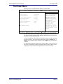
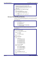
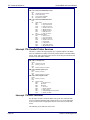
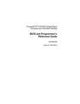
2. Pressing <F2> displays the Main Menu, which looks like this:
Main
PhoenixBIOS Setup Utility
Advanced
Security
Power
Boot
System Time
System Date:
[16:19:20]
[03/02/1994]
Legacy Diskette A:
Legacy Diskette B
[1.44/1.25 MB 3½”]
[Not Installed]
Primary Master
Secondary Slave
Secondary Master
Secondary Slave
Numlock:
<Tab>, <Shift-Tab>, or
<Enter> selects field
6449 MB
None
CD-ROM
None
[Disabled]
Memory Cache
System Shadow
Video Shadow
System Memory
Extended Memory
F1 Help
ESC Exit
Exit
Item Specific Help
¦ Select Item
¥Select Menu
[Enabled]
[Enabled]
[Enabled]
640 kB
31744 kB
-/+ Change Values
Enter Select
Sub-Menu
F9 Setup Defaults
F10 Save and Exit
See p. 4 for a description of the fields on this menu.
Phoenix Technologies, Ltd.
Page 2
PhoenixBIOS 4.0 User's Manual
The Setup Guide
The Menu Bar
The Menu Bar at the top of the window lists these selections:
Main
Advanced
Security
Power
Exit
Use the left and right
Use this menu for basic system
configuration.
Use this menu to set the Advanced
Features available on your system's
chipset.
Use this menu to set User and Supervisor
Passwords and the Backup and VirusCheck reminders.
Use this menu to configure PowerManagement features.
Exits the current menu.
¥ arrow keys to make a selection.
See the section below, "Exiting Setup," for a description on exiting the Main
Menu.
The Legend Bar
Use the keys listed in the legend bar on the bottom to make your selections or
exit the current menu. The chart on the following page describes the legend keys
and their alternates:
Key
<F1> or <Alt-H>
<Esc>
arrow keys
↑ or ↓ arrow keys
<Tab> or <Shift-Tab>
<Home> or <End>
<PgUp> or <PgDn>
<F5> or <->
<F6> or <+> or <Space>
<F9>
¥
<F10>
<Enter>
<Alt-R>
Function
General Help window (See below).
Exit this menu.
Select a different menu.
Move cursor up and down.
Cycle cursor up and down.
Move cursor to top or bottom of window.
Move cursor to next or previous page.
Select the Previous Value for the field.
Select the Next Value for the field.
Load the Default Configuration values for
this menu.
Save and exit.
Execute Command or Select P Submenu.
Refresh screen.
To select an item, use the arrow keys to move the cursor to the field you want.
Then use the plus-and-minus value keys to select a value for that field. The Save
Values commands in the Exit Menu save the values currently displayed in all the
menus.
To display a sub menu, use the arrow keys to move the cursor to the sub menu
you want. Then press <Enter>.
A pointer ( ) marks all sub menus.
Phoenix Technologies Ltd.
Page 3
The Setup Guide
PhoenixBIOS 4.0 User's Manual
The Field Help Window
The help window on the right side of each menu displays the help text for the
currently selected field. It updates as you move the cursor to each field.
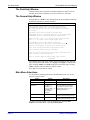
The General Help Window
Pressing <F1> or <Alt-H> on any menu brings up the General Help window that
describes the legend keys and their alternates:
General Help
Setup changes system behavior by modifying the BIOS
Configuration parameters. Selecting incorrect values
may cause system boot failure; load Setup Default values
to recover.
<Up/Down> arrows select fields in current menu.
<PgUp/PgDn> moves to previous/next page on scrollable menus.
<Home/End> moves to top/bottom item of current menu.
Within a field, <F5> or <-> selects next lower value and
<F6>, <+>, or <Space> selects next higher value.
,
<Left/Right> arrows select menus on menu bar.
<Enter> displays more options for items marked with a
<Enter> also displays an option list on some fields.
<F9> loads factory-installed Setup Default values.
<F10> restores previous values from CMOS.
<ESC> or <Alt-X> exits Setup: in sub-menus, pressing these
keys returns to the previous menu.
<F1> or <Alt-H> displays General Help (this screen).
[Continue]
The scroll bar on the right of any window indicates that there is more than one
page of information in the window. Use <PgUp> and <PgDn> to display all the
pages. Pressing <Home> and <End> displays the first and last page. Pressing
<Enter> displays each page and then exits the window.
Press <Esc> to exit the current window.
Main Menu Selections
You can make the following selections on the Main Menu itself. Use the sub
menus for other selections.
Feature
System Time
System Date
Diskette 1
Diskette 2
System Memory
Options
HH:MM:SS
MM/DD/YYYY
360 kB, 5 ¼"
1.2 MB, 5 ¼"
720 kB, 3 ½"
1.44/1.25 MB, 3 ½"
2.88 MB, 3 ½"
Not installed
Disabled
N/A
Extended Memory
N/A
Description
Set the system time.
Set the system date.
Select the type of floppy-disk
drive installed in your system.
1.25 MB is a Japanese media
format that requires a 3½" 3Mode Diskette drive.
Displays amount of conventional
memory detected during boot up.
Displays the amount of extended
memory detected during boot up.
You can set the boot sequence of the bootable drives by selecting Boot
Sequence on the Main Menu or opening the Boot Menu.
Page 4
Phoenix Technologies Ltd.
PhoenixBIOS 4.0 User's Manual
The Setup Guide
Master and Slave Sub-Menus
The Master and Slave sub-menus accessed from the Main Menu control these
types of devices:
• Hard-disk drives
• Removable-disk drives such as Zip drives
• CD-ROM drives
PhoenixBIOS 4.0 supports up to two IDE disk adapters, called primary and
secondary adapters. Each adapter supports one master drive and one optional
slave drive in these possible combinations:
• 1 Master
• 1 Master, 1 Slave
• 2 Masters
• 2 Masters, 1 Slave
• 2 Masters, 2 Slaves
There is one IDE connector for each adapter on your machine, usually labeled
"Primary IDE" and "Secondary IDE." There are usually two connectors on each
ribbon cable attached to each IDE connector. When you have connected two
drives to these connectors, the one on the end of the cable is the Master.
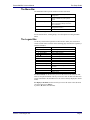
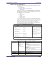
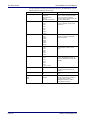
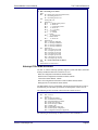
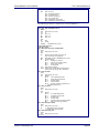
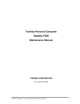
If you need to change your drive settings, selecting one of the Master or Slave
drives on the Main Menu displays a sub-menu like this:
PhoenixBIOS Setup Utility
Main
Primary Master
Type:
Cylinders:
Heads:
Sectors/Track:
Maximum Capacity:
[Auto]
[ 13328]
[ 15]
[ 63]
6449 MB
Landing Zone:
Write Precomp:
[ 762]
[None]
Multi Sector Transfer;
LBA Mode Control:
32-bit I/O:
Transfer Mode:
SMART Monitoring
[16 Sectors]
[Enabled]
[Enabled]
[Fast PIO 4]
[Enabled]
F1 Help
ESC Exit
¦ Select Item
¥Select Menu
Item Specific Help
Select the drive type of
the fixed disk installed
in your system. If type
User is selected,
Cylinders, Heads, and
Sectors can be edited
directly.
Auto attempts to
automatically detect the
drive type for drives
that comply with ANSI
specifications.
-/+ Change Values
Enter Select
Sub-Menu
F9 Setup Defaults
F10 Save and Exit
Use the legend keys listed on the bottom to make your selections and exit to the
Main Menu. Use the following chart to configure the hard disk.
Feature
Type
Cylinders
Heads
Sectors/Track
Landing Zone*
Phoenix Technologies Ltd.
Options
None
1 to 39
User
Auto
IDE Removable
CD-ROM
ATAPI Removable
1 to 65,536
1 to 16
1 to 63
1 to 2048
Description
None = Autotyping is not able to supply the drive type or
end user has selected None, disabling any drive that may
be installed.
User = You supply the hard-disk drive information in the
following fields.
Auto = Autotyping, the drive itself supplies the correct
drive information.
IDE Removable = Removable read-and-write media (e.g.,
IDE Zip drive).
CD-ROM = Readable CD-ROM drive.
ATAPI Removable = Read-and-writea media (e.g., LS120,
USB Floppy, USB Zip).
Number of cylinders.
Number of read/write heads.
Number of sectors per track.
Number of the cylinder specified as the landing zone for
the read/write heads.
Page 5
The Setup Guide
PhoenixBIOS 4.0 User's Manual
Feature
Write Precomp*
Multi-Sector
Transfers
LBA Mode Control
32-Bit I/O
Transfer Mode
SMART Monitoring
Options
1 to 2048
None
Disabled
Standard
2 sectors
4 sectors
8 sectors
16 sectors
Enabled
Disabled
Enabled
Disabled
Standard
Fast PIO 1
Fast PIO 2
Fast PIO 3
Fast PIO 4
Enabled
Disabled
Description
Number of the cylinder at which to change the write
timing.
Any selection except Disabled determines the number of
sectors transferred per block. Standard is 1 sector per
block.
Enabling LBA causes Logical Block Addressing to be used
in place of Cylinders, Heads, & Sectors.
Enables 32-bit communication between CPU and IDE
card. Requires PCI or local bus.
Selects the method for transferring the data between the
hard disk and system memory.
The Setup menu only lists those options supported by the
drive and platform.
Turn on Self-Monitoring Analysis-Reporting Technology,
which monitors condition of the hard drive and reports
when a catastrophic IDE failure is about to happen.
* IDE drives do not require setting Landing Zone and Write Precomp.
When you enter Setup, the Main Menu usually displays the results of
Autotyping– information each drive provides about its own parameters (e.g.,
cylinders, heads, and sectors)–and how the drives are arranged as Masters or
Slaves on your machine.
Some older drives, however, do not use Autotyping and require selecting type
User and entering a pre-defined fixed-disk type value (e.g., 1 to 39) or specifying
the drive parameters separately with the User type selected. You can find the
correct parameters for hard-disk drives in the drive manual or written on the
casing of the drive itself.
Note: Exiting this menu keeps your selections but loses internal autotyping
information, which may not be selected. If you exit this menu and re-enter it,
press <Enter> on Autotype again to restore the Autotype information.
Note: Do not attempt to change these settings unless you have an older drive that
does not support autotyping.
Note: Before changing the contents of this menu, write them down. Once you
have established correct parameters for your drive, write them down and store
them in a safe place (e.g., tape them to the disk drive) for use in case these
values are lost in CMOS or if autotyping fails. If these hard-disk parameters are
not correctly entered in CMOS, you cannot access the data on your drive.
WARNING: Incorrect settings can cause your system to malfunction. To correct
mistakes, return to Setup and restore the Setup Defaults with <F9> and re-enter
the correct drive parameters.
Page 6
Phoenix Technologies Ltd.
PhoenixBIOS 4.0 User's Manual
The Setup Guide
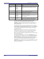
Memory Cache
Enabling cache saves time for the CPU by holding data most recently accessed
in regular memory (dynamic RAM or DRAM) in a special storage area of static
RAM (SRAM), which is faster. Before accessing regular memory, the CPU first
accesses the cache. If it does not find the data it is looking for there, it accesses
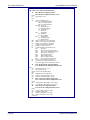
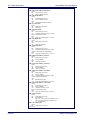
regular memory. Selecting "Memory Cache" from the Main menu displays a
menu like the one shown here. The actual features displayed depend on your
system's hardware.
PhoenixBIOS Setup Utility
Main
Memory Cache
External cache:
[Enabled]
Cache Interleave:
Cache Write Back:
Cache Read Cycles:
[Disabled]
[Disabled]
[2T]
Cache
Cache
Cache
Cache
Cache
Cache
Cache
Cache
[Disabled]
[Enabled]
[Disabled]
[Disabled]
[Disabled]
[Disabled]
[Disabled]
[Disabled]
System BIOS:
Video BIOS:
E800 - EFFF:
E000 - E7FF:
D800 - DFFF:
D000 - D7FF:
C800 - CFFF:
C800 - CFFF:
Item Specific Help
Sets the state of the
external system memory
cache.
Non-cacheable Regions
Region 0, start: [
0 kB]
Region 0, size:
[Disabled]
Region 1, start: [
0 kB]
Region 1, size:
[Disabled]
F1 Help
ESC Exit
¦ Select Item
¥Select Menu
-/+ Change Values
Enter Select
Sub-Menu
F9 Setup Defaults
F10 Save and Exit
Use the legend keys listed on the bottom to make your selections and exit to the
Main Menu. Use this chart to configure the memory cache.
Feature
External Cache
Cache Interleave
Cache Write Back
Cache Read Cycles
Cache Write Cycles
Cache System BIOS
Cache Video BIOS
Cache segments, e.g., E800-EFFF
Non-cacheable regions:
Region 0, start
Region 0, size
Region 1, start
Region 1, size
Options
Enabled
Disabled.
Enabled
Disabled
Enabled
Disabled
Chipset
Dependent
Chipset
Dependent
Enabled
Disabled
Enabled
Disabled
Enabled
Disabled
0
Multiples of 64
Disabled
Multiples of 64
0
Multiples of 64
Disabled
Multiples of 64
Description
Generally enables or disables all memory caching.
Interleaves multiple banks of static RAM. Improves CPU access.
Enables caches to both read and write to memory. Disabled caches reads
only.
Sets the number of clock pulses for reading from the cache. Shorter number
of pulses improves performance.
Sets the number of clock pulses for writing to the cache. Shorter number of
pulses improves performance.
Caches the system BIOS and improves performance.
Caches the video BIOS and improves performance.
Controls caching of individual segments of memory usually reserved for
shadowing system or option ROMs
Specifies areas of regular and extended memory as non-cacheable regions.
Multiples of 64 define start of non-cacheable region 0 in kilobytes.
Disabling makes this region available for cache. Multiples of 64 define size
of non-cacheable region 0 in kilobytes.
Multiples of 64 define start of non-cacheable region 1 in kilobytes.
Disabling makes this region available for cache. Multiples of 64 define size
of non-cacheable region 1 in kilobytes.
WARNING: Incorrect settings can cause your system to malfunction. To correct
mistakes, return to Setup and restore the Setup Defaults with <F9>.
Phoenix Technologies Ltd.
Page 7
The Setup Guide
PhoenixBIOS 4.0 User's Manual
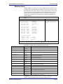
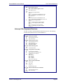
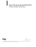
Memory Shadow
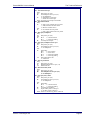
Selecting "System Shadow" or "Video Shadow" from the Main Menu displays a
menu like the one shown here. The actual features displayed depend on the
capabilities of your system's hardware.
PhoenixBIOS Setup Utility
Main
Memory Shadow
System shadow:
Video shadow:
Item Specific Help
Enabled
[Enabled]
Enables shadowing of
Option ROM in this
region.
Shadow Option ROM's –
C800 - CFFF:
[Disable]
D000 - D7FF:
[Disable]
D800 - DFFF:
[Disable]
D800 - DFFF:
[Disable]
E800 - EFFF:
[Disable]
F1 Help
ESC Exit
¦ Select Item
¥Select Menu
-/+ Change Values
Enter Select
Sub-Menu
F9 Setup Defaults
F10 Save and Exit
Use the legend keys to make your selections and exit to the Main Menu. Use the
following chart to configure memory shadowing.
WARNING: Incorrect settings can cause your system to malfunction. To correct
mistakes, return to Setup and restore the Setup Defaults with <F9>.
Feature
System shadow
Video shadow
Shadow Option
ROM
Page 8
Options
N/A
Enabled
Disabled
Enabled
Disabled
Description
Usually permanently enabled.
Shadows video BIOS and improves
performance.
Shadows option ROM located in the
specified segments of memory and
can improve performance.
WARNING: Some option ROMs do
not work properly when shadowed.
Phoenix Technologies Ltd.
PhoenixBIOS 4.0 User's Manual
The Setup Guide
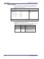
Boot Sequence
Selecting "Boot Sequence" on the Main Menu displays the Boot Options menu.
PhoenixBIOS Setup Utility
Main
Boot Options
Boot sequence:
SETUP prompt:
POST Errors:
Floppy check:
Summary screen:
F1 Help
ESC Exit
Item Specific Help
[Disabled]
[Enabled]
[Enabled]
[Enabled]
[Enabled]
¦ Select Item
¥Select Menu
Order in which the
system searches for a
boot disk.
-/+ Change Values
Enter Select
Sub-Menu
F9 Setup Defaults
F10 Save and Exit
Use the legend keys to make your selections and exit to the Main Menu.
Use the following chart to select your boot options.
Feature
Boot sequence
Options
A: then C;
C: then A:
C: only
Setup prompt
Enabled
Disabled
Enabled
Disabled
POST errors
Phoenix Technologies Ltd.
Floppy seek
Enabled
Disabled
Summary screen
Enabled
Disabled
Description
The BIOS attempts to load the
operating system from the disk
drives in the sequence selected
here. See also the Boot Menu
on p. 11.
Displays "Press <F2> for
Setup" during boot up.
At boot error, pauses and
displays "Press <F1> to
resume, <F2> to Setup".
Seeks diskette drives during
boot up. Disabling speeds boot
time.
Displays system summary
screen during boot up.
Page 9
The Setup Guide
PhoenixBIOS 4.0 User's Manual
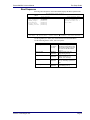
Keyboard Features
Selecting "Numlock" on the Main Menu displays the Keyboard Features menu:
PhoenixBIOS Setup Utility
Main
Keyboard Features
Numlock:
Key Click:
Keyboard auto-repeat rate:
Keyboard auto-repeat delay:
F1 Help
ESC Exit
¦ Select Item
¥Select Menu
Item Specific Help
[Off]
[Disabled]
[30/sec]
[1/2 sec]
Selects power-on state
for Numlock key.
-/+ Change Values
Enter Select
Sub-Menu
F9 Setup Defaults
F10 Save and Exit
Use the legend keys to make your selections and exit to the Main Menu.
Use the following chart to configure the keyboard features:
Feature
Numlock
Key Click
Keyboard auto-repeat rate
Keyboard auto-lag delay
Page 10
Options
Auto
On
Off
Enabled
Disabled
2/sec
6/sec
10/sec
13.3/sec
21.8/sec
26.7/sec
30/sec
¼ sec
½ sec
¾ sec
1 sec
Description
On or Off turns NumLock on or
off at boot up. Auto turns
NumLock on if it finds a
numeric key pad.
Turns audible key click on.
Sets the number of times a
second to repeat a keystroke
when you hold the key down.
Sets the delay time after the key
is held down before it begins to
repeat the keystroke.
Phoenix Technologies Ltd.
PhoenixBIOS 4.0 User's Manual
The Setup Guide
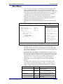
Boot Menu
After you turn on your computer, it will attempt to load the operating system
(such as Windows 98) from the device of your choice. If it cannot find the
operating system on that device, it will attempt to load it from one or more other
devices in the order specified in the Boot Menu. Boot devices (i.e., with access
to an operating system) can include: hard drives, floppy drives, CD ROMs,
removable devices (e.g., Iomega Zip drives), and network cards.
Note: Specifying any device as a boot device on the Boot Menu requires the
availability of an operating system on that device. Most PCs come with an
operating system already installed on hard-drive C:.
Selecting "Boot" from the Menu Bar displays the Boot menu, which looks like
this:
Main
PhoenixBIOS Setup Utility
Advanced
Security
Power
Boot
QuickBoot Mode:
Display OPROM Messages:
Preferred Video:
Summary Screen:
[Enabled]
[Enabled]
[AGP]
[Enabled]
Use these keys to set
the boot order in which
the BIOS attempts to
boot the OS:
<+> or <-> moves device
up or down.
<Enter> expands or
collapses devices marked
with + or -.
<Ctrl+Enter> expands all
<Shift+1> enables or
disables a device.
<n> moves a removable
device between hard or
removable disk.
Removable Devices
ATAPI CD-ROM Drive
-Hard Drive
Primary Master
Bootable Add-in Card
Network Boot
F1 Help
ESC Exit
¦ Select Item
¥Select Menu
Exit
Item Specific Help
-/+ Change Values
Enter Select
Sub-Menu
F9 Setup Defaults
F10 Save and Exit
Use this menu to arrange to specify the priority of the devices from which the
BIOS will attempt to boot the Operating System. In the example above, the
BIOS will attempt first to boot from the CD-ROM drive (the only Removable
Device listed). Failing that, it will attempt to boot from the Primary Master hard
disk, and so on down the list.
Removable Devices, Hard Drive, and Network Boot are the generic types of
devices on your system from which you can boot an operating system. You may
have more than one device of each type. If so, the generic type is marked with a
plus or minus sign. Use the <Enter> key to expand or collapse the devices
marked with <+> or <->. Press <Ctrl+Enter> to expand all such devices.
Note: Floppy drives are not managed on this menu as part of Removable
Devices.
To change a device’s priority on the list, first select it with the up-or-down
arrows, and move it up or down using the <+> and <-> keys. Pressing <n>
moves a device between the Removable Devices and Hard Drive. Pressing
<Shift+1> enables or disables a device.
Feature
QuickBoot Mode
Display OPROM Messages
Preferred Video
Summary Screen
Phoenix Technologies Ltd.
Options
Enabled
Disabled
Enabled
Disabled
AGP
PCI
Enabled
Disabled
Description
Enabled skips some POST tests,
speeding boot time
Displays boot messages of add-on
cards. Recommended for newly
installed cards. May be disabled later.
If you have more than one video card,
select one to be used at boot.
Display system configuration screen
during POST.
Page 11
The Setup Guide
PhoenixBIOS 4.0 User's Manual
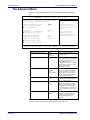
The Advanced Menu
Selecting "Advanced" from menu bar on the Main Menu displays a menu like
this:
Main
PhoenixBIOS Setup Utility
Advanced
Security
Power
Boot
Exit
Item Specific Help
Setting items on this menu to incorrect values
may cause your system to malfunction.
Installed Operating System
Reset Configuration Data:
PCI Configuration
[Other]
[No]
PS/2 Mouse
Secured Setup Configurations
Peripheral Configuration
[Enabled]
[No]
Large Disk Access Mode:
Local Bus IDE adapter:
SMART Device Monitoring:
[DOS]
[Both]
[Enabled]
Advanced Chipset Control
I/O Device Configuration
F1 Help
¦ Select Item
ESC Exit
¥Select Menu
Select the operating
system installed on you
system that you use most
often.
Note: An incorrect
setting can cause
unexpected behavior in
some operating systems.
-/+ Change Values
Enter Select
Sub-Menu
F9 Setup Defaults
F10 Save and Exit
Use the legend keys to make your selections and exit to the Main Menu.
Feature
Installed Operating System
Reset Configuration Data
Options
Other
Win95
Win98/NT
Yes
No
PS/2 Mouse
Enabled
Disabled
Auto
OS Controlled
Secured Setup Configurations
Yes
No
Large Disk Access Mode
DOS
Other
SMART
Enabled
Disabled
Description
Select the operating system you
use most often.
Yes erases all configuration data
in a section of memory for ESCD
(Extended System Configuration
Data) which stores the
configuration settings for non-PnP
plug-in devices. Select Yes when
required to restore the
manufacturer's defaults.
Disabled disables any installed
PS/2 mouse, but frees up IRQ 12
for use by another device. Auto
lets the BIOS control the mouse.
OS Controlled lets the operating
system control the mouse.
Yes prevents the Operating
System from overriding selections
you have made in Setup.
Select DOS if you have DOS.
Select Other if you have another
operating system such as UNIX.
A large disk is one that has more
than 1024 cylinders, more than 16
heads, or more than 63 tracks per
sector.
Enabled installs SMART (SelfMonitoring Analysis-Reporting
Technology), which issues a
warning if an IDE failure is
imminent.
WARNING: Incorrect settings can cause your system to malfunction. To correct
mistakes, return to Setup and restore the Setup Defaults with <F9>.
Page 12
Phoenix Technologies Ltd.
PhoenixBIOS 4.0 User's Manual
The Setup Guide
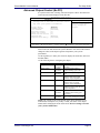
Advanced Chipset Control (No PCI)
In a system with no PCI, selecting "Advanced Chipset Control" from menu bar
on the Advanced menu displays a menu like this:
PhoenixBIOS Setup Utility
Advanced
Warning!
Item Specific Help
Setting items on this menu to incorrect values
may cause your system to malfunction.
Controls system memory
parity through the
Parity check:
[Enabled]
chipset.
Hidden refresh:
[Enabled]
Slow refresh:
[Disabled]
Read wait states:
[0]
Write wait states:
[0]
Extra bus wait states: [0]
Multiple ALE:
[Enabled]
Keyboard reset delay:
[Disabled]
F1 Help
ESC Exit
¦ Select Item
¥Select Menu
-/+ Change Values
Enter Select
Sub-Menu
F9 Setup Defaults
F10 Save and Exit
The chipset consists of one or more integrated circuits that act as an interface
between the CPU and much of the system's hardware. You can use this menu to
change the values in the chipset registers and optimize your system's
performance. .
Use the legend keys to make your selections, display the sub menus, and exit to
the Main Menu.
Use the following chart in configuring the chipset:
Feature
Parity check
Read wait states
Options
Enabled
Disabled
Enabled
Disabled
Enabled
Disabled
0 to n
Write wait states
0 to n
Extra bus wait states
0 to n
Multiple ALE
Enabled
Disabled
Keyboard reset delay
Enabled
Disabled
Hidden refresh
Slow Refresh
Description
Controls system memory parity
checking.
Refreshes regular memory
without holding up the CPU.
Slows memory refresh by a factor
of 4.
Sets the number of wait states
added to reads from system
memory. Chipset dependent.
Sets the number of wait states
added to writes to system
memory. Chipset dependent.
Sets the number of wait states
added to accesses of the AT bus.
Chipset dependent.
Determines whether to use single
or multiple ALEs during cycle
conversion.
Enabled adds a 2 microsecond
delay before resetting the system.
NOTE: The contents of this menu depend on the chipset installed on your
motherboard, and chipsets vary widely. Consult your dealer or the chipset
manual before changing the items on this menu. Incorrect settings can cause
your system to malfunction.
Phoenix Technologies Ltd.
Page 13
The Setup Guide
PhoenixBIOS 4.0 User's Manual
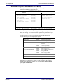
Advanced Chipset Control Menu (PCI BIOS)
If the system has a PCI chipset, selecting "Advanced Chipset Control" from the
Advanced menu displays a menu like this:
PhoenixBIOS Setup Utility
Advanced
Advanced Chipset Control
Hidden Refresh:
Code Read Page Mode:
Write Page Mode:
CPU to PCI Write Buffers:
PCI to DRAM Write Buffers:
CPU to DRAM Write Buffers:
Snoop Ahead:
PCI Memory Burst Cycles:
F1 Help
ESC Exit
[Disabled]
[Disabled]
[Disabled]
[Disabled]
[Disabled]
[Disabled]
[Disabled]
[Disabled]
¦ Select Item
¥Select Menu
Item Specific Help
Enables CPU to PCI write
buffers, which allow
data to be temporarily
stored in buffers before
writing the data.
-/+ Change Values
Enter Select
Sub-Menu
F9 Setup Defaults
F10 Save and Exit
The chipset is one or more integrated circuits that act as an interface between the
CPU and the system's hardware. It manages such things as memory access,
buses, and caching. You can use this menu to optimize the performance of your
computer.
Use the legend keys to make your selections and exit to the Main Menu.
Use the following chart in configuring the chipset:
Feature
Hidden Refresh
Code Read Page Mode
Write Page Mode
CPU to PCI Write Buffers
PCI to DRAM Write Buffers
CPU to DRAM Write Buffers
Snoop Ahead
PCI Memory Burst Cycles
Options
Disabled
Enabled
Disabled
Enabled
Disabled
Enabled
Disabled
Enabled
Disabled
Enabled
Disabled
Enabled
Disabled
Enabled
Disabled
Enabled
Description
Refreshes regular memory
without holding up the CPU
Improves performance when
code contains mainly sequential
instructions.
Improves performance when data
is written sequentially.
Stores CPU data in buffers
before writing to PCI.
Stores PCI data in buffers before
writing to DRAM.
Stores CPU data in buffers
before writing to DRAM.
Improves PCI bus master access
to DRAM.
Enables PCI memory burst write
cycles.
NOTE: The contents of this menu depend on the chipset installed on your
motherboard, and chipsets vary widely. Consult your dealer or the computer
manual before changing the items on this menu. Incorrect settings can cause
your system to malfunction.
Page 14
Phoenix Technologies Ltd.
PhoenixBIOS 4.0 User's Manual
The Setup Guide
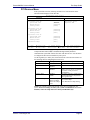
PCI Devices Menu
If the system has a PCI bus, selecting "PCI Devices" from menu bar on the
Advanced menu displays a menu like this:
PhoenixBIOS Setup Utility
Advanced
PCI Devices
PCI Device Slot #1:
Option ROM Scan:
Enable Master:
Latency Timer:
[Enabled]
[Disabled]
[0040h]
PCI Device Slot #2:
Option ROM Scan:
Enable Master:
Latency Timer:
[Disabled]
[Disabled]
[0000]
PCI Device Slot #3
Option ROM Scan:
Enable Master:
Latency Timer:
[Disabled]
[Disabled]
[0000]
Shared PCI IRQs:
[Auto]
F1 Help
ESC Exit
¦ Select Item
¥Select Menu
Item Specific Help
Initialize device
expansion ROM
-/+ Change Values
Enter Select
Sub-Menu
F9 Setup Defaults
F10 Save and Exit
PCI Devices are devices equipped for operation with a PCI (Peripheral
Component Interconnect) bus, a standardized Plug-and-Play hardware
communication system that connects the CPU with other devices. Use this menu
to configure the PCI devices installed on your system.
Use the legend keys to make your selections and exit to the Advanced menu. Use
the following chart in configuring the PCI devices:
Feature
PCI Device Slots 1-n:
Option ROM Scan
Enable Master
Options
Disabled
Enabled
Disabled
Enabled
Latency Timer
0000h to
0280h
Shared PCI IRQs
Share One IRQ
Share Two IRQs
Share Three IRQs
Auto
Description
Initialize device expansion ROM.
Enables selected device as a PCI bus
master. Not every device can function
as a master. Check your device
documentation.
Bus master clock rate. A high-priority,
high-throughput device may benefit
from a greater value.
Share n IRQs: Forces PCI devices to
use at most n IRQs.
Auto: Minimizes PCI IRQ Sharing.
NOTE: The contents of this menu depend on the devices installed on your
system. Incorrect settings can cause your system to malfunction. To correct
mistakes, return to Setup and restore the System Defaults (F9).
Phoenix Technologies Ltd.
Page 15
The Setup Guide
PhoenixBIOS 4.0 User's Manual
I/O Device Configuration Menu
The CPU communicates with external devices such as printers through devices
called Input/Output (I/O) ports such as serial and parallel ports. These I/O
devices require the use of system resources such as I/O addresses and interrupt
lines. If these devices are Plug and Play, either the BIOS can allocate the devices
during POST, or the operating system can do it. If the I/O devices are not Plug
and Play, they may require manually setting them in Setup.
On some systems, the chipset manages the communication devices. Other
systems have, instead, a separate I/O chip on the motherboard for configuring
and managing these devices.
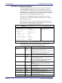
Many systems allow you to control the configuration settings for the I/O ports.
Select "I/O Device Configuration" on the Advanced Menu to display this menu
and specify how you want to configure these I/O Devices:
PhoenixBIOS Setup Utility
Advanced
I/O Device Configuration
Serial Port A:
Base I/O address/IRQ
Serial Port B:
Parallel Port:
Mode:
Base I/O address
Interrupt
[Enabled]
[3F8/IRQ4]
[OS Controlled]
[User]
[Bi-directional]
[378]
[IRQ5]
Diskette Controller
Base I/O address:
[Enabled]
[Primary]
Legacy USB Support:
[Enabled]
¦Select Item
¥Select Menu
F1 Help
ESC Exit
Item Specific Help
Enable support for
Legacy Universal Serial
Bus
-/+ Change Values
Enter Select
Sub-Menu
F9 Setup Defaults
F10 Save and Exit
Use the legend keys to make your selections and exit to the Main Menu.
Use the following chart to configure the Input/Output settings:
Options
Description
Serial port A:
Serial port B:
Feature
Disabled
Enabled
Auto
OS Controlled
Base I/O Address/IRQ
3F8, IRQ 4
2F8, IRQ 3
Disabled
Enabled
Auto
OS Controlled
Disabled turns off the port.
Enabled requires you to enter the base Input/Output address
and the Interrupt number on the next line.
Auto makes the BIOS configure the port automatically during
POST.
OS Controlled lets the PnP Operating System (such as
Windows 95) configure the port after POST.
If you select Enabled, choose one of these combinations.
Parallel Port:
Mode
Output only
Bi-directional
Base I/O Address
378
278
3BC
IRQ5
IRQ7
Disabled
Enabled
Primary
Secondary
Interrupts
Diskette Controller
Base I/O Address
Legacy USB Support
Page 16
Enabled
Disabled
Disabled turns off the port.
Enabled requires you to enter the base Input/Output address
and the Interrupt number below.
Auto makes the BIOS auto configure the port during POST.
OS Controlled lets the PnP Operating System (such as
Windows 95) configure the port after POST.
Output only is standard one-way protocol for a parallel
device.
Bi-directional uses two-way protocol of an Extended
Capabilities Port (ECP).
If you select Enabled for the Parallel Port, choose one of
these I/O addresses.
If you select Enabled for the Parallel Port, choose one of
these interrupt options.
Enables the on-board legacy diskette controller.
Disabled turns off all legacy diskette drives.
If you select Enabled for the Diskette Controller, choose
Primary for one diskette drive installed or Secondary for two
diskette drives installed.
Enables support for legacy USB bus.
Phoenix Technologies Ltd.
PhoenixBIOS 4.0 User's Manual
The Setup Guide
Use this menu to specify how the I/O (Input and Output) ports are configured:
• Manually by you.
• Automatically by the BIOS during POST (See "ROM BIOS Functions"
on page 32)
• Automatically by a PnP Operating System such as Windows 95 after the
Operating System boots.
Warning: If you choose the same I/O address or Interrupt for more than one port, the
menu displays an asterisk (*) at the conflicting settings. It also displays this message at
the bottom of the menu:
* Indicates a DMA, Interrupt, I/O, or memory resource
conflict with another device.
Resolve the conflict by selecting another settings for the devices.
Phoenix Technologies Ltd.
Page 17
The Setup Guide
PhoenixBIOS 4.0 User's Manual
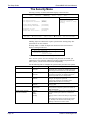
The Security Menu
Selecting "Security" from the Main Menu displays a menu like this:
Main
PhoenixBIOS Setup Utility
Advanced
Security
Power
Boot
Set User Password
Set Supervisor Password
[Enter]
[Enter]
Virus Check Reminder:
System backup Reminder:
[Disabled]
[Disabled]
Password on boot:
Diskette access:
Fixed disk boot sector:
[Disabled]
[Disabled]
[Normal]
F1 Help
ESC Exit
¦ Select Item
¥Select Menu
Exit
Item Specific Help
Supervisor password
controls access to Setup
utility.
-/+ Change Values
Enter Select
Sub-Menu
F9 Setup Defaults
F10 Save and Exit
Use the legend keys to make your selections and exit to the Main Menu.
Enabling "Supervisor Password" requires a password for entering Setup. The
passwords are not case sensitive.
Pressing <Enter> at either Set Supervisor Password or Set User Password
displays a dialog box like this:
Set Password
Enter new password: [
Confirm new password: [
Enter: Accept
]
]
Type the password and press <Enter>. Repeat.
Note: In some systems, the User and Supervisor passwords are related; you
cannot have a User password without first creating a Supervisor password. In
other systems, you can create and use them independently.
Use the following chart to configure the system-security and anti-virus options.
Feature
Set User Password
Options
Up to seven alphanumeric
characters
Set Supervisor Password
Up to seven alphanumeric
characters
Password on boot
Enabled
Disabled
Diskette access
Enabled
Disabled
Normal
Write Protect
Fixed disk boot sector
System backup reminder
Virus check reminder
Page 18
Disabled
Daily
Weekly
Monthly
Description
Pressing <Enter> displays the dialog box for
entering the user password. In related systems, this
password gives restricted access to SETUP menus.
Pressing <Enter> displays dialog box for entering
the supervisor password. In related systems, this
password gives full access to Setup menus.
Enabled requires a password on boot. Requires prior
setting of the Supervisor password.
If supervisor password is set and this option
disabled, BIOS assumes user is booting.
Enabled requires a password to boot from or access
the floppy disk.
Write protects the boot sector on the hard disk for
virus protection. Requires a password to format or
Fdisk the hard disk.
Displays a message during boot up asking (Y/N) if
you have backed up the system or scanned it for
viruses.
Message returns on each boot until you respond with
"Y".
Daily displays the message on the first boot of the
day, Weekly on the first boot after Sunday, and
Monthly on the first boot of the month.
Phoenix Technologies Ltd.
PhoenixBIOS 4.0 User's Manual
The Setup Guide
The Power Menu
Selecting "Power" from the menu bar displays a menu like this:
Main
PhoenixBIOS Setup Utility
Advanced
Security
Power
Boot
Power Savings
[Customize]
Standby Timeout:
Auto Suspend Timeout:
[15 sec]
[15 sec]
Hard Disk Timeout:
Video Timeout:
[10 min]
[ 5 min]
Resume On Modem Ring:
Resume On Time:
[Off]
[Off]
Select Power Management
Mode. Choosing modes
changes system power
management settings.
Maximum Power Savings
conserves the greatest
amount of system power
while Maximum
Performance conserves
power but allows
greatest system
performance. To alter
these settings, choose
Customize. To turn off
power management, choose
Disable.
Advanced Options
F1 Help
ESC Exit
¦ Select Item
¥Select Menu
Exit
Item Specific Help
-/+ Change Values
Enter Select
Sub-Menu
F9 Setup Defaults
F10 Save and Exit
Use this menu to specify your settings for Power Management. Remember that
the options available depend upon the hardware installed in your system. Those
shown here are from a typical system.
A power-management system reduces the amount of energy used after specified
periods of inactivity. The Setup menu pictured here supports a Full On state, a
Standby state with partial power reduction, and a Suspend state with full power
reduction.
Use the Advanced Options on this menu to specify whether or not the activity of
interrupts can terminate a Standby or Suspend state and restore Full On. Do not
change these settings without knowing which devices use the interrupts.
Phoenix Technologies Ltd.
Page 19
The Setup Guide
PhoenixBIOS 4.0 User's Manual
Use the legend keys to make your selections and exit to the Main Menu. Use the
following chart in making your selections:
Feature
Power Management Mode
Standby Timeout
Auto Suspend Timeout
Hard Disk Timeout
Video Timeout
Resume On Modem Ring
Resume On Time
IRQ0...IRQ15
SMI
NMI
Page 20
Options
Disabled
Customize
Maximum Power
Savings
Maximum Performance
Off
1 min
2 min
4 min
6 min
8 min
12 min
16 min
Disabled
5 min
10 min
15 min
20 min
30 min
40 min
60 min
Disabled
1 min
2 min
4 min
8 min
12 min
16 min
Disabled
10 sec
15 sec
20 sec
30 sec
45 sec
1 min to 15 min
Off
On
Off
On
Disabled
Enabled
Description
Maximum options: pre-defined
values. Select Customize to make
your own selections from the
following fields. Disabled turns off
all power management.
Inactivity period required to put
system in Standby (partial power
shutdown).
Inactivity period required after
Standby to Suspend (maximum
power shutdown).
Inactivity period of hard disk
required before standby (motor
off).
Set inactivity period required
before independently turning off
monitor. Disabled turns CRT off in
Standby.
Wakes up system when an
incoming call is detected on the
modem.
Wakes up system at predetermined
time.
Enabling interrupt causes it to
restore Full On during Standby or
Suspend. SMI = System
Management Interrupt. NMI =
Non-Maskable Interrupt.
Phoenix Technologies Ltd.
PhoenixBIOS 4.0 User's Manual
The Setup Guide
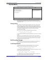
The Exit Menu
Selecting "Exit" from the menu bar displays this menu:
Main
PhoenixBIOS Setup Utility
Advanced
Security
Power
Boot
Exit Saving Changes
Exit Discarding Changes
Load Setup Defaults
Discard Changes
Save Changes
F1 Help
ESC Exit
¦ Select Item
¥Select Menu
Exit
Item Specific Help
Exit System Setup and
save your changes to
CMOS.
-/+ Change Values
Enter Select
Sub-Menu
F9 Setup Defaults
F10 Save and Exit
The following sections describe each of the options on this menu. Note that
<Esc> does not exit this menu. You must select one of the items from the menu
or menu bar to exit.
Saving Values
After making your selections on the Setup menus, always select either "Saving
Values" or "Save Changes." Both procedures store the selections displayed in
the menus in CMOS (short for "battery-backed CMOS RAM") a special section
of memory that stays on after you turn your system off. The next time you boot
your computer, the BIOS configures your system according to the Setup
selections stored in CMOS.
After you save your selections, the program displays this message:
Values have been saved to CMOS!
Press <space> to continue
If you attempt to exit without saving, the program asks if you want to save before
exiting.
During boot up, PhoenixBIOS attempts to load the values saved in CMOS. If
those values cause the system boot to fail, reboot and press <F2> to enter Setup.
In Setup, you can get the Default Values (as described below) or try to change
the selections that caused the boot to fail.
Exit Discarding Changes
Use this option to exit Setup without storing in CMOS any new selections you
may have made. The selections previously in effect remain in effect.
Load Setup Defaults
To display the default values for all the Setup menus, select "Load Setup
Defaults" from the Main Menu. The program displays this message:
ROM Default values have been loaded!
Press <space> to continue
If, during boot up, the BIOS program detects a problem in the integrity of values
stored in CMOS, it displays these messages:
System CMOS checksum bad - run SETUP
Press <F1> to resume, <F2> to Setup
The CMOS values have been corrupted or modified incorrectly, perhaps by an
application program that changes data stored in CMOS.
Phoenix Technologies Ltd.
Page 21
The Setup Guide
PhoenixBIOS 4.0 User's Manual
Press <F1> to resume the boot or <F2> to run Setup with the ROM default
values already loaded into the menus. You can make other changes before saving
the values to CMOS.
Discard Changes
If, during a Setup Session, you change your mind about changes you have made
and have not yet saved the values to CMOS, you can restore the values you
previously saved to CMOS.
Selecting “Discard Changes” on the Exit menu updates all the selections and
displays this message:
CMOS values have been loaded!
Press <space> to continue
Save Changes
Selecting “Save Changes” saves all the selections without exiting Setup. You can
return to the other menus if you want to review and change your selections.
Page 22
Phoenix Technologies Ltd.
PhoenixBIOS 4.0 User's Manual
The Setup Guide
PhoenixBIOS Messages
The following is a list of the messages that the BIOS can display. Most of them
occur during POST. Some of them display information about a hardware device,
e.g., the amount of memory installed. Others may indicate a problem with a
device, such as the way it has been configured. Following the list are
explanations of the messages and remedies for reported problems.
*If your system displays one of the messages marked below with an asterisk (*),
write down the message and contact your dealer. If your system fails after you
make changes in the Setup menus, reset the computer, enter Setup and install
Setup defaults or correct the error.
0200 Failure Fixed Disk
Fixed disk is not working or not configured properly. Check to see if fixed
disk is attached properly. Run Setup. Find out if the fixed-disk type is
correctly identified.
0210 Stuck key
Stuck key on keyboard.
0211 Keyboard error
Keyboard not working.
*0212 Keyboard Controller Failed
Keyboard controller failed test. May require replacing keyboard controller.
0213 Keyboard locked - Unlock key switch
Unlock the system to proceed.
0220 Monitor type does not match CMOS - Run SETUP
Monitor type not correctly identified in Setup
*0230 Shadow Ram Failed at offset: nnnn
Shadow RAM failed at offset nnnn of the 64k block at which the error
was detected.
*0231 System RAM Failed at offset: nnnn
System RAM failed at offset nnnn of in the 64k block at which the error
was detected.
*0232 Extended RAM Failed at offset: nnnn Extended memory not
working or not configured properly at offset nnnn.
0250 System battery is dead - Replace and run SETUP
The CMOS clock battery indicator shows the battery is dead. Replace the
battery and run Setup to reconfigure the system.
0251 System CMOS checksum bad - Default configuration used
System CMOS has been corrupted or modified incorrectly, perhaps by an
application program that changes data stored in CMOS. The BIOS
installed Default Setup Values. If you do not want these values, enter Setup
and enter your own values. If the error persists, check the system battery
or contact your dealer.
*0260 System timer error
The timer test failed. Requires repair of system board.
*0270 Real time clock error Real-Time Clock fails BIOS hardware test.
May require board repair.
0271 Check date and time settings BIOS found date or time out of
range and reset the Real-Time Clock. May require setting legal date (19912099).
0280 Previous boot incomplete - Default configuration used
Previous POST did not complete successfully. POST loads default values
and offers to run Setup. If the failure was caused by incorrect values and
they are not corrected, the next boot will likely fail. On systems with
control of wait states, improper Setup settings can also terminate POST
and cause this error on the next boot. Run Setup and verify that the waitstate configuration is correct. This error is cleared the next time the system
is booted.
0281 Memory Size found by POST differed from CMOS
Memory size found by POST differed from CMOS.
02B0 Diskette drive A error
02B1 Diskette drive B error
Drive A: or B: is present but fails the BIOS POST diskette tests. Check to
Phoenix Technologies Ltd.
Page 23
The Setup Guide
PhoenixBIOS 4.0 User's Manual
see that the drive is defined with the proper diskette type in Setup and that
the diskette drive is attached correctly.
02B2 Incorrect Drive A type - run SETUP
Type of floppy drive A: not correctly identified in Setup.
02B3 Incorrect Drive B type - run SETUP
Type of floppy drive B: not correctly identified in Setup.
02D0 System cache error - Cache disabled
RAM cache failed and BIOS disabled the cache. On older boards, check
the cache jumpers. You may have to replace the cache. See your dealer. A
disabled cache slows system performance considerably.
02F0: CPU ID:
CPU socket number for Multi-Processor error.
*02F4: EISA CMOS not writeable
ServerBIOS2 test error: Cannot write to EISA CMOS.
*02F5: DMA Test Failed
ServerBIOS2 test error: Cannot write to extended DMA (Direct Memory
Access) registers.
*02F6: Software NMI Failed
ServerBIOS2 test error: Cannot generate software NMI (Non-Maskable
Interrupt).
*02F7: Fail-Safe Timer NMI Failed
ServerBIOS2 test error: Fail-Safe Timer takes too long.
device Address Conflict
Address conflict for specified device.
Allocation Error for: device
Run ISA or EISA Configuration Utility to resolve resource conflict for the
specified device.
CD ROM Drive
CD ROM Drive identified.
Entering SETUP ...
Starting Setup program
*Failing Bits: nnnn
The hex number nnnn is a map of the bits at the RAM address which failed
the memory test. Each 1 (one) in the map indicates a failed bit. See errors
230, 231, or 232 above for offset address of the failure in System,
Extended, or Shadow memory.
Fixed Disk n
Fixed disk n (0-3) identified.
Invalid System Configuration Data
Problem with NVRAM (CMOS) data.
I/O device IRQ conflict
I/O device IRQ conflict error.
PS/2 Mouse Boot Summary Screen:
PS/2 Mouse installed.
nnnn kB Extended RAM Passed
Where nnnn is the amount of RAM in kilobytes successfully tested.
nnnn Cache SRAM Passed
Where nnnn is the amount of system cache in kilobytes successfully tested.
nnnn kB Shadow RAM Passed
Where nnnn is the amount of shadow RAM in kilobytes successfully
tested.
nnnn kB System RAM Passed
Where nnnn is the amount of system RAM in kilobytes successfully tested.
One or more I2O Block Storage Devices were excluded from
the Setup Boot Menu
There was not enough room in the IPL table to display all installed I2O
block-storage devices.
Operating system not found
Operating system cannot be located on either drive A: or drive C:. Enter
Setup and see if fixed disk and drive A: are properly identified.
*Parity Check 1 nnnn
Parity error found in the system bus. BIOS attempts to locate the address
and display it on the screen. If it cannot locate the address, it displays
????. Parity is a method for checking errors in binary data. A parity error
indicates that some data has been corrupted.
Page 24
Phoenix Technologies Ltd.
PhoenixBIOS 4.0 User's Manual
The Setup Guide
*Parity Check 2 nnnn
Parity error found in the I/O bus. BIOS attempts to locate the address and
display it on the screen. If it cannot locate the address, it displays ????.
Press <F1> to resume, <F2> to Setup,
<F3> for previous
Displayed after any recoverable error message. Press <F1> to start the boot
process or <F2> to enter Setup and change the settings. Press <F3> to
display the previous screen (usually an initialization error of an Option
ROM, i.e., an add-on card). Write down and follow the information shown
on the screen.
Press <F2> to enter Setup
Optional message displayed during POST. Can be turned off in Setup.
PS/2 Mouse:
PS/2 mouse identified.
Run the I2O Configuration Utility
One or more unclaimed block storage devices have the Configuration
Request bit set in the LCT. Run an I2O Configuration Utility (e.g. the SAC
utility).
System BIOS shadowed
System BIOS copied to shadow RAM.
UMB upper limit segment address: nnnn
Displays the address nnnn of the upper limit of Upper Memory Blocks,
indicating released segments of the BIOS which can be reclaimed by a
virtual memory manager.
Video BIOS shadowed
Video BIOS successfully copied to shadow RAM.
Phoenix Technologies Ltd.
Page 25
2
Boot Utilities
Phoenix Boot Utilities are:
• Phoenix QuietBoot™
• Phoenix MultiBoot™
Phoenix QuietBoot displays a graphic illustration rather than the traditional
POST messages while keeping you informed of diagnostic problems.
Phoenix MultiBoot is a boot screen that displays a selection of boot devices
from which you can boot your operating system.
Phoenix QuietBoot
Right after you turn on or reset the computer, Phoenix QuietBoot displays the
QuietBoot Screen, a graphic illustration created by the computer manufacturer
instead of the text-based POST screen, which displays a number of PC
diagnostic messages.
To exit the QuietBoot screen and run Setup, display the MultiBoot menu, or
simply display the PC diagnostic messages, you can simply press one of the hot
keys described below.
The QuietBoot Screen stays up until just before the operating system loads
unless:
1. You press <Esc> to display the POST screen.
2. You press <F2> to enter Setup.
3. POST issues an error message.
4. The BIOS or an option ROM requests keyboard input.
The following explains each of these situations.
Press <ESC>
Pressing <Esc> switches to the POST screen and takes one of two actions:
1. If MultiBoot is installed, the boot process continues with the text-based
POST screen until the end of POST, and then displays the Boot First
Menu, with these options:
a. Load the operating system from a boot device of your choice.
b. Enter Setup.
c. Exit the Boot First Menu (with <Esc>) and load the operating system
from the boot devices in the order specified in Setup.
2. If MultiBoot is not installed, the boot process continues as usual.
Press <F2>
Pressing <F2> at any time during POST switches to the POST screen (if not
already displayed) and enters Setup.
POST Error
Whenever POST detects a non-fatal error, QuietBoot switches to the POST
screen and displays the errors. It then displays this message:
Phoenix Technologies, Ltd.
Page 26
PhoenixBIOS 4.0 User's Manual
Boot Utilities
Press <F1> to resume, <F2> to Setup
Press <F1> to continue with the boot. Press <F2> if you want to correct the error
in Setup.
Keyboard Input Request
If the BIOS or an Option ROM (add-on card) requests keyboard input,
QuietBoot switches over to the POST screen and the Option ROM displays
prompts for entering the information. POST continues from there with the
regular POST screen.
Phoenix MultiBoot
Phoenix MultiBoot expands your boot options by letting you choose your boot
device, which could be a hard disk, floppy disk, or CD ROM. You can select
your boot device in Setup, or you can choose a different device each time you
boot during POST by selecting your boot device in The Boot First Menu.
MultiBoot consists of:
• The Setup Boot Menu
• The Boot First Menu
See the Setup Boot menu on p. 11. The following describes the Boot First Menu.
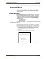
The Boot First Menu
Display the Boot First Menu by pressing <Esc> during POST. In response, the
BIOS first displays the message, "Entering Boot Menu ..." and then displays the
Boot Menu at the end of POST. Use the menu to select any of these options:
1. Override the existing boot sequence (for this boot only) by selecting
another boot device. If the specified device does not load the operating
system, the BIOS reverts to the previous boot sequence.
2. Enter Setup.
3. Press <Esc> to continue with the existing boot sequence.
Boot Menu
Select boot device or Setup.
Use the Up and Down arrows to
select the Boot First device,
then <Enter> or press <Esc> to
exit.
1.
2.
3.
4.
5.
Hard Drive
ATAPI CD-ROM
Diskette Drive
Removable Devices
Network Boot
<Setup>
If there is more than one bootable hard drive, the first one in the Setup Boot
menu is the one represented here.
Phoenix Technologies Ltd.
Page 27
3Phoenix Phlash
Phoenix Phlash gives you the ability to update your BIOS from a floppy disk
without having to install a new ROM BIOS chip.
Phoenix Phlash is a utility for "flashing" (copying) a BIOS to the Flash ROM
installed on your computer from a floppy disk. A Flash ROM is a Read-Only
Memory chip that you can write to using a special method called "flashing." Use
Phoenix Phlash for the following tasks:
Update the current BIOS with a new version.
Restore a BIOS when it has become corrupted.
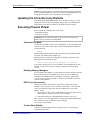
Installation
Phoenix Phlash is shipped on a floppy disk with your computer as a compressed
file called CRISDISK.ZIP that contains the following files:
CRISDISK.BAT
PHLASH.EXE
PLATFORM.BIN
BIOS.ROM
MINIDOS.SYS
MAKEBOOT.EXE
Executable file for creating the Crisis Recovery
Diskette.
Programs the flash ROM.
Performs platform-dependent functions.
Actual BIOS image to be programmed into flash ROM.
Allows the system to boot in Crisis Recovery Mode.
Creates the custom boot sector on the Crisis Recovery
Diskette.
To install Phoenix Phlash on your hard disk, follow this simple procedure:
1. Insert the distribution diskette into drive A:
2. Unzip the contents of CRISDISK.ZIP into a local directory, presumably
C:\PHLASH.
3. Store the distribution diskette in a safe place.
Create the Crisis Recovery Diskette
If the OEM or dealer from whom you purchased your system has not provided
you with one, then you should create a Crisis Recovery Diskette before you use
the Phlash utility. If you are unable to boot your system and successfully load the
Operating System, the BIOS may have been corrupted, in which case you will
have to use the Crisis Recovery Diskette to reboot your system. There are
several methods that you can use to create the Crisis Recovery Diskette. Below
is one recommended procedure.
1. Be sure you have successfully installed the Phlash Utility onto your hard
disk.
2. Insert a clean diskette into drive A: or B:
3. From the local directory, enter the following:
CRISDISK [drive]:
where [drive] is the letter of the drive into which you inserted the diskette.
For help, type /? or /h.
CRISDISK.BAT formats the diskette, then copies MINIDOS.SYS,
VGABIOS.EXE (if available), PHLASH.EXE, PLATFORM.BIN and
BIOS.ROM to the diskette, and creates the required custom boot sector.
Phoenix Technologies, Ltd.
Page 28
PhoenixBIOS 4.0 User's Manual
Boot Utilities
4.
Write protect and label the Crisis Recovery Diskette.
NOTE: You can only supply a volume label after the Crisis Recovery Diskette
has been formatted and the necessary files copied because MINIDOS.SYS must
occupy the first directory entry for the diskette to boot properly.
Updating the Crisis Recovery Diskette
If the BIOS image (BIOS.ROM) changes due to an update or bug fix, you can
easily update the Crisis Recovery Diskette. Simply copy the new BIOS.ROM
image onto the Crisis Recovery Diskette. No further action is necessary.
Executing Phoenix Phlash
You can run Phoenix Phlash in one of two modes:
Command Line Mode
Crisis Recovery Mode
WARNING! For your own protection, be sure you have a Crisis Recovery
Diskette ready to use before executing Phlash.
Command Line Mode
Use this mode to update or replace your current BIOS. To execute Phlash in this
mode, move to the directory into which you have installed Phoenix Phlash and
type the following:
phlash
Phoenix Phlash will automatically update or replace the current BIOS with the
one which your OEM or dealer supplies you.
Phlash may fail if your system is using memory managers, in which case the
utility displays the following message:
Cannot flash when memory managers are present.
If you see this message after you execute Phlash, you must disable the memory
manager on your system. To do so, follow the instructions in the following
sections.
Disabling Memory Managers
To avoid failure when flashing, you must disable the memory managers that load
from CONFIG.SYS and AUTOEXEC.BAT. There are two recommended
procedures for disabling the memory managers. One consists of pressing the
<F5> key (only if you are using DOS 5.0 or above), and the other requires the
creation of a boot diskette.
DOS 5.0 (or later version)
For DOS 5.0 and later, follow the two steps below to disable any memory
managers on your system. If you are not using at least DOS 5.0, then you must
create a boot diskette to bypass any memory managers (See Create a Boot
Diskette, below).
1. Boot DOS 5.0 or later version. (In Windows 95, at the boot option screen,
choose Option 8, "Boot to a previous version of DOS.")
2. When DOS displays the “Starting MS-DOS” message, press <F5>.
After you press <F5>, DOS bypasses the CONFIG.SYS and AUTOEXEC.BAT
files, and therefore does not load any memory managers.
You can now execute Phlash.
Create a Boot Diskette
To bypass memory managers in DOS versions previous to 5.0, follow this
recommended procedure:
Phoenix Technologies Ltd.
Page 29
Phoenix Phlash
PhoenixBIOS 4.0 User's Manual
1.
2.
Insert a diskette into your A: drive.
Enter the following from the command line:
Format A: /S
3. Reboot your system from the A: drive.
Your system will now boot without loading the memory managers, and you can
then execute Phlash.
NOTE: The boot diskette you create here is distinct from a Crisis Recovery
Diskette. See page 409 for details about creating the Crisis Recovery Diskette.
Crisis Recovery Mode
You should only have to operate Phoenix Phlash in this mode only if your
system does not boot the operating system when you turn on or reset your
computer. In these cases, the BIOS on the Flash ROM has probably been
corrupted. Boot your system with the Crisis Recovery Diskette taking these
steps:
1. Insert the Crisis Recovery diskette (which your dealer supplied or one that
you should have created from the instructions above) into drive A:.
2. Reset your computer, power off-on, or press <Ctrl> <Alt> <Del> to reboot
the system.
3. When your system reboots, Phoenix Phlash will restore the BIOS from the
diskette and successfully boot the operating system.
Page 30
Phoenix Technologies Ltd.
4Programmer's Guide
This chapter of the User's Manual gives application developers, programmers,
and expert computer users a detailed description of the BIOS.
This chapter describes the following subjects:
• What is a ROM BIOS?
• System Hardware Requirements
• Fixed-Disk Tables
• PhoenixBIOS Function Keys
• POST Errors
• Run-Time Services
What is a ROM BIOS?
This section briefly explains the function of a BIOS in managing the special
features of your system.
A ROM BIOS (Basic Input/Output System) is a set of programs permanently
stored in a ROM (Read-Only Memory) chip located on the computer
motherboard. These programs micro-manage the hardware devices installed on
your computer. When you turn on your computer, the ROM BIOS initializes and
tests these devices. During run-time, the ROM BIOS provides the Operating
System and application programs with access to these devices. You can also use
the BIOS Setup program to change your computer's hardware or behavior.
Software works best when it operates in layers, and the ROM BIOS is the
bottom-most software layer in the computer. It functions as the interface between
the hardware and the other layers of software, isolating them from the details of
how the hardware works. This arrangement enables you to change hardware
devices without having to install a new operating system.
The following diagram shows the function of the ROM BIOS as the interface
between the hardware and other layers of software:
Application Programs
Operating System and Device Drivers
ROM BIOS
System Hardware
Phoenix Technologies, Ltd.
Page 31
Programmer’s Guide
PhoenixBIOS 4.0 User's Manual
ROM BIOS Functions
The PhoenixBIOS software performs these functions:
The Setup Program
Initialize Hardware at Boot
Run-Time Routines
Using the Setup program, you can install,
configure, and optimize the hardware
devices on your system (clock, memory,
disk drives, etc.).
At power-on or reset, perform Power-On
Self Test (POST) routines to test system
resources and run the operating system.
Basic hardware routines that can be called
from DOS and Windows applications.
Initialize and Configure the computer
The first job of a ROM BIOS is to initialize and configure the computer
hardware when you turn on your computer (system boot). The BIOS runs a
series of complex programs called the Power On Self Test (POST), which
performs a number of tasks, including:
• Test Random Access Memory (RAM)
• Conduct an inventory of the hardware devices installed in the computer
• Configure hard and floppy disks, keyboard, monitor, and serial and
parallel ports
• Configure other devices installed in the computer such as CD-ROM
drives and sound cards
• Initialize computer hardware required for computer features such as Plug
and Play and Power Management
• Run Setup if requested
• Load and run the Operating System such as DOS, OS/2, UNIX, or
Windows 95 or NT.
BIOS Services
The second task of the ROM BIOS is to provide the Operating System, device
drivers, and application programs with access to the system hardware. It
performs this task with a set of program routines called BIOS Services, which
are loaded into high memory at boot time.
The number of BIOS Services is always changing. The BIOS Services of
PhoenixBIOS 4.05 provide precise control of hardware devices such as disk
drives, which require careful management and exhaustive checking for errors.
They also help manage new computer features such as Power Management, Plug
and Play, and MultiBoot.
System Hardware Requirements
PhoenixBIOS 4.0 requires the following hardware components on the
motherboard:
1.
2.
3.
4.
System Board Requirements
CPU (486 or later)
AT-compatible and MC146818 RTC-compatible chipset.
AT or PS/2-compatible Keyboard controller
At least 1 MB of system RAM
The Power On Self Test (POST) of the BIOS initializes additional ROM BIOS
extensions (Option ROMs) if they are accessible in the proper format. The
requirements are:
Page 32
Phoenix Technologies Ltd.
PhoenixBIOS 4.0 User's Manual
Programmer’s Guide
Adapter ROM Requirements
1.
The code must reside in the address space between C0000H and F0000H.
2.
The code must reside on a 2K boundary.
3.
The first two bytes of the code must be 55H and AAH.
4.
The third byte must contain the number of 512-byte blocks.
5.
The fourth byte must contain a jump to the start of the
code.
6.
The code must checksum to zero (byte sum).
initialization
NOTE: The address space from C0000H to C8000H is reserved for external
video adapters (e.g. EGA, VGA). Part of the address space from D0000H to
E0000H is typically used by expanded memory (EMS).
Fixed Disk Tables
PhoenixBIOS 4.0 supports up to four fixed-disk drives. For each drive, it
supports 39 pre-defined drive types and four user-defined types (40-43). Below
is a table of the pre-defined drive types and their default values.
End users can modify the user-defined drive type for each fixed disk listed in
Setup by using the menus of the Setup program. This feature avoids the need for
customized software for non-standard drives.
NOTE: Since most hard drives are autotyped (i.e., automatically determined by
the BIOS or Operating System), there is usually no need to set the drive
geometry manually.
Type
1
2
3
4
5
6
7
8
9
10
11
12
13
14
15
16
17
18
19
20
21
22
23
24
25
26
27
28
29
Phoenix Technologies Ltd.
Cylinders
306
615
615
940
940
615
462
733
900
820
855
855
306
733
Reserved
612
977
977
1024
733
733
733
306
612
612
614
820
977
1218
Heads
4
4
6
4
6
4
8
5
15
3
5
7
8
7
Sectors
17
17
17
17
17
17
17
17
17
17
17
17
17
17
Wrt Pre
128
300
300
512
512
-1
256
-1
-1
-1
-1
-1
128
-1
Landing
305
615
615
940
940
615
511
733
901
820
855
855
319
733
4
5
7
7
5
7
5
4
4
2
4
6
5
15
17
17
17
17
17
17
17
17
17
17
17
17
17
36
0
300
-1
512
300
300
300
0
305
300
-1
-1
-1
-1
633
977
977
1023
732
732
733
336
663
612
614
820
977
1218
Page 33
Programmer’s Guide
PhoenixBIOS 4.0 User's Manual
Type
30
31
32
33
34
35
36
37
38
39
40
41
42
43
Cylinders
1224
823
809
830
830
1024
1024
615
1024
925
User def.
User def.
User def.
User def.
Heads
15
10
6
7
10
5
8
8
8
9
Sectors
17
17
17
17
17
17
17
17
26
17
Wrt Pre
-1
512
128
-1
-1
-1
-1
128
-1
-1
Landing
1224
823
809
830
830
1024
1024
615
1024
925
PhoenixBIOS Function Keys
The following are the special PhoenixBIOS function keys:
<F2>
Ctrl-Alt-<->
Ctrl-Alt-<+>
Enter SETUP program during POST
Switch to slow CPU speed
Switch to fast CPU speed
The speed switching keys are only operational when speed switching is
available.
POST Errors and Beep Codes
Recoverable POST Errors
Whenever a recoverable error occurs during POST, PhoenixBIOS displays an
error message describing the problem.
PhoenixBIOS also issues a beep code (one long tone followed by two short
tones) during POST if the video configuration fails (no card installed or faulty)
or if an external ROM module does not properly checksum to zero.
An external ROM module (e.g. VGA) can also issue audible errors, usually
consisting of one long tone followed by a series of short tones.
Terminal POST Errors
There are several POST routines that issue a POST Terminal Error and shut
down the system if they fail. Before shutting down the system, the terminal-error
handler issues a beep code signifying the test point error, writes the error to port
80h, attempts to initialize the video, and writes the error in the upper left corner
of the screen (using both mono and color adapters).
The routine derives the beep code from the test point error as follows:
1.
The 8-bit error code is broken down to four 2-bit groups (Discard the
most significant group if it is 00).
2.
Each group is made one-based (1 through 4) by adding 1.
3.
Short beeps are generated for the number in each group.
Example:
Test point 01Ah = 00 01 10 10 = 1-2-3-3 beeps
Test Points and Beep Codes
At the beginning of each POST routine, the BIOS outputs the test point error
code to I/O address 80h. Use this code during trouble shooting to establish at
what point the system failed and what routine was being performed.
Page 34
Phoenix Technologies Ltd.
PhoenixBIOS 4.0 User's Manual
Programmer’s Guide
Some motherboards are equipped with a seven-segment LED display that
displays the current value of port 80h. For production boards that do not contain
the LED display, you can purchase a card that performs the same function.
If the BIOS detects a terminal error condition, it halts POST after issuing a
terminal error beep code (See above) and attempting to display the error code on
upper left corner of the screen and on the port 80h LED display. It attempts
repeatedly to write the error to the screen. This may cause "hash" on some CGA
displays.
If the system hangs before the BIOS can process the error, the value displayed at
the port 80h is the last test performed. In this case, the screen does not display
the error code.
The following is a list of the checkpoint codes written at the start of each test and
the beep codes issued for terminal errors. Unless otherwise noted, these codes
are valid for PhoenixBIOS 4.0 Release 6.x.
Code
02h
03h
04h
06h
07h
08h
09h
0Ah
0Bh
0Ch
0Eh
0Fh
10h
11h
12h
13h
14h
16h
17h
18h
1Ah
1Ch
20h
22h
24h
28h
29h
2Ah
2Ch
2Eh
2Fh
32h
33h
36h
38h
3Ah
3Ch
3Dh
41h
42h
45h
Phoenix Technologies Ltd.
Beeps
1-2-2-3
1-3-1-1
1-3-1-3
1-3-4-1
1-3-4-3
POST Routine Description
Verify Real Mode
Disable Non-Maskable Interrupt (NMI)
Get CPU type
Initialize system hardware
Disable shadow and execute code from the ROM.
Initialize chipset with initial POST values
Set IN POST flag
Initialize CPU registers
Enable CPU cache
Initialize caches to initial POST values
Initialize I/O component
Initialize the local bus IDE
Initialize Power Management
Load alternate registers with initial POST values
Restore CPU control word during warm boot
Initialize PCI Bus Mastering devices
Initialize keyboard controller
BIOS ROM checksum
Initialize cache before memory Auto size
8254 timer initialization
8237 DMA controller initialization
Reset Programmable Interrupt Controller
Test DRAM refresh
Test 8742 Keyboard Controller
Set ES segment register to 4 GB
Auto size DRAM
Initialize POST Memory Manager
Clear 512 kB base RAM
RAM failure on address line xxxx*
RAM failure on data bits xxxx* of low byte of
memory bus
Enable cache before system BIOS shadow
Test CPU bus-clock frequency
Initialize Phoenix Dispatch Manager
Warm start shut down
Shadow system BIOS ROM
Auto size cache
Advanced configuration of chipset registers
Load alternate registers with CMOS values
Initialize extended memory for RomPilot
Initialize interrupt vectors
POST device initialization
Page 35
Programmer’s Guide
PhoenixBIOS 4.0 User's Manual
Code
46h
47h
48h
49h
4Ah
4Bh
4Ch
4Eh
4Fh
50h
51h
52h
54h
55h
58h
59h
5Ah
5Bh
5Ch
60h
62h
64h
66h
67h
68h
69h
6Ah
6Bh
6Ch
6Eh
70h
72h
76h
7Ch
7Dh
7Eh
80h
81h
82h
83h
84h
85h
86h
87h
88h
89h
8Ah
8Bh
8Ch
8Fh
90h
91h
92h
93h
95h
96h
Page 36
Beeps
2-1-2-3
2-2-3-1
POST Routine Description
Check ROM copyright notice
Initialize I20 support
Check video configuration against CMOS
Initialize PCI bus and devices
Initialize all video adapters in system
QuietBoot start (optional)
Shadow video BIOS ROM
Display BIOS copyright notice
Initialize MultiBoot
Display CPU type and speed
Initialize EISA board
Test keyboard
Set key click if enabled
Enable USB devices
Test for unexpected interrupts
Initialize POST display service
Display prompt "Press F2 to enter SETUP"
Disable CPU cache
Test RAM between 512 and 640 kB
Test extended memory
Test extended memory address lines
Jump to UserPatch1
Configure advanced cache registers
Initialize Multi Processor APIC
Enable external and CPU caches
Setup System Management Mode (SMM) area
Display external L2 cache size
Load custom defaults (optional)
Display shadow-area message
Display possible high address for UMB recovery
Display error messages
Check for configuration errors
Check for keyboard errors
Set up hardware interrupt vectors
Initialize Intelligent System Monitoring
Initialize coprocessor if present
Disable onboard Super I/O ports and IRQs
Late POST device initialization
Detect and install external RS232 ports
Configure non-MCD IDE controllers
Detect and install external parallel ports
Initialize PC-compatible PnP ISA devices
Re-initialize onboard I/O ports.
Configure Motherboard Configurable Devices
(optional)
Initialize BIOS Data Area
Enable Non-Maskable Interrupts (NMIs)
Initialize Extended BIOS Data Area
Test and initialize PS/2 mouse
Initialize floppy controller
Determine number of ATA drives (optional)
Initialize hard-disk controllers
Initialize local-bus hard-disk controllers
Jump to UserPatch2
Build MPTABLE for multi-processor boards
Install CD ROM for boot
Clear huge ES segment register
Phoenix Technologies Ltd.
PhoenixBIOS 4.0 User's Manual
Programmer’s Guide
Code
97h
98h
99h
9Ah
9Ch
9Dh
9Eh
9Fh
A0h
A2h
A4h
A8h
AAh
ACh
AEh
B0h
B1h
B2h
B4h
B5h
B6h
B7h
B9h
BAh
BBh
BCh
BDh
BEh
BFh
C0h
C1h
C2h
C3h
C4h
C5h
C6h
C7h
C8h
C9h
CAh
CBh
CCh
CDh
CEh
D2h
E0h
E1h
E2h
E3h
E4h
E5h
E6h
E7h
Phoenix Technologies Ltd.
Beeps
1-2
1
POST Routine Description
Fix up Multi Processor table
Search for option ROMs. One long, two short
beeps on checksum failure
Check for SMART Drive (optional)
Shadow option ROMs
Set up Power Management
Initialize security engine (optional)
Enable hardware interrupts
Determine number of ATA and SCSI drives
Set time of day
Check key lock
Initialize typematic rate
Erase F2 prompt
Scan for F2 key stroke
Enter SETUP
Clear Boot flag
Check for errors
Inform RomPilot about the end of POST.
POST done - prepare to boot operating system
One short beep before boot
Terminate QuietBoot (optional)
Check password (optional)
Initialize ACPI BIOS
Prepare Boot
Initialize SMBIOS
Initialize PnP Option ROMs
Clear parity checkers
Display MultiBoot menu
Clear screen (optional)
Check virus and backup reminders
Try to boot with INT 19
Initialize POST Error Manager (PEM)
Initialize error logging
Initialize error display function
Initialize system error handler
PnPnd dual CMOS (optional)
Initialize note dock (optional)
Initialize note dock late
Force check (optional)
Extended checksum (optional)
Redirect Int 15h to enable remote keyboard
Redirect Int 13h to Memory Technologies
Devices such as ROM, RAM, PCMCIA, and
serial disk
Redirect Int 10h to enable remote serial video
Re-map I/O and memory for PCMCIA
Initialize digitizer and display message
Unknown interrupt
The following are for boot block in Flash
ROM
Initialize the chipset
Initialize the bridge
Initialize the CPU
Initialize system timer
Initialize system I/O
Check force recovery boot
Checksum BIOS ROM
Go to BIOS
Page 37
Programmer’s Guide
PhoenixBIOS 4.0 User's Manual
Code
E8h
E9h
EAh
EBh
ECh
EDh
EEh
EFh
F0h
F1h
F2h
F3h
F4h
F5h
F6h
F7h
Beeps
POST Routine Description
Set Huge Segment
Initialize Multi Processor
Initialize OEM special code
Initialize PIC and DMA
Initialize Memory type
Initialize Memory size
Shadow Boot Block
System memory test
Initialize interrupt vectors
Initialize Run Time Clock
Initialize video
Initialize System Management Manager
Output one beep
Clear Huge Segment
Boot to Mini DOS
Boot to Full DOS
* If the BIOS detects error 2C, 2E, or 30 (base 512K RAM error), it displays an additional word-bitmap (xxxx)
indicating the address line or bits that failed. For example, "2C 0002" means address line 1 (bit one set) has failed. "2E
1020" means data bits 12 and 5 (bits 12 and 5 set) have failed in the lower 16 bits. Note that error 30 cannot occur on
386SX systems because they have a 16 rather than 32-bit bus. The BIOS also sends the bitmap to the port-80 LED
display. It first displays the checkpoint code, followed by a delay, the high-order byte, another delay, and then the loworder byte of the error. It repeats this sequence continuously.
Page 38
Phoenix Technologies Ltd.
PhoenixBIOS 4.0 User's Manual
Technical Reference
PhoenixBIOS 4.0 Services
The ROM BIOS contains a number of useful run-time BIOS Services that are
easily called by an outside program. As a programmer, you can execute these
services, which are nothing more than subroutines, by invoking one of the BIOS
interrupt routines (or, when specified, calling a protected-mode entry point and
offset). Invoking a software interrupt causes the CPU to fetch an address from
the interrupt table in low memory and execute the service routine. Some
services return exit values in certain registers. All registers are preserved unless
they return data or status.
Generally, a Carry flag set on exit indicates a failed service. A zero on exit in the
AH register usually indicates no error; any other value is the service's exit status
code.
BIOS32 Service Directory
While the standard BIOS services are accessed through the interrupt table, newer
services are accessed by a FAR CALL to a service entry point. Programmers can
determine the entry point by searching for a particular signature (such as
"$PnP") in the BIOS range and finding the entry point in the header.
The BIOS32 Service Directory (standard in PhoenixBIOS 4.0) provides a
single entry point for all those services in the BIOS that are designed for BIOS
clients running in a 32-bit code segment, such as 32-bit operating systems and
32-bit device drivers. The BIOS32 Service Directory itself is a 32-bit BIOS
service that provides a single entry point for the other 32-bit services. For a full
description of this service, see the Standard BIOS 32-Bit Service Directory
Proposal, Rev 0.4 published by Phoenix and available on the Phoenix Web site
at:
http://www.phoenix.com/products/specs.html
Programs calling the 32-bit BIOS services should scan 0E0000h to 0FFFF0h on
the 16-byte boundaries for the contiguous 16-byte data structure beginning with
the ASCII signature "_32_".
If they do not find this data structure, then the platform does not support the
BIOS32 Service Directory. The following chart describes the data structure.
Offset
0h
Size
4 bytes
4h
4 bytes
8h
9h
1 byte
1 byte
0Ah
1 byte
0Bh
5 bytes
Description
ASCII signature "_32_"
Offset 0 = underscore
Offset 1 = "3"
Offset 2 = "2"
Offset 3 = underscore
Entry point for the BIOS32 Service
Directory, a 32-bit physical address
Revision level. Currently 00h.
Length of this structure in 16-byte units. This
structure is 16 bytes long, so the field = 01h.
Checksum of whole data structure. Result
must be 0.
Reserved. Must be zero.
Once the data structure is found and verified, the program can do a FAR CALL
to the entry point specified in the above structure. The calling environment
requires:
1. The CS code segment selector and the DS data segment selector must
encompass the physical page of the entry point as well as the following
page.
2. The SS stack segment selector must have available 1 kB of stack space.
3. Access to I/O space.
The BIOS32 Service Directory provides a single call that:
Phoenix Technologies, Ltd.
Page 39
The Technical Reference
PhoenixBIOS 4.0 User's Manual
1.
2.
Determines if the called 32-bit service is available, and, if it is available,
Returns three values:
a) Physical address of the base of the BIOS service.
b) Length of the BIOS service.
c) Entry point into the BIOS service (offset of the base).
BIOS32 Service Directory
Entry:
EAX Service Identifier. Four-character string
identifying the 32-bit service requested (e.g.,
"$PCI").
EBX Low-order byte [BL] is the BIOS32 Service
Directory Function Selector. Currently, zero
supplies the values described below. Upper three
bytes are reserved and must be zero on entry.
Exit:
AL
Return code:
00h = Service corresponding to the Service
Identifier is present.
80h = Service corresponding to the Service
Identifier is not present.
81h = Function Selector specified not supported.
EBX Physical address of base of 32-bit service.
ECX Length of BIOS service.
EDX Entry point of BIOS service (offset to base in EBX).
Page 40
Phoenix Technologies Ltd.
PhoenixBIOS 4.0 User's Manual
The Technical Reference
Interrupt 10h–Video Services
The INT 10h software interrupt handles all video services. The results of some
of these functions may depend on the active video mode and the particular video
controller installed.
Interrupt 10 Video Services
AH = 00h Set video mode
Entry:
AL
Mode value (0-7):
0 = 40x25 Black & White
1 = 40x25 Color
2 = 80x25 Black & White
3 = 80x25 Color
4 = 320x200 Color
5 = 320x200 Black & White
6 = 640x200 Black & White
7 = Monochrome only
AH = 01h Set cursor size
Entry:
CH
Bits 4-0 = Cursor top scan line
CL
Bits 4-0 = Cursor bottom scan line
AH = 02h Set cursor position
Entry:
BH
Page to set cursor
DL
Character column position
DH
Character row position
AH = 03h Get cursor position of page
Entry:
BH
Page to return cursor
Exit:
DL
Character column position
DH
Character row position
CL
Cursor top scan line
CH
Cursor bottom scan line
AH = 05h Change displayed (active) page
Entry:
AL
Page number to display
AH = 06h Scroll active page up
Entry:
CL
Upper left column to scroll up
CH
Upper left row to scroll up
DL
Lower right column to scroll up
DH
Lower right row to scroll up
BH
Attribute for blanked space
AL
Number of lines to scroll up
0 = Blank screen
AH = 07h Scroll active page down
Entry:
CL
Upper left column to scroll down
CH
Upper left row to scroll down
DL
Lower right column to scroll down
DH
Lower right row to scroll down
BH
Attribute for blanked space
AL
Number of lines to scroll down
0 = Blank screen
AH = 08h Read character and attribute
Entry:
BH
Video page to read character
Exit:
AL
Character
AH
Character attribute
Continued
Phoenix Technologies Ltd.
Page 41
The Technical Reference
PhoenixBIOS 4.0 User's Manual
Interrupt 10h–Video Services, Continued
AH = 09h Write character and attribute
Entry:
AL
Character to write
BL
Character attribute (alpha)
Character color (graphics)
BH
Page to write character
CX
Count of characters to write
AH = 0Ah Write character at cursor
Entry:
BH
Page to write character
AL
Character to write
CX
Count of characters to write
AH = 0Bh Set color palette
Entry:
BH = 00 Set colors:
If mode = 4 or 5, BL = background color
If mode = 0-3, BL = border color
If mode = 6 or 11, BL = foreground color
BL
0-31 = Intense versions of colors 0-15
BH = 01 Set palette for mode 4 or 5
BL
00 Palette = Green (1), Red (2), Yellow (3)
01 Palette = Cyan (1), Magenta (2), White (3)
AH = 0Ch Write graphics pixel
Entry:
AL
Color value for pixel
(XORed if bit7=1)
CX
Column to write pixel
DX
Row to write pixel
AH = 0D Read graphics pixel
Entry:
CX
Column to read pixel
DX
Row to read pixel
Exit:
AL
Value of pixel read
AH = 0E Teletype write character
Entry:
AL
Character to write
BL
Foreground color (graphics only)
AH = 0F Return Current Video Parameters
Exit:
AL
Current video mode
AH
Number of character columns
BH
Active page
AH = 13h Write string
Entry:
ES:BP Pointer to string
CX
Length of string to display
DH
Character row for display
DL
Character column for display
BL
Display attribute
AL
Write string mode
0 = Chars only, no cursor update
1 = Chars only, update cursor
2 = Char, Attrib, no cursor update
3 = Char, Attrib, update cursor
Page 42
Phoenix Technologies Ltd.
PhoenixBIOS 4.0 User's Manual
The Technical Reference
Interrupt 11h–Return System Information
This service returns the equipment installed as determined by the BIOS on
power-up diagnostics and stored in the BIOS Data Area.
Interrupt 11 Return System Information
Exit:
AX
Bit
0
1
2
3
4,5
Equipment information:
Definition
Not used
Math coprocessor installed
PS/2 mouse installed
Not used
Initial video mode:
00 = EGA/VGA
01 = 40x25 CGA
10 = 80x25 CGA
11 = Monochrome
6,7
Diskette drives:
00 = 1 drive
01 = 2 drives
10 = 3 drives
11 = 4 drives
8
Not used
9-11 Number of serial adapters
12
Game Adapter installed
13
Not used
14,15 Number of parallel adapters
Interrupt 12h–Return Memory Size
Returns up to 640 kB of the amount of system memory determined by early
POST diagnostics.
Interrupt 12 Return System Memory Size
Exit:
AX
Number of 1-kilobyte memory blocks
Interrupt 13h–Diskette Services
Interrupt 13 is the BIOS software interface for access to the 5-¼" and 3-½" inch
diskette drives. When there is a fixed disk in the system, the BIOS assigns
Interrupt 13h to the fixed disk and routes diskette calls to Interrupt 40h.
The following table lists the AH error codes.
AH
AH
Int 13 Diskette Exit Status Codes
00h = No error
If Carry = 1:
01h = Illegal BIOS command
02h = Bad address mark
03h = Write-protect occurred
04h = Sector not found
06h = Media changed
09h = DMA crossed 64K boundary
08h = DMA failed
0Ch = Media not found
10h = CRC failed
20h = NEC failed
30h = Drive does not support media sense
31h = No media in drive
32h = Drive does not support media type
40h = Seek failed
80h = Time out occurred
The following table contains the combinations of drive types and media types
supported by the INT 13 services 02h to 05h.
Phoenix Technologies Ltd.
Page 43
The Technical Reference
PhoenixBIOS 4.0 User's Manual
Media
360 kB
360 kB
1.2 MB
720 kB
720 kB
1.44 MB
720 kB
1.44 MB
2.88 MB
Drive
360 kB
1.2 MB
1.2 MB
720 kB
1.44 MB
1.44 MB
2.88 MB
2.88 MB
2.88 MB
Diskette Types
Sec/Trk
Tracks
8-9
40
8-9
40
15
80
9
80
9
80
18
80
9
80
18
90
36
80
The following describes the diskette services with their entry and exit values.
Interrupt 13h Diskette Services
AH = 00h Reset diskette system
AH = 01h Return diskette status
Exit:
AH
00h = No error
01h = Illegal BIOS command
02h = Address mark not found
03h = Write-protect error
04h = Sector not found
06h = Media has been changed
08h = DMA overrun
09h = DMA boundary error
0Ch = Media not found
10h = CRC error
20h = NEC error
40h = Seek error
80h = Time out occurred
AH = 02h Read diskette sectors
Entry:
ES:BX Buffer address
DL
Drive number (0-1)
DH
Head number (0-1)
CH
Track number (0-79)
CL
Sector number (8-36)
AL
Number of sectors (1-15)
Exit:
AL
Number of sectors transferred
AH = 03h Write diskette sectors
Entry:
ES:BX Buffer address
DL
Drive number (0-1)
DH
Head number (0-1)
CH
Track number (0-79)
CL
Sector number (8-36)
AL
Number of sectors (1-15)
Exit:
AL
Number of sectors transferred
AH = 04h Verify diskette sectors
Entry:
DL
Drive number (0-1)
DH
Head number (0-1)
CH
Track number (0-79)
CL
Sector number (8-36)
AL
Number of sectors (1-15)
Exit:
AL
Number of sectors verified
Continued
Page 44
Phoenix Technologies Ltd.
PhoenixBIOS 4.0 User's Manual
The Technical Reference
Interrupt 13h–Diskette Services, Continued
AH = 05h Format diskette track
Entry:
ES:BX Buffer address
DL
Drive number (0-1)
DH
Head number (0-1)
CH
Track number (0-79)
AL
Number of sectors (1-15)
Exit:
AL
Number of sectors formatted
AH = 08h Read drive parameters
Entry:
DL
Drive number
Exit:
ES:DI Pointer to parameter table
DH
Maximum head number
DL
Number of diskette drives present
CH
Maximum track number
CL
Drive capacity:
Bits 0-5 Maximum sector number
Bits 6-7 Maximum track number
BL
Diskette drive type from CMOS:
Bits 0-3:
00 = CMOS not present or invalid
01 = 360 kB
02 = 1.2 MB
03 = 720 kB
04 = 1.44 MB
06 = 2.88 MB
Bits 4-7: 0
AH = 15h Read drive type
Entry:
DL
Drive number
Exit:
AH
00 = Drive not present
01 = Drive cannot detect media change
02 = Drive can detect media change
03 = Fixed disk
AH = 16h Detect media change
Entry:
DL
Drive Number (0-1)
Exit:
If Carry = 0:
AH
00 = Disk change not active
01 = Invalid drive number
06 = Either disk change line active or
change line not supported
80h = Drive not ready or no drive present:
(timeout)
AH = 17h Set diskette type
Entry:
AL
Format:
00 = Invalid Request
01 = 360kB floppy in 360kB drive
02 = 360kB floppy in 1.2MB drive
03 = 1.2MB floppy in 1.2MB drive
04 = 720kB floppy in 720kB (1.44MB not supported)
DL
Drive Number (0-1)
AH = 18h Set media type for format
Entry:
CH
Maximum track number
CL
Diskette parameters:
Bits 0-5: Maximum sector number
Bits 6-7: Maximum track number
DL
Drive Number (0-1)
Exit:
ES:DI Pointer to parameter table
Continued
Phoenix Technologies Ltd.
Page 45
The Technical Reference
PhoenixBIOS 4.0 User's Manual
Interrupt 13h–Diskette Services, Continued
AH = 20h Get media type
Entry:
DL
Drive number (0-1)
Exit:
AL
Type of media installed:
00h = 720 kB diskette
01h = 1.44 MB diskette
02h = 2.88 MB diskette
03h = 1 MB diskette
04h = 2 MB diskette
06h = 4 MB diskette
Interrupt 13h–Fixed Disk Services
Interrupt 13h accesses these Services:
• Standard Fixed-Disk Services, 00h-15h
• Enhanced Disk Drive Services, 41h -48h
• Bootable CD-ROM Services, 4Ah-4Dh
The following box lists the error codes:
AH
AH
Int 13h Fixed-Disk Exit Codes
00h = No error
If Carry = 1:
01 = Bad command or parameter
02h = Address mark not found
04h = Sector not found
05h = Reset failed
07h = Drive parameter activity failed
0Ah = Bad sector flag detected
10h = ECC data error
11h = ECC data corrected
20h = Controller failure
40h = Seek failed
80h = Time out occurred
AAh = Drive not ready
BBh = Undocumented controller error
CCh = Controller write fault
E0h = Unrecognized controller error
The following describes the Standard Fixed-Disk services of PhoenixBIOS 4.0:
AH = 00
AH = 01h
Entry:
DL
Exit:
AH
Interrupt 13 Standard Fixed Disk Services
Reset diskette and fixed-disk systems
Read disk status
Drive number (80h-81h)
001h = Bad command
002h = Bad address mark
004h = Record not found
005h = Controller reset error
007h = Drive initialization error
00Ah = Bad sector
010h = ECC data error
020h = Controller failed
040h = Seek error
0AAh = Drive not ready
0BBh = Invalid controller error
0CCh = Controller write fault
0E0h = Unrecognized controller error
Continued
Page 46
Phoenix Technologies Ltd.
PhoenixBIOS 4.0 User's Manual
The Technical Reference
Interrupt 13h–Fixed Disk Services, Continued
AH = 02h Read disk sectors
Entry:
ES:BX Buffer address
DL
Drive number (80h-81h)
DH
Head number (0-15)
CH
Track number (0-1023)
Put the two high-order bits (8 and 9)
in the high-order bits of CL
CL
Sector number (1-17)
AL
Number of sectors (1-80h for read)
(1-79h for long read, includes ECC)
Exit:
AL
Number of sectors transferred
AH = 03h Write disk sectors
Entry:
ES:BX Buffer address
DL
Drive number (80H-81H)
DH
Head number (0-15)
CH
Track number (0-1023)
CL
AL
Put the two high-order bits (8 and 9)
in the high-order bits of CL
Sector number (1-17)
Number of sectors (1-80h for write)
(1-79h for long write, includes ECC)
Exit:
AL
Number of sectors transferred
AH = 04h Verify disk sectors
Entry:
ES:BX Buffer address
DL
Drive number (80h-81h)
DH
Head number (0-15)
CH
Track number (0-1023)
Put the two high-order bits (8 and 9)
in the high-order bits of CL
CL
Sector number (1-17)
AL
Number of sectors (1-80h for write)
(1-79h for long write, includes ECC)
Exit:
AL
Number of sectors verified
AH = 05h Format disk cylinder
Entry:
ES:BX Pointer to table containing the
following byte pair for each sector
in the track:
Byte 0: 00h if sector is good
80h if sector is bad
Byte 1: Sector Number (0-255)
DL
Drive number (80H-81H)
DH
Head number (0-15)
CH
Track number (0-1023)
Put the two high-order bits (8 and 9)
in the high-order bits of CL
CL
Sector number (1-17)
AL
Number of sectors (1-80h for write)
(1-79h for long write, includes ECC)
Exit:
AL
Number of sectors formatted
Continued
Phoenix Technologies Ltd.
Page 47
The Technical Reference
PhoenixBIOS 4.0 User's Manual
Interrupt 13h–Fixed Disk Services, Continued
AH = 08h Read drive parameters
Entry:
DL
Drive number (80H-81H)
Exit:
CL
Maximum sector number
CH
Maximum cylinder number
(High bits in CL)
DH
Maximum head number
DL
Number of responding drives (0-2)
If Carry - 1:
AH
07h = Invalid drive number
AL
0 = Error
CX
0 = Error
DX
0 = Error
AH = 09h Initialize drive parameters
Entry:
DL
Drive number (80H-81H)
AH = 0Ah Read long sector
Entry:
ES:BX Buffer address
DL
Drive number (80H-81H)
DH
Head number
CH
Cylinder number
CL
Sector number/Cyl high
AL
Number of sectors
Exit:
AL
Number of sectors transferred
AH = 0Bh Write long sector
Entry:
ES:BX Buffer address
DL
Drive number (80H-81H)
DH
Head number
CH
Cylinder number
CL
Sector number/Cyl high
AL
Number of sectors
Exit:
AL
Number of sectors transferred
AH = 0Ch Seek drive
Entry:
ES:BX Buffer address
DL
Drive number (80H-81H)
DH
Head number
CH
Cylinder number
CL
Cylinder high
AH = 0Dh Alternate disk reset
Entry:
DL
Drive number (80H-81H)
AH = 10h Test drive ready
Entry:
DL
Drive number (80H-81H)
AH = 11h Recalibrate drive
Entry:
DL
Drive number (80H-81H)
AH = 14h Controller diagnostic
Entry:
DL
Drive number (80H-81H)
AH = 15h Read drive type
Entry:
DL
Drive number (80H-81H)
Exit:
AH
00 = Drive not present
01 = Drive cannot detect media change
02 = Drive can detect media change
03 = Fixed disk
CX
High word of number of 512-byte blocks
DX
Low word of number of 512-byte blocks
Page 48
Phoenix Technologies Ltd.
PhoenixBIOS 4.0 User's Manual
The Technical Reference
Interrupt 13h–Extended Fixed Disk Services
The following describes the Interrupt 13h Extended Fixed Disk Services,
including the PhoenixBIOS Enhanced Disk Drive (EDD) services:
AH = 41h
Entry:
BX
DL
Exit:
AH
AL
BX
CX
Int 13h Extended Fixed Disk Services
Check Extensions Present
55AAh
Drive Number
Major version number (20h)
Internal use only
55AAh = Extensions present
Feature support map:
Bit 0: 1 = Extended disk access
Bit 1: 1 = Removable drive control
Bit 2: 1 = Enhanced Disk Drive Extensions
Bits 3-7, Reserved, must be 0
AH = 42h Extended Read
Entry:
DL
Drive Number
DS:SI Disk address packet
AH = 43h Extended Write
Entry:
AL
Verify Bits:
Bit 0: 0 = Write with verify off
1 = Write with verify on
Bits 1-7 Reserved, set to 0
DL
Drive number
DS:SI Disk address packet
AH = 44h Verify Sectors
Entry:
DL
Drive number
DS:SI Disk address packet
AH = 47h Extended Seek
Entry:
DL
Drive number
DS:SI Disk address packet
AH = 48h Get Drive Parameters
Entry:
DL
Drive Number
DS:SI Address of Result Buffer
Exit:
DS:SI Pointer to Result Buffer:
info_size dw 30 ;size of this buffer
flags dw ?
;info flags (See below)
cylinders dd ?
;cylinders on disk
heads dd ?
;heads on disk
sec_per_track dd ? ;sectors per track
sectors dq ?
;sectors on disk
sector_size dw ? ;bytes per sector
extended_table dd? ;extended table ptr
; (See below)
info flags:
Bit 0
0 = DMA boundary errors possible
1 = DMA errors handled
Bit 1
0 = CHS info not supplied
1 = CHS info valid
Bit 2
0 = Drive not removable
1 = Drive removable
Bit 3
0 = No write with verify
1 = Write with verify
Bit 4
0 = No change-line support
1 = Change-line support
Bit 5
0 = Drive not lockable
1 = Drive lockable
Bit 6
0 = CHS values for installed media
1 = Maximum CHS values for drive (media absent)
Continued
Phoenix Technologies Ltd.
Page 49
The Technical Reference
PhoenixBIOS 4.0 User's Manual
Interrupt 13h–Extended Fixed Disk Services, Continued
Extended Fixed Disk Parameter Table
Byte Type
Description
0-1
Word
I/O port address
2-3
Word
Control port address
4
Bit 0-3 Reserved, must be 0
Bit 4
0 = Master, 1 = Slave
Bit 5
Reserved, must be 0
Bit 6
1 = LBA enabled
Bit 7
Reserved, must be 1
5
Bits0-3 Phoenix Proprietary
Bits 4-7 Reserved, must be 0
6
Bits 0-3 IRQ for this drive
Bits 4-7 Reserved, must be 0
7
Byte
Sector count for multi-sectored transfers
8
Bits 0-3 DMA channel
Bits 4-7 DMA type
9
Bits 0-3 PIO type
Bits 1-7 Reserved, must be 0
Byte Type
Description
10-11
Bit 0
1 = Fast PIO access enabled
Bit 1
1 = DMA access enabled
Bit 2
1 = Block PIO access enabled
Bit 3
1 = CHS translation enabled
Bit 4
1 = LBA translation enabled
Bit 5
1 = Removable media
Bit 6
1 = CD ROM
Bit 7
1 = 32-bit transfer mode
Bit 8
1 = ATAPI Device uses Interrupt DRQ
Bits 9-10 CHS Translation Type
Bits 11-15 Reserved, must be 0
12-13 Byte
Reserved, must be 0
14
Byte
Extension Revision number
15
Byte
Checksum, 2s complement of the sum of bytes 0-14
Interrupt 13h–Bootable CD-ROM Services
Bootable CD-ROM Services 4Ah-4Ch use a pointer to the Specification Packet,
described here:
Offset
0h
1h
Type
Byte
Byte
2h
Byte
Bootable CD-ROM Specification Packet
Description
Packet size, currently 13h
Boot media type:
Bits 0-3:
00h = No emulation
01h = 1.2 MB diskette
02h = 1.44 MB diskette
03h = 2.88 MB diskette
04h = Hard disk (drive C:)
Bits 05h-07h: Reserved
Bit 6: 01h = System has ATAPI driver
with 8 & 9 below describing IDE interface.
Bit 7: 01h = System has SCSI drivers
with 8 & 9 below describing SCSI interface
Drive number:
00h = Floppy image
80 = Bootable hard disk
81h -FFh = "Non-bootable" or "No emulation"
Continued
Page 50
Phoenix Technologies Ltd.
PhoenixBIOS 4.0 User's Manual
The Technical Reference
Interrupt 13h–Bootable CD-ROM Services, Continued
Offset
Type
Description
3h
Byte
Controller index of CD drive
4h-7h
Dword Logical Block Address
8h-9h
Word
Device specification:
For SCSI:
Byte 8: LUN and PUN of CD drive
Byte 9: Bus number
For IDE:
Byte 8 LSB: 0 = Master, 1 = Slave
Ah-Bh
Word
User buffer segment
Ch-Dh
Word
Load segment (only for Int 13h 4Ch):
00h = 7C0h
Eh-Fh
Word
Virtual sector count (only for Int 13h 4Ch)
10h
Byte
Low-order bits (0-7) of the cylinder count
(Matches returned CH of Int 13h 08h)
11h
Byte
Bits 0-5: Sector count
Bits 6-7: High order 2 bits of cylinder count
(Matches returned CL of Int 13h 08h)
12h
Byte
Head count (Matches returned DH of Int 13h 0h)
Bootable CD-ROM Service 4Dh uses a pointer to the Command Packet,
described here:
Offset
0h
1h
2-h
6-7h
Type
Byte
Byte
Dword
Word
Bootable CD-ROM Command Packet
Description
Packet size in bytes, currently 08h
Count of sectors in boot catalog to transfer
Pointer to destination buffer for boot catalog
Beginning sector to transfer, relative to start of
the boot catalog. Int 14 4Dh should set this
value to 00h.
The following describes the Interrupt 13 Bootable CD-ROM Services of
PhoenixBIOS 4.0:
Int 13 Bootable CD-ROM Services
AH = 4Ah Initiate disk emulation
Entry:
AL
00
DS:SI Pointer to Specification Packet (See above)
CF
0 = Specified drive emulating
1 = System not in emulation mode
AH = 4Bh Terminate disk emulation
Entry:
AL
00h = Return status and terminate emulation
01h = Return status only, do not terminate
DL
Drive number to terminate
7Fh = Terminate all
DS:SI Empty Specification Packet
Exit:
DS:SI Completed Specification Packet (See above)
AX
Exit status codes
CF
0 = System released
1 = System not in emulation mode
AH = 4Ch Initiate disk emulation and boot
Entry:
AL
00h
DS:SI Specification Packet (See above)
AH = 4Dh Return boot catalog
Entry :
AL
00h
DS:SI Point to Command Packet (See above)
Interrupt 14h–Serial Services
The INT 14 software interrupt handles serial I/O service requests. Use the AH
register to specify the service to invoke. This describes the UART Modem and
Line Status returned by these services. It also includes two services, 04h and
05h, that support the extended communication capabilities of PS/2.
Phoenix Technologies Ltd.
Page 51
The Technical Reference
PhoenixBIOS 4.0 User's Manual
The following describes the modem status returned by serial services.
AL
Bit 0
Bit 1
Bit 2
Bit 3
Bit 4
Bit 5
Bit 6
Bit 7
Modem Status
Description
1 = Delta clear to send
1 = Delta data set ready
1 = Trailing edge ring indicator
1 = Delta data carrier detect
1 = Clear to send
1 = Data set ready
1 = Ring indicator
1 = Received line signal detect
The following describes the line status returned by Int 14h Serial Services.
AH
Bit 0
Bit 1
Bit 2
Bit 3
Bit 4
Bit 5
Bit 6
Bit 7
Line Status
Description
1 = Data ready
1 = Overrun error
1 = Parity error
1 = Framing error
1 = Break detect
1 = Trans holding register empty
1 = Trans shift register empty
1 = Time out error
The following describes the serial communication services of PhoenixBIOS 4.0:
Interrupt 14h Serial Services
Initialize Serial Adapter
AH = 00
Entry:
AL
Init parameters:
Bit 1,0 10 = 7 data bits
11 = 8 data bits
Bit 2
0 = 1 stop bit
1 = 2 stop bits
Bit 4,3 00 = No parity
10 = No parity
01 = Odd parity
11 = Even parity
Bit 7-5 000 = 110 Baud- 417 divisor
001 = 150 Baud-300 divisor
010 = 300 Baud-180 divisor
011 = 600 Baud-0C0 divisor
100 = 1200 Baud-060 divisor
101 = 2400 Baud-030 divisor
110 = 4800 Baud-018 divisor
111 = 9600 Baud-00C divisor
DX
Serial port (0-3)
Exit:
AL
Modem status
AH
Line status
AH = 01h Send character
Entry:
AL
Character to transmit
DX
Serial port (0-3)
Exit:
AH
Line status
AH = 02h Receive character
Entry:
DX
Serial port (0-3)
Exit:
AL
Character received
AH
Line Status
AH = 03h Return serial port status
Entry:
DX
Serial port (0-3)
Exit:
AH
Line status
AL
Modem status
Continued
Page 52
Phoenix Technologies Ltd.
PhoenixBIOS 4.0 User's Manual
The Technical Reference
Interrupt 14h–Serial Services, Continued
AH = 04h Extended Initialize (PS/2)
Entry:
DX
0-3 = Communications adapter
AL
00 = Break
01 = No break
BH
Parity:
00 = None
01 = Odd
02 = Even
03 = Stick parity odd
04 = Stick parity even
BL
Stop bits:
00 = One
01 = Two if 6,7, or 8-bit word length
One and one-half if 5-bit word length
CH
Word length:
00 = 5 bits
01 = 6 bits
02 = 7 bits
03 = 8 bits
CL
Baud rate:
00 = 110 baud
01 = 150 baud
02 = 300 baud
03 = 600 baud
04 = 1200 baud
05 = 2400 baud
06 = 6000 baud
07 = 9600 baud
08 = 19200 baud
Exit:
AL
Modem status
AH
Line status
AH = 05h Extended Communications Port Control (PS/2)
AL = 00 Read modem control register
Entry:
DX
Serial port (0-3)
Exit:
BL
Modem control register
AL = 01 Write modem control register
Entry:
DX
Serial port (0-3)
BL
Modem control register
Exit:
AL
Modem status
AH
Line status
Interrupt 15h–System Services
The INT 15 software interrupt handles a variety of system services:
• Multi-tasking–80h, 81h, 82h, 85h, 90h, and 91h
• Joystick support–84h
• Wait routines–83h and 86h
• Protected-mode support–87h and 89h
• Report extended memory to 64 kB–88h
• System information–C0h
• Advanced Power Management (optional)–53h
• Report extended memory above 64 kB (optional)–8Ah and E8h
• PS/2 Mouse support (optional)–C2h
• EISA Support (optional)–D8h
The first section describes the standard Interrupt 15 services, followed by
separate sections describing each of the optional services.
Phoenix Technologies Ltd.
Page 53
The Technical Reference
PhoenixBIOS 4.0 User's Manual
Interrupt 15h System Services
AH = 00-03h
Cassette services
Entry:
No longer supported
Exit:
Carry 1 = Not supported
AH = 80h Device open
Entry:
BX
Device identifier
CX
Process identifier
AH = 81h Device close
Entry:
BX
Device identifier
CX
Process identifier
AH = 82h Program termination
Entry:
BX
Device identifier
AH = 83h Event wait
AL
00 = Set interval
Entry:
ES:BX Pointer to byte in caller's memory that will have
bit 7 set when interval expires.
CX
Microseconds before post (high byte)
DX
Microseconds before post (low byte)
Exit:
AH
83h
AL
A value written to CMOS register B
00h = Function busy
AL
01 = Cancel set interval
Exit:
AH
83
AL
00
AH = 84h Joystick support
Entry:
DL
00 = Read switch settings
Exit:
AL Switch settings
DL
01 Return resistive inputs
Exit:
AX Input bit 0 (Joystick A, x coordinate)
BX Input bit 1 (Joystick A, y coordinate)
CX Input bit 2 (Joystick B, x coordinate)
DX Input bit 3 (Joystick B, y coordinate)
AH = 85h System request key pressed
Entry:
AL
00 System request key pressed
AL
01 System request key released
AH = 86h Wait
Entry:
CX
Number of microseconds to wait (high byte)
DX
Number of microseconds to wait (low byte)
Continued
Page 54
Phoenix Technologies Ltd.
PhoenixBIOS 4.0 User's Manual
The Technical Reference
Interrupt 15h–System Services, Continued
AH = 87h Extended memory move block
Entry:
CX
Number of words to move
ES:SI Pointer to Global Descriptor
Byte 0-1 Bits 0-15 of Segment Limit
Byte 2-3 Bits 0-15 of Base Address
Byte 4 Bits 16-23 of Base Address
Byte 5 Access Rights
Byte 6 Bits 7-4 more Access Rights
Bits 3-0 upper 4 bits of Segment Limit
Byte 7 Bits 24-31 of Base Address
(See Intel programmer's reference)
AH = 88h Extended memory size
Exit:
AX
Amount of Extended memory less 1 kB up to 64 MB,
in 1 kB blocks (FFFCh implies 64 MB or greater. Use
INT 15 Big Memory Services for further information).
AH = 89h Enter protected mode
Entry:
ES:SI Pointer to Global Descriptor (See service 87)
BH
Offset in IDT for IRQ 00-07
BL
Offset in IDT for IRQ 08-0F
AH = 90h Device busy
Entry:
AL
Type code:
00h = Fixed disk (May time out)
01h = Diskette (May time out)
02h = Keyboard (No time out)
03h = Pointing device (May time out)
80h = Network (No time out)
FCh = Fixed disk reset (May time out)
FDh = Diskette drive motor start (May time out)
FEh = Printer (May time out)
ES:BX Points to request block if AL = 80h-FFh
Exit:
Carry 0 = No wait performed
(Driver must perform own wait)
1 = Wait performed (I/O complete or time out)
AH = 91h Interrupt complete
Entry:
AL
Type code: See service 90h
AH = C0h Return system parameters
Exit:
ES:BX Pointer to System Configuration
Bytes 1-2 Length of table in bytes (8)
Byte 3
Model (FCh = AT
Byte 4
Sub model (01h = AT)
Byte 5
BIOS revision level (0)
Byte 6
Feature information:
Bit 0 0 = Reserved
Bit 1 0 = ISA-type I/O channel
Bit 2 0 = EDBA not allocated
Bit 3 0 = Wait for external event
supported
Bit 4 1 = Keyboard intercept
(INT 154F) called by INT 09h
Bit 5 1 = Real time clock present
Bit 6 1 = Second PIC present
Bit 7 0 = Fixed disk BIOS does not
use DMA channel 3
Byte 7
Reserved
Byte 8
Reserved
AH = C1h Return Extended BIOS Data Area Address
Exit:
ES
Extended BIOS Data Area Segment Address
If Carry = 1
AH
86 = Invalid BIOS routine call (No EBDA)
Phoenix Technologies Ltd.
Page 55
The Technical Reference
PhoenixBIOS 4.0 User's Manual
Interrupt 15h–APM Services
The INT 15 software interrupt optionally handles the calls supporting APM
(Advanced Power Management).
The following are the APM exit status codes:
AH
AH
APM Service Exit Status Codes
00h = No error
If Carry = 1:
01h = Power Management disabled
02h = Real Mode interface already connected
03h = Interface not connected
05h = 16-bit protected mode interface already
connected
06h = 16-bit protected mode interface not
supported
07h = 32-bit protected mode interface already
connected
08h = 32-bit protected mode interface not
supported
09h = Unrecognized Device ID
0Ah = Parameter value out of range
0Bh = Interface not engaged
60h = Unable to enter requested state
80h = No PM events pending
86h = No APM present
The following are the Interrupt 15 APM Services of PhoenixBIOS 4.0:
Interrupt 15h APM Services
AH = 53h APM 1.0 and APM 1.1 BIOS Services
AL = 00h Installation Check
Entry:
BX
0000h = Power Device ID (APM BIOS)
All other values reserved
Exit:
AH
APM major revision in BCD
AL
APM minor revision in BCD
BH
ASCII "P"
BL
ASCII "M"
CX
APM information:
Bit 0
1 = 16 bit Prot Mode supported
Bit 1
1 = 32 Bit Prot Mode supported
Bit 2
1 = CPU IDLE slows down CPU
speed.
Requires APM CPU Busy service
Bit 3
1 = BIOS Power Management is disabled
Bit 4
1 = APM disengaged
AL = 01h Interface Connect
Entry:
BX
0000h = Power Device ID (APM BIOS)
All other values reserved
AL = 02h Protected-mode 16-bit interface connect
Entry:
BX
0000h = Power Device ID (APM BIOS)
All other values reserved
Exit:
AX
APM 16-bit code segment (real mode
segment base address)
BX
Offset of entry point into the BIOS
CX
APM 16-bit data segment (real mode segment
address)
SI
BIOS code segment length
DI
BIOS data segment length
Continued
Page 56
Phoenix Technologies Ltd.
PhoenixBIOS 4.0 User's Manual
The Technical Reference
Interrupt 15h–APM Services, Continued
AL = 03h Protected-mode 32-bit interface connect
Entry:
BX
Power Device ID, 0000h
All other values reserved
Exit:
AX
APM 32-bit code segment (real mode segment
base address)
EBX Offset of entry point into the BIOS
CX
APM 16-bit data segment (real mode segment
address)
DX
APM data segment (real mode segment
address)
SI
BIOS code segment length
DI
BIOS data segment length
AL = 04h Protected-mode 32-bit interface connect
Entry:
BX
0000h = Power Device ID (APM BIOS)
All other values reserved
AL = 05h CPU Idle
AL = 06h CPU busy
AL = 07h Set Power State
Entry:
BX
Power Device ID:
0001h = All PM devices managed by the BIOS
01XXh = Display
02XXh = Secondary Storage
03XXh = Parallel Ports
04XXh = Serial Ports
05XXh = Network Adapters
06XXh = PCMCIA Sockets
E000h-EFFFh = OEM-defined power-device
IDs
where:
XXh = Unit Number (0 based)
Unit Number FFh = all units in this class
CX
Power State:
*0000h = APM enabled
0001h = Standby
0002h = Suspend
0003h = Off
**0004h = Last Request Processing
Notification
**0005h = Last Request Rejected
0006h-001Fh = Reserved system states
0020h-003Fh = OEM-defined system states
0040h-007Fh = OEM-defined device states
0080-FFFFh = Reserved device states
* Not supported for Power Device ID 0001h
**Only supported for Power Device ID 0001h
AL = 08h Enable/disable power management
Entry:
BX
Power Device ID:
0001h = All PM devices controlled by the BIOS
FFFFh = All PM devices controlled by the
BIOS (For compatibility with APM 1.0)
All other values reserved
CX
Function code:
0000h = Disable power management
0001h = Enable power management
AL = 09h Restore Power-On Defaults
Entry:
BX
Power Device ID:
0001h = All PM devices managed by the BIOS
FFFFh = All PM devices managed by the BIOS
(For compatibility with APM 1.0)
All other values reserved
Continued
Phoenix Technologies Ltd.
Page 57
The Technical Reference
PhoenixBIOS 4.0 User's Manual
Interrupt 15h–APM Services, Continued
AL = 0Ah Get Power Status
Entry:
BX
Power Device ID, 0000h = APM BIOS
All other values reserved
Exit:
BH
AC line status:
00h = Off line
01h = On line
02h = On backup power
FFh = Unknown
All other values reserved
BL
Battery status:
00h = High
01h = Low
02h = Critical
03h = Charging
FFh = Unknown
CL
Percentage of charge remaining:
0-100 = Percentage of full charge
FFh = Unknown
All other values reserved
AL = 0Bh Get PM Event
Exit:
BX
PM event code
AL = 0Ch Get Power State
Entry:
BX
Power Device ID:
0001h = All PM devices managed by the BIOS
01XXh = Display
02XXh = Secondary Storage
03XXh = Parallel Ports
04XXh = Serial Ports
05XXh = Network Adapters
06XXh = PCMCIA Sockets
E000h-EFFFh = OEM-defined power-device IDs
All other values reserved
where:
XXh = Unit Number (0 based)
AH = 53h APM 1.1 BIOS Services
AL = 0Dh Enable/Disable power management
(APM 1.1 only)
Entry:
BX
Power Device ID:
0001h = All PM devices managed by the BIOS
01XXh = Display
02XXh = Secondary Storage
03XXh = Parallel Ports
04XXh = Serial Ports
05XXh = Network Adapters
06XXh = PCMCIA Sockets
E000h-EFFFh = OEM-defined power-device IDs
All other values reserved
where:
XXh = Unit Number (0 based)
AL = 0Eh APM Driver Version
(APM 1.1 only)
Entry:
BX
0000h = BIOS device
CH
APM Driver major version number (BCD)
CL
APM Driver minor version number (BCD)
Exit:
AH
APM Connection major version number (BCD)
AL
APM Connection minor version number (BCD)
Continued
Page 58
Phoenix Technologies Ltd.
PhoenixBIOS 4.0 User's Manual
The Technical Reference
Interrupt 15h–APM Services, Continued
AL = 0Fh Engage/disengage power management
(APM 1.1 only)
Entry:
BX
Power Device ID:
0001h = All PM devices managed by the BIOS
01XXh = Display
02XXh = Secondary Storage
03XXh = Parallel Ports
04XXh = Serial Ports
05XXh = Network Adapters
06XXh = PCMCIA Sockets
E000h-EFFFh = OEM-defined power-device
IDs
All other values reserved
where:
XXh = Unit Number (0 based)
Unit Number FFh = all devices in this class
CX
Function code:
0000h = Disengage power management
0100h = Engage power management
Interrupt 15h–Big Memory Services
The INT 15 software interrupt is an installable option that handles the calls
reporting extended memory over 64 MB.
Interrupt 15h Big Memory Services
AH = 8Ah Big Memory size, Phoenix definition
Entry:
AX
Low 16-bit value
DX
High 16-bit value
= amount of memory above 64 MB in 1 kB blocks
AH = E8h Big Memory size
AL = 01h Big Memory Size, 16 Bit
Exit:
Carry 0 = E801 Supported
AX
Memory 1 MB to 16 MB, in 1 kB blocks
BX
Memory above 16 MB, in 64 kB blocks
CX
Configured memory 1 MB to 16 MB, in 1 kB
blocks
DX
Configured memory above 16 MB, in 64
kB blocks
AL = 20h System Memory Map
Entry:
EBX Continuation value
ES:DI Address of Address Range Descriptor
ECX Length of Address Range Descriptor
(=> 20 bytes)
EDX "SMAP" signature
Exit:
Carry 0 = E820 Supported
EAX "SMAP" signature
ES:DI Same value as entry
ECX Length of actual reported information in bytes
EBX Continuation value
Structure of Address Range Descriptor:
Bytes 0-3 Low 32 bits of Base Address
Bytes 4-7
High 32 bits of Base Address
Bytes 8-11 Low 32 bits of Length in bytes
Bytes 12-15
High 32 bits of Length in bytes
Bytes 16-20 Type of Address Range:
1 = AddressRangeMemory, available to OS
2 = AddressRangeReserved, not available
3 = AddressRangeACPI, available to OS
4 = AddressRangeNVS, not available to OS
Other = Not defined, not available
Continued
Phoenix Technologies Ltd.
Page 59
The Technical Reference
PhoenixBIOS 4.0 User's Manual
Interrupt 15h–Big Memory Services, Continued
NOTE: Each call of this service defines a descriptor buffer
and requests the memory status of the address range
specified by the continuation value, where zero = first address
range. The function fills the buffer and returns the continuation
value for the next address range, where zero = last
address range.
AL = 81h Big Memory Size, 32-Bit Protected Mode
Exit:
Carry 0 = E881 supported
EAX Memory 1 MB to 16 MB, 1 kB blocks
EBX Memory above 16 MB, 64 kB blocks
ECX Configured memory 1 MB to 16 MB, 1 kB
blocks
EDX Configured memory above 16 MB, 64 kB
blocks
Interrupt 15h–PS/2 Mouse Services
The INT 15 software interrupt optionally supports systems with the PS/2 mouse
or similar devices installed on the motherboard. The following table describes
the exit status codes:
AH
PS/2 Mouse Exit Status Codes
00h = No error
01h = Invalid function call
02h = Invalid input value
03h = Interface error
04h = Request for resend received from 8042
05h = No driver installed (i.e., Function C207
has not been called)
The following table describes the Interrupt 15h PS/2 mouse services of
PhoenixBIOS 4.0:
Interrupt 15h PS/2 Mouse Services
AH = C2h PS/2 Mouse Support
AL
00 = Enable/Disable PS/2 Mouse
Entry:
BH
00h = Disable
01h = Enable
AL
01 = Reset PS/2 Mouse
Exit:
BH
Device ID
AL 02 = Set Sample Rate
Entry:
BH
Sample rate:
00h = 10 reports per second
01h = 20 reports per second
02h = 30 reports per second
03h = 40 reports per second
04h = 60 reports per second
04h = 80 reports per second
05h = 100 reports per second
06h = 200 reports per second
AL
03h = Set resolution
Entry:
BH
Resolution value:
00h = 1 count per millimeter
01h = 2 counts per millimeter
02h = 4 counts per millimeter
03h = 8 counts per millimeter
AL
04h = Read Device Type
Exit:
BH
Device ID
AL
05h = Initialize PS/2 mouse
Entry:
BH
Data package size (01-08h, in bytes)
Continued
Page 60
Phoenix Technologies Ltd.
PhoenixBIOS 4.0 User's Manual
The Technical Reference
Interrupt 15h-PS/2 Mouse Services, continued
AL 06h = Set Scaling or Get Status
Entry:
BH
00 = Return status (See Exit Status below)
01 = Set Scaling Factor to 1:1
02 = Set Scaling Factor to 2:1
Exit:
If Entry BH = 00:
BL
Status byte 1:
Bit 0
1 = Right button pressed
Bit 1
0 = Reserved
Bit 2
1 = Left button pressed
Bit 3
0 = Reserved
Bit 4
0 = 1:1 Scaling
1 = 2:1 Scaling
Bit 5
0 = Disable
1 = Enable
Bit 6
0 = Stream mode
1 = Remote mode
Bit 7
0 = Reserved
CL
Status byte 2:
00h = 1 count per millimeter
01h = 2 counts per millimeter
02h = 4 counts per millimeter
03h = 8 counts per millimeter
DL
Status byte 3:
0Ah = 10 reports per second
14h = 20 reports per second
28h = 40 reports per second
3Ch = 60 reports per second
50h = 80 reports per second
64h = 100 reports per second
C8h = 200 reports per second
AL
07 = Set PS/2 mouse driver address
Entry:
ES:BX Pointer to mouse driver
Interrupt 15h–EISA Services
The INT 15 software interrupt optionally supports systems with EISA (Extended
Industry Standard Architecture) with these services:
Read slot configuration information–D800h, D880h
Read function configuration information–D801h, D881h
Clear EISA CMOS–D802h , D882h
Write slot configuration information to EISA CMOS–D803h, D883h
Read physical slot information–D804, D884h
The EISA BIOS services accommodate real and protected mode and 16 and 32bit addressing. See the EISA specifications for descriptions of these services.
The following are the exit status codes for the Int 15 EISA services:
Int 15 EISA Exit Status Codes
AH
00h = No error
If Carry = 1
AH
80h = Invalid slot number
81h = Invalid function number
82h = Extended CMOS corrupted
83h = Empty slot specified
84h = Error writing to CMOS
85h = CMOS is full
86h = Invalid BIOS routine call
87h = Invalid system configuration
88h = Configuration utility not supported
The following are the Interrupt 15 EISA services of PhoenixBIOS 4.0:
Phoenix Technologies Ltd.
Page 61
The Technical Reference
PhoenixBIOS 4.0 User's Manual
Interrupt 15h EISA Services
AH = D8h Access EISA System Information
AL
00h = Read slot config information
80h = Read slot config information, 32 bit
Entry:
CL
Slot number (0-63)
Exit:
AL
Vendor information byte:
Bits 3-0 Duplicate ID number:
0000 = No duplicate ID
0001 = First duplicate ID
Bits 5-4 Slot type:
00 = Expansion slot
01 = Embedded device
10 = Virtual device
11 = Reserved
Bit 6
Product ID:
00 = Readable
01 = Not readable
Bit 7
Duplicate ID:
00 = No duplicate ID
01 = Duplicate IDs
BH
Major revision level of config utility
BL
Minor revision level of config utility
CH
MSbyte of checksum of config file
LSbyte of checksum of config file
DH
Number of device functions
DL
Combined function information byte:
Bit 7
Reserved
Bit 6
Slot has free-form data entries
Bit 5
Slot has port initialization entries
Bit 4
Slot has port range entries
Bit 3
Slot has DMA entries
Bit 2
Slot has IRQ entries
Bit 1
Slot has memory entries
Bit 0
Slot has function type entries
DI
First word of compressed device ID
SI
Second word of compressed device ID
(See "Read physical slot information" below)
AL
01h = Read function config information
81h = Read function config information, 32 bit
Entry:
CH
Function number (0 to n-1)
CL
Slot number (0-63)
DS:SI Pointer to output data buffer
Exit:
DS
Segment for return data buffer
SI
Offset to return data buffer (16 bit)
ESI Offset to return data buffer (32 bit)
AL
02h = Clear EISA CMOS configuration
82h = Clear EISA CMOS configuration 32 bit
Entry:
BH
Configuration utility major revision level
BL
Configuration utility minor revision level
AL
03h = Write slot config information
83h = Write slot config information, 32 bit
Entry:
CX
Length of data structure in bytes
DS
Segment of data table
SI
Offset of data table (16-bit call)
ESI Offset of data table (32-bit call)
Continued
Page 62
Phoenix Technologies Ltd.
PhoenixBIOS 4.0 User's Manual
The Technical Reference
Interrupt 15h–EISA Services, Continued
AL 04h = Read board ID registers
84h = Read board ID registers, 32 bit
Entry:
CL
Slot number (0-63)
Exit:
DI
First word of compressed ID:
Byte 0:
Bits 1-0 2nd character of manufacturer code
Bits 6-2 1st character of manufacturer code
Bit 7 Reserved
Byte 1:
Bits 4-0 3rd character of manufacturer code
Bits 5-7 2nd character of manufacture code, cont.
SI
Second word of compressed ID:
Byte 0:
Bits 3-0 2nd hex digit of product number
Bits 7-4 1st hex digit of product number
Byte 1:
Bits 3-0 Hex digit of revision number
Bits 7-4 3rd hex digit of product number
If Carry = 1:
Interrupt 16h–Keyboard Services
The INT 16 software interrupt handles keyboard I/O services. The following
describes the keyboard services of PhoenixBIOS 4.0:
AH = 00h
Exit:
AL
AH
AH = 01h
Exit:
AL
AH
ZF
NZ
AH = 02h
Exit:
AL
AH = 03h
Entry:
AL
BL
Interrupt 16h Keyboard Services
Read keyboard input
ASCII keystroke pressed
Scan code of key
Return keyboard status
ASCII keystroke pressed
Scan code of key
No keystroke available
Keystroke in buffer
Return shift-flag status
Current shift status
Set typematic rate and delay.
05 (sub function number)
00H through 1FH, typematic rate
(30 chars/sec to 2 char/sec)
BH
Delay rate:
00h = 250 ms
01h = 500 ms
02h = 750 ms
03h = 1000 ms
04h to 07h = Reserved
AH = 05h Add key to Keyboard buffer.
Entry:
CL
ASCII code
CH
Scan code
Exit:
If Carry = 1:
AL
Keyboard buffer full
AH = 10h Read extended character from buffer.
Exit:
AL
ASCII keystroke pressed
AH
Scan code of key
Continued
Phoenix Technologies Ltd.
Page 63
The Technical Reference
PhoenixBIOS 4.0 User's Manual
Interrupt 16h–Keyboard Services, Continued
AH = 11h Return extended buffer status.
Exit:
AL
ASCII keystroke pressed
AH
Scan code of key
ZF
No keystroke available
NZ
Keystroke in buffer
AH = 12h Return extended shift status.
Exit:
AL
Shift status:
Bit 7
1 = Sys Req pressed
Bit 6
1 = Caps Lock active
Bit 5
1 = Num Lock active
Bit 4
1 = Scroll Lock active
Bit 3
1 = Right Alt active
Bit 2
1 = Right Ctrl active
Bit 1
1 = Left Alt active
Bit 0
1 = Left Ctrl active
AH
Extended shift status:
Bit 7
1 = Insert active
Bit 6
1 = Caps Lock active
Bit 5
1 = Num Lock active
Bit 4
1 = Scroll Lock active
Bit 3
1 = Alt pressed
Bit 2
1 = Ctrl pressed
Bit 1
1 = Left Shift pressed
Bit 0
1 = Right Shift pressed
Interrupt 17h–Parallel Printer Services
The INT 17 software interrupt supports up to 4 parallel adapters. The BIOS
stores the standard base addresses for three parallel adapters in the BIOS Data
Area at 3FCh, 378h, and 278h. These services use the I/O ports 0278h-027Ah,
0378h-037Ah, and 03BCh-03BEh.
AH = 00h
Entry:
AL
DX
Exit:
AH
AH = 01h
Entry:
DX
Exit:
AH
AH = 02h
Entry:
DX
Exit:
AH
Interrupt 17h Parallel Printer Services
Print character
Character to print
Printer port (0-3)
Printer Status (see below)
Initialize printer port
Printer port (0-3)
Printer Status (see below)
Return printer status
Printer port (0-3)
Printer Status:
Bit 0
1 = Time-out error
Bit 1
Reserved
Bit 2
Reserved
Bit 3
1 = I/O error
Bit 4
1 = Printer selected
Bit 5
1 = Out of paper
Bit 6
1 = Acknowledgment from printer
Bit 7
1 = Printer not busy
Interrupt 17h–EPP Services
Use Interrupt 17h 02h to obtain the BIOS entry point (also called the EPP
Vector) to Enhanced Parallel Printer (EPP) Services. To use the other EPP
services, load AH with an appropriate function value and Far call the EPP
Vector.
The following are the EPP exit status codes:
Page 64
Phoenix Technologies Ltd.
PhoenixBIOS 4.0 User's Manual
The Technical Reference
AH
EPP Services Exit Status Codes
00h = No error
01h = Failed I/O function
02h = Invalid function
03h = EPP not supported
04h = Not an EPP port
20h = Multiplexor not present
40h = Multiplexor already locked
The following are the Int 17 EPP services of PhoenixBIOS 4.0:
Interrupt 17h EPP Service
AH = 02h EPP Installation check
Entry:
DX
EPP printer port (0-2)
AL
0
CH
45h = "E"
BL
50h = "P"
BH
50h = "P"
Exit:
AL
45h
CX
5050h
DX:BX
EPP BIOS entry point
Vectored EPP Services
(Call entry point)
AH = 00h Query EPP port configuration
Entry:
DL
EPP printer port (0-2)
Exit:
AL
Interrupt level of EPP port (00-15h)
FFh = Interrupts not supported
BH
EPP BIOS revision (MMMMnnnn or M.n)
BL
I/O capabilities:
Bit 0
Multiplexor present
Bit 1
PS/2 bi-directional capable
Bit 2
Daisy chain present
Bit 3
ECP capable
CX
SPP I/O base address
ES:DI FAR pointer to EPP BIOS manufacturer's
info/version text string, zero terminated
AH = 01h Set mode
Entry:
DL
EPP printer port (0-2)
AL
Modes:
Bit 0
Set compatibility mode
Bit 1
Set Bi-directional mode
Bit 2
Set EPP mode
Bit 3
Set ECP mode
Bit 4
Set EPP software emulation (via
standard parallel port)
AH = 02h Get mode
Entry:
DL
EPP printer port (0-2)
Exit:
AL
Modes:
Bit 0
In compatibility mode
Bit 1
In Bi-directional mode
Bit 2
In EPP mode
Bit 3
In ECP mode
Bit 4
In EPP software-emulation mode
Bit 7
EPP port interrupts enabled
AH = 03h Interrupt control
Entry:
DL
EPP printer port (0-2)
AL
0 = Disable EPP port interrupts
1 = Enable EPP port interrupts
AH = 04h Reset EPP port
Entry:
DL
EPP printer port (0-2)
Continued
Phoenix Technologies Ltd.
Page 65
The Technical Reference
PhoenixBIOS 4.0 User's Manual
Interrupt 17h–EPP Services, Continued
AH = 05h Write address/select device
Entry:
DL
EPP printer port (0-2)
AL
Device address to write
AH = 06h Read address
Entry:
DL
EPP printer port (0-2)
AL
Device address to write
Exit:
AL
Address/device data returned
AH = 07 Write byte
Entry:
DL
EPP printer port (0-2)
AL
Data byte
AH = 08 Write block
Entry:
DL
EPP printer port (0-2)
CX
Number of bytes to write (0 = 64k)
ES:SI Client buffer w/data
Exit:
CX
Bytes not transferred (0 = no error)
AH = 09h Read byte
Entry:
DL
EPP printer port (0-2)
Exit:
AL
Data byte returned
AH = 0Ah Read block
Entry:
DL
EPP printer port (0-2)
CX
Number of bytes to read (0 = 64k)
ES:DI Client buffer for returned data
Exit:
CX
Bytes not transferred (0 = no error)
AH = 0Bh Write address, read byte
Entry:
DL
EPP printer port (0-2)
AL
Device address
Exit:
AL
Data byte returned
AH = 0Ch Write address, write byte
Entry:
DL
EPP printer port (0-2)
AL
Device address
DH
Data byte to write
AH = 0Dh Write address, read block
Entry:
DL
EPP printer port (0-2)
AL
Device address
CX
Number of bytes to read (0 = 64k)
ES:DI Client buffer for data
Exit:
AL
Returned byte data
CX
Bytes not transferred (0 = no error)
AH = 0Eh Write address, write block
Entry:
DL
EPP printer port (0-2)
AL
Device address
CX
Number of bytes to write
ES:SI Client buffer w/data
Exit:
CX
Bytes not transferred (0 = no error)
AH = 0Fh Lock port
Entry:
DL
EPP printer port (0-2)
BL
Port address:
Bits 7-4 Daisy chain port number (1-8)
Bits 3-0 Mux device port number (1-8)
0 = No multiplexor
AH = 10h Unlock port
Entry:
DL
EPP printer port (0-2)
Continued
Page 66
Phoenix Technologies Ltd.
PhoenixBIOS 4.0 User's Manual
The Technical Reference
Interrupt 17h–EPP Services, Continued
AH = 11h Device interrupt
Entry:
DL
EPP printer port (0-2)
BL
The multiplexor device port (1-8)
0 = No multiplexor
AL
0 = Disable device interrupts
1 = Enable device interrupts
ES:DI Far pointer to interrupt-event handler
AH = 12h Real time mode
Entry:
AL
0 = Query if any real-time device present
1 = Add (advertise) real-time device
2 = Remove real-time device
Exit:
AL
0 = No real-time devices present
1 = One or more real-time devices present
AH = 40h Query multiplexor
Entry:
DL
EPP printer port (0-2)
Exit:
AL
Bit 0
1 = Channel locked
Bit 1
1 = Interrupt pending
BL
Currently selected port
AH = 41h Query multiplexor device port
Entry:
DL
EPP printer port (0-2)
BL
The multiplexor device port (1-8)
0 = No multiplexor
Exit:
AL
Status flags:
Bit 0
1 = Port selected
Bit 1
1 = Port locked
Bit 2
1 = Interrupts enabled
Bit 3
1 = Interrupt pending
CX
EPP product/Device ID
0 = Undefined
AH = 42h Set product ID
Entry:
DL
EPP printer port (0-2)
AL
Mapped EPP Mux device port (1-8)
CX
EPP Product ID
AH = 50h Rescan daisy chain
Entry:
DL
EPP printer port (0-2)
BL
The multiplexor device port (1-8)
0 = No multiplexor
AH = 51h Query daisy chain
Entry:
DL
EPP printer port (0-2)
BL
The multiplexor device port (1-8)
0 = No multiplexor
Exit:
AL
Status flags:
Bit 0
1 = Channel locked
Bit 1
1 = Interrupt pending
BL
Currently selected device
CL
Depth of daisy chain on this port
0 = No daisy chain on this port
ES:DI Pointer to ASCII string, driver vendor ID
Phoenix Technologies Ltd.
Page 67
The Technical Reference
PhoenixBIOS 4.0 User's Manual
Interrupt 1Ah–Time of Day Services
The INT 1Ah software interrupt handles the time of day I/O services. A Carry
flag set on exit may indicate the clock is not operating.
AH = 00h
Exit:
CX
DX
AL
Interrupt 1Ah Time-of-Day Services
Read current time
High word of tick count
Low word of tick count
00h = Day rollover has not occurred
(Timer count is less than 24 hours since last
power on or reset)
AH = 01h Set current time (Clear rollover bit)
Entry:
CX
High word of tick count
DX
Low word of tick count
AH = 02h Read real time clock
Exit:
CH
BCD hours
CL
BCD minutes
DH
BCD seconds
DL
00 = Standard Time
01h = Daylight Savings
AH = 03h Set the real time clock
Entry:
CH
BCD hours
CL
BCD minutes
DH
BCD seconds
DL
01h = Daylight saving
00h = Otherwise
AH = 04h Read date from real time clock
Exit:
CH
BCD century
CL
BCD year
DH
BCD month
DL
BCD date
AH = 05h Set date in real time clock
Entry:
CH
BCD century
CL
BCD year
DH
BCD month
DL
BCD date
AH = 06h Set real-time alarm
Entry:
CH
BCD hours to alarm
CL
BCD minutes to alarm
DH
BCD seconds to alarm
Exit:
C
1 = Alarm already set
AH = 07h Reset real-time alarm
Exit:
AL
Value written to CMOS RAM register 0Bh
Interrupt 1Ah–General PCI Services
PhoenixBIOS 4.0 optionally supports General PCI Interrupt 1Ah Services. The
following are the exit status codes:
AH
AH
PCI Services Exit Status Codes
00h = Successful
If Carry = 1:
81h = Function not supported
83h = Bad vendor ID
86h = Device not found
87h = Bad register number
88h = Set failed
89h = Buffer too small
The following are the PCI Services:
Page 68
Phoenix Technologies Ltd.
PhoenixBIOS 4.0 User's Manual
The Technical Reference
AH = B1h
AL
Exit:
EDX
AL
Interrupt 1Ah General PCI Services
PCI Services
01h = PCI BIOS present
"PCI", "P" in [DL], "C" in [DH], etc.
Hardware mechanism:
Bit Description
5
Spec. Cycle–Config Mechanism #2 support
4
Spec. Cycle–Config Mechanism #1 support
1 Config Mechanism #2 support
0 Config Mechanism #1 support
BH
Interface level major version
BL
Interface level minor version
CL
Number of last PCI bus
AL 02h = Find PCI Device
Entry:
CX
Device ID (0-65535)
DX
Vendor ID (0-65534)
SI
Index (0-n)
Exit:
BH
Bus number (0-255)
BL
Bits 7-3 Device number
Bits 2-0 Function number
AL
03h = Find PCI class code
Entry:
ECX Class code in lower three bytes
SI
Index (0-n)
Exit:
BH
Bus number (0-255)
BL
Bits 7-3 Device number
Bits 2-0 Function number
AL
06h = Generate special cycle
Entry:
BH
Bus number (0-255)
EDX Special cycle data
AL
08h = Read configuration byte
Entry:
BH
Bus number (0-255)
BL
Bits 7-3 Device number
Bits 2-0 Function number
DI
Register number (0-255)
Exit:
CL
Byte read
AL
09h = Read configuration word
Entry:
BH
Bus number (0-255)
BL
Bits 7-3 Device number
Bits 2-0 Function number
DI
Register number (0, 2, 4,...254)
Exit:
CX
Word read
AL
0Ah = Read configuration Dword
Entry:
BH
Bus number (0-255)
BL
Bits 7-3 Device number
Bits 2-0 Function number
DI
Register number (0, 4, 8,...252)
Exit:
ECX Dword read
AL
0Bh = Write configuration byte
Entry:
BH
Bus number (0-255)
BL
Bits 7-3 Device number
Bits 2-0 Function number
DI
Register number (0-255)
CL
Byte value to write
Continued
Phoenix Technologies Ltd.
Page 69
The Technical Reference
PhoenixBIOS 4.0 User's Manual
Interrupt 1Ah–General PCI Services, Continued
AL 0Ch = Write configuration word
Entry:
BH
Bus number (0-255)
BL
Bits 7-3 Device number
Bits 2-0 Function number
DI
Register number (0, 2, 4,...254))
CX
Word value to write
AL
0Dh = Write configuration Dword
Entry:
BH
Bus number (0-255)
BL
Bits 7-3 Device number
Bits 2-0 Function number
DI
Register number (0, 4, 8,...252)
ECX Dword value to write
AL
0Eh = Get PCI IRQ routing options
Entry:
DS
Segment or Selector for BIOS data
ES
Segment or Selector for Route Buffer parameter
DI
16-bit offset for Route Buffer parameter
EDI 32-bit offset for Route Buffer parameter
Exit:
BX
Exclusive-PCI IRQ data map:
Bit 0
1 = IRQ0 PCI only
Bit 1
1 = IRQ1 PCI only
...
Bit 15
1 = IRQ15 PCI only
AL
0Fh = Set PCI hardware interrupt
Entry:
BH
Bus number (0-255)
BL
Bits 7-3 Device number
Bits 2-0 Function number
CL
PCI interrupt pin (0Ah...0Dh)
CH
IRQ number (0-15)
DS
Segment or Selector for BIOS data
PnP Run-Time Services
Plug and Play automatically configures PC hardware and attached devices
without requiring you to manually configure the device with jumpers or in Setup.
You can install a new device such as sound or fax card ("plug it in") and start
working ("begin playing").
To work properly, however, Plug-and-Play must be supported in the hardware
and software, including the BIOS, the operating system (such as Microsoft
Windows 95), and the hardware drivers.
Each Plug and Play device must have all of the following capabilities:
1.
2.
3.
It must be uniquely identified
It must state the services it provides and the resources it requires
It must allow software to configure it.
Note: To register a new unique vendor ID or manufacturer ID for Plug and Play
hardware, please send e-mail to [email protected].
NOTE: There are a variety of Plug and Play technologies, including BIOS, ISA,
SCSI, IDE, CD-ROM, LPT, COM, PCMCIA, and drivers. For complete
instructions on using the PnP BIOS Services, consult the Plug and Play BIOS
Specification V. 1.0a. You can download this specification and other PnP
specifications from this Microsoft Web site:
http://www.microsoft.com/hwdev/specs/pnpspecs.htm
Page 70
Phoenix Technologies Ltd.
PhoenixBIOS 4.0 User's Manual
The Technical Reference
PhoenixBIOS 4.0 optionally supports PnP (Plug and Play) Runtime Services in
Real and Protected Mode in with the following routines:
00h
01h
02h
03h
04h
05h
09h
0Ah
0Bh
40h
41h
42h
43h
PnP Run-Time Services
Get Number of Device Nodes
Get Device Node
Set Device Node
Get Event
Send Message
Get Docking Station Information
Set Statically Allocated Resources
Get Statically Allocated Resources
Get APM 1.1 ID Table
Get ISA Configuration Structure
Get ESCD Information
Read ESCD Data Image
Write ESCD Data Image
The following are the exit status codes for the PnP Runtime Services
AH
AH
PnP Runtime Service Exit Status Codes
00h = No error
If Carry = 1:
7Fh = Device not set statically
81h = Unknown or invalid function
82h = Function not supported
83h = Handle for Device Node invalid or out of
range
84h = Bad resource descriptors
85h = Set Device Node function failed
86h = No events pending
87h = System currently not docked
88h = No ISA PnP cards installed
89h = Cannot determine docking station
capabilities
8Ah = Undocking failed: no battery
8Bh = Docking failed: conflict with
primary boot device
8Ch = Caller's memory buffer too small
8Dh = Use ESCD support function instead
8Eh = Send Message 04h function not supported
8Fh = Hardware error
To find the PnP entry points, search for the PnP BIOS Support Installation
Check structure by searching for the "$PnP" signature in system memory staring
from F0000h to FFFFFh at every 16-byte boundary. Check the validity of the
structure by adding the values of Length bytes, including the Checksum field,
into a 8-bit value. Zero indicates a valid checksum.
The following describes the support structure:
Offset
00h
04h
05h
06h
08h
09h
0Dh
0Fh
11h
13h
Size
4
1
1
2
1
4
2
2
2
4
17h
1Bh
1Dh
4
2
4
PnP Support Installation Check
Description
ASCII "$PnP" signature
Version (10h)
Length (21h)
Control field
Checksum
Event-notification flag address
Real Mode 16-bit offset to entry point
Real Mode 16-bit code segment address
16-bit Protected Mode offset to entry point
16-bit Protected Mode code segment base
address
OEM Device Identifier
Real Mode 16-bit data segment address
16-bit Protected Mode data segment base
address
Call each service by loading the function parameters on the stack and FAR
calling the appropriate entry point. The following are the Runtime Services of
PhoenixBIOS 4.0, in 'C' syntax.
Phoenix Technologies Ltd.
Page 71
The Technical Reference
PhoenixBIOS 4.0 User's Manual
PnP Runtime-Service Function Parameters
00h Get Number of Device Nodes
Entry:
int FAR (*entryPoint)(Function, NumNodes, NodeSize,
BiosSelector);
int Function;
unsigned char FAR *NumNodes;
unsigned int FAR *NodeSize;
unsigned int
BiosSelector;
01h Get System Device Node
Entry:
int FAR (*entryPoint)(Function, Node, devNodeBuffer,
Control, BiosSelector);
int Function;
unsigned char FAR *Node;
struc DEV_NODE
FAR
*devNodeBuffer;
unsigned int Control;
unsigned int BiosSelector;
02h Set System Device Node
Entry:
int FAR (*entryPoint)(Function, Node, devNodeBuffer,
Control, BiosSelector);
int Function;
unsigned char Node;
struc DEV_NODE FAR
*devNodeBuffer;
unsigned int Control;
unsigned int BiosSelector;
03h Get Event
Entry:
int FAR (*entryPoint)(Function, Message, BiosSelector);
int Function;
unsigned int FAR
*Message;
unsigned int BiosSelector;
04h Send Message
Entry:
int FAR (*entryPoint)(Function, Message, BiosSelector);
int Function;
unsigned int Message:
unsigned int BiosSelector;
05h Get Docking Station Information
Entry:
int FAR (*entryPoint)(Function, DockingStationInfo,
BiosSelector);
int Function;
unsigned char
FAR
*DockingStationInfo;
unsigned int BiosSelector;
Exit:
Docking station info buffer:
Offset 00h Docking station location identifier
Offset 04h Serial Number
Offset 08h Docking Capabilities:
Bits 2-1:
00 = Cold Docking
01 = Warm Docking
10 = Hot Docking
Bit 0:
0 = Surprise-style docking
1 = VCR-style docking
09h Set Statically Allocated Resources
Entry:
int FAR (*entryPoint)(Function, Resource Block,
BiosSelector);
int Function;
unsigned char FAR *ResourceBlock;
unsigned int BiosSelector;
Continued
Page 72
Phoenix Technologies Ltd.
PhoenixBIOS 4.0 User's Manual
The Technical Reference
PnP Run-Time Services, Continued
0Ah Get Statically Allocated Resources
Entry:
int FAR (*entryPoint)(Function, Resource Block,
BiosSelector);
int Function;
unsigned char FAR *ResourceBlock;
unsigned int
BiosSelector;
0Bh Get APM ID Table (For APM 1.1 only)
Entry:
int FAR (*entryPoint)(Function, BufSize, APMIdTAble
BiosSelector);
int Function;
unsigned int FAR
*BufSize;
unsigned char FAR *APMIdTable;
unsigned int BiosSelector;
Exit:
APM ID table:
Length Description
Dword Device identifier
Word
APM 1.1 identifier
40h Get PnP ISA Configuration Structure
Entry:
int FAR (*entryPoint)(Function, Configuration, BiosSelector);
int Function;
unsigned char
FAR *Configuration;
unsigned int BIOS Selector;
Exit:
PnP ISA Configuration structure:
Offset Description
00h Structure revision
01h Number of Card Select Numbers assigned
02h ISA Read Data port
04h Reserved
41h Get Extended System Configuration Data (ESCD)
Entry:
int FAR (*entryPoint)(Function, MinESCDWriteSize,
ESCDSize, NVStorageBase, BiosSelector);
int Function;
unsigned int
FAR *MinESCDWriteSize;
unsigned int FAR
*ESCDSize;
unsigned long
FAR *NVStorageBase;
unsigned int BiosSelector;
42h Read Extended System Configuration Data
Entry:
int FAR (*entryPoint)(Function, ESCDBuffer, ESCDSelector,
BiosSelector);
int Function;
char FAR *ESCDBuffer;
unsigned int ESCDSelector;
unsigned int BiosSelector;
43h Write Extended System Configuration Data (ESCD)
Entry:
int FAR (*entryPoint)(Function, ESCDBuffer, ESCDSelector,
BiosSelector);
int Function;
char FAR *ESCDBuffer;
unsigned int ESCDSelector;
unsigned int BiosSelector;
Phoenix Technologies Ltd.
Page 73
The Technical Reference
PhoenixBIOS 4.0 User's Manual
SMBIOS Services
The System Management BIOS (SMBIOS), one of the components of the
Desktop Management Interface (DMI), is a method for managing PCs in an
enterprise. Using
SMBIOS, a Manager of Information Systems can access up-to-date information
about the hardware and software installed on every computer on a network.
NOTE: For complete instructions on using these services, see the System
Management BIOS Reference Specification available at the Phoenix Web site:
http://www.phoenix.com/products/specs-smbios.pdf
For descriptions of the DMI architecture, see the Web site of the Desktop
Management Task Force at: http://www.dmtf.org
The SMBIOS Services are functions 50h through 5Fh of the PnP Run Time
Services. See "PnP Run-Time Services" above for a description of how to find
the PnP entry points to these SMBIOS Services. The following are the SMBIOS
services supported in PhoenixBIOS 4.0:
50h
51h
52h
55h
56h
57h
SMBIOS Services
Get SMBIOS Information
Get SMBIOS Structure
Set SMBIOS Structure
Get GPNV Information
Read GPNV Information
Write GPNV Data
The following are the exit status codes for the SMBIOS Services:
AX
AX
SMBIOS Services Exit Status Codes
00h = Function Completed Successfully
81h = Unknown, or invalid, function number passed
82h = The function is not supported on this system
83h = SMBIOS Structure number/handle passed is
invalid or out of range.
84h = The function detected invalid parameter or, in
the case of a “Set SMBIOS Structure” request,
detected an invalid value for a to-be-changed
structure field
85h = The SubFunction parameter supplied on a
SMBIOS control function is not supported by the
system BIOS.
86h = There are no changed SMBIOS structures
pending notification.
87h = Returned when there was insufficient storage
space to add the desired structure.
8Dh = A “Set SMBIOS Structure” request failed
because one or more of the to-be-changed
structure fields are read-only.
90h = The GPNV functions do not support locking for
the specified GPNV handle.
91h = The GPNV lock request failed - the GPNV is
already locked.
92h = The caller has failed to present the predefined
GPNVLock value which is expected by the BIOS
for access of the GPNV area.
Call each service by loading the function parameters on the stack and FAR
calling the appropriate entry point. The following are the SMBIOS Services in
'C' syntax.
Page 74
Phoenix Technologies Ltd.
PhoenixBIOS 4.0 User's Manual
The Technical Reference
SMBIIOS Function Parameters
50h Get SMBIOS Information
Entry:
short FAR (*entryPoint)(short Function,
unsigned char FAR *dmiBIOSRevision,
unsigned short FAR *NumStructures,
unsigned short FAR *StructureSize,
unsigned long FAR *dmiStorageBase,
unsigned short FAR *dmiStorageSize,
unsigned short *BiosSelector );
51h Get SMBIOS Structure
Entry:
short FAR (*entryPoint) (
short Function;
unsigned short FAR *Structure;
unsigned char FAR *dmiStrucBuffer;
unsigned short dmiSelector;
unsigned short BiosSelector);
52h Set SMBIOS Structure
Entry:
short FAR (*entryPoint) (
short Function;
unsigned char FAR *dmiDataBuffer,;
unsigned char FAR *dmiWorkBuffer,
unsigned char Control,
unsigned short dmiSelector;
unsigned short BiosSelector);
55h Get General-Purpose NonVolatile Information
Entry:
short FAR (*entryPoint) (
short Function;
unsigned short FAR *Handle,
unsigned short FAR *MinGPNVRWSize,
unsigned short FAR *GPNVSize,
unsigned long FAR *NVStorageBase,
unsigned short BiosSelector);
56h Read General-Purpose NonVolatile Data
Entry:
short FAR (*entryPoint) (
short Function;
unsigned short Handle,
unsigned char FAR *GPNVBuffer,
short FAR *GPNVLock,
unsigned short GPNVSelector,
unsigned short BiosSelector);
57h Write General-Purpose NonVolatile Data
Entry:
short FAR (*entryPoint)(
short Function,
unsigned short Handle,
unsigned char FAR *GPNVBuffer,
short GPNVLock,
unsigned short GPNVSelector,
unsigned short BiosSelector );
Phoenix Technologies Ltd.
Page 75
The Technical Reference
PhoenixBIOS 4.0 User's Manual
MultiBoot III Run-Time Services
An OS or application program can access the features of PhoenixBIOS
MultiBoot II during run-time by using the following MultiBoot III Run-Time
Services. You can use these services to query the number and type of Initial
Program Load (IPL) devices in the system or display an IPL device menu for
specifying the boot priority on the next system restart.
MultiBoot II Run-Time Services are extensions to the Plug and Play run-time
functions that implement the BIOS Boot Specification Ver. 1.01. You can access
this specification in Acrobat format from the Phoenix Web site at:
http://www.phoenix.com/desktop/bbs101.pdf
PnP functions 60h through 6Fh are reserved for the BIOS Boot Specification.
See Appendix C of the Plug and Play BIOS Specification mentioned above for
the details of the calling conventions. These functions are available in Real
Mode and 16-bit Protected Mode.
MultiBoot III Run-Time Services
60h Get Version and Installation Check
Entry:
short FAR (* entryPoint) (Function, Version, BiosSelector);
short Function;
unsigned short FAR *Version;
unsigned short BiosSelector;
61h Get Device Count
Entry:
short FAR (* entryPoint) (Function, Switch, Count,
MaxCount, StructSize, BiosSelector);
short Function;
short Switch;
unsigned short FAR *Count;
unsigned short FAR *MaxCount;
unsigned short FAR *StructSize;
unsigned short BiosSelector;
62h Get Priority and Table
Entry:
short FAR (* entryPoint) (Function, Switch, Priority, Table,
BiosSelector);
short Function;
short Switch;
unsigned char FAR *Priority;
unsigned char FAR *Table;
unsigned short BiosSelector;
63h Set Priority
Entry:
short FAR (* entryPoint) (Function, Switch, Priority,
BiosSelector);
short Function;
short Switch;
unsigned byte FAR *Priority;
unsigned short BiosSelector;
64h Get IPL Device from Last Boot
Entry:
short FAR (* entryPoint) (Function, IPLEntry, BiosSelector);
short Function;
unsigned short FAR *IPLEntry;
unsigned short BiosSelector;
Page 76
Phoenix Technologies Ltd.
PhoenixBIOS 4.0 User's Manual
The Technical Reference
BIOS Data Area
The BIOS keeps information about the current operating environment of the AT
system in the BIOS Data Area. The normal way to access this information is by
means of the BIOS Services, described above. The BIOS Data Area is located
from physical address 400h to 501h.
BIOS Data Area Description
Offset Size Description
00 2
Com1 address
02 2
Com2 address
04 2
Com3 address
06 2
Com4 address
08 2
Lpt1 address
0A 2
Lpt2 address
0C 2
Lpt3 address
0E 2
LPT4/EBDA address*
10 2
Equipment installed:
Bit
Definition
0
Floppy diskette available for boot ("IPL bit")
1
Math coprocessor installed
2
PS/2 mouse installed
3
Not used
4,5
Initial video mode:
00 = EGA/VGA
01 = 40x25 CGA
10 = 80x25 CGA
11 = Monochrome
6,7
Diskette drives:
00 = 1 drive
01 = 2 drives
10 = 3 drives
11 = 4 drives
8
Not used
9-11 Number of serial adapters
12
Game Adapter installed
13
Not used
14,15 Number of parallel adapters
Offset Size Description
12 1
Interrupt flag (POST)
13 2
Memory size (K bytes)
15 1
Reserved
16 1
Control flag
Keyboard Data Area
Offset Size Description
17 1
Keyboard flag 0:
Bit Definition
0 Right shift key pressed
1 Left shift key pressed
2 Control key pressed
3 Alt key pressed
4 Scroll lock on
5
Num lock on
6 Caps lock on
7 Insert mode on
18 1
Keyboard flag 1:
Bit Definition
3
Freeze state
4 Scroll lock pressed
5
Num lock pressed
6 Caps lock pressed
7 Insert mode pressed
19 1
Keypad input byte
1A 2
Key buffer head
1C 2
Key buffer tail
1E 20
Key buffer
Continued
Phoenix Technologies Ltd.
Page 77
The Technical Reference
PhoenixBIOS 4.0 User's Manual
BIOS Data Area, Continued
Diskette Data Area
3E 1
Seek/recalibrate status
3F 1
Drive motor status
40 1
Motor on time
41 1
Diskette status:
Bit
Definition
7
1 = Drive not ready
6
1 = Seek error occurred
5
1 = Diskette controller failed
4-0
Error codes:
01h = Illegal function request
02h = Address mark not found
03h = Write protected error
04h = Sector not found
06h = Diskette change line active
08h = DMA overrun on operation
09h = Data-boundary error (64k)
0Ch = Media type not found
10h = Uncorrectable ECC or CRC error
20h = General controller failure
40h = Seek operation failed
80h = Device did not respond
42 7
Controller status
Video Data Area
Offset Size Description
49 1
Video mode
4A 2
Video columns
4C 2
Video length
4E 2
Video start
50 10
Cursor locations
60 2
Cursor size
62 1
Active page
63 2
6845 address
65 1
Mode register value
66 1
Video palette
Extended Work Area
67 4
ROM check address
6B 1
CPU rate control
Timer Data Area
6C 2
Timer count low word
6E 2
Timer count high word
70 1
Timer overflow byte
System Data Area
71 1
Break pressed flag
72 2
Soft reset flag
Fixed Disk Data Area
74 1
Fdisk status
75 1
Number of fixed disks
76 1
Fixed disk control
77 1
Reserved
Serial and Parallel Timeout Counters
78 4
Lpt1-4 time-out values
7C 4
Com1-4 time-out values
Extended Keyboard Data Area
80 2
Key buffer start
82 2
Key buffer end
EGA/VGA Data Area
84 1
Number of video rows
85 2
Bytes per character
87 1
EGA Status A
88 1
EGA Status B
89 1
VGA Status A
8A 1
Display Combination Code index
Extended Diskette Area
8B 1
Last diskette data rate
Continued
Page 78
Phoenix Technologies Ltd.
PhoenixBIOS 4.0 User's Manual
The Technical Reference
BIOS Data Area, Continued
Extended Fixed Disk Area
8C 1
FDisk status
8D 1
FDisk error value
8E 1
FDisk interrupt flag
Additional Extended Diskette Area
Offset Size Description
8F 1
Floppy info nibbles
90 4
Floppy state information
94 2
Floppy cylinder number
Additional Extended Keyboard Data Area
96 1
Keyboard control
97 1
Keyboard flag 2:
Bit Definition
0 Scroll LED on
1
Num lock LED on
2 Caps lock LED on
4
Ack code received
5
Resend received
6 LED being updated
7
Keyboard error
Real Time Clock Area
Offset Size Description
98 4
RTC user flag
9C 2
RTC time low word
9E 2
RTC time high word
A0 1
RTC wait flag
Network Data Area
A1 7
Network work area
Extended EGA/VGA Data Area
A8 4
EGA/VGA environment pointer
Miscellaneous
AC-FF
Reserved
100 1
Print screen flag
* If the BIOS supports the Extended BIOS Data Area, it uses the LPT4 address
in the BIOS data area (Offset 0E) for the Extended BIOS Data Area segment.
Extended BIOS Data Area
The Extended BIOS Data Area (EBDA), located in the top 1k of system RAM,
contains information about the pointing device (PS/2 mouse).
INT 15h AH = C1h returns the segment starting address of this table.
Extended BIOS Data Area
Offset Size Description
00h 1
Size of EBDA in kbytes
01h 33
Reserved
21h 4
Pointer to device routine
25h 1
First byte of pointer information:
Bit Definition
4
Pointer error
5 Pointer acknowledge
6 Resend request
7 Command in progress
26h 1
Second byte of pointer information
Bit Definition
6 Enable pointer device
7 Pointer external device
27h 2
Pointer data package
Phoenix Technologies Ltd.
Page 79
The Technical Reference
PhoenixBIOS 4.0 User's Manual
Interrupt Vectors
The following table describes the AT system interrupt vectors. Status indicates
whether the BIOS supports the interrupt.
INT
00
01
02
03
04
05
06
07
08
09
0A
0B
0C
0D
0E
0F
10
11
12
13
14
15
16
17
18
19
1A
1B
1C
1D
1E
1F
40
41
46
70
71
72
73
74
75
76
77
Page 80
Description
Divide by zero
Single step
Non-Maskable interrupt
Breakpoint
Overflow
Print Screen Interrupt
286 LoadAll Handler
Reserved
IRQ0 - System Timer Interrupt
IRQ1 - Keyboard Interrupt
IRQ2 - Reserved
IRQ3 - COM2: Interrupt
IRQ4 - COM1: Interrupt
IRQ5 - LPT2: Interrupt
IRQ6 - Floppy Disk Interrupt
IRQ7 - LPT1: Interrupt
BIOS Video Interface
BIOS Equipment Check
BIOS Memory Request
BIOS Fixed Disk/Diskette Interface
BIOS Serial Interface
BIOS System Functions Interface
BIOS Keyboard Interface
BIOS Parallel Printer Interface
BIOS Secondary Boot Request
BIOS Primary Boot Request
BIOS System Timer Interface
BIOS Control Break Interrupt
BIOS User System Timer Interrupt
BIOS Video Init Parameters
BIOS Diskette Parameters
BIOS Video Graphic Characters
BIOS Diskette (when fixed disk present)
BIOS Fixed disk 0 parameters
BIOS Fixed disk 1 parameters
IRQ8 - Real time clock interrupt
IRQ9 - IRQ2 redirection
IRQ10 - Reserved
IRQ11 - Reserved
IRQ12 - Available/PS/2 Mouse
IRQ13 - Math coprocessor
IRQ14 - Primary IDE HDD
IRQ15 - Available/Secondary IDE HDD
Status
Not Supported
Not Supported
Supported
Not Supported
Not Supported
Supported
Supported
Not Supported
Supported
Supported
Not Supported
Supported
Supported
Supported
Supported
Supported
Supported
Supported
Supported
Supported
Supported
Supported
Supported
Supported
Supported
Supported
Supported
Supported
Supported
Supported
Supported
Supported
Supported
Supported
Supported
Supported
Supported
Not Supported
Not Supported
Supported
Supported
Supported
Supported
Phoenix Technologies Ltd.
Index
<Esc>, 26
<F1>, 25
<F2>, 25, 26
<F2> function key, 34
<F3>, 25
16-bit interface connect, 56
32-Bit I/O, 6
32-bit interface connect, 57
active page, 41
adapter
disk, 5
adapter ROM, 32, 33
Advanced Chipset Control, 13
Advanced Power Management. See APM
alarm, 68
ALE, 13
APM, 53
BIOS services, 56, 58
CPU busy, 57
CPU Idle, 57
driver version, 58
enable/disable power management, 58
Enable/disable power management, 57
engage/disengage power management, 59
Get PM Event, 58
Get Power State, 58
Get Power Status, 58
Installation Check, 56
Interface Connect, 56
Protected-mode 16-bit interface connect, 56
Protected-mode 32-bit interface connect, 57
Restore Power_On Defaults, 57
Set Power State, 57
Autotype, 6
Basic Input and Output System, 31
BDA, 77
beep code, 34
Big Memory, 53, 59
BIOS, 31
data area, 73–77
service, 32
services, 39
test points, 35
BIOS.ROM, 28
BIOS32 Service Directory, 39
Boot First Menu, 26, 27
boot options, 9
bootable CD ROM, 50
cache, 7, 24
cassette, 54
CD ROM, 50
Command Packet, 51
Specification Packet, 50
check points, POST, 34, 35
Phoenix Technologies, Ltd.
chipset, 13, 16
clock, 68
CMOS, 21
error, 24
save Setup values, 21
Code Read Page Mode, 14
color, 42
palette, 42
COM port, 16
communications services, 49–52, 49–52
CPU speed keys, 34
CRISDISK, 28
CRISDISK.BAT, 28, 29
CRISDISK.ZIP, 28
Crisis disk, 28
Crisis Recovery Diskette, 28
CrisisRecovery disk, 30
cursor
position, 41
cursor, 3
cylinder, fixed disk, 33
date, 4
Desktop Management Interface, 74
device busy, 55
Device Node, 72
Direct Memory Access, 24
disk
adapter, 5
cylinder, 47
sector, 47
status, 46
diskette, 4
controller, 16
sectors, 44
services, 43–45
status, 44
type, 44, 45
diskette and fixed-disk systems, 46
DMA, 24
DMI, 74
Docking Station, 72
drive
parameter, 45, 48
type, 45
EBDA, 79
EDD services, 49
EISA
services, 61
Enhanced Disk Drive services, 49
Enhanced Parallel Printer, 64
EPP, 64
equipment information, 43
error, 34
address conflict, 24
Page 81
Index
diskette, 43
fixed disk, 46
keyboard, 55–64
port 80h codes, 35
serial service, 49–52, 49–52
ESCD, 12, 73
exit menu, 21
exit status codes, 39
Int 13 Diskette, 43
Int 14h general PCI, 68
Int 15 EISA, 61
Int17h EPP, 65
PnP Runtime Services, 71
SMBIOS 2.2 Services, 74
Extended BIOS Data Area, 55, 79
extended memory, 4, 59
move block, 55
size, 55
Extended System Configuration Data, 73
Fast PIO, 6
fixed disk
diagnostic, 48
drive type, 33
error codes, 46
extended services, 49
recalibrate, 48
services, 46–48, 46, 48
tables, 33
Flash ROM, 28
floppy drive. See diskette
floppy seek, 9
format diskette track, 45
Full On, 19
function keys, 34
Get Drive Parameters, 49
graphics, 42
hard disk. See fixed disk
hardware
requirements, 32
head, fixed disk, 33
help window, 4
I/O
device error, 24
IDE disk adapters, 5
initialize
PS/2 mouse, 60
Initialize Serial Adapter, 52
Int 10h video services, 41
Int 11h return system info, 43
Int 12h return memory size, 43
Int 13h
bootable CD ROM, 50
diskette services, 43–45
Extended Fixed Disk Services, 49
fixed disk services, 46–48
Int 14h serial services, 49–52
Int 15h
APM services, 56
Page 82
PhoenixBIOS 4.0 User's Manual
Big Memory services., 59
EISA services, 61
PS/2 mouse services, 60
system services, 53
Int 15h services, 79
Int 16h keyboard services, 55–64
Int 17h
EPP services, 64
Int 17h parallel printer services, 64–66
Int 1Ah
PCI services, 68
time of day services, 68
interrupt
non-maskable, 80
table, 39
vector, 80
joystick, 53
support, 54
key click, 10
key repeat, 10
keyboard
error, 55–64
servicesInt16H, 63
landing zone, 5, 33
Large Disk Mode, 12
legend bar, 3
LPT port, 16
MAKEBOOT.EXE, 28
master drive, 5
math coprocessor, 77
media
change, 45
type for format, 45
memory, 4
extended, 53
refresh, 13, 14
system, 43
menu bar, 3
MINIDOS.SYS, 28, 29
MultiBoot, 26
MultiBoot II
Run-Time Services, 76
MultiBoot II Run-Time Services, 76
multi-Sector Transfers, 6
multi-tasking services, 53
NMI, 24
Non-Maskable Interrupt, 24
numlock, 10
NVRAM
error, 24
OEM
screen, 26
Operating System, 32
option ROM, 32
QuietBoot, 27
Option ROM, 25
palette, 42
parallel printer services, 64–66
Phoenix Technologies Ltd.
PhoenixBIOS 4.0 User's Manual
parity check, 13
Parity Check, 24
password, 18
PCI, 14, 15
devices menu, 15
PCI services, 68
Peripheral Component Interconnect, 15
Phlash, 28
PHLASH.EXE, 28
PLATFORM.BIN, 28
PnP
BIOS support installation check, 71
Runtime Services, 71, 72, 74
pointer device services, 60
port 80h codes, 35
POST, 32
<ESC>, 26
<F2>, 26
error, 34
option ROM, 27
terminal error, 34
test points, 34
Power Management, 19
Power On Self Test, 32
Printer, 64
Program termination, 54
protected mode, 55, 56
PS/2 Mouse, 12, 24
PS/2 mouse support, 60
QuietBoot, 26
QuietBoot, 26
RAM, 32
extended, 24
read
character, 41
device type, 60
drive parameters, 45
drive type, 48
ESCD, 73
graphics pixel, 42
modem control register, 53
real time clock, 68
Receive character, 52
requirements
option ROM, 32
system board, 32
Reset diskette system, 44
ROM
BIOS, 31
default values, 21
RTC, 79
Runtime Services, 71, 72
scroll page, 41
sector, 47
sectors, fixed disk, 33
security, 18
Send character, 52
serial port status, 52
Phoenix Technologies Ltd.
Index
serial services, 49–52, 49–52
service entry point, 39
set
cursor, 41
video mode, 41
Setup, 25
get CMOS values, 22
get ROM defaults, 21
help window, 4
Main Menu, 2
MultiBoot, 26
QuietBoot, 26
save values to CMOS, 21
start, 7
shadow, 8, 24, 25
slave drive, 5
SMART, 6, 12
SMBIOS 2.2 Services, 75
Snoop Ahead, 14
software interrupts, 39
Standby, 19
sub menu, 3
summary screen, 9
Suspend, 19
system
information, 43
memory map, 59
memory size, 43
parameters, 55
services, 53
Teletype, 42
terminal error, 34
test points, 35
time-of-day, 4
services, 68
troubleshooting, 35
typematic rate, 63
UMB, 25
UMB recovery, 25
Upper Memory Blocks, 25
verify
diskette sectors, 44
VGA error, 34
VGABIOS.EXE, 29
video
parameter, 42
services, 41
wait, 54
wait state, 13, 23
write, 42
buffer, 14
character, 42
cycle, 14
diskette sectors, 44
ESCD, 73
graphics pixel, 42
modem control register, 53
page mode, 14
Page 83
Index
PhoenixBIOS 4.0 User's Manual
pixel, 42
precomp, 6, 33
string, 42
teletype, 42
Page 84
Phoenix Technologies Ltd.