1
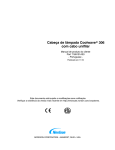
Targis® System
CoolWave® Control Unit
User Manual
1 of 143
Part Number 250023-001 Rev G
Table Of Contents
Patient Safety Summary
1: System Description
2: Treatment Session Setup
3: Treatment Instructions
4: Equipment Maintenance
5: Appendix - Troubleshooting Guide
Glossary Treatment Timer Algorithm
2 of 143
Part Number 250023-001 Rev G
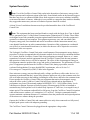
Patient Safety Summary
This patient safety summary is an overview of the key patient safety information provided in the
CoolWave® Control Unit User Manual. Please refer to the user manual to obtain all safety
information pertaining to the use and operation of the CoolWave Control Unit.
•
•
•
The treating physician should be present at all times during treatment.
Perform an enema 1 to 2 hours before treatment or per physician instructions. An enema is
mandatory.
It is critical that, throughout the patient’s treatment, the treating physician verify the correct
position of the microwave catheter and the rectal unit. Patient safety is at risk if the following
simple and straightforward safety check procedures are not correctly observed.
Safety Checks
1. Throughout the duration of the treatment, verify that the position mark on the
catheter remains at a fixed distance from the penile meatus.
2. It is strongly recommended that at least every 5 - 10 minutes of the treatment,
the correct position of the location balloon and the rectal unit is checked.
3. Always immediately check microwave catheter and rectal unit placement if
the patient complains of any abnormal or sudden increase in pain. Pause the
treatment if the patient complains of serious pain.
4. Observe the treatment parameters for sudden changes in readings, especially
decreases in temperatures that might indicate a sensor has moved from its
previous position.
Warnings
•
•
•
The Cooled ThermoTherapy™ Procedure must not be initiated without
assurance that the microwave catheter is properly positioned in the patient.
The correct positioning of the catheter must always be checked by
ultrasound imaging prior to commencing treatment. Improper placement
or orientation of the microwave catheter may lead to procedure failures or
heating damage of nontarget tissues such as the bladder neck, external
sphincter, or penile urethra.
Do not underinflate or overinflate the microwave catheter balloon.
Underinflation can cause the microwave antenna to be misplaced in the
prostate, affecting the external sphincter or penile urethra. Overinflation may
result in balloon malfunction and possible improper positioning of the
microwave antenna.
The rectal unit must be positioned and inflated properly to ensure correct
temperature sensing.
Part Number 250023-001 Rev G
3 of 143
Table of Contents
Patient Safety Summary ............................................................................................... 3 1 Systems Description ........................................................................................... 9 1.1 1.2 1.3 1.4 1.5 1.6 1.7 1.8 1.9 Notice ...................................................................................................................................... 9 Safety symbols and definitions ............................................................................................... 9 User Manual Overview ......................................................................................................... 10 Precautions ............................................................................................................................ 10 Introduction to the CoolWave® Control Unit ...................................................................... 12 Targis® System: CoolWave® Control Unit equipment overview ....................................... 12 Required equipment .............................................................................................................. 20 CoolWave® Control Unit Installation and Use Environment .............................................. 21 Safety instructions................................................................................................................. 24 2 Treatment Session Setup .................................................................................. 27 2.1 2.2 2.3 2.4 2.5 2.6 2.7 2.8 2.9 General safety precautions .................................................................................................... 27 Treatment session setup overview ........................................................................................ 27 Preparing the Patient for Treatment ...................................................................................... 27 Positioning and preparing the CoolWave® Control Unit ..................................................... 28 Installing the Coolant Bag .................................................................................................... 29 Inserting the microwave catheter .......................................................................................... 32 Inserting the Single-Use Standard RTU ............................................................................... 35 Inserting the RTU Plus Reusable Handle and Single-Use Balloon ...................................... 36 Connecting the Microwave Catheter and Rectal Unit to the CoolWave® Control Unit ...... 39 3 Treatment Instructions...................................................................................... 43 3.1 3.2 3.3 3.4 3.5 3.6 3.7 System Navigation and Screen Overview ............................................................................ 43 CoolWave® Control Unit setup............................................................................................ 49 Cooled ThermoTherapy™ Procedure ................................................................................... 53 Post-treatment ....................................................................................................................... 79 Control Unit options ............................................................................................................. 80 System errors ........................................................................................................................ 88 Treatment modes................................................................................................................... 91 4 Equipment Maintenance ................................................................................... 95 4.1 4.2 4.3 4.4 4.5 4.6 4.7 Cleaning the equipment ........................................................................................................ 95 Maintaining the CoolWave® Control Unit .......................................................................... 96 Maintaining the printer ......................................................................................................... 98 Moving the CoolWave® Control Unit ............................................................................... 101 Storing the CoolWave® Control Unit ................................................................................ 102 Shipping the CoolWave® Control Unit .............................................................................. 102 CoolWave® Control Unit specifications ............................................................................ 103 5 Appendix ........................................................................................................ 105 5.1 5.2 5.3 5.4 5.5 Troubleshooting guide ........................................................................................................ 105 Treatment screen flowchart ................................................................................................ 118 Description of symbols ....................................................................................................... 119 Patient Comfort Kit ............................................................................................................. 122 Glossary .............................................................................................................................. 123 4 of 143
Part Number 250023-001 Rev G
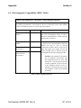
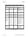
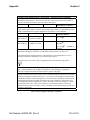
5.6 5.7 Electromagnetic Compatibility (EMC) Tables ................................................................... 131 Index ................................................................................................................................... 135 List of Figures:
Figure 1-1. CoolWave Control Unit................................................................................................................ 12 Figure 1-2. Patient Connection Cable Housing............................................................................................... 13 Figure 1-3. Touchscreen monitor .................................................................................................................... 14 Figure 1-4. Keyboard ...................................................................................................................................... 14 Figure 1-5. Printer ........................................................................................................................................... 15 Figure 1-6. ON/OFF power switch ................................................................................................................. 15 Figure 1-7. Wheel lock tabs ............................................................................................................................ 16 Figure 1-8. Coolant system features................................................................................................................ 16 Figure 1-9. Power indicators ........................................................................................................................... 17 Figure 1-10. Microwave Off pushbutton ........................................................................................................ 17 Figure 1-11. Volume Control, Headphone jack, USB Ports ........................................................................... 18 Figure 1-12. Microwave catheter .................................................................................................................... 18 Figure 1-13. Single-use standard RTU............................................................................................................ 19 Figure 1-14. Assembled RTU Plus (with the reusable handle and single use balloon) .................................. 19 Figure 1-15. Coolant Bag ................................................................................................................................ 20 Figure 1-16. CoolWave Control Unit Rear ..................................................................................................... 22 Figure 2-1. Filling the coolant bag .................................................................................................................. 29 Figure 2-2. Positioning the Coolant Bag onto the Top Mounting Pins ........................................................... 30 Figure 2-3. Positioning the Coolant Bag onto the Lower Mounting Pin ........................................................ 30 Figure 2-4. Coolant System with Pump Mechanism Open ............................................................................. 31 Figure 2-5. Positioning the Sensor Module..................................................................................................... 31 Figure 2-6. Coolant System with Pump Closed .............................................................................................. 32 Figure 2-7. CTC Advance® Microwave Catheter .......................................................................................... 34 Figure 2-8. Inserted Microwave Catheter and Standard RTU ........................................................................ 35 Figure 2-9. Standard RTU ............................................................................................................................... 35 Figure 2-10. RTU Plus Reusable Handle ........................................................................................................ 36 Figure 2-11. RTU Plus Disposable Balloon .................................................................................................... 37 Figure 2-12. Inserting the Temperature Sensor Strip ...................................................................................... 37 Figure 2-13. Proper Positioning of the Temperature Sensor Strip .................................................................. 38 Figure 2-14. Assembled RTU Plus with Deployed Sheath ............................................................................. 38 Figure 2-15. Connected Microwave Catheter and Rectal Unit ....................................................................... 40 Figure 2-16. Isolate the Antenna Cable and Catheter Handle Using the Microwave Catheter Holder ........... 41 Figure 2-17. Patient Connection Cable Housing............................................................................................. 41 Figure 3-1. Pressed and Nonpressed Buttons .................................................................................................. 43 Figure 3-2. Data Field ..................................................................................................................................... 43 Figure 3-3. Example of a CoolWave Control Unit Dialog Box ...................................................................... 44 Figure 3-4. Screen Overview .......................................................................................................................... 45 Figure 3-5. Example of a Treatment Screen in Demonstration Mode ............................................................ 46 Figure 3-6. Help Window ............................................................................................................................... 47 Figure 3-7. Notes Dialog Box ......................................................................................................................... 48 Figure 3-8. Notes Entry Window .................................................................................................................... 49 Figure 3-9. Login Screen ................................................................................................................................ 50 Figure 3-10. User Login Window ................................................................................................................... 51 Figure 3-11. Create New User Window .......................................................................................................... 51 Part Number 250023-001 Rev G
5 of 143
Figure 3-12. User Login Window ................................................................................................................... 52 Figure 3-13. Main Menu Screen ..................................................................................................................... 53 Figure 3-14. Patient Information Screen ......................................................................................................... 55 Figure 3-15. Example of a Protocol Screen .................................................................................................... 56 Figure 3-16. Readjust connectors, tags, and serial number labels .................................................................. 57 Figure 3-17. Example of Protocol screen - modify ......................................................................................... 59 Figure 3-18. Example of treatment protocol - modify .................................................................................... 59 Figure 3-19. Treatment Checklist screen and Microwave Off pushbutton ..................................................... 61 Figure 3-20. Treatment Checklist screen - Demonstration mode ................................................................... 62 Figure 3-21. System Calibration screen .......................................................................................................... 62 Figure 3-22. System Calibration Screen - Error Message ............................................................................... 63 Figure 3-23. Urologix - BPH Treatment screen .............................................................................................. 64 Figure 3-24. Microwave Off Pushbutton ........................................................................................................ 65 Figure 3-25. Chart pane .................................................................................................................................. 66 Figure 3-26. Event pane .................................................................................................................................. 67 Figure 3-27. Detail pane.................................................................................................................................. 68 Figure 3-28. Treatment diagram ..................................................................................................................... 68 Figure 3-29. Print window .............................................................................................................................. 69 Figure 3-30. Treatment Cooldown window .................................................................................................... 70 Figure 3-31. Standard mode ............................................................................................................................ 71 Figure 3-32. Example of a treatment parameter control panel ........................................................................ 72 Figure 3-33. Advanced mode .......................................................................................................................... 72 Figure 3-34. Example of a treatment parameter control panel ........................................................................ 74 Figure 3-35. Manual mode .............................................................................................................................. 75 Figure 3-36. Example of a treatment parameter control panel ........................................................................ 76 Figure 3-37. Resume Treatment dialog box .................................................................................................... 76 Figure 3-38. Treatment Cooldown window .................................................................................................... 77 Figure 3-39. Treatment Cooldown - End window .......................................................................................... 77 Figure 3-40. Treatment Cooldown - End window .......................................................................................... 78 Figure 3-41. Options Menu screen .................................................................................................................. 80 Figure 3-42. User Settings screen ................................................................................................................... 81 Figure 3-43. Printer Utilities screen ................................................................................................................ 82 Figure 3-44. Data View/Print/Copy screen ..................................................................................................... 83 Figure 3-45. Password Setup window............................................................................................................. 84 Figure 3-46. Example of a System Settings screen ......................................................................................... 85 Figure 3-47. System Settings screen―date .................................................................................................... 86 Figure 3-48. System Settings screen―time .................................................................................................... 86 Figure 3-49. System Settings screen―language ............................................................................................. 87 Figure 3-50. System Settings screen―volume ............................................................................................... 87 Figure 3-51. Example of a System Settings screen―apply ............................................................................ 88 Figure 3-52. Example of a System Error screen - error message .................................................................... 89 Figure 3-53. Example of a System Calibration screen - error message .......................................................... 90 Figure 4-1. Internal coolant level indicator ..................................................................................................... 97 Figure 4-2. Control Unit rear cover................................................................................................................. 98 Figure 4-3. Printer overview ........................................................................................................................... 99 Figure 4-4. Insert the new ink tank ............................................................................................................... 100 Figure 5-1. Treatment screen flowchart ........................................................................................................ 118 Figure 5-2. Microwave catheter Holder ........................................................................................................ 122 Figure 5-3. Knee cushions ............................................................................................................................ 122 6 of 143
Part Number 250023-001 Rev G
List of Tables:
Table 1-1. Safety Symbols and Definitions ...................................................................................................... 9 Table 1-2. Urologix provided equipment ........................................................................................................ 20 Table 1-3. Clinic provided equipment ............................................................................................................ 21 Table 1-4. CoolWave Control Unit Power Cords ........................................................................................... 23 Table 2-1. Microwave Catheter Identification ................................................................................................ 33 Table 3-1. Safety Checks During Treatment................................................................................................... 55 Table 3-2. Microwave catheter identification ................................................................................................. 58 Table 3-3 Treatment Timer algorithms ........................................................................................................... 60 Table 3-4. Treatment Timer algorithms .......................................................................................................... 65 Table 3-5 Treatment Timer algorithms ........................................................................................................... 71 Table 4-1. Fuse overview ................................................................................................................................ 98 Table 4-2. CoolWave Control Unit specifications ........................................................................................ 103 Table 5-2 Electromagnetic Emissions........................................................................................................... 131 Table 5-3 Electromagnetic Immunity ........................................................................................................... 132 Table 5-4 Electromagnetic Immunity (continued) ........................................................................................ 133 Table 5-5 Recommended Separation Distances ............................................................................................ 134 Part Number 250023-001 Rev G
7 of 143
8 of 143
Part Number 250023-001 Rev G
Section 1
System Description
1 Systems Description
1.1 Notice
The information contained in this manual is subject to change. This manual does not necessarily
address all safety concerns associated with the Urologix® CoolWave® Control Unit.
The CoolWave Control Unit is intended for use only by qualified medical personnel. Federal
(USA) law restricts this device to sale by or on the order of a physician trained and/or experienced
in the use of this device as outlined in the required training program.
Medical equipment, however sophisticated, should never be a substitute for the human care,
attention, and critical judgment that only trained healthcare professionals can provide.
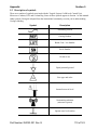
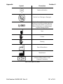
1.2 Safety symbols and definitions
The following safety symbols are used throughout this manual. Familiarize yourself with each
symbol and its meaning before using this equipment. You can find additional symbols associated
with the CoolWave Control Unit in Section 5.3, Description of symbols.
Safety Symbol
Definition
A note indicates important information that
helps you operate the CoolWave Control Unit or
use the disposable devices.
Note
Caution
Warning
Instruction Manual
A caution contains instructions that must be
followed to avoid a possible malfunction of or
damage to the equipment or its connected
devices. Do not proceed beyond a caution sign
until the indicated conditions are fully
understood and met.
A warning contains important information about
possible danger to you or the patient. Do not
proceed beyond a warning sign until the
indicated conditions are fully understood and
met.
The instruction manual symbol is displayed on
the product when it is necessary for you to refer
to the CoolWave Control Unit User Manual (this
document).
Table 1-1. Safety Symbols and Definitions
9 of 143
Part Number 250023-001 Rev G
Section 1
System Description
1.3 User Manual Overview
This manual combines technical reference material as well as information on how to use the
CoolWave Control Unit.
Notes:
• For information regarding the contents of this manual, please call Urologix Customer
Service at 1-888-229-0772.
• Read this manual before operating the CoolWave Control Unit.
Section 1: System Description provides an overview of the CoolWave Control Unit equipment.
This section also provides important notes about using the CoolWave Control Unit including
information on installation, use environment, equipment connections, equipment testing, and safety
instructions.
Section 2: Treatment Session Setup describes how to prepare the patient, prepare the CoolWave
Control Unit, install the coolant bag, and insert the microwave catheter and the RTU (rectal unit).
Section 3: Treatment Instructions provides instruction on how to use the CoolWave Control Unit
from logging into the CoolWave Control Unit to beginning and ending a Cooled ThermoTherapy™
procedure. You will also find information on how to change system settings, handle system errors,
and work in demonstration mode.
Section 4: Equipment Maintenance presents information on post-treatment cleaning procedures
and storage instructions. You will also find information on how to move and ship the CoolWave
Control Unit. Finally, this section discusses how to maintain the equipment, though some
maintenance requires a Urologix trained service representative.
Section 5: Appendix includes a troubleshooting guide, a flowchart of the treatment screens, a
description of the symbols used in the manual and on the labels, an overview of the Patient
Comfort Kit, and a glossary of terms used in CoolWave Control Unit literature.
1.4 Precautions
Only those physicians who have been thoroughly trained on the operation of the CoolWave Control
Unit and the Cooled ThermoTherapy Procedure should deliver the treatment.
The Cooled ThermoTherapy Procedure must not be initiated without assurance that the microwave
catheter is properly positioned in the patient. The correct positioning of the microwave catheter
must always be checked by ultrasound imaging prior to commencing treatment. Improper
placement or orientation of the microwave catheter may lead to procedure failures or heating
damage of non-target tissues such as the bladder neck, external sphincter, or penile urethra.
All components of the CoolWave Control Unit must be used in a manner consistent with the
instructions set forth in their respective instructions for use insert and the CoolWave Control Unit
User Manual (this document). Failure to do so may result in insufficient treatment or increased risk
of injury or infection to the patient.
10 of 143
Part Number 250023-001 Rev G
System Description
Section 1
Note: Use of the CoolWave Control Unit results in the deposition of microwave energy in the
patient’s prostate and in adjacent regions of the body. Some animal studies in the literature suggest
that there may be as yet unknown health effects from exposure to microwave radiation, including
an increased incidence of tumors. Although it is not possible to extrapolate these studies to humans,
they suggest that unnecessary microwave radiation exposure should be avoided.
At least 20 cm of ventilation clearance must be provided around the base of the CoolWave®
Control Unit.
Note: This equipment has been tested and found to comply with the limits for a Class A digital
device, pursuant to part 15 of the Federal Communication Commission (FCC) Rules. These limits
are designed to provide reasonable protection against harmful interference when the equipment is
operated in a commercial environment. This equipment generates, uses, and can radiate radio
frequency energy and, if not installed and used in accordance with the instruction manual, may
cause harmful interference to radio communications. Operation of this equipment in a residential
area is likely to cause harmful interference, in which case the user will be required to correct the
interference at his own expense.
The Urologix® CoolWave Control Unit emits a small amount of electromagnetic energy during a
procedure. Urologix recommends that all electronic medical devices be kept at a minimum distance
of 1.0 meter from the CoolWave Control Unit when performing a treatment. However, a 1-meter
separation of electronic medical equipment from the CoolWave Control Unit does not guarantee
that operation of other devices will not be impacted. The effect of this electromagnetic energy on
all equipment cannot be predicted due to age and quality of maintenance. The performance of each
piece of equipment operated near the CoolWave Control Unit, during a procedure, must be
evaluated for degradation. For more detailed EMC requirements, refer to Section 5.6
Electromagnetic Compatibility (EMC) Tables in the Appendix.
Since microwave energy can travel through walls, ceilings, and floors to affect other devices, it is
important to understand that the 1-meter safety distance applies not only to the treatment room, but
also to all adjacent rooms in the building, including the rooms above and below the treatment room.
Do not operate the CoolWave Control Unit near equipment that emits electromagnetic energy,
unless the effect on the CoolWave Control Unit has been evaluated and no degradation of
performance was found. The national standard ANSI/IEEE C95.1 - 1999 Edition (Safety Levels
with Respect to Human Exposure to Radio Frequency Electromagnetic Fields) recommends a
maximum stray field exposure level for whole body exposure of 3 mW/cm2, as averaged for any 6
minute period. The maximum radiated field, at full power, from the CoolWave Control Unit patient
cable and microwave catheter, at 5 centimeters, is 2.1 mW/cm2. Urologix recommends that the
operator maintain a minimum distance of 5 centimeters from the patient cable and exposed portions
of the microwave catheter during the procedure.
Operate the CoolWave Control Unit and connected devices only when connected to a fully tested,
hospital grade power outlet with adequate grounding.
The CoolWave Control Unit must be plugged into the appropriate voltage outlet.
Part Number 250023-001 Rev G
11 of 143
Section 1
System Description
The electrical equipment inside the CoolWave Control Unit uses voltages capable of causing
serious injury or death from electric shock. To avoid this hazard, never open the housing of the
CoolWave Control Unit.
1.5 Introduction to the CoolWave® Control Unit
The CoolWave Control Unit treats Benign Prostatic Hyperplasia (BPH) by applying microwave
power to the prostate. This microwave power, when applied to the prostate, heats the diseased
tissue via a microwave catheter. This microwave catheter also minimizes patient discomfort and
risk to the urethra by circulating cooling fluid. In addition, rectal wall damage is prevented by
continuously monitoring rectal wall temperature readings throughout the treatment. If during a
treatment, urethra or rectal temperatures exceed protocol (treatment) parameters, the system will
adjust microwave power to protect the urethra or rectal wall from overheating.
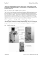
1.6 Targis® System: CoolWave® Control Unit equipment overview
The Targis System is comprised of a CoolWave control unit model 5000 series, a Procedure Kit
(comprised of a microwave catheter, a rectal unit, and a coolant bag), and accessories. For this user
manual, the representative microwave catheter is the CTC Advance® Microwave Catheter.
1.6.1
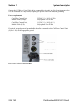
CoolWave Control Unit
Figure 1-1. CoolWave Control Unit
12 of 143
Part Number 250023-001 Rev G
System Description
Section 1
The CoolWave® Control Unit (Figure 1-1) supplies microwave energy and coolant to the
microwave catheter and collects temperature data from the microwave catheter and the rectal unit.
The CoolWave Control Unit also provides a way of entering patient data, controlling treatment
parameters (e.g., ramp rate, coolant temperature, and treatment time), and monitoring rectal and
urethra temperatures. The CoolWave Control Unit includes these features:
• Patient connection cable and patient connection cable housing
• Touchscreen monitor
• Keyboard
• Printer
• ON/OFF power switch
• Lockable wheels
• Coolant system
• Main power indicator and microwave power indicator
• Microwave Off pushbutton
• Other: Volume control, headphone jack, USB ports
Note: The service port is reserved for use by Urologix® service personnel only.
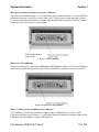
Patient Connection Cable and Patient Connection Cable Housing
Data from the microwave catheter and the rectal unit enters the CoolWave Control Unit via the
patient connection cable and patient connection cable housing (Figure 1-2).
Figure 1-2. Patient Connection Cable Housing
The patient connection cable housing contains connectors for the rectal unit, fiber optic connector,
and microwave antenna connector. When not in use, place the patient connection cable and housing
in the cable holder located on the back of the CoolWave Control Unit.
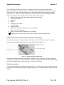
Touchscreen monitor
View a treatment using the touchscreen monitor (Figure 1-3) and, when necessary, adjust treatment
parameters. The monitor can be tilted for improved viewing. To open the monitor, operate the latch
and lift.
Part Number 250023-001 Rev G
13 of 143
Section 1
System Description
Figure 1-3. Touchscreen monitor
Keyboard
Enter patient data using the keyboard (Figure 1-4). The keys are sealed to prevent damage from
spillage onto the keyboard. To access the keyboard, lift the touchscreen monitor into an upright
position.
Figure 1-4. Keyboard
14 of 143
Part Number 250023-001 Rev G
System Description
Section 1
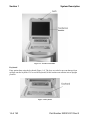
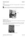
Printer
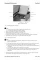
Print data from any treatment using the Canon® color inkjet printer (Figure 1-5). The printer drawer
pulls out and holds the printer.
Caution: The CoolWave Control Unit can tip over if you press down on the open printer
drawer with too much weight. Do not press down on the open drawer with more than 20 kg (44
lbs).
Figure 1-5. Printer
ON/OFF power switch
Instruction Manual: Read the CoolWave Control Unit User Manual (this document) before
turning ON and operating the system.
Turn the CoolWave Control Unit ON or OFF with this power switch (Figure 1-6) located on the
back of the CoolWave Control Unit. When not in use, place the power cord in the cable holder
located on the back of the CoolWave Control Unit.
Figure 1-6. ON/OFF power switch
Part Number 250023-001 Rev G
15 of 143
Section 1
System Description
Lockable wheels
Keep the CoolWave® Control Unit from moving by locking the front wheels (Figure 1-7).
Figure 1-7. Wheel lock tabs
To lock the wheels, use your foot to press down on the wheel lock tabs. To unlock the wheels,
press on the back part of the wheel lock tabs.
Coolant System
The coolant system consists of a chill plate, temperature and pressure sensors, a peristaltic pump
mechanism, and a coolant bag (Figure 1-8).
Figure 1-8. Coolant system features
Chill plate: The chill plate, located behind the coolant door (Figure 1-8), is equipped with
mounting pins to hold the coolant bag securely against the chill plate surface.
Temperature and pressure sensors: These sensors, located on the CoolWave Control Unit,
monitor the coolant temperature and the coolant pressure (Figure 1-8).
Peristaltic pump mechanism: The peristaltic pump mechanism (Figure 1-8) circulates the coolant.
Coolant bag: The coolant bag (Figure 1-8) serves as the reservoir for the coolant.
16 of 143
Part Number 250023-001 Rev G
System Description
Section 1
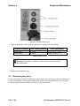
Main power indicator and microwave power indicator
The main power indicator (Figure 1-9), located under the touchscreen monitor, is a green LED that
illuminates when the CoolWave® Control Unit is ON. The microwave power indicator (Figure 19), also located under the monitor, is an amber LED that illuminates when the CoolWave Control
Unit delivers microwave power to the prostate.
Figure 1-9. Power indicators
Microwave Off pushbutton
If there is an emergency, press the red Microwave Off pushbutton (Figure 1-10), located under the
touchscreen monitor and right of the green LED, to immediately turn the microwave power OFF.
Figure 1-10. Microwave Off pushbutton
Other: Volume control, headphone jack, USB ports
The CoolWave® Control Unit includes a volume control, a headphone jack, and two USB
(Universal Serial Bus) ports (Figure 1-11), all located under the touchscreen monitor. Either of the
USB ports can accommodate a single USB flash drive.
Part Number 250023-001 Rev G
17 of 143
Section 1
System Description
Figure 1-11. Volume Control, Headphone jack, USB Ports
1.6.2
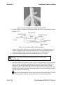
Microwave Catheter
The single-use microwave catheter includes a fiber optic temperature sensor to measure urethra
temperature, a microwave antenna and cable, cooling channels and connectors, a urine drainage
port that connects to a standard urine drainage bag, and a location balloon to position the catheter at
the bladder neck (Figure 1-12). The microwave antenna and temperature sensor are connected to
the CoolWave Control Unit via the patient connection cable housing and patient connection cable.
To ensure that the microwave catheter is positioned properly within the urethra, the location
balloon is inflated to hold the catheter in place during treatment.
Figure 1-12. Microwave catheter
The microwave catheter is used for:
• Delivering microwave energy to the targeted prostatic tissue.
• Monitoring the urethra temperature.
• Cooling the urethra during treatment.
• Draining urine during treatment.
18 of 143
Part Number 250023-001 Rev G
System Description
1.6.3
Section 1
Rectal Thermosensing Unit (RTU)
The CoolWave Control Unit requires the use of either the single-use standard RTU or the RTU
Plus with reusable handle and single-use balloon. The standard RTU and RTU Plus (Figure 1-13
and Figure 1-14) both consist of an inflatable balloon with 5 temperature sensors. These sensors
monitor rectal temperature along the anterior rectal wall and send this information to the CoolWave
Control Unit during a treatment. After inserting one of the rectal units into the rectum, inflating the
rectal balloon with air holds the thermosensors in place against the anterior rectal wall nearest the
prostate.
Figure 1-13. Single-use standard RTU
Figure 1-14. Assembled RTU Plus (with the reusable handle and single use balloon)
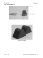
1.6.4
Coolant Bag
The single-use coolant bag includes a coolant bag, inlet and outlet tubing, connectors, and a sensor
module (Figure 1-15). The sensor module allows the CoolWave® Control Unit to monitor coolant
temperature and pressure in order to maintain coolant temperatures within acceptable limits and to
ensure that the coolant circulates properly. The coolant bag also includes 2 small holes on the top
and 1 hole on the bottom for mounting the bag on the chill plate and a hydrophobic vent to release
air (but not coolant) from inside the bag.
Part Number 250023-001 Rev G
19 of 143
Section 1
System Description
Figure 1-15. Coolant Bag
The function of the coolant bag is to provide a reservoir for the coolant that circulates through the
microwave catheter during a treatment. The coolant circulates through the coolant bag via the
peristaltic pump mechanism. The coolant inlet tubing runs across the pump mechanism, which
pushes the coolant through the inlet tubing, the sensor module, the coolant bag, and the outlet
tubing. Coolant continuously circulates through the microwave catheter, connected to the coolant
outlet tubing, and returns to the coolant bag via the coolant inlet tubing. The coolant bag resides
against the chill plate, which chills the circulating coolant.
1.7 Required equipment
The following equipment, including an ultrasound system, is needed to successfully treat patients
with the CoolWave Control Unit.
1.7.1
Equipment provided by Urologix
Urologix provides the following equipment.
Quantity
1
1
1
1
1
Equipment/Material
CoolWave® Control Unit
CoolWave Control Unit User Manual (this document)
Kit containing either Targis®, Cooled ThermoCath®, or CTC
Advance® Microwave Catheter
• 1 microwave catheter
• 1 Rectal thermal unit standard RTU or RTU Plus
• 1 coolant bag
Patient Comfort Kit (2 knee cushions and a Microwave Catheter
Holder)
Transport Kit, optional (trolley and electrical safety tester)
Table 1-2. Urologix provided equipment
1.7.2
Equipment Provided by the Clinic
The clinic typically provides the following equipment.
20 of 143
Part Number 250023-001 Rev G
System Description
Section 1
Quantity
1
1
1
As needed
As needed
50 cc
As needed
1
1
2
200 cc
1
1
As needed
As needed
1
1
1
As needed
Equipment/Material
Foley catheter, 16-18 French
Straight catheter, 14-16 French
Urine drainage bag
Sterile gloves
Anesthetic lubricating jelly (Urojet or lidocaine jelly)
Local bladder anesthetic of choice (e.g., 50 cc of 1% or 2%
lidocaine without epinephrine)
Water soluble lubricating gel (e.g., K-Y® Jelly)
60 cc luer-lock syringe
60 cc catheter-tip syringe (i.e., Toomey™ syringe)
10 cc luer-lock syringe
Sterile water for coolant bag and catheter balloons
Ultrasound system
Catheter plug
Permanent marker or tape
Nonsterile gloves
Penile clamp
Specimen cup
Urinal or graduate
Ice or ice pack
Table 1-3. Clinic provided equipment
1.8 CoolWave® Control Unit Installation and Use Environment
1.8.1
Installation
Warning: DO NOT USE components that have evidence of a compromised package or
damage.
Before unpacking the CoolWave Control Unit, inspect the shipping crate for signs of damage.
Remove the CoolWave Control Unit from the shipping crate, and retain the shipping crate to return
the CoolWave Control Unit for service, if needed. Then, prior to using the CoolWave Control Unit,
visually inspect the following components for damage:
• CoolWave Control Unit for obvious damage
• Pump latch and coolant door to see that they are operating correctly
• Patient connection cable, patient connection cable housing, and connectors for kinks, cuts,
dirt, contamination, or obvious damage
• Microwave catheter for kinks, cuts, or obvious damage
• Rectal unit for kinks, cuts, or obvious damage
• Coolant Bag for kinks, cuts, or obvious damage
Part Number 250023-001 Rev G
21 of 143
Section 1
System Description
Operate the CoolWave Control Unit and its connected devices only in clinical environments where
it can be connected to a fully tested, hospital-grade power outlet with adequate grounding.
Power requirements
CoolWave Control Unit,
Model 5000E (Europe):
220/240 V [+/- 10%] (4.25 A)
Single phase 50 or 60 Hz
CoolWave Control Unit,
Model 5000A (US):
110/120 V [+/- 10%] (8.5 A)
Single phase 50 or 60 Hz
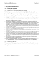
If required, an equal potential ground cable should be connected to the CoolWave Control Unit
(Figure 1-16) and the appropriate ground.
Figure 1-16. CoolWave Control Unit Rear
22 of 143
Part Number 250023-001 Rev G
System Description
Section 1
CoolWave® Control Unit Power Cords
Urologix provides the following power cords for use with the CoolWave Control Unit.
End View
Power Cord Catalog Number
Catalog Number: AC1011
France
Austria
Germany
Norway
Belgium
Sweden
Netherlands
Finland
Catalog Number: AC1012
Australia
New Zealand
Catalog Number: AC1013
United Kingdom
Ireland
Catalog Number: AC1014
Denmark
Catalog Number: AC1015
Italy
Catalog Number: AC1017
Canada
United States
Mexico
Catalog Number: AC1018
Switzerland
Table 1-4. CoolWave Control Unit Power Cords
Equipment connections
The CoolWave Control Unit must not be connected to any device other than the microwave
catheter, rectal unit, or coolant bag. In addition, the microwave catheter, rectal unit, and coolant bag
must not be connected to any other device or outlet.
Equipment testing
Turn the CoolWave® Control Unit ON, and verify that the Login screen display appears. Do not
use the CoolWave Control Unit if there are any irregular sounds or vibrations present.
Part Number 250023-001 Rev G
23 of 143
Section 1
System Description
Prior to beginning a Cooled ThermoTherapy™ procedure, verify that all components of the
Procedure Kit (microwave catheter, RTU, and coolant bag) have arrived in a sealed condition.
1.8.2
•
Use Environment
Cautions:
Do not stack any objects on top of CoolWave Control Unit, microwave catheter, RTU, or
coolant bag.
•
Do not place the CoolWave Control Unit near any electronic device or other equipment
emitting electromagnetic waves. The interference may compromise the operation of the
equipment.
•
Provide ventilation space of at least 20-cm clearance around the base of the CoolWave Control
Unit for operation.
•
Do not turn ON the CoolWave Control Unit with the touchscreen monitor lid closed. The
touchscreen will turn OFF, and the lid may become warm to the touch.
•
Operate the CoolWave Control Unit on a level surface.
•
Operate the CoolWave Control Unit under these operating conditions:
An ambient temperature range of +10°C to +30°C,
A relative humidity range of 30% to 75%,
An atmospheric pressure range of 700 hPa to 1,060 hPa
1.9 Safety instructions
Warning: Do not open the housing of the CoolWave Control Unit. Doing so risks receiving an
electric shock. Refer all CoolWave Control Unit servicing to qualified Urologix® personnel.
Warning: This equipment is not intended for use in areas where there is a danger of explosion.
Do not use the CoolWave Control Unit in the presence of flammable substances.
Caution: The CoolWave Control Unit must be operated by trained and authorized personnel.
You should read and understand the instructions in this manual before operating the system.
This manual does not claim to address all of the safety concerns associated with the use of this
equipment. You must establish appropriate safety and health practices prior to use.
24 of 143
Part Number 250023-001 Rev G
System Description
Section 1
Perform the following CoolWave Control Unit safety checks at least once every 12 months:
• Cables and connectors for damage
• Equipment for physical damage
• Safety labels are readable
Maintain a written record of these safety checks, and service any equipment that does not meet
these standards.
Part Number 250023-001 Rev G
25 of 143
Section 1
System Description
26 of 143
Part Number 250023-001 Rev G
Treatment Session Setup
Section 2
2 Treatment Session Setup
2.1 General safety precautions
The CoolWave® Control Unit is a medical device equipped with the ability to emit microwave
radiation. Therefore, observe the following general safety precautions:
•
•
•
•
The CoolWave Control Unit must only be installed and serviced by
qualified service personnel.
The CoolWave Control Unit may not be used for any purpose other than
those for which it is designed and approved, and then only in accordance
with this manual.
The CoolWave Control Unit may be used only by authorized and
properly trained personnel and the treating physician must be present
throughout the duration of the Cooled ThermoTherapy™ procedure. The
CoolWave Control Unit display must be monitored and controlled during
the course of a treatment session to make sure that the urethral and rectal
temperatures are within prescribed treatment parameters.
The CoolWave Control Unit must never be left unattended when the
machine is switched ON.
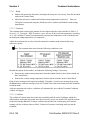
The CoolWave Control Unit is exclusively for
use by physicians who have been trained.
The treating physician should be present at all
times during treatment.
2.2 Treatment session setup overview
The treatment session requires several preparation steps. Some of these steps may be done
concurrently.
1. Preparing the patient for treatment.
2. Positioning and preparing the CoolWave Control Unit.
3. Installing the coolant bag.
4. Inserting the microwave catheter.
5. Inserting the single-use standard RTU, or inserting the RTU Plus with reusable handle
and single-use balloon.
6. Connecting the microwave catheter and RTU to the CoolWave Control Unit.
2.3 Preparing the Patient for Treatment
1. Ensure the patient has received adequate information about the treatment and posttreatment expectations and has provided informed consent.
Part Number 250023-001 Rev G
27 of 143
Section 2
Treatment Session Setup
2. Perform an enema 1 to 2 hours before treatment or per physician instructions.
An enema is mandatory.
3. Administer pre-procedure medications such as local anesthetics, antibiotics, nonsteroidal anti-inflammatory agents, analgesics, or anti-anxiety medications (generally
given 1 hour prior to the start of microwave power delivery). It is important that the
patient not be over sedated. This may compromise his ability to communicate pain.
Note: Medications, such as anti-inflammatory agents, may be given to the patient at
the discretion of the physician based on the patient’s physical and mental well-being.
2.4 Positioning and preparing the CoolWave® Control Unit
1. Position the CoolWave Control Unit on a level surface and close enough to the patient
so that the patient connection cable connects easily to the microwave catheter and the
RTU.
2. Lock the front wheels of the CoolWave Control Unit to prevent it from accidentally
moving. To lock the wheels, use your foot to press down on the wheel lock tabs. To
unlock the wheels, press on the back part of the wheel lock tabs.
3. Plug the CoolWave Control Unit electrical cord to a wall outlet. The connection
requires a fully tested, hospital-grade power outlet with adequate grounding, and the
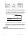
power supply must meet the following specifications:
Power requirements
Control Unit, Model 5000E
(Europe):
Control Unit, Model 5000A (US):
220/240 V [+/- 10%] (4.25 A)
Single phase 50 or 60 Hz
110/120 V [+/- 10%] (8.5 A)
Single phase 50 or 60 Hz
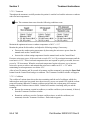
Warning: Do not move the CoolWave Control Unit while the
electrical cord is connected to a power source.
4. Turn ON the CoolWave Control Unit and login to the system. Refer to Section 3.2,
CoolWave® Control Unit setup, for further information.
Note: Turn ON the CoolWave Control Unit at least 5 minutes before treatment begins to allow
the system to warm up.
5. Enter patient and clinical information on the Patient Information screen. Refer to
Section 3.3.1, Patient Information screen, for further information.
Note: For first-time users, it may be helpful to read Section 3.1, System Navigation and Screen
Overview, prior to entering patient and clinical information on the Patient Information screen.
28 of 143
Part Number 250023-001 Rev G
Treatment Session Setup
Section 2
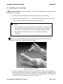
2.5 Installing the Coolant Bag
Instruction Manual: Read the CoolWave Control Unit User Manual (this document) before
installing the Coolant Bag.
1. Open the package containing the coolant bag, and remove the coolant bag.
2. Fill the coolant bag with 100 cc (± 5 cc) of sterile water by injecting the water into the
female luer fitting of the coolant bag with a syringe (Figure 2-1).
Cautions:
•
•
Use only sterile water in the coolant bag. Do not fill the coolant bag with
saline solution. Saline solution has electrical properties that can interfere
with microwave energy from the microwave catheter during treatment.
Do not allow the coolant bag connectors to fall on the floor during
installation.
Note: To prevent water from leaking out of the coolant bag once it has been filled,
temporarily connect the coolant bag connectors together.
Figure 2-1. Filling the coolant bag
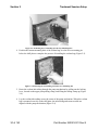
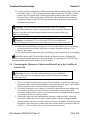
3. Open the coolant door on the right side of the CoolWave® Control Unit by pulling the
top of the door forward. Position the coolant bag over the chill plate by aligning the top
two mounting holes of the coolant bag with the top two mounting pins on the chill plate.
Gently position the coolant bag onto the pins (Figure 2-2).
Part Number 250023-001 Rev G
29 of 143
Section 2
Treatment Session Setup
Figure 2-2. Positioning the Coolant Bag onto the Top Mounting Pins
4. Position the bottom mounting hole of the coolant bag over the lower mounting pin
below the chill plate to complete the process of installing the coolant bag (Figure 2-3).
Figure 2-3. Positioning the Coolant Bag onto the Lower Mounting Pin
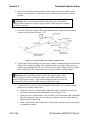
5. Route the coolant inlet tubing through the pump mechanism by pulling out the locking
lever, located on the upper pump tubing clamp, and lifting the tubing clamp up (Figure
2-4).
6. Lay the coolant inlet tubing across the center of the pump mechanism. When the coolant
bag is mounted correctly on the chill plate, the inlet tubing and sensor module are
aligned with the pump mechanism (Figure 2-4).
30 of 143
Part Number 250023-001 Rev G
Treatment Session Setup
Section 2
Figure 2-4. Coolant System with Pump Mechanism Open
7. Place the coolant inlet tubing under the upper pump tubing clamp and across the rotor of
the pump mechanism (Figure 2-4).
Note: Ensure that the coolant inlet tubing is not twisted.
8. Align the sensor module with the locating pins to the right of the pump mechanism
(Figure 2-5).
Figure 2-5. Positioning the Sensor Module
9. Ensure the coolant inlet tubing is properly seated in the notch of the lower pump
housing. Then, firmly push down on the upper pump tubing clamp until it snaps into
position (Figure 2-6).
Part Number 250023-001 Rev G
31 of 143
Section 2
Treatment Session Setup
Figure 2-6. Coolant System with Pump Closed
10. Insert the coolant inlet and outlet tubing into the tubing holder. This will prevent the
tubing from being pinched by the coolant door.
11. Close the coolant door completely.
Note: The coolant delivered to the microwave catheter may not be at the desired
temperature if the coolant door is not completely closed. In addition, a closed coolant door
prevents damage to the coolant bag.
2.6 Inserting the microwave catheter
1. Drain the patient’s bladder using only water-soluble lubricant in the process.
2. Instill an anesthetic mixture of choice into the bladder.
3. Insert a water-based anesthetic lubricant mixture of choice into the urethra, and clamp
the penis to contain the lubricant mixture within the urethra for 20-30 minutes.
Warning: Do not overinflate the microwave catheter balloon. Overinflation
may result in balloon malfunction and possible improper positioning of the
microwave antenna. Underinflation can cause the antenna to be misplaced in the
prostate, affecting the external sphincter.
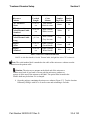
Warning: Selection and use of the appropriate catheter model is required to
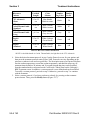
assure patient safety. Verify that the correct catheter has been inserted in the
patient using the catheter identifiers provided in Table 2-1. Microwave Catheter
Identification.
32 of 143
Part Number 250023-001 Rev G
Treatment Session Setup
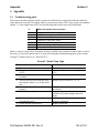
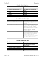
Section 2
Microwave
Catheter
Prostatic
Urethral
Length
Catheter
Color
Scheme
Serial
Number
Tag Color
Serial
Number
Prefix
CTC Advance®
- Short
2.5 to 3.5
cm
Blue Handle
Black Accents
Black
TH
CTC Advance® or
Cooled ThermoCath®
- Standard
3.0 to 5.0
cm
Blue* Handle
White Accents
White
TC
CTC Advance® or
Cooled ThermoCath®
- Long
≥ 4.5 cm
Blue* Handle
Grey Accents
Grey
TF
Targis®
- Short
2.5 to 3.5
cm
White Catheter
Green Handle
Green
AB
Targis®
- Standard
3.0 to 5.0
cm
White Catheter
White Handle
Blue
AB
Table 2-1. Microwave Catheter Identification
*NOTE: A dark blue handle is Cooled ThermoCath®, the light blue is the CTC Advance®.
Note: The serial number label is attached to the cable of the microwave catheter near the
connection to the patient cable.
Caution: The microwave antenna on the distal end of the microwave
catheter may break if you bend it. Do not grab the microwave catheter or
squeeze it in the area of the antenna or the shaft. The optical fiber located in the
flexible shaft may be broken if it is clamped.
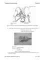
4. Open the package containing the microwave catheter (Figure 2-7). Test the location
balloon by filling it with 10 cc of sterile water and examining it for leaks.
Part Number 250023-001 Rev G
33 of 143
Section 2
Treatment Session Setup
Figure 2-7. CTC Advance® Microwave Catheter
Note: For this user manual, the representative microwave catheter is the CTC Advance®
Microwave Catheter.
5. Lubricate the microwave catheter with a water-based lubricant or local anesthetic.
6. Insert the microwave catheter into the patient’s urethra until the location balloon is
completely in the bladder. Align the microwave catheter so that the urine drainage port
is pointed toward the patient’s posterior and the coolant tubing is in an anterior
orientation.
Warning: Avoid excessive force when pulling back on the microwave
catheter to seat the balloon at the bladder neck. Excessive force could injure the
patient or damage the catheter.
7. Inflate the location balloon with 10 cc of sterile water. Pull back on the microwave
catheter until mild resistance is felt.
8. Flush the urine drainage lumen with 4-5 cc of sterile water. Insert a catheter plug (to
retain bladder anesthetic, if used), or attach a urine drainage bag.
Note: Failure to flush the urine drainage lumen may cause system calibration errors.
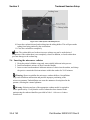
9. Position the microwave catheter properly by pulling on it until the balloon is seated in
the bladder neck, locating the microwave antenna within the preprostatic urethra (Figure
2-8). Verify microwave catheter position with the ultrasound probe.
Warning: Proper position of the location balloon is essential to patient
safety.
34 of 143
Part Number 250023-001 Rev G
Treatment Session Setup
Section 2
Figure 2-8. Inserted Microwave Catheter and Standard RTU
10. If the microwave catheter position is not acceptable, it may have to be rotated or
reinserted. Push the catheter through the urethra until the tip and the location balloon is
completely in the bladder. Rotate the microwave catheter, and then pull back until you
feel mild resistance (Figure 2-8). Verify the microwave catheter position with
ultrasound prior to proceeding with rectal unit insertion.
2.7 Inserting the Single-Use Standard RTU
1. Verify the patient has received an enema.
2. Open the package, and remove the rectal unit (Figure 2-9).
Figure 2-9. Standard RTU
3. Deflate the rectal balloon completely by attaching a 60 cc syringe to the inflation port
and withdrawing air. The balloon should be deflated with the temperature sensors
midline.
4. Lubricate the rectal balloon with a water-based lubricant (e.g. K-Y® Jelly), and insert
the balloon into the rectum with the index finger. Inserting the balloon can be done with
the patient on his side or supine with knees bent. The temperature sensors must be
oriented toward the prostate. The orientation flag must be pointing toward the patient’s
posterior.
Warning: The rectal unit must be positioned properly to ensure correct
temperature sensing.
Part Number 250023-001 Rev G
35 of 143
Section 2
Treatment Session Setup
5. Inflate the rectal balloon by injecting 120 cc of air into the inflation port, located on the
proximal end of the rectal unit. Adjust air volume for patient comfort to no less than 80
cc. Close the valve on the inflation port. 6. Re verify proper positioning of the rectal unit by observing that the orientation flag,
located on the balloon, is facing away from the prostate and toward the patient’s
posterior.
Warning: A minimum of 80 cc of air in the standard RTU rectal balloon is
required to maintain contact between the temperature sensors and the rectal wall.
Warning: This visual reference should be made every 5 to 10 minutes
throughout the treatment to verify the proper position of the rectal unit. Failure
to properly orient the rectal unit during treatment can result in patient injury (e.g.
fistula or scrotal burn).
2.8 Inserting the RTU Plus Reusable Handle and Single-Use Balloon
1. Verify the patient has received an enema.
2. Open the package for the RTU Plus Reusable Handle, or obtain a disinfected RTU Plus
Handle from a previous treatment (Figure 2-10). The RTU Plus Handle with the
temperature sensors should not be used in more than 30 treatments.
Figure 2-10. RTU Plus Reusable Handle
3. Open the package for a RTU Plus Disposable Balloon (Figure 2-11).
36 of 143
Part Number 250023-001 Rev G
Treatment Session Setup
Section 2
Figure 2-11. RTU Plus Disposable Balloon
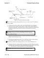
4. Insert the temperature sensor strip into the sensor channel of the disposable balloon, as
shown in Figure 2-12. Orient the sensors toward the outside of the balloon, and do not
bend the temperature strip significantly. The temperature sensor strip should extend to
the distal end of the channel, and the temperature sensor channel should be aligned with
the top side of the handle.
Figure 2-12. Inserting the Temperature Sensor Strip
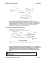
5. Seat the balloon inflation tubing in the inflation tubing channel located in the base of the
rectal unit handle. The locating key should snap into place within the handle key hole; if
not, reorient/reassemble the device. The proper positioning of the temperature sensor
strip in the disposable balloon is assured by the locating key/handle interaction (Figure
2-13).
Part Number 250023-001 Rev G
37 of 143
Section 2
Treatment Session Setup
Figure 2-13. Proper Positioning of the Temperature Sensor Strip
6. Slide the protective sheath down from the balloon, and pull it over the handle as shown
in Figure 2-14.
Figure 2-14. Assembled RTU Plus with Deployed Sheath
7. Attach a syringe to the inflation port, and inflate the balloon with approximately 90 cc
of air to verify that no leaks are present. Remove all air to ensure that the balloon is
completely deflated. Then, remove the syringe before proceeding to step 8.
8. Lubricate the balloon area with a water-based lubricant (e.g. K-Y Jelly).
Warning: The rectal unit must be positioned properly to ensure correct
temperature sensing.
9. Insert the balloon slowly into the rectum using the semirigid tubing to guide placement.
This can be done by initially grasping the sensor/support tubing in the middle of the
balloon area and slowly introducing the balloon into the rectum. Then, move the
guiding hand back to the handle. Slowly advance the balloon while grasping the handle
until the entire balloon is inserted. Inserting the balloon can be done with the patient on
his side or supine with knees bent.
Note: The rectal temperature sensors must be oriented toward the prostate: The RTU
Plus Reusable Handle is labeled anterior and posterior to help with placement.
38 of 143
Part Number 250023-001 Rev G
Treatment Session Setup
Section 2
10. Verify rectal unit orientation by confirming that the inflation tubing channel in the rectal
unit handle (Figure 2-10) is facing towards the patient’s posterior. Therefore, with the
patient supine, the handle base would be against the treatment table surface with the
Urologix® logo visible on both sides of the handle. This orientation ensures that the
temperature sensors of the RTU Plus are pointed towards the patient’s anterior rectal
wall nearest the prostate.
Warning: This visual reference should be made every 5 to 10 minutes
throughout the treatment to verify the proper position of the rectal unit. Failure to
properly orient the rectal unit during treatment can result in patient injury (e.g.
fistula or scrotal burn).
Warning: A minimum of 70 cc of air in the RTU Plus rectal balloon is
required to maintain contact between the temperature sensors and the rectal wall.
11. Inflate the rectal balloon by injecting 90 cc of air into the inflation port, located on the
proximal end of the rectal unit. Adjust the air volume for patient comfort to 70 cc.
Remove the syringe.
12. The physician must confirm the proper positioning of the rectal unit prior to proceeding.
Note: When using an RTU Plus Reusable Handle, the Protocol screen will display the
number of times the handle has been used and the number of remaining uses. The RTU Plus
Reusable Handle should not be used in excess of 30 times.
2.9 Connecting the Microwave Catheter and Rectal Unit to the CoolWave®
Control Unit
Warning: Excessive elevation of the patient torso may put additional
pressure on the rectal unit, resulting in increased patient discomfort and higher
rectal temperatures.
1. If the rectal unit was placed in the rectum while the patient was on his side, reposition
the patient supine, with head and shoulders at no greater than a 20º angle. This position
relieves pressure on the rectal unit and increases patient comfort.
2. Pull gently on the microwave catheter to reseat the location balloon at the bladder neck
in case it moved during rectal unit insertion. If ultrasound was not used to verify
microwave catheter position prior to rectal unit insertion, use ultrasound at this point to
verify proper microwave catheter position.
3. Position the rectal unit cable underneath the microwave catheter holder. Secure the
microwave catheter into the microwave catheter holder, with the cooling lines in the
anterior position, once the microwave catheter position is acceptable. If desired, position
the patient’s legs on the knee cushions that come with the Patient Comfort Kit. Refer to
Section 5.4, Patient Comfort Kit, to view the accessories in the kit.
Part Number 250023-001 Rev G
39 of 143
Section 2
Treatment Session Setup
4. Make a mark, with a permanent marker or tape, on the microwave catheter at the
meatus. Use this mark as a visual reference to confirm proper microwave catheter
position.
Warning: This visual reference should be checked every 5-10 minutes
throughout the treatment to verify the proper position of the microwave catheter
and of the rectal unit.
5. Secure the microwave catheter fiber optic and microwave connectors to the patient
connection cable housing (Figure 2-15).
Figure 2-15. Connected Microwave Catheter and Rectal Unit
6. Connect the male luer fitting of the microwave catheter coolant tubing to the female luer
fitting of the coolant bag tubing. Then, flush the female luer fitting of the microwave
catheter coolant tubing with 4-5 cc of sterile water, and connect the microwave catheter
to the coolant bag. This will preinflate the microwave catheter cooling channel.
Warning: Do not touch the antenna cable or the catheter handle while
microwave power is ON. Touching the cable or the handle while microwave
power is ON can cause burns. To prevent burns during treatment, isolate the
antenna cable and the catheter handle away from the patient's legs.
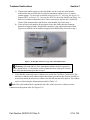
7. To reduce the risk of burns, isolate the antenna cable (Figure 2-15) and the catheter
handle away from the patient’s legs:
• Using the microwave catheter holder from the Patient Comfort Kit to secure the
microwave catheter/antenna cable/handle location (Figure 2-16),
•
If the microwave catheter holder is not available, place the antenna cable and handle
between the patient’s legs―not over the legs―and use a towel to isolate the legs
and keep them from moving.
•
Then, verify that the cable and handle are sufficiently isolated from the patient prior
to beginning treatment
40 of 143
Part Number 250023-001 Rev G
Treatment Session Setup
Section 2
Figure 2-16. Isolate the Antenna Cable and Catheter Handle Using the Microwave Catheter Holder
8. Connect the rectal unit connector to the patient connection cable housing (Figure 2-17).
Figure 2-17. Patient Connection Cable Housing
9. If not already completed, attach a urine drainage bag to the urine drainage port of the
microwave catheter.
Part Number 250023-001 Rev G
41 of 143
Section 2
Treatment Session Setup
10. Proceed to Section 3, Treatment Instructions, for information on how to perform a
Cooled ThermoTherapy™ Treatment.
42 of 143
Part Number 250023-001 Rev G
Treatment Instructions
Section 3
3 Treatment Instructions
3.1 System Navigation and Screen Overview
This section provides the information needed to navigate the CoolWave® Control Unit as well as an
overview of the screens, including demonstration mode. Please read this section prior to using the
CoolWave Control Unit for the first time.
3.1.1
System Navigation
The CoolWave Control Unit includes a touchscreen monitor. This touchscreen monitor makes it
easy to move around in the CoolWave Control Unit. Simply use your finger to gently press on the
buttons on the screen. You will hear a “tick” sound when you press a button. You may also notice
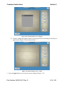
that a “pressed” button looks flat on the screen while a “nonpressed” button looks more 3dimensional (Figure 3-1).
Figure 3-1. Pressed and Nonpressed Buttons
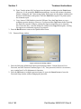
Some screens require entering information into a data field (Figure 3-2). Touch the screen in the
desired data field, and when the cursor appears in that data field, use the keyboard to enter the
requested information.
Note: You only need to touch the data field once with your finger to activate the operation of
that field.
Figure 3-2. Data Field
When you are done entering information, touch the screen in the desired data field or use the TAB
key (or the TAB and SHIFT keys) to move from one data field to the next data field.
Part Number 250023-001 Rev G
43 of 143
Section 3
Treatment Instructions
Press the TAB key to move
the cursor ahead to the next
data field.
TAB KEY
SHIFT KEY
TAB KEY
Press and hold the SHIFT
key while pressing the TAB
key to move the cursor back
to the previous data field.
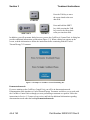
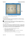
In addition, you will encounter dialog boxes as you use the CoolWave® Control Unit. A dialog box
provides additional information or instruction (Figure 3-3). When a dialog box appears on the
screen, read the information or follow the instructions before continuing with the Cooled
ThermoTherapy™ Treatment.
Figure 3-3. Example of a CoolWave Control Unit Dialog Box
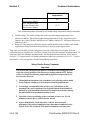
Demonstration mode
If you are training on the CoolWave Control Unit, you will be in demonstration mode.
Demonstration mode simulates a Cooled ThermoTherapy Treatment and allows you to work with
the CoolWave Control Unit as though you were performing a treatment on a patient. Follow the
instructions in Section 3, Treatment Instructions, and look for additional information regarding
demonstration mode under the heading Demonstration mode.
44 of 143
Part Number 250023-001 Rev G
Treatment Instructions
3.1.2
Section 3
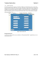
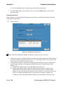
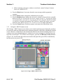
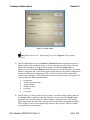
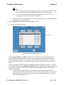
Screen Overview
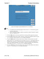
The following information appears on all of the CoolWave® Control Unit screens, except for the
Login screen: date, time, screen name, user name, and software version. Each screen, except for the
Login screen, also contains access to the CoolWave Control Unit help feature, which contains the
CoolWave Control Unit User Manual. In addition, on the treatment screens, you will find a Notes
button. This button provides access to the notes feature where you can enter patient or treatment
information (Figure 3-4).
Figure 3-4. Screen Overview
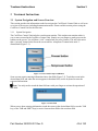
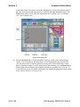
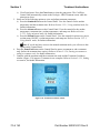
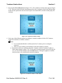
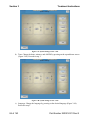
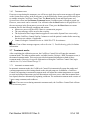
Demonstration mode
A yellow bar at the top of the screen, with the text “Demonstration Mode,” signals that you are in
demonstration mode.
Part Number 250023-001 Rev G
45 of 143
Section 3
Treatment Instructions
Figure 3-5. Example of a Treatment Screen in Demonstration Mode
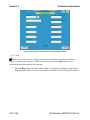
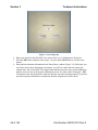
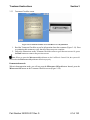
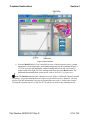
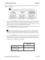
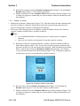
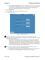
3.1.2.1 Help
Note: If you receive an error message on the System Calibration screen, the System Error
screen, or while on the Urologix® - BPH Treatment screen, press the Help button to view
information about the displayed error message.
1. Press the Help button. The Help window (Figure 3-6) appears containing the appropriate
help information based on your location in the CoolWave® Control Unit System software.
46 of 143
Part Number 250023-001 Rev G
Treatment Instructions
Section 3
Figure 3-6. Help Window
2. Press the up and down arrows to scroll through the Help window. Or, press the Back,
Forward, Contents, Glossary, or Close buttons to move through the help feature.
• Press the Back button: Move back through the help topics viewed recently.
• Press the Forward button: Move forward through the help topics viewed recently.
• Press the Contents button: View the CoolWave® Control Unit User Manual table of
contents.
• Press the Glossary button: View the CoolWave® Control Unit User Manual index
glossary.
• Press the Close button: Close the Help window.
3.1.2.2 Notes
1. Press the Notes button. The Notes dialog box appears (Figure 3-7).
Part Number 250023-001 Rev G
47 of 143
Section 3
Treatment Instructions
Figure 3-7. Notes Dialog Box
2. Enter your initials in the data field. You can use from 1 to 3 alphanumeric characters.
3. Press the OK button, and proceed to step 4. Or, press the Cancel button to exit the notes
feature.
4. Enter patient treatment information in the Notes Entry window (Figure 3-8). Each time you
access the notes feature throughout a treatment, you will see a date and time stamp, the
elapsed time, and your initials. The elapsed time indicates the time since system calibration
started, when you are on the System Calibration screen. Or, when on the Urologix® - BPH
Treatment screen, the elapsed time indicates the time since the treatment started. If you have
not started system calibration or a treatment, then the elapsed time will be 00:00.
48 of 143
Part Number 250023-001 Rev G
Treatment Instructions
Section 3
Figure 3-8. Notes Entry Window
5. Press the Close button when finished
3.2 CoolWave® Control Unit setup
Warning: Do not move the CoolWave Control Unit while the electrical cord is connected to a
power source.
Note: Turn ON the Control Unit at least 5 minutes before the treatment begins to allow the
system to warm up.
3.2.1
Turn ON the Control Unit
Press the ON/OFF power switch (located on the back of the unit, see Figure 1-6. ON/OFF power
switch) to the "I" position. The CoolWave Control Unit turns ON and proceeds with its startup
routine. The Login screen appears.
Part Number 250023-001 Rev G
49 of 143
Section 3
3.2.2
Treatment Instructions
Login screen
Figure 3-9. Login Screen
Notes:
• You can turn OFF the CoolWave® Control Unit at this point during system startup without
losing any stored data.
•
Entering an invalid password returns you to the Login screen.
1. Press the Login button (Figure 3-9). The User Login window appears (Figure 3-10).
50 of 143
Part Number 250023-001 Rev G
Treatment Instructions
Section 3
Figure 3-10. User Login Window
2. Determine if you are a new user or a current user. If you are a new user, proceed to step 3. If
you are a current user, proceed to step 10.
3. Press the New User button. The Create New User window appears (Figure 3-11).
4. Enter your full name in the Full Name data field.
Figure 3-11. Create New User Window
5. Enter a user name in the User Name data field. Your user name, which is case sensitive, may
contain from 3 to 20 alphanumeric characters.
6. Enter a password in the Password data field. Your password, which is case sensitive, may
contain from 3 to 20 alphanumeric characters.
7. Re-enter your password in the Password Confirm data field.
Part Number 250023-001 Rev G
51 of 143
Section 3
Treatment Instructions
8. Press the OK button to return to the Login screen. Your user name and password are saved.
Proceed to step 9. Or, press the Cancel button to exit without creating a new user name and
password.
9. Press the Login button (Figure 3-9). The User Login window appears (Figure 3-12).
Figure 3-12. User Login Window
10. Enter your user name, which is case sensitive, in the User Name data field.
11. Enter your password, which is case sensitive, in the Password data field.
12. Press the OK button to go to the Main Menu screen. Or, press the Cancel button to return to
the Login screen.
Demonstration mode
To enter demonstration mode, type the following word as the user name and the password: Demo.
The capitalization of the letter “D” in Demo is required.
3.2.3
Main Menu Screen
After logging into the CoolWave® Control Unit, your user name and the software version appears
at the top of the Main Menu screen (Figure 3-13).
52 of 143
Part Number 250023-001 Rev G
Treatment Instructions
Section 3
Figure 3-13. Main Menu Screen
Note: Turning OFF the Control Unit at this point during system startup does not cause a loss of
stored data.
1. Press the Treatment button to proceed with a treatment. Refer to Section 3.3, Cooled
ThermoTherapy™ , for further information.
2. Press the Options button to view CoolWave Control Unit system options. Refer to Section
3.5, CoolWave Control Unit options, for further information.
3. Press the Log Out button to return to the Login screen. Refer to Section 3.2.2, Login screen,
for further information.
3.3 Cooled ThermoTherapy™ Procedure
This section of the user manual steps you through a Cooled ThermoTherapy™ Procedure for
Benign Prostatic Hyperplasia (BPH) using the CoolWave® Control Unit. As you proceed through
the various treatment screens described in this section, beginning with the Patient Information
screen, you will be entering data and selecting treatment protocols. You may also be modifying the
following treatment parameters:
•
•
Treatment time: The treatment time reflects the length of time for a Cooled ThermoTherapy
Procedure. The default treatment time is 28 minutes and 30 seconds.
Coolant setting: The coolant setting reflects the set point (target) temperature at which the
coolant flows through the microwave catheter. The following table includes the default
coolant setting temperature for the Targis® Microwave Catheter and the Cooled
ThermoCath® Microwave Catheter and the CTC Advance® Microwave Catheter:
Part Number 250023-001 Rev G
53 of 143
Section 3
Treatment Instructions
Default coolant setting
temperature
Targis®
Microwave Catheter
CTC Advance® and
Cooled ThermoCath®
Microwave Catheter
8°C
15°C
The coolant temperature will ramp to its coolant setting temperature during a treatment.
•
•
Urethra setting: The urethra setting reflects the set point (target) temperature of the
microwave catheter. The default urethra setting temperatures for the Targis Microwave
Catheter, the Cooled ThermoCath Microwave Catheter, and the CTC Advance® Microwave
Catheter are 40°C.
Ramp rate: The ramp rate reflects the speed at which the Microwave Catheter and coolant
temperatures change from their current values to their set point (target) values.
Then, once you reach the System Calibration screen, the calibration process begins. After the
calibration process completes, the CoolWave Control Unit enters the automatic treatment mode. To
learn more about the automatic treatment mode, and the manual treatment mode, please refer to
Section 3.7, Treatment modes, for further information. Otherwise, proceed to Section 3.3.1, Patient
Information screen, to begin the Cooled ThermoTherapy procedure.
Safety Checks During Treatment
Important
It is critical that, throughout the patient’s treatment, the treating physician
verify the correct position of the microwave catheter and the RTU. Patient
safety is at risk if the following simple and straightforward procedures are
not correctly observed.
1. Throughout the duration of the treatment, verify that the position mark
on the catheter remains at a fixed distance from the penile meatus.
2. It is strongly recommended that at least every 5-10 minutes of the
treatment, the correct position of the location balloon in the bladder be
checked by transabdominal ultrasound. Document the action by placing
the ultrasound in the permanent patient record.
3. Check the correct positioning of the rectal unit at least every 5 to 10
minutes to ensure the rectal unit has not moved.
4. Always immediately check microwave catheter and rectal unit
placement if the patient complains of any abnormal or sudden increase
in pain. Pause the treatment if the patient complains of serious pain.
54 of 143
Part Number 250023-001 Rev G
Treatment Instructions
Section 3
5. Observe the treatment parameters for sudden changes in readings,
especially decreases in temperatures that might indicate a sensor has
moved from its previous position.
Table 3-1. Safety Checks During Treatment
3.3.1
Patient Information screen
Figure 3-14. Patient Information Screen
1. Enter patient information (Figure 3-14). Data fields marked with a bullet require information
before proceeding with the treatment.
• Patient Name: Enter up to 20 alphabetic characters for the first name, 1 alphabetic
character for the middle initial, and up to 30 alphabetic characters for the last name.
• Patient ID: Enter the patient’s hospital medical record number or clinic ID. You can
enter up to 20 alphanumeric characters.
• Institution: Enter the name of the hospital or clinic. You can enter up to 20 alphanumeric
characters.
• Age: Enter the patient’s age.
• Quality of Life: Enter the quality of life index.
• Prostate Specific Antigen (ng/mL): Enter the prostate specific antigen level (ng/mL).
• International Prostate Symptom Score: Enter the international prostate symptom score or
the AUA symptom score.
• Qmax (mL/s): Enter the maximum flow rate (mL/s).
• Urethra Length (cm): Enter the urethra length (cm). The urethra length must be at least
2.5 cm.
• Prostate Volume (mL): Enter the prostate volume (mL).
Part Number 250023-001 Rev G
55 of 143
Section 3
•
Treatment Instructions
Post Void Residuals (mL): Enter the postvoid residual volume (mL).
2. Press the Next button to go to the next screen. Or, press the Back button to return to the
previous screen.
Demonstration mode
Enter “dummy” text on the Patient Information screen. Be sure to include information in the data
fields marked with a bullet.
3.3.2
Protocol screen
Figure 3-15. Example of a Protocol Screen
Note: The RTU Plus Reusable Handle should not be used in excess of 30 times.
1. Connect the microwave catheter and the rectal unit to the patient connection cable housing if
you have not done so already (refer to Section 2.9, Connecting the Microwave Catheter and
Rectal Unit to the CoolWave® Control Unit).
2. Verify that the CoolWave Control Unit automatically inserted the microwave catheter and
rectal unit serial numbers in the appropriate data fields in step 1 on the Protocol screen
(Figure 3-15).
a) If both serial numbers appear in the data fields, proceed to step 3.
b) If both serial numbers appear in the data fields, but the microwave catheter serial
number indicates that a used catheter is connected to the system, a caution symbol
appears. To use a new microwave catheter, refer to Section 2.6, Inserting the microwave
catheter, for further information. Once a new microwave catheter is in place, the
CoolWave Control Unit automatically reads the new serial number. Proceed to step 3.
56 of 143
Part Number 250023-001 Rev G
Treatment Instructions
Section 3
c)
If both serial numbers appear in the data fields, but the rectal unit serial number
indicates that the rectal unit has exceeded its maximum number of uses, a caution
symbol appears. To use a new rectal unit, refer to Section 2.7, Inserting the Single-Use
Standard RTU, or Section 2.8 , Inserting the RTU Plus Reusable Handle and Single-Use
Balloon, for further information. Once a new rectal unit is in place, the CoolWave®
Control Unit automatically reads the new serial number. Proceed to step 3.
d) If one or both serial numbers do not appear in the data fields, then the treatment
protocol list appears blank. Readjust the connectors, tags, and serial number labels
(Figure 3‐16) until the serial number(s) appear in the data field(s). Proceed to step 3.
Figure 3-16. Readjust connectors, tags, and serial number labels
Warning: Selection and use of the appropriate catheter model is required to
assure patient safety. Verify that the correct catheter has been read by the Control
Unit using the instructions provided in step 3.
3. Verify that the correct microwave catheter was read by the CoolWave Control Unit. The
microwave catheter serial number and the description provided on the Protocol CoolWave
screen must match the microwave catheter selected and inserted in the patient. The catheter
can be verified using the information provided in Table 3-2.
Note: The serial number label is attached to the cable of the microwave catheter near the
connection to the patient cable. See Figure 3-16.
Part Number 250023-001 Rev G
57 of 143
Section 3
Treatment Instructions
Microwave
Catheter
Prostatic
Urethral
Length
Catheter
Color
Scheme
Serial
Number
Tag Color
Serial
Number
Prefix
CTC Advance®
- Short
2.5 to 3.5
cm
Blue Handle
Black Accents
Black
TH
3.0 to 5.0
cm
Blue* Handle
White Accents
White
TC
≥ 4.5 cm
Blue* Handle
Grey Accents
Grey
TF
Targis®
- Short
2.5 to 3.5
cm
White Catheter
Green Handle
Green
AB
Targis®
- Standard
3.0 to 5.0
cm
White Catheter
White Handle
Blue
AB
CTC Advance® or
Cooled ThermoCath®
- Standard
CTC Advance® or
Cooled ThermoCath®
- Long
Table 3-2. Microwave catheter identification
*NOTE: A dark blue handle is Cooled ThermoCath®, the light blue is the CTC Advance®.
4. Select the desired treatment protocol, in step 2 on the Protocol screen, for your patient, and
then press the treatment protocol name (Figure 3-15). Protocols can vary depending on the
microwave catheter in use and user preference. The description next to each protocol defines
first the urethra temperature, second the coolant temperature, and third the ramp rate; all
treatment times default to 28 minutes and 30 seconds, though that time can be modified
from the standard mode or advanced mode CoolWave® Control Panel on the Urologix® BPH Treatment screen. In addition, a custom protocol is user defined and can be modified.
To modify a custom protocol, proceed to step 4. Otherwise, proceed to step 7 to continue
with the treatment.
5. Select a custom protocol, if you have not done so already, by pressing on the treatment
protocol name. Then, press the Modify button (Figure 3-17).
58 of 143
Part Number 250023-001 Rev G
Treatment Instructions
Section 3
Figure 3-17. Example of Protocol screen - modify
6. Adjust the urethra setting, coolant setting, and ramp rate (Figure 3-18), as desired:
Figure 3-18. Example of treatment protocol - modify
Note: The treatment timer runs when the following conditions occur:
Part Number 250023-001 Rev G
59 of 143
Section 3
Treatment Instructions
Table 3-3 Treatment Timer algorithms
a)
Urethra setting: Press the up and down arrows to adjust the urethra setting temperature
in 0.5°C increments. The default urethra setting temperatures for the Targis Microwave
Catheter and the Cooled ThermoCath microwave catheter and the CTC Advance®
Microwave Catheter are 40°C.
b) Coolant setting: Press the up and down arrows to adjust the coolant setting temperature
in 0.5°C increments. The following table includes the default coolant setting
temperature for the Targis Microwave Catheter, the Cooled ThermoCath Microwave
Catheter and the CTC Advance® Microwave Catheter:
Default coolant setting
temperature
Targis®
Microwave Catheter
CTC Advance® and
Cooled ThermoCath®
Microwave Catheter
8°C
15°C
The coolant temperature will ramp to its coolant setting temperature during a treatment.
c)
Ramp rate: Press the up and down arrows to select the ramp rate: slow / medium / fast,
(approximately 12 / 8 / 4 minutes)
7. Press the OK button to save the new treatment parameter(s). Or, press the Cancel button to
return to the original treatment parameters for that protocol.
8. Press the Next button to go to the next screen. Or, press the Back button to return to the
previous screen.
Demonstration mode
The CoolWave® Control Unit will automatically fill in the microwave catheter serial number and
rectal unit serial number data fields with simulated information. Start with step 4 above.
60 of 143
Part Number 250023-001 Rev G
Treatment Instructions
3.3.3
Section 3
Treatment Checklist screen
Figure 3-19. Treatment Checklist screen and Microwave Off pushbutton
1. Read the Treatment Checklist screen for information about the treatment (Figure 3-19). Prior
to continuing this treatment, verify that all of these steps are complete.
2. Follow the instructions on the Treatment Checklist screen to go to the next screen. Or, press
the Back button to return to the previous screen.
Note: When you press the Microwave Off pushbutton on the CoolWave® Control Unit, the system will
confirm that the Microwave Off pushbutton functions properly.
Demonstration mode
When in demonstration mode, you will not press the Microwave Off pushbutton. Instead, press the
Microwave Off button on the Treatment Checklist screen (Figure 3-20).
Part Number 250023-001 Rev G
61 of 143
Section 3
Treatment Instructions
Figure 3-20. Treatment Checklist screen - Demonstration mode
3.3.4
System Calibration screen
Figure 3-21. System Calibration screen
1. Wait while the Control Unit proceeds through a calibration process (can take up to 7
minutes) (Figure 3-21):
62 of 143
Part Number 250023-001 Rev G
Treatment Instructions
•
•
•
•
•
Section 3
Temperature stabilization
Rectal unit calibration
Urethra temperature calibration
Pump calibration
Frequency calibration
As each item in the list completes calibration, a checkmark appears in the box next to that
item.
a) Calibration completes successfully: Proceed to Section 3.3.5, Urologix® - BPH
Treatment screen, if the Control Unit completes the calibration process and
automatically goes to the Urologix - BPH Treatment screen.
b) Calibration does not complete successfully: An error message appears on the System
Calibration screen. Proceed to step 2.
c) Calibration needs to stop due to user needs: Press the Cancel button to stop the
calibration process. An error message appears on the System Calibration screen.
Proceed to step 2.
2. Read the System Calibration screen (Figure 3-22), and use the error message to resolve the
problem. In addition, use one of the actions listed on the System Calibration screen to help
you determine what to do next.
Figure 3-22. System Calibration Screen - Error Message
Notes:
• If a calibration error message appears, refer to Section 5.1, Troubleshooting guide,
for further information.
Part Number 250023-001 Rev G
63 of 143
Section 3
•
Treatment Instructions
Before replacing a microwave catheter or rectal unit, contact Urologix Customer
Service at 1-888-229-0772.
a)
Press the Help button: Learn more about the error message and the appropriate
response.
b) Press the Retry button: Attempt the calibration process again.
c) Press the Replace button: Replace the microwave catheter or the rectal unit, as needed.
Refer to Section 2.6, Inserting the microwave catheter, Section 2.7, Inserting the SingleUse Standard RTU, or Section 2.8, Inserting the RTU Plus Reusable Handle and SingleUse Balloon, for further information. The CoolWave Control Unit returns you to the
Protocol screen. Refer to Section 3.3.2, Protocol screen, for further information.
d) Press the Cancel button: Exit this treatment, and return to the Main Menu screen.
3.3.5
Urologix® - BPH Treatment screen
The Urologix - BPH Treatment screen allows you to monitor patient progress during the procedure.
If you need to make any adjustments to the treatment parameters, make those adjustments from this
screen. Otherwise, treatment proceeds automatically based on the selected treatment protocol. If a
caution or error occurs during treatment, a caution icon or error icon appears in the blue bar at the
top of the screen (Figure 3-23). If there is an emergency, press the red Microwave Off pushbutton
(Figure 3-24), located under the touchscreen monitor and right of the green LED, to immediately
turn the microwave power OFF.
Figure 3-23. Urologix - BPH Treatment screen
64 of 143
Part Number 250023-001 Rev G
Treatment Instructions
Section 3
Figure 3-24. Microwave Off Pushbutton
1. View treatment data in the Status Panel at the top of the Urologix® - BPH Treatment screen
(Figure 3-23).
• Power: Displays microwave power in watts, measured at the patient connection cable.
When power is ≥1 W, an animated microwave power ON graphic appears and the
amber LED, located to the right of the red Microwave Off pushbutton, lights.
• Coolant: Displays coolant temperature in °C as measured by the Coolant Bag sensor. If
the coolant pump is turned OFF, this reading will gradually approach room temperature.
• Rectal: Displays the warmest of the 5 rectal temperatures in °C.
• Urethra: Displays the urethra temperature in °C.
• Status: Highlights status as pause (treatment OFF), ramp (system preparing for
treatment), treat (treatment ON), or cool (cooldown ON).
• Progress: Displays treatment time (minutes:seconds) elapsed, treatment time
(minutes:seconds) remaining, and energy (kilojoules). Treatment time elapsed, also
referred to as the treatment timer, is defined by the following algorithms:
Table 3-4. Treatment Timer algorithms
Treatment time remaining is calculated by subtracting the current elapsed treatment
time from the treatment time setting. You can tell, from the time remaining, when the
CoolWave® Control Unit will enter cooldown.
2. View treatment details at the left side of the Urologix® - BPH treatment screen.
a) Press the Chart button: View the microwave power, coolant temperature, rectal
temperature, and urethra temperature for this treatment in a scrolling strip chart format
(Figure 3-25). The colors of each trace on the chart correspond to the color of the item
Part Number 250023-001 Rev G
65 of 143
Section 3
Treatment Instructions
in the Status Panel: The white vertical line indicates the current values and the end of
the chart. Press the left and right arrows to scroll left and right through the chart. The
Zoom button allows you to view this information in a 10 minute view, a 30 minute
view, or a 60 minute view.
Figure 3-25. Chart pane
b) Press the Event button: View the treatment event log: events, errors, and warnings
(Figure 3-26). Press the up and down arrows to scroll through the log. You can also
view the current error or warning (listed in priority order, errors first) in the Current
Error or Warning window. To reset current errors and warnings, press the Reset button.
If the system does not return to the treatment and an error remains, refer to Section 5.1,
Troubleshooting guide, for further information. For additional information about system
errors, refer to Section 3.6, System errors.
66 of 143
Part Number 250023-001 Rev G
Treatment Instructions
Section 3
Figure 3-26. Event pane
c)
Press the Detail button: View a detailed overview of the microwave power, coolant
temperature, rectal temperature, and urethra temperature for this treatment (Figure 327). This overview also highlights current warnings and errors: An active error is
marked with a blue light. To reset warnings and errors, press the Reset button. For
additional information about system errors, refer to Section 3.6, System errors.
Note: The Detail button provides a detailed overview of the CoolWave® Control Unit and
its settings. A typical treatment does not require access to this overview. However, you may
need to view this information if an error occurs and does not resolve. At this point, contact
Urologix® Customer Service (1-888-229-0772) to help you resolve any remaining errors.
Part Number 250023-001 Rev G
67 of 143
Section 3
Treatment Instructions
Figure 3-27. Detail pane
3. View treatment data in a diagram format at the right side of the Urologix® - BPH Treatment
screen (Figure 3-28).
Figure 3-28. Treatment diagram
4. Press the Print button, located in the upper right corner of the Urologix - BPH Treatment
screen. Then, select one of the following print options: Print Treatment Report, Print Event
Log, and Clear Print Queue (Figure 3-29). Or, press the Close button to return to the
Urologix - BPH Treatment screen.
68 of 143
Part Number 250023-001 Rev G
Treatment Instructions
Section 3
Figure 3-29. Print window
Note: Refer to Section 4.3, Maintaining the printer, Figure 4-3, for a printer
overview.
a)
Print Treatment Report: Press the Remove Patient Info button (optional) to remove a
patient’s name from a treatment report. A check mark appears in the button. Turn the
printer ON, load paper, if needed, into the printer, and press the Report button.
(However, if you pressed the Report button and paper was not in the printer, the printer
flashes 1 long green and 2 short orange lights. Insert paper into the printer, and press the
Resume/Cancel button on the printer.) The CoolWave® Control Unit automatically
returns to the Urologix® - BPH Treatment screen while the treatment report prints. The
report includes the following information:
• Patient data
• Treatment protocol data
• Treatment data
• Treatment chart
• Event log
•
Case notes b) Print Event Log: Turn the printer ON, load paper, if needed, into the printer, and press
the Events button to print the event log. (However, if you pressed the Events button
and paper was not in the printer, the printer flashes 1 long green and 2 short orange
lights. Insert paper into the printer, and press the Resume/Cancel button on the printer.)
The CoolWave Control Unit automatically returns to the Urologix - BPH Treatment
screen while the event log prints.
Part Number 250023-001 Rev G
69 of 143
Section 3
Treatment Instructions
c)
Clear Print Queue: Press the Clear button to clear the print queue. The CoolWave
Control Unit automatically returns to the Urologix - BPH Treatment screen while the
print queue clears.
5. Select one of the following options to view and adjust treatment parameters:
a) Press the Standard button on the Control Panel: View the controls for the urethra
temperature and the treatment time. Refer to Section 3.3.5.1, Using standard mode, for
further information.
b) Press the Advanced button on the Control Panel: View the controls for the urethra
temperature, treatment time, coolant temperature, and ramp rate. Refer to Section
3.3.5.2, Using advanced mode, for further information.
c) Press the Manual button on the Control Panel: View the controls for microwave power,
coolant pump ON/OFF, coolant temperature, and ramp rate. Refer to Section 3.3.5.3,
Using manual mode, for further information.
Note: If you do not have access to the manual treatment mode, you will not see this
option on the Control Panel.
6. Press the Pause/End button on the Control Panel to pause a treatment or end a treatment
early (before the treatment time expires). Refer to Section 3.3.5.4, Pausing a treatment or
ending a treatment early, for further information.
7. Continue with the treatment until the treatment time ends and the Treatment Cooldown
window (Figure 3-30) appears: Treatment is now complete. Refer to Section 3.3.5.5, Ending
a treatment, for further information.
Figure 3-30. Treatment Cooldown window
70 of 143
Part Number 250023-001 Rev G
Treatment Instructions
Section 3
3.3.5.1 Using standard mode
Figure 3-31. Standard mode
Adjust the urethra setting and treatment time from the Control Panel (Figure 3-31), if desired:
Note: The treatment timer runs when the following conditions occur:
Table 3-5 Treatment Timer algorithms
•
•
Press the Urethra Setting button: Press the up and down arrows to adjust the urethra setting
temperature in 0.5°C increments. The default urethra setting temperatures for the Targis
Microwave Catheter and the Cooled ThermoCath Microwave Catheter and the CTC Advance
Microwave Catheter are 40°C. Press the Close button when done.
Press the Treatment Time button: Press the up and down arrows to adjust the treatment time
in 30 second increments. Press the Close button when done.
Note: In automatic treatment mode, the treatment time is limited to 28 minutes and 30 seconds
for the Cooled ThermoCath Microwave catheter and from 28 minutes and 30 seconds to 60 minutes
for the Targis Microwave catheter.
Part Number 250023-001 Rev G
71 of 143
Section 3
Treatment Instructions
Figure 3-32. Example of a treatment parameter control panel
3.3.5.2 Using advanced mode
Figure 3-33. Advanced mode
72 of 143
Part Number 250023-001 Rev G
Treatment Instructions
Section 3
Adjust the urethra setting, treatment time, coolant setting, and ramp rate from the Control Panel
(Figure 3-33), if desired:
Note: The treatment timer runs when the following conditions occur:
•
•
Press the Urethra Setting button: Press the up and down arrows to adjust the urethra setting
temperature in 0.5°C increments. The default urethra setting temperatures for the Targis
Microwave Catheter and the Cooled ThermoCath Microwave Catheter and the CTC Advance
Microwave Catheter are 40°C. Press the Close button when done.
Press the Treatment Time button: Press the up and down arrows to adjust the treatment time
in 30 second increments. Press the Close button when done.
Note: In automatic treatment mode, the treatment time is limited to 28 minutes and 30
seconds for the Cooled ThermoCath Microwave Catheter and CTC Advance Microwave
Catheter from 28 minutes and 30 seconds or 60 minutes for the Targis Microwave catheter.
•
Press the Coolant Setting button: Press the up and down arrows to adjust the coolant setting
temperature in 0.5°C increments. The following table includes the default coolant setting
temperature for the Targis® Microwave Catheter and the Cooled ThermoCath® Microwave
Catheter and CTC Advance Microwave Catheter:
Default coolant setting
temperature
Targis®
Microwave Catheter
CTC Advance® and
Cooled ThermoCath®
Microwave Catheter
8°C
15°C
Part Number 250023-001 Rev G
73 of 143
Section 3
Treatment Instructions
The coolant temperature will ramp to its coolant setting temperature during a treatment.
Press the Close button when done.
•
Press the Ramp Rate button: Press the up and down arrows to select the ramp rate: slow,
medium, fast. Press the Close button when done.
Figure 3-34. Example of a treatment parameter control panel
3.3.5.3 Using manual mode
When the manual treatment mode is active, the interval timer will appear on the Status Panel. This
timer indicates the amount of time elapsed since you last adjusted microwave power and can be
used to help you in timing a manual treatment. Refer to Section 3.7.2, Manual treatment mode, for
further information on using the manual treatment mode.
Note: If you do not have access to the manual treatment mode, you will not see this option on
the Control Panel.
74 of 143
Part Number 250023-001 Rev G
Treatment Instructions
Section 3
Figure 3-35. Manual mode
1. Select “Yes” or “No” when the Enter Manual Mode dialog box appears. Proceed to step 2 if
entering the manual treatment mode (selecting “No” returns you to the Urologix® - BPH
Treatment screen).
2. Adjust the power setting, pump ON/OFF, coolant setting, and ramp rate from the Control Panel
(Figure 3-35), if desired:
a) Press the Power Setting button: Press the up and down arrows to adjust the microwave
power setting (from 0.0 W to 60.0 W for a Targis® and CTC Advance® Short
Microwave Catheters, and from 0.0 W to 75.0 W for a Cooled ThermoCath® and CTC
Advance® Standard and Long Microwave Catheters) in 1 W increments. Press the
Close button when done.
b) Press the Pump On/Off button: Press the up and down arrows to turn the coolant pump
ON or OFF. In addition, if microwave power was ON when turning the pump OFF,
microwave power will automatically turn OFF as well. Press the Close button when
done.
c) Press the Coolant Setting button: Press the up and down arrows to adjust the coolant
setting temperature in 0.5°C increments. The following table includes the default
coolant setting temperature for the Targis Microwave Catheter and the Cooled
ThermoCath Microwave Catheter:
Default coolant setting
temperature
Targis Microwave
Catheter
CTC Advance and
Cooled ThermoCath
Microwave Catheters
Part Number 250023-001 Rev G
8°C
15°C
75 of 143
Section 3
Treatment Instructions
The coolant temperature will ramp to its coolant setting temperature during a treatment.
Press the Close button when done.
d) Press the Ramp Rate button: Press the up and down arrows to select the ramp rate:
slow, medium, fast. Press the Close button when done.
Figure 3-36. Example of a treatment parameter control panel
3. Exit manual treatment mode by pressing the Standard button or the Advanced button from the
Control Panel. The Control Unit will return to the automatic treatment mode.
3.3.5.4 Pausing a treatment or ending a treatment early
1. Press the Pause/End button from the Control Panel to pause the treatment and turn OFF
microwave power.
2. Press the Resume button to resume treatment (Figure 3-37). To end treatment and go to
cooldown, proceed to step 3.
Figure 3-37. Resume Treatment dialog box
76 of 143
Part Number 250023-001 Rev G
Treatment Instructions
Section 3
3. Press the Go To Cooldown button (Figure 3-37). The cooldown 5-minute timer appears (Figure
3-38). This timer shows the time remaining until the end of cooldown, which also indicates how
much time has passed since the microwave power was turned OFF (with the coolant pump still
running).
Figure 3-38. Treatment Cooldown window
4. Select one of the following options in cooldown: remain in cooldown for the full 5 minutes,
resume the treatment, or end the cooldown.
Notes:
• It is recommended that the cooldown phase last 5 minutes prior to exiting the
treatment.
• Once you exit cooldown, the treatment is done and cannot be resumed. a) Remain in cooldown: Cooldown ends after 5 minutes, and the Treatment Cooldown End window appears (Figure 3-39). If you need to resume treatment, proceed to step 4b.
Or, you can exit the treatment. Press the Exit button. A dialog box appears to confirm
that you want to exit, and therefore end, this treatment.
Figure 3-39. Treatment Cooldown - End window
Part Number 250023-001 Rev G
77 of 143
Section 3
Treatment Instructions
b) Resume the treatment: Press the Resume Treatment button (Figure 3-38) and then the
Resume button (Figure 3-37) to resume the treatment.
c) End the cooldown: Press the Cooldown End button to end the cooldown (Figure 3-38).
A dialog box appears to confirm that you want to end the cooldown, and therefore end,
this treatment.
3.3.5.5 Ending a treatment
1. Monitor the cooldown 5-minute timer (Figure 3-30). This timer shows the time remaining until
the end of cooldown, which also indicates how much time has passed since the microwave
power was turned OFF (with the coolant pump still running).
2. Select one of the following options in cooldown: remain in cooldown for the full 5 minutes,
reset the 5-minute cooldown timer, or end the cooldown.
Notes:
• It is recommended that the cooldown phase last 5 minutes prior to exiting the
treatment.
• Once you exit cooldown, the treatment is done and cannot be resumed.
a)
Remain in cooldown: Cooldown ends after 5 minutes, and the Treatment Cooldown End window appears (Figure 3-40). If you need to reset the 5-minute cooldown timer,
proceed to step 2b. Or, you can return to the Urologix® - BPH Treatment screen (Status
Panel - status at pause). Press the Resume Treatment button (Figure 3-40). Finally,
you can exit the treatment. Press the Exit button (Figure 3-40). A dialog box appears to
confirm that you want to exit and therefore end this treatment.
Figure 3-40. Treatment Cooldown - End window
b) Reset the timer: Press the Resume Treatment button (Figure 3-38) and then the
Resume button (Figure 3-37) to reset the 5-minute cooldown timer.
c) End the cooldown: Press the Cooldown End button to end the cooldown (Figure 3-38).
A dialog box appears to confirm that you want to end the cooldown and therefore end
this treatment.
78 of 143
Part Number 250023-001 Rev G
Treatment Instructions
Section 3
3.4 Post-treatment
This section includes the steps to follow after completing a treatment: what to do with the
CoolWave® Control Unit and associated devices and instructions for the patient post-treatment.
3.4.1
1.
2.
3.
4.
5.
6.
7.
8.
9.
CoolWave Control Unit
Caution: Verify that the disposable components are removed intact.
Disconnect the coolant bag from the microwave catheter. To prevent water from draining out of
the coolant bag and onto the floor, connect the Coolant Bag connectors to each other.
Disconnect the microwave catheter from the CoolWave Control Unit.
Remove all water from the microwave catheter location balloon, and withdraw the catheter from
the patient.
Disconnect the rectal unit from the patient connection cable.
Remove all air from the rectal unit, and withdraw the device from the patient. If desired, pull the
sheath of the RTU Plus up over the balloon to contain contaminants.
Remove the coolant bag from the CoolWave Control Unit.
Dispose of the single-use microwave catheter, single-use rectal unit or component, and the
coolant bag in accordance with Universal Precautions for Contamination. Refer to Section 4.1.1,
Cleaning the RTU Plus Reusable Handle Post-Treatment, for instruction on cleaning and
disinfecting the RTU Plus Reusable Handle.
Print the treatment report or copy it to a Universal Serial Bus (USB) flash drive. Refer to
Section 3.5.3, Data View/Print/Copy screen, for further information. Or, if you do not wish to
print the treatment report or copy it to a USB flash drive, and no more treatments are scheduled
for the day, turn the Control Unit OFF by pressing the ON/OFF power switch, located on the
back of the unit ("0"). Hang the patient connection cable on the cable holder located on the back
of the Control Unit. Cover the connectors at the end of the patient connection cable.
Follow these instructions if there are no other treatments in the near future: Disconnect the
CoolWave Control Unit electrical cord from the wall outlet. Roll the CoolWave Control Unit to
a storage location.
3.4.2
Patient
Due to edema from the thermal damage caused during treatment, the patient’s prostate may swell
and obstruct the urethra for a short period of time. For patient comfort, the physician may
recommend the following treatment:
1. Instruct the patient in how to self-perform Clean Intermittent Catheterization, as needed, at
home. If the patient fails a voiding trial after treatment, the physician may place a Foley catheter
in the urethra before discharging the patient. The catheter may be removed within 24 to 60 hours
or as the physician directs.
2. Instruct the patient, at discharge, to take prophylactic oral antibiotics for 3 days.
3. Provide the patient with sedatives, pain relievers, or anti-inflammatory medication as necessary.
Part Number 250023-001 Rev G
79 of 143
Section 3
Treatment Instructions
3.5 Control Unit options
The Options Menu screen lists the following CoolWave Control Unit options: users, printer, data,
password, and system (Figure 3-41). These options allow you to access printer utilities, copy a
treatment report to a USB flash drive, print a treatment report, modify a password, or adjust system
settings. And if you have administrative privileges, you will also have access to user settings. If you
do not have administrative privileges, you will not see the Users button on the Options Menu
screen.
Demonstration mode
When in demonstration mode, you will not have access to user settings. Therefore, you will not see
the Users button on the Options Menu screen.
Figure 3-41. Options Menu screen
1. Press the Users button to view the User Settings screen. Refer to Section 3.5.1, User Settings
screen, for further information.
2. Press the Printer button to view the Printer Utilities screen. Refer to Section 3.5.2, Printer
Utilities screen, for further information.
3. Press the Data button to view the Data View/Print/Copy screen. Refer to Section 3.5.3, Data
View/Print/Copy screen, for further information.
4. Press the Password button to view the Password Setup window. Refer to Section 3.5.4,
Password Setup window, for further information.
5. Press the System button to view System Settings screen. Refer to Section 3.5.5, System Settings
screen, for further information.
6. Press the Back button to return to the Main Menu screen. Refer to Section 3.2.3, Main Menu
Screen, for further information.
80 of 143
Part Number 250023-001 Rev G
Treatment Instructions
3.5.1
Section 3
User Settings screen
Figure 3-42. User Settings screen
1. Select a user from the menu on the right side of the screen, and press on the user name (Figure
3-42). That person’s name appears in the Full Name data field on the bottom of the screen.
2. Press the Modify button.
Note: The Modify button toggles between the Modify button and the Apply button.
3. Select the user setting(s) you want to change: Allow Clinical Protocols, Allow Administrator
Privileges, Allow Manual Control, or Reset Password. Then, press the associated button.
a) Press the Allow Clinical Protocols button: Provide or remove access to the clinical
protocols for the selected user. If the button has a checkmark, remove access by
pressing on the button. If the button does not have a checkmark, provide access by
pressing on the button. Proceed to step 4.
Note: Clinical protocols are not available unless provided by Urologix® for a
Urologix-sponsored clinical study.
b) Press the Allow Administrator Privileges button: Provide or remove administrator
access (allows access to User Settings screen and all CoolWave® Control Unit data
files) for the selected user; there is at least 1 site administrator per hospital or clinic. If
the button has a checkmark, remove access by pressing on the button. If the button does
not have a checkmark, provide access by pressing on the button. Proceed to step 4.
c) Press the Allow Manual Control button: Provide or remove access to the manual
treatment mode for the selected user. If the button has a checkmark, remove access by
pressing on the button. If the button does not have a checkmark, provide access by
pressing on the button. Proceed to step 4.
Part Number 250023-001 Rev G
81 of 143
Section 3
Treatment Instructions
d) Press the Reset Password button: Activate or deactivate the password reset function for
the selected user. If the button does not have a checkmark, reset the user’s password to
“password” by pressing on this button. If the button does have a checkmark, the
password reset function is already active. Proceed to step 4.
4. Press the Apply button.
5. Press the Back button to return to the Options Menu screen.
3.5.2
Printer Utilities screen
Figure 3-43. Printer Utilities screen
Note: Refer to Section 4.3, Maintaining the printer, Figure 4-3, for a printer overview.
1. Select one of the following printer utilities: Print Nozzle Check Pattern, Perform Head Cleaning,
or Clear Print Queue (Figure 3-43).
a) Print Nozzle Check Pattern: Determine if the ink is ejecting properly from the print
head nozzles. A fuzzy printout means the print head needs cleaning. Turn the printer
ON, load paper into the printer, and press the Check button. (However, if you pressed
the Check button and paper was not in the printer, the printer flashes 1 long green and
2 short orange lights. Insert paper into the printer, and press the Resume/Cancel button
on the printer.) The printer prints a nozzle check pattern.
Note: You can also print the nozzle check pattern from the printer. Refer to Section 4.3.3,
Printing the nozzle check pattern, for further information.
b) Perform Head Cleaning: A fuzzy printout means the print head needs cleaning. Clean
the print head. Press the Clean button. The printer cleans the print head.
82 of 143
Part Number 250023-001 Rev G
Treatment Instructions
Section 3
Notes:
• Print and inspect the nozzle check pattern before cleaning the print head: A print
head cleaning uses up ink and should be performed only when needed.
• You can also clean the print head from the printer. Refer to Section 4.3.4,
Cleaning the Print Head, for further information.
c)
Clear Print Queue: Clear all print jobs from the printer memory. Press the Clear button.
The printer clears the print queue.
2. Press the Back button to return to the Options Menu screen.
3.5.3
Data View/Print/Copy screen
Figure 3-44. Data View/Print/Copy screen
1. Press the Date, Patient, or Catheter button to sort treatments by date (recent date first), by
patient (alphabetical by last name - letter A first), or by microwave catheter serial number
(lowest number first) (Figure 3-44). Unless you have administrative privileges, you can only
access those treatment files you created: You cannot access treatment files created by other
users.
2. Select a treatment in the Data window by pressing on the date, patient, or microwave catheter
serial number. Then, press the Remove Patient Info button (optional) before choosing an action
(view, print, or copy) to remove a patient’s name from the treatment report: A check mark
appears in the button.
a) View: Press the View button to view a treatment report that includes patient data,
treatment protocol data, treatment data, a treatment chart, the event log, and case notes.
Use the arrows to scroll through the summary. Press the Close button to return to the
Data View/Print/Copy screen.
Part Number 250023-001 Rev G
83 of 143
Section 3
Treatment Instructions
b) Print: Turn the printer ON, load paper into the printer, and then press the Print button.
(However, if you pressed the Print button and paper was not in the printer, the printer
flashes 1 long green and 2 short orange lights. Insert paper into the printer, and press the
Resume/Cancel button on the printer. Press the Print button again.) The printer prints
the treatment report.
c) Copy: Insert a USB flash drive into the USB port. Press the Copy button to copy a
treatment report to the drive. (However, if you pressed the Copy button before inserting
the flash drive into the USB port, a dialog box appears instructing you to insert the
drive. Insert the drive, close the dialog box, and press the Copy button again.) A dialog
box appears to confirm that copying is in progress.
3. Press the Back button to return to the Options Menu screen.
3.5.4
Password Setup window
Figure 3-45. Password Setup window
1. Enter the following information in the Password Setup window: Current Password, New
Password, and New Password Confirm (Figure 3-45). Your password, which is case sensitive,
may contain from 3 to 20 alphanumeric characters.
2. Press the OK button to complete password setup. Or, press the Cancel button to leave the
Password Setup window without changing the password.
84 of 143
Part Number 250023-001 Rev G
Treatment Instructions
3.5.5
Section 3
System Settings screen
Figure 3-46. Example of a System Settings screen
1. Select the system setting to change: Date, Time, Language, or Volume. Then, press the
associated button (Figure 3-46).
2. Press the Modify button (Figure 3-46). Refer to one of the following instructions based on the
selected system setting.
Note: The Modify button toggles between the Modify button and the Apply button.
a)
Date: Change the day, month, and year by pressing on the up and down arrows (Figure
3-47). Proceed to step 3.
Part Number 250023-001 Rev G
85 of 143
Section 3
Treatment Instructions
Figure 3-47. System Settings screen―date
b) Time: Change the hours, minutes, and AM/PM by pressing on the up and down arrows
(Figure 3-48). Proceed to step 3.
Figure 3-48. System Settings screen―time
c)
Language: Change the language by pressing on the desired language (Figure 3-49).
Proceed to step 3.
86 of 143
Part Number 250023-001 Rev G
Treatment Instructions
Section 3
Figure 3-49. System Settings screen―language
d) Volume: Change the speaker volume by pressing on the bar and sliding it left (softer) or
right (louder) (Figure 3-50). Proceed to step 3.
Figure 3-50. System Settings screen―volume
3. Press the Apply button to save the new system setting(s) (Figure 3-51).
Part Number 250023-001 Rev G
87 of 143
Section 3
Treatment Instructions
Figure 3-51. Example of a System Settings screen―apply
4. Press the Back button to return to the Options Menu screen.
3.6 System errors
This section contains information on system errors: general halt errors, calibration errors, and
treatment errors. Error messages can appear on the System Error screen, the System Calibration
screen, the Event pane, and the Detail pane.
Note: If you receive an error message on the System Calibration screen, the System Error
screen, or while on the Urologix® - BPH Treatment screen, pressing the Help button provides you
with information about the displayed error message.
3.6.1
General halt errors
If the CoolWave® Control Unit discovers a significant hardware problem, you will hear a single
beep and an error message will appear on the System Error screen (Figure 3-52), in the Detail pane,
or in the Event pane. You cannot continue using the CoolWave Control Unit: The Reset button
(Event and Detail panes and System Error screen) and the Resume Treatment button (Cooldown
pane) will appear grayed out. Review the following conditions and actions:
•
•
•
•
•
Microwave power will turn OFF if there is a treatment in progress.
The error message will be saved to the event log.
The keyboard will no longer function.
Run the CoolWave® Control Unit for 5 minutes to cool the patient’s urethra before
removing the microwave catheter, if applicable.
Contact Urologix® Customer Service at 1-888-229-0772 for assistance.
88 of 143
Part Number 250023-001 Rev G
Treatment Instructions
Section 3
Figure 3-52. Example of a System Error screen - error message
3.6.2
Calibration errors
If an error occurs during the Control Unit calibration process, you will hear a single beep and an
error message will appear on the System Error screen or the System Calibration screen. Review the
following conditions:
• Microwave power will turn OFF if there is a calibration in progress.
• The error message will be saved to the event log.
• The keyboard will no longer function.
First, determine if the error message is on the System Error screen or the System Calibration screen
(Figure 3-53). Error messages on the System Error screen indicate a system or patient critical error.
You cannot continue using the CoolWave Control Unit: The Reset button will appear grayed out.
Contact Urologix Customer Service at 1-888-229-0772 for assistance.
However, if the error message appears on the System Calibration screen, you will need to correct
the problem. In most cases, an error message appears because the CoolWave® Control Unit failed
to read or detect the microwave catheter temperature sensor, the rectal unit temperature sensors, the
microwave catheter antenna connection, or the coolant bag pressure during the calibration process.
Normally, to correct the problem, you can readjust the appropriate connector to the device. Then,
press the Retry button to restart the calibration process. Ultimately, you should use the error
message to resolve any error condition. You can also refer to the actions listed on the System
Calibration screen to help you determine what to do next.
Part Number 250023-001 Rev G
89 of 143
Section 3
Treatment Instructions
Figure 3-53. Example of a System Calibration screen - error message
Notes:
•
•
If a calibration error message appears, refer to Section 5.1, Troubleshooting guide,
for further information.
Before replacing a microwave catheter or rectal unit, contact Urologix® Customer
Service at 1-888-229-0772.
•
Press the Help button: Learn more about the error message and the appropriate response.
•
Press the Retry button: Proceed with CoolWave® Control Unit calibration. Refer to Section
3.3.5, Urologix® - BPH Treatment screen, for further information.
•
Press the Replace button: Replace the microwave catheter or the rectal unit, as needed.
Refer to Section 2.6, Inserting the microwave catheter, Section 2.7, Inserting the Single-Use
Standard RTU, or Section 2.8, Inserting the RTU Plus Reusable Handle and Single-Use
Balloon, for further information. The CoolWave Control Unit returns you to the Protocol
screen. Refer to Section 3.3.2, Protocol screen, for further information.
•
Press the Cancel button: Exit this treatment, and return to the Main Menu screen. Refer to
Section 3.2.3, Main Menu Screen, for further information.
90 of 143
Part Number 250023-001 Rev G
Treatment Instructions
3.6.3
Section 3
Treatment errors
If an error occurs during the treatment, you will hear a single beep and an error message will appear
on the System Error screen, in the Event pane, or in the Detail pane. Some errors will not allow you
to continue using the CoolWave Control Unit: The Reset button (Event and Detail panes and
System Error screen) and the Resume Treatment button (Cooldown pane) will appear grayed out.
However, some errors can be corrected: You will notice that the Reset button is not grayed out. Use
the error message in the Event pane to correct the error. Then, press the Reset button to resume
treatment. Review the following conditions and actions:
• Microwave power will turn OFF if there is a treatment in progress.
• The error message will be saved to the event log.
• The keyboard will no longer function (applies to errors on the System Error screen only).
• Run the CoolWave Control Unit for 5 minutes to cool the patient’s urethra before removing
the microwave catheter, if applicable.
• Contact Urologix® Customer Service at 1-888-229-0772 for assistance.
Note: If one of these messages appears, refer to Section 5.1, Troubleshooting guide, for further
information.
3.7 Treatment modes
After completing the calibration process, the CoolWave Control Unit will enter the automatic
treatment mode. The other treatment mode, available from the Urologix - BPH Treatment screen, is
the manual treatment mode. This section provides background information on both of these
treatment modes. However, for specific information on using the CoolWave Control Unit, begin
with Section 3.3,Cooled ThermoTherapy™
3.7.1
Automatic treatment mode
In automatic treatment mode, the CoolWave® Control Unit automatically ramps the urethra and
coolant temperatures to their settings based on the selected ramp rate. In addition, a CoolWave
Control Unit operating in automatic treatment mode will adjust the coolant temperature to respond
to rectal and urethra temperatures and will discontinue microwave power when the treatment timer
has elapsed, therefore automatically beginning cooldown. The automatic treatment mode consists of
3 parts: ramp, treatment, and cooldown.
Note: If an error occurs during automatic treatment mode, the CoolWave Control Unit will turn
OFF microwave power.
Part Number 250023-001 Rev G
91 of 143
Section 3
Treatment Instructions
3.7.1.1 Ramp
•
Monitor the patient for discomfort, and adjust the ramp rate, if necessary, from the advanced
mode on the Control Panel.
•
Adjust the microwave catheter and coolant setting temperatures as desired. However,
Urologix® recommends using the default microwave catheter and default coolant setting
temperatures.
3.7.1.2 Treatment
The treatment timer counts up the amount of time elapsed when the criteria defined in Table 3-4,
Section 3.3.5, Urologix® - BPH Treatment screen, are met. If the rectal unit temperature is nearing
41°C, the CoolWave Control Unit automatically increases the temperature of the coolant (but not
the displayed setting temperature) to compensate.
Adjust the treatment time to select when the automatic treatment mode automatically stops
microwave power.
Note: The treatment timer runs when the following conditions occur:
Monitor the patient for discomfort, and adjust the following settings, if necessary:
•
Decrease the urethra setting temperature from the standard mode or the advanced mode on
the Control Panel.
•
Increase the coolant setting temperature from the advanced mode on the Control Panel.
Read all error messages and respond accordingly. If possible, clear the error message by pressing
the Reset button. After the message clears, the Control Unit resumes the treatment in the automatic
treatment mode.
After the treatment time expires, cooldown will automatically start, and the Treatment Cooldown
window will appear.
3.7.1.3 Cooldown
The cooldown 5-minute timer shows the time remaining until the end of cooldown, which also
indicates how much time has passed since the microwave power was turned OFF (with the coolant
pump still running).When the 5-minute cooldown period ends, the coolant pump will continue
running with the cooldown timer at 00:00. Coolant will continue circulating until you end the
treatment.
92 of 143
Part Number 250023-001 Rev G
Treatment Instructions
Section 3
•
Resume the treatment, remain in cooldown, or end the cooldown (exit treatment), if desired,
from the Treatment Cooldown window.
•
Remain in cooldown, reset the 5-minute cooldown timer, or end the cooldown (exit
treatment) when the Treatment Cooldown - End window appears.
3.7.2
Manual treatment mode
In manual treatment mode, you can adjust the microwave power, the coolant pump status (ON vs.
OFF), the coolant setting, and the ramp rate; the physician defines the treatment time. And in
manual treatment mode, the CoolWave Control Unit will continue to deliver microwave power until
the physician ends the treatment. The manual treatment mode consists of 3 parts: ramp, treatment,
and cooldown.
Notes:
• If you do not have access to the manual treatment mode, you will not see this option on the
Control Panel.
• When the automatic treatment mode is turned ON from the manual treatment mode, the
CoolWave® Control Unit will ensure that the treatment time is increased to have at least 2
minutes of treatment remaining, unless doing so exceeds the treatment time setting
temperature. The CoolWave Control Unit will also return to the previous urethra setting
temperature.
3.7.2.1 Ramp
1. Verify that the coolant temperature is at the default setting, and wait until the measured coolant
temperature has reached ≤ the default setting +4°C before applying microwave power.
2. Use the Power Setting button to apply 20 W of microwave power. Wait 2 minutes. Use the
interval timer as a guide for timing additional power adjustments.
3. Continue to increase microwave power by 5 W, at 2 minute intervals, until:
• The microwave catheter ≥ 35°C (the treatment timer will begin automatically, since the
conditions for it to run should have been met), or
•
The rectal unit reaches 40°C, or
•
The patient is experiencing discomfort.
4. Increase microwave power by 1 W per minute, once 1 of the 3 conditions in step 3 are met,
until:
• The microwave catheter reaches 40°C +/-1°C, or
•
The rectal unit ≥ 41.5°C, or
•
Microwave power reaches 60 W for a Targis® or CTC Advance® Short Microwave
Catheters or 75 W for a Cooled ThermoCath® or CTC Advance® Standard & Long
Microwave Catheters
•
The patient is experiencing discomfort.
Part Number 250023-001 Rev G
93 of 143
Section 3
Treatment Instructions
3.7.2.2 Treatment
Throughout the treatment, carefully monitor the patient’s comfort level and the microwave catheter
and rectal unit temperatures.
Note: The treatment timer runs when the following conditions occur:
Maintain the optimum microwave catheter temperature of 40°C +/-1°C.
Monitor the patient for discomfort, and adjust the following settings, if necessary:
•
Decrease the urethra setting temperature by decreasing the microwave power from the
manual mode on the Control Panel.
•
Increase the coolant setting temperature from the manual mode on the Control Panel.
Decrease microwave power, if the rectal unit exceeds 42°C, in 1 W per minute increments until the
rectal unit is 41.5°C. If the rectal unit temperature does not respond as quickly as needed, decrease
power by 3 W increments. When the rectal unit temperature begins to decrease, try to increase
microwave power to achieve and maintain the microwave catheter at 40°C +/-1°C while
maintaining rectal temperatures at or below 42°C.
After at least 28 minutes and 30 seconds of treatment, end the treatment by pressing the Pause/End
button from the Control Panel and go to cooldown. The Treatment Cooldown window will appear.
3.7.2.3 Cooldown
The cooldown 5-minute timer shows the time remaining until the end of cooldown, which also
indicates how much time has passed since the microwave power was turned OFF (with the coolant
pump still running).When the 5-minute cooldown period ends, the coolant pump will continue
running with the cooldown timer at 00:00. Coolant will continue circulating until you end the
treatment.
• Resume the treatment, remain in cooldown, or end the cooldown (exit treatment), if desired,
from the Treatment Cooldown window.
•
Remain in cooldown, reset the 5-minute cooldown timer, or end the cooldown (exit
treatment) when the Treatment Cooldown - End window appears.
94 of 143
Part Number 250023-001 Rev G
Equipment Maintenance
Section 4
4 Equipment Maintenance
4.1 Cleaning the equipment
4.1.1
Cleaning the RTU Plus Reusable Handle Post-Treatment
The following process can be used to clean and disinfect the RTU Plus Reusable Handle
(containing the temperature sensors) for subsequent use. The RTU (rectal unit) handle should not
be used more than 30 times.
1. Remove and discard the disposable rectal balloon if not already discarded.
2. It is recommended that a glove be tied over the rectal unit cable connector to prevent it from
being splashed or soaked.
3. Rinse the rectal unit handle with warm running tap water until all or most visible gross debris is
removed. Avoid any water contact with the connector. Gently shake to remove excess water
and to avoid splashing or casting of solution.
4. Place the rectal unit handle in a bath with water and enzymatic detergent (e.g., ENZOL®)
mixture diluted according to the manufacturer’s instructions (typically 1 oz ENZOL per gallon
of water) for 2 minutes. Do not soak or immerse the connector. After soaking 2 minutes,
clean the crevices with a soft bristle brush. Pay special attention to the temperature sensor “flex
circuit” bend points, sensor/handle junction, and inflation tubing channel to avoid damage and
to ensure adequate cleaning.
5. Rinse the rectal unit handle for 2 minutes using warm tap water. Gently shake to remove excess
water and to avoid splashing or casting of solution.
6. Inspect the rectal unit handle under standard lighting to verify that all soil was removed. If not,
repeat above steps.
7. Rinse the rectal unit handle with deionized water to remove any excess residues left by the tap
water. Gently shake to remove excess water and to avoid splashing or casting of solution.
8. Soak the rectal unit handle (again, do not soak or immerse the connector) in CIDEX PLUS®
according to the manufacturer’s instructions for high-level disinfection (typically 20 minutes at
20°C -25°C).
9. After soaking, rinse devices per manufacturer’s instructions (typically 3 separate 1-minute
soaks in copious volumes of deionized water).
10. Gently dry the rectal unit handle. Store in dry, ambient conditions between 59°F -95°F (15°C 35°C) until the next use. Always avoid bending the temperature sensor strip significantly.
4.1.2
Cleaning the Control Unit
There are no special clean-up operations required after a Cooled ThermoTherapy™ Treatment for
the CoolWave Control Unit. The CoolWave Control Unit exterior should be cleaned periodically
following these instructions:
Part Number 250023-001 Rev G
95 of 143
Section 4
Equipment Maintenance
•
Clean the exterior surface of the CoolWave® Control Unit with a soft, lint-free cloth
dampened with warm water and a diluted detergent, 10% dilution of bleach, or a diluted,
nonabrasive, nonstaining standard hospital disinfectant. Use a lint-free cloth dampened with
warm water to rinse the surface of the unit.
•
Do NOT use isopropyl alcohol (IPA) to wipe the exterior CoolWave Control Unit housing.
Using cleaning solvents such as IPA could result in damage to the CoolWave Control Unit.
4.1.3
Cleaning the touchscreen
The touchscreen should be cleaned periodically following these instructions:
• Clean the touchscreen with a soft, lint-free cloth dampened with a solution of 50% IPA and
50% warm water. Or, use 100% IPA instead of the IPA and water solution.
•
Do NOT spray the cleaning solution directly on the screen. The solution may seep inside
the display or stain the bezel.
4.2 Maintaining the CoolWave® Control Unit
If a product failure occurs, the defective device must be returned to Urologix® for evaluation and
reimbursement.
4.2.1
Daily Maintenance
Before using the CoolWave Control Unit, you should visually inspect system components for
damage. Refer to Section 1.8.1, Installation, for a list of the system components requiring
inspection.
• Wipe the exterior surface of the CoolWave Control Unit with a 10% solution of bleach or
mild detergent. Wipe the exterior surface of the unit with water to rinse.
•
Keep the touchscreen clean. If the screen needs cleaning, refer to Section 4.1.3, Cleaning
the touchscreen, for further information.
•
Check the printer paper. If the printer needs a paper refill, refer to Section 4.3.1, Refilling
the printer with paper, for further information.
•
Check all cables and power connections. Be certain that all cables are firmly attached and
routed away from normal traffic paths.
•
Check the sight gauge on the rear of the CoolWave Control Unit to ensure that the internal
coolant level is within the white open section of the correct level indicator (Figure 4-1).
96 of 143
Part Number 250023-001 Rev G
Equipment Maintenance
Section 4
Figure 4-1. Internal coolant level indicator
4.2.2
Periodic maintenance
Equipment service and yearly preventive maintenance must be performed by a Urologix® trained
and authorized service representative. Contact Urologix Customer Service (1-888-229-0772) if
more than 12 months have passed since the last preventive maintenance. Refer to Additional
Terms and Conditions, Exhibit A, packaged with the CoolWave® Control Unit, for equipment
warranty information. Please note: An extended service agreement is available through Urologix.
Contact your Urologix sales representative for further information. Any other type of service or
maintenance arrangement will void all warranties and claims.
4.2.3
Replacing the fuses
1. Use a flat screwdriver to remove the fuse holder caps (Figure 4-2).
Part Number 250023-001 Rev G
97 of 143
Section 4
Equipment Maintenance
Figure 4-2. Control Unit rear cover
2. Replace the defective fuses with the appropriate Urologix fuses listed below.
Control Unit Model Fuse Catalog Number
Fuse Type/Rating
Model 5000A
Model 5000E
AC1008
AC1009
1 1/4" x 1/4" / 10 A
5 mm x 20 mm / 5 A
Table 4-1. Fuse overview
Warning: Only replace CoolWave Control Unit fuses with Urologix®
supplied components.
3. Replace the fuse holder caps.
4.3 Maintaining the printer
Printer maintenance consists of refilling the printer with paper, replacing an ink tank, printing the
nozzle check pattern, and cleaning the print head. Refer to the instructions below as well as the
technical manual that comes with your Canon® color inkjet printer.
98 of 143
Part Number 250023-001 Rev G
Equipment Maintenance
Section 4
Figure 4-3. Printer overview
4.3.1
1.
2.
3.
4.
5.
Refilling the printer with paper
Notes:
• Do not load more than 10 sheets of paper in the output slot cover.
• Avoid touching a printed sheet until the ink dries. Make sure the paper is flat and not curled at the edges.
Open the paper rest and output slot cover (Figure 4-3).
Slide the paper thickness lever (Figure 4-3) to the right position.
Insert the paper into the sheet feeder while aligning it against the right side of the feeder.
Position the paper guide (Figure 4-3) against the left side of the paper.
4.3.2
Replacing an Ink Tank
Notes:
• Replace an empty ink tank immediately. Printing with an empty ink tank may cause
problems with the printer.
• Check the model number on the new ink tank to make sure you are using the correct one.
• Be careful not to stain your clothing or other items while replacing an ink tank.
• Dispose of an empty ink tank according to local laws and regulations regarding disposal of
consumables.
• Use an ink tank within the first 6 months after it is installed.
• Do not remove an ink tank, leave it out in the open, and then place that ink tank back into
the printer. The ink in the ink tank will have dried out and may cause the printer to
malfunction.
1. Open the paper rest, and press the Power button (Figure 4-3). The power lamp, next to the
Power button, will be green when the printer is ready (Figure 4-3).
Part Number 250023-001 Rev G
99 of 143
Section 4
Equipment Maintenance
2. Open the print head cover (Figure 4-3).
3. Push the tab on the old ink tank, and remove the tank.
4. Remove the new ink tank from its package, and remove the orange protective cap.
Notes:
• Do not replace the orange protective cap after removing it from the new ink tank.
• Do not touch the open ink port after removing the orange protective cap.
5. Insert the new ink tank, with it slightly slanted, into the ink tank slot (Figure 4-4).
Figure 4-4. Insert the new ink tank
6. Push down on the PUSH symbol on the ink tank until it clicks into place.
7. Close the print head cover. The print head will move to the right.
4.3.3
Printing the nozzle check pattern
Note: You can also print the nozzle check pattern from the Printer Utilities screen. Refer to
Section 3.5.2, Printer Utilities screen, for further information.
1. Open the paper rest, and press the Power button (Figure 4-3). The power lamp, next to the
Power button, will be green when the printer is ready (Figure 4-3).
2. Load paper into the printer.
3. Press and hold the Resume/Cancel button (Figure 4-3) on the printer. When the power lamp
flashes twice, the printer prints the nozzle check pattern.
4. Inspect the nozzle check pattern printout. Missing lines in the chart mean the print head for the
black ink cartridge needs cleaning. White stripes in the bar graph mean the print head for the
100 of 143
Part Number 250023-001 Rev G
Equipment Maintenance
Section 4
color ink cartridge needs cleaning. Refer to Section 4.3.4, Cleaning the Print Head, for further
information.
Note: If the nozzle check pattern does not print properly, and the ink level is low, replace the
ink tank. Refer to Section 4.3.2, Replacing an Ink Tank, for further information.
4.3.4
Cleaning the Print Head
Notes:
•
Print and inspect the nozzle check pattern before cleaning the print head: A print
head cleaning uses up ink and should be performed only when needed.
•
You can also clean the print head from the Printer Utilities screen. Refer to Section
3.5.2, Printer Utilities screen, for further information.
1. Open the paper rest, and press the Power button (Figure 4-3). The power lamp, next to the
Power button, will be green when the printer is ready (Figure 4-3).
2. Press and hold the Resume/Cancel button (Figure 4-3) on the printer. When the power lamp
flashes once, the printer cleans the print head.
4.4 Moving the CoolWave® Control Unit
When moving the CoolWave Control Unit, grip the handle at the top of the unit. This handle is
designed to allow one person to push or pull the unit with little effort.
The wheels of the unit pivot to assist you when turning the unit in a new direction. The front
wheels have an individual lock you can use when the unit is stationary. To lock the wheels, use
your foot to press down on the wheel lock tabs. To unlock the wheels, press on the back part of the
wheel lock tab.
Several safeguards or cautions apply when moving the CoolWave Control Unit.
Protect the patient connection cable when moving the CoolWave Control Unit. Although a cable
holder is provided on the rear of the CoolWave Control Unit for the patient connection cable, the
cable is still susceptible to damage. Do not pull on or stress the cable.
•
Always handle the touchscreen with care.
•
Maintain the CoolWave Control Unit in an upright position when it is in use or being
stored.
•
Avoid tipping the unit. Since the CoolWave Control Unit is heavy, it will be damaged if it
were to tip over. In addition, personal injury could result.
•
Do not lift or elevate the CoolWave Control Unit.
Part Number 250023-001 Rev G
101 of 143
Section 4
Equipment Maintenance
4.5 Storing the CoolWave® Control Unit
For short and long-term storage, handle the CoolWave Control Unit as you would other sensitive
medical equipment: Store the CoolWave Control Unit in a low-moisture equipment storage area
where it may be kept long-term. Keep the surfaces and components of the CoolWave Control Unit
free of dust by covering the unit with plastic.
4.6 Shipping the CoolWave® Control Unit
In the event that it becomes necessary to ship the CoolWave Control Unit, contact Urologix®
Customer Service at 1-888-229-0772. For repeated transportation of the CoolWave Control Unit,
Urologix offers a Transport Kit, which is the only FDA-approved method for transporting the
CoolWave Control Unit.
102 of 143
Part Number 250023-001 Rev G
Equipment Maintenance
4.7
Section 4
CoolWave® Control Unit specifications
CoolWave
Control Unit Models:
Power Requirements:
Microwave Output:
Coolant Circulation
System:
User Interface:
Operating Conditions:
Shipping / Storage
Conditions:
Class/Type:
Measurements Range
and Accuracy:
FCC Registration
5000E (Europe)
5000A (US)
5000E: 220/240 V [+/- 10%] (4.25 A) Single phase
50 or 60 Hz
5000A: 110/120 V [+/- 10%] (8.5 A) Single phase 50
or 60 Hz
Power: 0 W-75 W output from the microwave
antenna connector on the patient cable, continuous
duty
Frequency: 902 MHz to 928 MHz
Chill Element: Thermoelectric
Capacity: 100 W element
Configuration: Disposable Coolant Bag
Bag Dimensions: Approximately 15.2 cm x 17.8 cm
Bag Capacity: Approximately 100 mL
Pump: Peristaltic pump
Display: Color liquid crystal display or LCD
Input: Touchscreen
Keyboard: Silicone rubber keyboard
Temperature: +10°C to +30°C
Humidity: 30% to 75% relative humidity
Atmospheric Pressure: 700 hPa to 1,060 hPa
Temperature: -20°C to 70°C
Humidity: 10% to 95% relative humidity
Atmospheric Pressure: 700 hPa to 1,060 hPa
IEC 60601-1 Class I, Type BF with defibrillation
protection
Rectal Sensor: Range 1°C-50°C, Accuracy 1°C from
35°C to 45°C and 2°C outside this range
Urethra Sensor: Range 27°C-47°C, Accuracy ±1°C
Coolant Temperature: Range -25°C-75°C, Accuracy
±3°C
Microwave Power: Range 0 W-75 W, Accuracy
±10%
#0012913901
Table 4-2. CoolWave Control Unit specifications
Part Number 250023-001 Rev G
103 of 143
Section 4
104 of 143
Equipment Maintenance
Part Number 250023-001 Rev G
Appendix
Section 5
5 Appendix
5.1 Troubleshooting guide
Each system error has a unique number, and may be followed by a single letter suffix that indicates
where the error occurred. For example, 000x is a system error where “000” is the system error number,
and the “x” is the single letter suffix. See the following table for the letter suffix definitions:
X
Where the system error occurred
blank
a
b
c
d
e
p
during treatment
calibration―temperature stabilization
calibration―rectal sensor
calibration―fiber optic sensor
calibration― coolant pump
calibration―frequency sweep
prior to treatment
Below is a list of system errors (in numerical order), possible causes, and the actions to take to resolve
the error (s). If you still cannot resolve an error after using this troubleshooting guide, please contact
Urologix® Customer Service at 1-888-229-0772.
Error #1 - Rectal Temp. High
Possible Causes
Action Steps
1. Loose connector.
2. Temperature in rectum has exceeded
42.5°C.
3. Enema not performed within 2 hours of
treatment.
4. Air may not have been removed from
the original volume (cc’s) in the rectal
unit.
5. Rectal unit may not be inserted
properly.
6. Patient improperly positioned.
Reattach connector.
Allow rectal temperature to drop below
42°C.
Remove rectal unit and perform enema.
7. Microwave catheter may not be
positioned properly.
8. Rectal unit may be defective.
Remove air per Section 2.7 or 2.8.
Check that the rectal unit is properly
positioned.
Reposition patient with head and
shoulders elevated no higher than a 20°
angle.
Check that the microwave catheter is
properly positioned.
Replace rectal unit.
Part Number 250023-001 Rev G
105 of 143
Section 5
Appendix
Error #2 - Rectal Temp. Low
Possible Causes
Action Steps
1. Loose connector.
2. Rectal unit temperature below 31°C.
Reattach connector.
Check that the rectal unit is inserted
properly.
Reinsert the rectal unit, or inflate the
rectal unit.
Check that the rectal unit is properly
positioned.
Replace the rectal unit.
3. Rectal unit expelled or not properly
inflated.
4. Rectal unit may not be inserted
properly.
5. Rectal unit may be defective.
Error #3 - Coolant Press. High
Possible Causes
Action Steps
1. Pressure too high in tubing.
Check that the pump tubing clamp is
properly fastened, and that the tubing is
not kinked.
Disconnect coolant luers from the
microwave catheter, temporarily connect
coolant luers to each other, and then
restart treatment. If error repeats, replace
coolant bag. Otherwise, check the
microwave catheter.
Disconnect coolant luers from
microwave catheter and flush microwave
catheter coolant luers with sterile water.
Reconnect coolant bag luers to
microwave catheter and restart treatment.
If error repeats, replace microwave
catheter.
2. Coolant bag may be defective.
3. Microwave catheter may be defective.
Error #4 - Coolant Press. Low
Possible Causes
Action Steps
1. Pressure is too low in the tubing.
Check water level in the coolant bag.
Check that pump tubing clamp is
properly fastened.
Verify tubing is not twisted.
2. Coolant tubing between coolant bag
and sensor module may be twisted.
3. Coolant bag may be defective.
4. Microwave catheter may be defective.
Replace the coolant bag.
Replace the microwave catheter.
106 of 143
Part Number 250023-001 Rev G
Appendix
Section 5
Error #5 - Urethra Temp. High
Possible Causes
Action Steps
1. Loose microwave catheter fiber
connector.
Reattach fiber connector. Clean both
ends of connection with alcohol wipe or
swab.
Allow microwave catheter temperature to
drop
≤ 41°C.
Replace the microwave catheter.
2. Temperature in urethra > 44.5°C
3. Microwave catheter may be defective.
Error #6 - Urethra Temp. Low
Possible Causes
Action Steps
1. Loose microwave catheter fiber
connectors.
Reattach fiber connector. Clean both
ends of connection with alcohol wipe or
swab.
Replace the microwave catheter.
2. Microwave catheter may be defective.
Error #7 - Catheter Efficiency Low
Possible Causes
Action Steps
1. Cable may not be connected properly.
2. Urine drainage line not purged.
3. Microwave catheter may not be
inserted properly.
4. Defective microwave catheter.
Reattach connector.
Purge urine drainage line.
Check that the microwave catheter is
inserted properly.
Replace the microwave catheter, and
recalibrate.
Error #8 - Control Unit Temp. High
Possible Causes
Action Steps
1. CoolWave® Control Unit vents
blocked.
2. Treatment room too warm.
Remove any item blocking vents.
Part Number 250023-001 Rev G
Observe CoolWave Control Unit
operating temperature requirements.
107 of 143
Section 5
Appendix
Error #11 - Coolant Temp. High
Possible Causes
Action Steps
1. Coolant door open.
2. Coolant temperature > 40°C.
Close coolant door.
Reduce coolant set point to the proper
temperature, and wait for coolant to drop
below 40°C.
Replace the Coolant Bag.
3. Coolant Bag may be defective.
Error #12 - Coolant Temp. Low
Possible Causes
Action Steps
1. Coolant door open.
2. Coolant bag may be defective.
Close coolant door.
Replace the coolant bag.
Error #13 - Rectal Temp. High
Possible Causes
Action Steps
1. Loose connector.
2. Temperature in rectum has exceeded
42.5°C.
3. Enema not performed within 2 hours of
treatment.
4. Air may not have been removed from
the original volume (cc’s) in the rectal
unit.
5. Rectal unit may not be inserted
properly.
6. Patient improperly positioned.
Reattach connector.
Allow rectal temperature to drop below
42°C.
Remove the rectal unit, and perform
enema.
Remove air per Section 2.7 or 2.8.
7. Microwave catheter may not be
positioned properly.
8. Rectal unit may be defective.
Check that the rectal unit is properly
positioned.
Reposition patient with head and
shoulders elevated no higher than a 20°
angle.
Check that the microwave catheter is
properly positioned.
Replace the rectal unit.
108 of 143
Part Number 250023-001 Rev G
Appendix
Section 5
Error #14 - Rectal Temp. Low
Possible Causes
Action Steps
1. Loose connector.
Reattach connector.
Check that the rectal unit is inserted
properly.
Reinsert the rectal unit, or inflate the
rectal unit.
Check that the rectal unit is properly
positioned.
Replace the rectal unit.
Rectal unit temperature below 15°C. 2. Rectal unit expelled or not properly
inflated.
3. Rectal unit may not be inserted
properly.
4. Rectal unit may be defective.
Error #15 - Coolant Press. High
Possible Causes
Action Steps
1. Pressure too high in tubing.
Check that pump tubing clamp is
properly fastened, and that the tubing is
not kinked.
Disconnect coolant luers from
microwave catheter, temporarily connect
the coolant luers to each other, and then
restart treatment. If error repeats, replace
coolant bag. Otherwise, check the
microwave catheter.
Disconnect coolant luers from the
microwave catheter and flush microwave
catheter coolant luers with sterile water.
Reconnect coolant bag luers to the
microwave catheter, and restart
treatment. If error repeats, replace the
microwave catheter.
2. Coolant bag may be defective.
3. Microwave catheter may be defective.
Error #16 - Coolant Press. Low
Possible Causes
Action Steps
1. Pressure is too low in the tubing.
Check water level in the coolant bag.
Check that the pump tubing clamp is
properly fastened.
Verify tubing is not twisted.
2. Coolant tubing between coolant bag
and sensor module may be twisted.
3. Coolant bag may be defective.
4. Microwave catheter may be defective.
Replace the coolant bag.
Replace the microwave catheter.
Part Number 250023-001 Rev G
109 of 143
Section 5
Appendix
Error #17 - Urethra Temp. High
Possible Causes
Action Steps
1. Loose microwave catheter fiber
connector.
Reattach fiber connector. Clean both
ends of connection with alcohol wipe or
swab.
Allow microwave catheter temperature to
drop
≤ 41°C.
Replace the microwave catheter.
2. Temperature in urethra > 44.5°C.
3. Microwave catheter may be defective.
Error #18 - Urethra Temp. Low
Possible Causes
Action Steps
1. Loose microwave catheter fiber
connectors.
2. Microwave catheter may be defective.
Reattach connector.
Replace the microwave catheter.
Error #19 - Catheter Efficiency Low
Possible Causes
Action Steps
1. Cable may not be connected properly.
2. Microwave catheter may not be
inserted properly.
3. Urine drainage line not purged.
4. Defective microwave catheter.
Reattach connector.
Check that the microwave catheter is
inserted properly.
Purge urine drainage line.
Replace the microwave catheter, and
recalibrate.
Error #20 - Pump Latch Open
Possible Causes
Action Steps
1. Coolant pump clamp latch is open.
2. Lift lever has failed.
Close the latch.
Open and close lift lever, and listen for 2
clicks.
110 of 143
Part Number 250023-001 Rev G
Appendix
Section 5
Error #21 - User Pressed “Microwave Off”
Possible Causes
Action Steps
1. User accidentally pressed the
Microwave Off pushbutton.
2. Patient was experiencing pain.
Press the Resume button or the Reset
button to continue.
Resume treatment after the pain level has
reduced.
Call Urologix Customer Service.
3. Microwave indicator was illuminated
when it should not have been.
Error #22 - Rectal Unit Disconnected
Possible Causes
Action Steps
1. Rectal unit has become disconnected.
Reattach the rectal unit to the patient
connection cable housing.
Error #23 - Urethra Signal Weak
Possible Causes
Action Steps
1. Loose microwave catheter fiber
connectors.
2. Microwave catheter may be defective.
3. Patient cable may be defective.
Reattach connector.
Replace the microwave catheter.
Call Urologix Customer Service.
Error #50 - Maximum Treatment Time Exceeded
Possible Causes
Action Steps
1. Treatment timer has exceeded 60
minutes.
Press the Pause/End button to begin
cooldown.
Error #51 - Maximum MWG Time Exceeded
Possible Causes
Action Steps
1. 100 minutes have elapsed since
completing calibration.
Press the Pause/End button to begin
cooldown.
Part Number 250023-001 Rev G
111 of 143
Section 5
Appendix
Error #52 - Warning: Urethra Temp. >41°C
Possible Causes
Action Steps
1. Urethra temperature is too high.
Reduce microwave power to maintain
urethra temperature below 41°C.
Error #99 - Urethra Temp Probe Error
Possible Causes
Action Steps
1. Loose microwave catheter fiber
connectors.
2. Microwave catheter may be defective.
Reattach connector.
Replace the microwave catheter.
Error #100 - Rectal Unit Cal. Failure
Possible Causes
Action Steps
1. All 5 rectal sensors are not within
required temperature range.
Allow time for temperatures to stabilize,
and press the Retry button. If
unsuccessful, replace the rectal unit.
Ensure that the rectal unit is inserted and
inflated properly. Then, press the Retry
button.
Replace the rectal unit.
2. Rectal unit not properly inserted or
inflated.
3. Defective rectal unit.
Error #101 - Urethra Temp Cal Fail
Possible Causes
Action Steps
1. Fiber optic connector may be
improperly connected.
Disconnect and reconnect microwave
catheter fiber optic connector to patient
connection cable housing.
Disconnect fiber optic connector, inspect
for foreign material, and clean with
isopropyl alcohol and swab.
Ensure that the microwave catheter is
properly inserted in patient.
Replace the microwave catheter.
Call Urologix® Customer Service.
2. Fiber optic connector may be dirty.
3. Microwave catheter may not be
properly inserted.
4. Microwave catheter may be defective.
5. Patient cable may be defective.
Error #103 - MW Calibration Failure
Possible Causes
Action Steps
1. Antenna connector may be improperly
connected.
Reattach the connector, being careful not
to cross-thread it.
112 of 143
Part Number 250023-001 Rev G
Appendix
Section 5
2. The urine drainage lumen may contain
air.
3. Microwave catheter may be defective.
Purge the urine drainage lumen with fluid.
Replace the microwave catheter.
Error #105 - User canceled operation
Possible Causes
Action Steps
1. Calibration stopped by user.
Address reason for stopping calibration,
and resume calibration sequence.
Error #198 - Invalid Catheter Type Detected
Possible Causes
Action Steps
1. Microwave catheter type in RFID does
not match.
Replace the microwave catheter.
Error #199 - Urethra Temp. Cross-Check.
Possible Causes
Action Steps
1. Internal voltage fluctuation relating to
fiber optic sensor.
Press the Retry button if available.
ERROR #300 - Control Unit Temp. Too High
Possible Causes
Action Steps
1. CoolWave® Control Unit vents are
blocked on the sides or back of the
machine.
2. CoolWave Control Unit internal
temperature > 60°C.
Remove any item that may be blocking
the vents.
Allow the CoolWave Control Unit to
continue pumping coolant through the
catheter. Call Urologix® Customer
Service.
ERROR #317 - Low Voltage Startup
Possible Causes
Action Steps
1. Low voltage at start-up.
Verify that an extension cord is not being
used, and check the circuit breaker for
sufficient current capability.
Call Urologix Customer Service.
2. Hardware failsafe switch in wrong
position.
Part Number 250023-001 Rev G
113 of 143
Section 5
Appendix
ERROR #423 - Different Rectal RFID
Possible Causes
Action Steps
1. The rectal unit RFID tag is different
from the one displayed on the Protocol
Screen.
Reattach the original rectal unit and select
the Retry button, or select the Replace
button to return to the Protocol Screen
using the currently attached rectal unit.
ERROR #424 - Invalid Tag
Possible Causes
Action Steps
1. An RFID tag is being read, but it
contains invalid data.
Remove the connectors from both
disposable devices, and replace them
individually. Observe the rectal unit and
microwave catheter serial number fields to
determine which RFID tag is invalid.
ERROR #425 - Different Catheter RFID
Possible Causes
Action Steps
1. The catheter RFID tag is different from
the one displayed on the Protocol
Screen.
Reattach the original microwave catheter
and select the Retry button, or select the
Replace button to return to the Protocol
Screen using the currently attached
catheter.
114 of 143
Part Number 250023-001 Rev G
Appendix
Section 5
ERROR #426 - Multiple Catheter RFIDs
Possible Causes
Action Steps
1. More than 1 microwave catheter near
the patient connection cable housing.
Remove the extra microwave catheters
from the area around the patient cable.
ERROR #427 - Multiple Rectal RFIDs
Possible Causes
Action Steps
1. More than 1 rectal unit near the patient
connection cable housing.
Remove the extra rectal units from the
area around the patient cable.
ERROR #428 - No Catheter RFID Sensed
Possible Causes
Action Steps
1. The microwave catheter RFID tag has
been removed from the patient
connection cable housing area.
2. The microwave catheter RFID tag is
not in range.
Replace the same microwave catheter so
that the CoolWave® Control Unit can
access the RFID tag.
Adjust the orientation of the tag label on
the microwave catheter so that it can be
read.
ERROR #429 - No Rectal RFID Sensed
Possible Causes
Action Steps
1. The rectal unit RFID tag has been
removed from the patient connection
cable housing area.
2. The rectal unit tag is not in range.
Replace the same rectal unit so that the
CoolWave Control Unit can access the
RFID tag.
Adjust the orientation of the tag label on
the rectal unit so that it can be read.
ERROR #431 - Many RFIDs Sensed
Possible Causes
Action Steps
1. More than 4 RFID tags are near the
patient connection cable housing.
Remove other microwave catheters and
rectal units from the patient connection
cable housing area.
CONTROL UNIT DOES NOT RECOGNIZE SERIAL NUMBER
Possible Causes
Action Steps
1. RFID Tag not in Antenna Field
Verify that serial tag is adjacent to
Part Number 250023-001 Rev G
115 of 143
Section 5
Appendix
Connection cable housing
2. RFID field being affected by
surrounding metallic surfaces
connector and rotated such that it touches
the flat portion of the Patient Cable
Connector
If Patient cable Connector is setting on a
metallic surface, raise it off the surface by
setting it on a nonmetallic spacer such as a
towel.
Error# and Error Name - detected by software
309
Synthesizer Unlocked
311
File Open Error
312
Urethra Temp Comm Fail
313
MW Comm. Failure
314
Parameter Error
315
Watchdog Timeout
316
Disk Free Error
322
File CRC Failure
375
MW Software (Low)
376
MW Software (High)
377
MW Software (Mid)
378
MW Software Reverse
379
MW Software Forward
398
Memory Free Error
399
Urethra Temp Setup Error
418
Urethra Temp. Failure
430
RFID Comm. Failure
442
File Missing
443
Msg Queue Filling Warning
444
Memory Free Warning
445
Disk Free Warning
451
Software Watchdog Test Failure
452
Msg Queue Overflow
453
Process Status Error
456
Resource Mgr Read Error
457
Mutex Unlock Error
458
Mutex Lock Error
459
Mutex Init Error
460
Timer Multiple Ticks Missed
461
Data Corruption Error
462
Msg Queue Receive
463
Msg Queue Send Error
464
Msg Queue Destroy Error
465
Msg Queue Open Error
Possible Causes
466
Msg Queue Open Error
467
Msg Queue Not Open
468
Msg Queue Already Open
469
Msg Queue Create Error
470
Process Internal Error
471
Process Start Error
472
Condvar Wait Error
473
Error Reading Safety Data
510
Data Write Error
511
Data Read Error
512
Mutex Set Error
513
Mutex Clear Error
514
Write Error
515
Read Error
516
Seek Error
517
Language File Open Error
518
Language Internal Error
519
Language String Overflow
520
Language Array Overflow
521
Language Array Underflow
522
Language Mgr Not Open
523
Language Mgr Init Error
524
Data Manager Not Open
525
Data Manager Initialization
526
File Length Error
527
File Size Error
529
Device Not Open
530
Device Already Open
531
Device Open Error
532
Process Spawn Error
533
Scan Data Error
534
Ini File Range Error
535
Ini File Label Error
536
Ini Section Error
Action Steps
1. Detected in the software.
Allow coolant system to run for 5 minutes
on the System Error screen. Reboot the
CoolWave® Control Unit by turning it
OFF. Wait until the fans stop, and then
turn the unit ON again. If the error
116 of 143
Part Number 250023-001 Rev G
Appendix
Section 5
Error# and Error Name - detected by software
occurred during treatment, wait 15
minutes before restarting treatment. Note:
The error may repeat again. Call
Urologix® Customer Service to report the
error.
Error# and Error Name - hardware failures
301
Coolant Hotside Low
302
Coolant Coldside Low
303
Hardware Failsafe Malfunction
304
HW Sensor Address Error
305
MW Interface
306
Internal Sensor
307
MW Hardware
Possible Causes
308
Rectal Sensor Interface
319
HWFS Disconnected
320
MW Supply
387
Coolant Coldside High
388
Coolant Hotside High
389
Control Unit Temp. Too Low
449
HW Control Register Error
Action Steps
1. Nonresolvable hardware failure.
Will probably need a field service visit to
resolve the problem. Allow coolant
system to run for 5 minutes on the System
Error screen and call Urologix® Customer
Service. Note: If the coolant pump is not
running, manually irrigate.
Part Number 250023-001 Rev G
117 of 143
Section 5
5.2 Treatment screen flowchart
Appendix
LOGIN
SCREEN
LOGOUT
LOGIN
MAIN
MENU
BACK
TREATMENT
PATIENT
INFORMATION
BACK
NEXT
PROTOCOL
SELECTION
NEXT
BACK
TREATMENT
CHECKLIST
REPLACE
MICROWAVE
OFF
< RETRY
CALIBRATION
PROCESS
ERROR
CANCEL >
CALIBRATION
ERROR
AUTOMATIC
AUTOMATIC
TREATMENT
EXIT
Figure 5-1. Treatment screen flowchart
118 of 143
Part Number 250023-001 Rev G
Appendix
Section 5
5.3 Description of symbols
There are a number of symbols associated with the Targis® System CoolWave® Control Unit,
Microwave Catheter, RTU and Coolant Bag. Some of these symbols appear in Section 1 of this manual.
Other symbols Urologix® adopted from the international community to assist you in understanding
Urologix labeling.
Symbol
Description
Alternating current
Catalog Number
Batch Code / Lot Number
Serial Number
Do not re-use
Equal potential ground
Fuse type and value
Internal reservoir level
Nonionizing radiation
(microwave power)
Operate on a level surface
Part Number 250023-001 Rev G
119 of 143
Section 5
Appendix
Symbol
Description
Rectal unit
Consult Instructions for Use
Caution
Stop microwave energy
Type BF equipment with defibrillation
protection
Sterilized Using Ethylene Oxide
Use By Date
Temperature Limitation
Do Not Resterilize
Recyclable Package
Keep objects 20 cm from vents
Do not place heavy objects on drawer
120 of 143
Part Number 250023-001 Rev G
Appendix
Section 5
Symbol
Description
Caution cold surface
Do Not Use if Package is Damaged
Caution: Federal (U.S.A.) law restricts
this device to sale by or on the order of a
physician trained and/or experienced in
the use of this device as outlined in the
required training program
Note
Caution
Warning
Date of Manufacture
Manufacturer
Authorized Representative in the
European Community
Table 5-1. Description of symbols
Part Number 250023-001 Rev G
121 of 143
Section 5
5.4
Appendix
Patient Comfort Kit
Figure 5-2. Microwave catheter Holder
Figure 5-3. Knee cushions
122 of 143
Part Number 250023-001 Rev G
Appendix
Section 5
5.5 Glossary
Advanced mode
Select advanced mode from the Control Panel on the Urologix® - BPH Treatment screen to adjust
treatment parameters (urethra setting, treatment time, coolant setting, and ramp rate) during a Cooled
ThermoTherapy™ Treatment in automatic treatment mode.
Analgesia
The reduction of pain stimulus without the corresponding loss of consciousness.
Analgesic
A medication that reduces or eliminates pain. In BPH patients, depending on the clinician’s diagnosis,
there are several agents that might be considered for the reduction of pain.
Antibiotic
A substance that is used to destroy or inhibit the growth of microorganisms.
Anti-inflammatory
A medication that is used to reduce inflammation, which is often characterized by localized heat,
redness, swelling, and pain in the tissues.
Automatic treatment mode
The CoolWave Control Unit begins a Cooled ThermoTherapy Treatment, based on the selected
treatment protocol, and continues with that treatment until the end of cooldown, without the need for
adjusting any treatment parameters.
Benign Prostatic Hyperplasia (BPH)
A nonmalignant but abnormal increase in the tissue of the prostate gland that sometimes results in
constriction of the urethra.
BPH
The acronym for Benign Prostatic Hyperplasia.
Cable holder
Located on the back of the CoolWave Control Unit, the cable holder provides a place to store the power
cord and the patient connection cable and housing.
Calibration process
A diagnostic test that the CoolWave Control Unit runs to determine whether its components are
functioning properly: (1) Rectal unit and temperature sensors are operating within 2 degrees of each
other; (2) Urethra temperature sensor is operational; (3) Pressure in the microwave cooling system is
normal; and (4) Antenna is operational, as verified by a frequency sweep.
Catheterization
The placement of the microwave catheter or urine drainage catheter into the urethra.
Chill plate
One of the components of the CoolWave Control Unit coolant system that removes heat from the
coolant bag.
Part Number 250023-001 Rev G
123 of 143
Section 5
Appendix
Computer subsystem
The CoolWave® Control Unit contains a computer that allows the clinician to input patient
identification data, control the treatment, and collect treatment data.
Control Panel
The area of the Urologix® - BPH Treatment screen that allows you to adjust urethra temperature,
treatment time, coolant temperature, and ramp rate. You can also pause or end a treatment.
Coolant Bag
The coolant bag is comprised of 3 main subassemblies: coolant bag (coolant reservoir), sensor module,
and tubing with connectors. The coolant bag is a container that fits against the chill plate. It is filled with
sterile, distilled water (coolant) that circulates through the microwave catheter during treatment to
preserve urethral tissue.
Coolant door
The large panel on the right side of the CoolWave® Control Unit behind which is located the coolant
bag, chill plate, temperature sensor, pressure sensor, and peristaltic pump mechanism.
Coolant pump
See peristaltic pump mechanism.
Coolant set point
The temperature at which the cooling system is set to regulate the temperature of the water circulating
through the microwave catheter. The actual water temperature may be different from this value during
the time that the system chills or warms the water. Once the water reaches the coolant set point value,
the coolant temperature is maintained within a small tolerance of this value.
Coolant system
The coolant system consists of a chill plate, temperature and pressure sensors, a peristaltic pump
mechanism, and a coolant bag.
Coolant temperature
The actual measured temperature of the water circulating through the microwave catheter. This
temperature is measured at the sensor block just before the water leaves the Control Unit.
Cooldown
The time in a treatment when the microwave power is OFF, the coolant pump is running, and the
cooldown 5-minute timer appears.
Cooled ThermoCath® Microwave catheter
A type of microwave catheter.
Cooled ThermoTherapy™ Treatment
A medical procedure that uses microwave energy to destroy the prostatic tissue that constricts the
urethra while preserving urethral function and tissue.
Cooling channel
The tiny passageways, adjacent to the antenna within the microwave catheter, that transport chilled,
sterile water throughout the catheter to maintain a urethral temperature.
124 of 143
Part Number 250023-001 Rev G
Appendix
Section 5
Cooling lumen
See cooling channel.
CTC Advance® Microwave Catheter
A type of microwave catheter.
Data field
An area on the touchscreen where you can enter information.
Demonstration mode
Demonstration mode simulates a Cooled ThermoTherapy Treatment and allows you to work with the
CoolWave System as though you were performing a treatment on a patient.
Dialog box
A dialog box appears on the touchscreen and provides additional information or instruction during a
treatment.
Ejaculation
The discharge of semen through the penis during sexual excitement.
Exclusion criteria
A list of conditions that may bar a prospective patient from participating in a BPH clinical trial.
Frequency sweep
An internal diagnostic test the CoolWave Control Unit performs to determine the functional status of the
microwave antenna once it is placed inside the patient.
Gross hematuria
A profuse quantity of blood in the urine.
Help feature
Provides information on error messages and topics within the CoolWave System.
Hospital or clinic ID
The patient’s medical record number.
Impotence
The inability to achieve an erection.
Incontinence
The inability to control urination.
Interval timer
The mechanism in the CoolWave® Control Unit that displays the time at which the last power
adjustment occurred.
Location balloon
The inflatable portion of the microwave catheter found near the tip that locates the microwave antenna
within the bladder/bladder neck.
Part Number 250023-001 Rev G
125 of 143
Section 5
Appendix
Manual mode
Though the CoolWave Control Unit begins a treatment, based on the selected treatment protocol, you
can manually adjust the microwave power and coolant pump (ON vs. OFF) during the treatment.
Messages
Directions or reports that assist the clinician in monitoring a Cooled ThermoTherapy™ procedure.
Microwave antenna
The CoolWave Control Unit component within the microwave catheter that generates heat energy to
destroy prostate tissue.
Microwave Off pushbutton
The red button, located under the touchscreen on the CoolWave Control Unit, that allows you to
discontinue the delivery of microwave power immediately.
Microwave catheter
A disposable, catheter-based devise (which is delivered sterile) that is inserted into the urethra. It
includes a fiber optic temperature sensor to measure urethral temperature, a microwave antenna and
cable, cooling channels and connectors, a urine drainage port that connects to a standard urine drainage
bag, and a location balloon to position the catheter at the bladder neck.
Microwave catheter balloon
See location balloon.
Microwave Catheter Holder
The Microwave Catheter Holder is designed to hold the microwave catheter in position during
treatment.
Microwave catheter serial number
The serial number of the microwave catheter used in a treatment and required for the patient’s data file.
MW
An abbreviation for microwave.
Neurogenic bladder
Dysfunctional urinary bladder caused by a lesion of the nervous system.
Notes feature
A place to enter a patient’s treatment information during a treatment.
Obstructive bladder neck syndrome
An impairment of the outlet area of the bladder caused by prostate tissue constricting the urethra.
Orientation flag
The vertical guide on the rectal unit, approximately 1" in height that serves the clinician in correctly
positioning the rectal balloon.
Patient Comfort Kit
A CoolWave® Control Unit accessory which includes 2 knee cushions and Microwave Catheter Holder.
It provides comfort for the patient and holds the catheter in position for the duration of treatment.
126 of 143
Part Number 250023-001 Rev G
Appendix
Section 5
Patient connection cable
An extension cable that connects the patient connection cable housing to the CoolWave Control Unit.
Patient connection cable housing
The patient connection cable housing contains connectors for the rectal unit, fiber optic connector, and
microwave connector.
Perineum
An anatomical landmark between the scrotum and the anus.
Peristaltic pump mechanism
The small, wheel-like motorized drive behind the coolant door of the CoolWave Control Unit that uses
peristaltic action to propel coolant through the coolant inlet tubing to the microwave catheter and
beyond. Also referred to as the coolant pump.
Power set point
Represents the actual microwave power output exactly equal to the power setting within the accuracy
limits of the CoolWave Control Unit.
Preprostatic urethra
The proximal portion of the prostatic urethra. It runs through the prostate beginning just distal to the
bladder neck and ending just proximal to the verumontanum.
Pressure sensor
The small metal disk that fits against the diaphragm of the sensor module on the lower right front side of
the CoolWave Control Unit. Its function is to detect changes in pressure within the tubing of the
microwave catheter and signal potential coolant leaks.
Procedure Kit
The Procedure Kit contains 1 disposable microwave catheter, 1 disposable rectal unit, and 1 coolant bag.
Prostate gland
A partly muscular, partly glandular organ that surrounds the neck of the bladder and the urethra. It
secretes an alkaline viscose fluid that provides maintenance and activation of sperm at ejaculation.
Prostatic median lobe
The middle rounded mass of 3 rounded masses of tissue that develop adjacent to the urethra in the
hyperplastic prostate.
Prostatism
Disease of the prostate gland.
Pump mechanism
See peristaltic pump mechanism.
Pump tubing clamp
The fastening arm just above the peristaltic pump mechanism that locks the coolant inlet tubing in place
as it is routed out of the Control Unit console to the microwave catheter.
Part Number 250023-001 Rev G
127 of 143
Section 5
Appendix
Rectal temperature
The temperature reported by the warmest of the 5 sensors in the rectal unit.
Rectal thermosensing unit (RTU)
A device with temperature sensors that monitors the patient’s rectal temperatures when the device is
positioned correctly within the rectum along the rectal prostatic wall. It is connected to the patient
connection cable, via the patient connection cable housing, of the CoolWave® Control Unit.
Rectal unit serial number
The serial number of a rectal unit.
Rectum
The terminal portion of the intestine (continuation of the sigmoid colon) that ends in the anus.
Retrograde ejaculation
Sometimes called “dry climax,” this event refers to the discharge of semen backwards into the bladder.
The condition may result from surgery that cuts the muscle that blocks the entrance to the bladder.
RFID
An acronym for radio frequency identification.
RTD
An acronym for Resistive Thermal Device.
RTU
A single-use rectal unit, and an acronym for what was previously referred to as the Rectal Thermal Unit.
RTU Plus
The rectal unit with a reusable handle and single-use balloon.
Standard mode
Select standard mode from the Control Panel on the Urologix® - BPH Treatment screen to adjust
treatment parameters (urethra setting and treatment time) during a Cooled ThermoTherapy™ procedure
in automatic treatment mode.
Startup routine
The CoolWave Control Unit internal checking procedure, which runs each time the system is turned
ON.
Status Panel
Treatment data at the top of the Urologix - BPH Treatment screen: microwave power, coolant
temperature, rectal temperature, urethra temperature, treatment status, and treatment progress.
Targis® Microwave catheter
A type of microwave catheter.
Temperature sensor
A device within the microwave catheter that monitors the urethral temperature of the patient; or a device
within the rectal unit that monitors the rectal temperature of the patient.
128 of 143
Part Number 250023-001 Rev G
Appendix
Section 5
Testes
The male reproductive glands that reside in the scrotum and produce spermatozoa. Interstitial cells in the
testes secrete a hormone, an androgen, that aids the growth and development of the prostate gland.
Touchscreen monitor
The 15" diagonal color display with a touch sensitive glass covering. A gloved or ungloved finger can
activate the touchscreen: a pen or stylus will not.
Transport Kit
The only FDA-approved method, other than the original shipping crate, for transporting a CoolWave®
Control Unit. It includes a trolley and electrical safety tester.
Transrectal ultrasound (TRUS)
Procedure where a clinician inserts a probe into the rectum to obtain an image of the prostate. This
image appears on the display to assist the clinician in placing a biopsy needle.
Transurethral incision (TUIP)
A surgical procedure that widens the urethra by making small cuts in the prostate and the bladder neck
where the bladder and urethra join.
Transurethral resection (TURP)
A surgical procedure that involves the removal of tissue from the interior of the prostate with an
instrument called a resectoscope.
Treatment parameters
CoolWave Control Unit values, such as the microwave catheter and the rectal temperatures, that the
clinician monitors during treatment.
Treatment protocol
The step-by-step plan the clinician follows when treating the patient’s prostate condition. Or, the set of
treatment parameters clinicians choose to treat a patient’s prostate condition.
Treatment session
A treatment session begins when the patient enters the clinic and ends when the treatment is over and he
is discharged.
Treatment timer
The mechanism in the CoolWave® Control Unit that advances increments of seconds and minutes at
therapeutic temperature.
TRUS
An acronym for transrectal ultrasound.
TUIP
An acronym for transurethral incision of the prostate.
TURP
An acronym for the transurethral resection of the prostate.
Part Number 250023-001 Rev G
129 of 143
Section 5
Appendix
Universal Precautions Guidelines
A standard set of safeguards that apply to patients undergoing treatment. For example, the CoolWave
Control Unit should not be moved while the electrical cord is connected to a power source.
Urethra set point
The urethra temperature the Control Unit maintains during a treatment. The system increases or
decreases microwave power until it reaches the urethra set point.
Urethra temperature
The temperature at the tip of the microwave catheter in the center of the treatment region.
Urinary tract
The pathway in the urogenital system that urine travels as it is eliminated from the body. It consists of
the renal tubules and pelvis of the kidney, the ureter, the bladder, and the urethra.
Urination
Discharge of liquid waste from the body.
USB flash drive
A Universal Serial Bus (USB) flash drive is a portable storage device that plugs into a computer USB
port.
Verumontanum
An elevation in the floor of the prostate gland where it joins the urethra and the entrance of the seminal
ducts.
130 of 143
Part Number 250023-001 Rev G
Appendix
Section 5
5.6 Electromagnetic Compatibility (EMC) Tables
Guidance and manufacturer’s declaration - Electromagnetic Emissions
The Targis® System with CoolWave® Control Unit is intended for use in the electromagnetic
environment specified below. The customer or the user of the Targis System with CoolWave
Control Unit should assure that it is used in such an environment.
Emissions Test
Compliance
Electromagnetic Environment - Guidance
RF emissions
CISPR 11
Group 2
The Targis System with CoolWave Control Unit
must emit electromagnetic energy in order to
perform its intended function. Nearby electronic
equipment may be affected.
RF emissions
CSPR 11
Class A
Harmonic emissions
IEC 61000-3-2
Class A
Voltage fluctuations/
flicker emissions
IEC 61000-3-3
Complies
The Targis System with CoolWave Control Unit
is suitable for use in all establishments other than
domestic and may be used in domestic
establishments and those directly connected to the
public low-voltage power supply network that
supplies building used for domestic proposes,
provided that the following warning is heeded:
Warning: This equipment is intended for
use by healthcare professionals only.
This equipment/system may cause radio
interference or may disrupt the operation
of nearby equipment. It may be necessary
to take mitigation measures such as reorienting or relocating the Targis System
with CoolWave Control Unit or shielding
the location.
Table 5-2 Electromagnetic Emissions
Part Number 250023-001 Rev G
131 of 143
Section 5
Appendix
Guidance and manufacturer’s declaration - Electromagnetic Immunity
The Targis® System with CoolWave® Control Unit is intended for use in the electromagnetic
environment specified below. The customer or the user of the Targis System with CoolWave
Control Unit should assure that it is used in such an environment.
Immunity test
IEC 60601 test
Compliance level Electromagnetic
level
Environment
- Guidance
Electrostatic
±6 kV contact
±6 kV contact
Floors should be wood,
discharge (ESD)
±8 kV air
±8 kV air
concrete, or ceramic tile. If
IEC 61000-4-2
floors are covered with
synthetic material, the relative
humidity should be at least
30%
Electrical fast
±2 kV for power
±2 kV for power
Mains power quality should be
transient/burst
supply lines
supply lines
that of a typical commercial or
IEC 61000-4-4
hospital environment.
±1 kV for
±1 kV for
input/output lines
input/output lines
Surge
±1 kV line(s) to
±1 kV line(s) to
Mains power quality should be
IEC 61000-4-5
line(s)
line(s)
that of a typical commercial or
±2 kV line(s) to
±2 kV line(s) to
hospital environment.
earth
earth
<5% UT
Mains power quality should be
Voltage dips,
<5% UT
that of a typical commercial or
short
(>95% dip in UT)
(>95% dip in UT)
hospital environment. If the
interruptions and
for 0.5 cycle
for 0.5 cycle
user of the Targis System with
voltage
CoolWave Control Unit
variations on
<40% UT
<40% UT
requires continued operation
power supply
(>60% dip in UT)
(>60% dip in UT)
during power mains
input lines
for 5 cycles
for 5 cycles
interruptions, it is
IEC 61000-4-11
recommended that the Targis
<70% UT
<70% UT
System with CoolWave
(>30% dip in UT)
(>30% dip in UT)
Control Unit be powered from
for 25 cycles
for 25 cycles
an uninterruptible power
supply or a battery.
<5% UT
<5% UT
(>95% dip in UT)
(>95% dip in UT)
for 5 s
for 5 s
Power frequency
3 A/m
3 A/m
Power frequency magnetic
(50/60 Hz)
fields should be at levels
magnetic field
characteristic of a typical
IEC 61000-4-8
location in a typical
commercial or hospital
environment.
NOTE UT is an A.C. mains voltage prior to application of the test level
Table 5-3 Electromagnetic Immunity
132 of 143
Part Number 250023-001 Rev G
Appendix
Section 5
Guidance and manufacturer’s declaration - Electromagnetic Immunity
The Targis® System with CoolWave® Control Unit is intended for use in the electromagnetic
environment specified below. The customer or the user of the Targis System with CoolWave
Control Unit should assure that it is used in such an environment.
Immunity Test
IEC 60601 Test Level Compliance Level
Electromagnetic
Environment - Guidance
Portable and mobile RF communications equipment should be used no closer to any part of the
Targis System with CoolWave Control Unit, including cables, than the recommended separation
distance calculated from the equation applicable to the frequency of the transmitter.
Recommended
separation distance
Conducted RF
3 Vrms
3V
d = 1 .2 P
IEC 61000-4-6
150 kHz to 80 MHz
Radiated RF
IEC 61000-4-3
3 V/m
80MHz to 2.5 GHz
3V/m
d = 1 .2 P
80MHz to
800 MHz
d = 2.3 P 800MHz to
2.5GHz
Where P is the maximum output power rating of the transmitter in watts (W) according to the
transmitter manufacturer and d is the recommended separation distance in meters (m).
Field strength from fixed RF transmitters, as determined by an electromagnetic site survey*,
should be less than the compliance level in each frequency range.**
Interference may occur in the vicinity of equipment marked with the following symbol:
Note 1. At 80 MHz and 800 MHz, the higher frequency range applies
Note 2. These guidelines may not apply in all situations. Electromagnetic propagation is
affected by absorption and reflection from structures, objects and people.
* Field strengths from fixed transmitters, such as base stations for radio (cellular/cordless)
telephones and land mobile radios, amateur radio, AM and FM radio broadcast and TV broadcast
cannot be predicted theoretically with accuracy. To assess the electromagnetic environment due
to fixed RF transmitters, and electromagnetic site survey should be considered. If the measured
field strength in the location in which the Targis System with CoolWave Control Unit is used
exceeds the applicable RF compliance level above, the Targis System with CoolWave Control
Unit should be observed to verify normal operation. If abnormal performance is observed,
additional measures may be necessary, such as re-orienting or relocating the Targis System with
CoolWave Control Unit.
** Over the frequency range 150 kHz to 80 MHz, field strengths should be less than 3 V/m
Table 5-4 Electromagnetic Immunity (continued)
Part Number 250023-001 Rev G
133 of 143
Section 5
Appendix
Recommended separation distance between portable and mobile RF
communications equipment and the Targis® System with CoolWave®
Control Unit
The Targis System with CoolWave Control Unit is intended for use in an electromagnetic
environment in which radiated RF disturbances are controlled. The customer or the user of the Targis
System with CoolWave Control Unit can help prevent electromagnetic interference by maintaining a
minimum distance between portable and mobile RF communications equipment (transmitters) and the
Targis System with CoolWave Control Unit as recommended below, according to the maximum
output power of the communications equipment.
Rated maximum
Separation distance according to frequency of transmitter (m)
output power of
150 kHz to 80 MHz
80 MHz to 800 MHz
800 MHz to 2.5 GHz
transmitter
(W)
d = 1 .2 P
d = 1 .2 P
d = 2 .3 P
0.01
0.12
0.12
0.23
0.1
0.38
0.38
0.73
1
1.2
1.2
2.3
10
3.8
3.8
7.3
100
12
12
23
For transmitters rated at a maximum output power not listed above, the recommended separation
distance d in meters (m) can be estimated using the equation applicable to the frequency of the
transmitter, where P is the maximum output power rating of the transmitter in watts (W) according to
the transmitter manufacturer.
Note 1. At 80 MHz and 800 MHz, the separation distance for the higher frequency range applies.
Note 2. These guidelines may not apply in all situations. Electromagnetic propagation is affected by
absorption and reflection from structures, objects and people.
Table 5-5 Recommended Separation Distances
134 of 143
Part Number 250023-001 Rev G
Appendix
Section 5
5.7 Index
Access
Administrative privileges, 81
Demonstration mode, 44, 52
Administrative privileges, 80, 81, 83
Advanced button, 70, 76
Advanced mode, 72–74
Advanced mode Control Panel, 58, 72, 92
Algorithms
Treatment timer, 65
Allow Administrator Privileges button, 81
Allow Clinical Protocols button, 81
Allow Manual Control button, 81
Antenna
Microwave, 18
Antenna cable, 18, 40
Automatic treatment mode, 54, 71, 73, 91–93, 93
Balloon
Inflation tubing, 37
Microwave catheter, 18
Rectal, 19
Balloon inflation port
Microwave catheter, 18
Rectal unit, 19
Benign Prostatic Hyperplasia, 12
BPH. See Benign Prostatic Hyperplasia
Button, 43
Advanced button, 70, 76
Allow Administrator Privileges button, 81
Allow Clinical Protocols button, 81
Allow Manual Control button, 81
Catheter button, 83
Chart button, 66
Check button, 82
Clean button, 82
Clear button, 70, 83
Contents button, 47
Coolant Setting button, 73
Cooldown End button, 78
Copy button, 84
Data button, 80
Date button, 83
Detail button, 67
Event button, 66
Events button, 69
Glossary button, 47
Go To Cooldown button, 77
Help button, 46
Log Out button, 53
Login button, 50
Manual button, 70
Microwave Off button, 61
Microwave Off pushbutton, 17, 61
New User button, 51
Notes button, 47
Part Number 250023-001 Rev G
Options button, 53
Password button, 80
Patient button, 83
Pause/End button, 76
Power button (printer), 99
Power Setting button, 75, 93
Print button, 68, 84
Printer button, 80
Pump On/Off button, 75
Ramp Rate button, 74
Remove Patient Info button, 69
Replace button, 64
Report button, 69
Reset button, 66, 67, 88, 89, 91, 92
Reset Password button, 82
Resume button, 76, 78
Resume Treatment button, 78, 88, 91
Resume/Cancel button (printer), 99
Retry button, 64
Standard button, 70, 76
System button, 80
Treatment button, 53
Treatment Time button, 71
Urethra Setting button, 71
Users button, 80
View button, 83
Zoom button, 66
Cable
Antenna cable, 18, 40
Cable holder, 13, 15, 101
Daily maintenance, 96
Equal potential ground cable, 22
Patient connection cable, 12, 13, 18, 65, 101
Rectal unit cable, 39
Safety check, 25
Calibration error, 34, 88, 89–90
Calibration error message, 90
Calibration process, 54, 62
Case notes, 69
Catheter. See Microwave catheter, See also Cooled
ThermoCath Microwave catheter, See also Targis
Microwave catheter
Catheter button, 83
Catheter plug, 34
Caution, 9
Caution icon, 64
Cautions. See Safety information
Chart button, 66
Chart pane, 66
Check button, 82
Chill plate, 16, 19, 20
Clamp, 30
Classification. See Rating
Clean
135 of 143
Section 5
Appendix
Control Unit, 96
Print head, 82, 83, 101
RTU Plus Reusable Handle, 95
Touchscreen, 96
Clean button, 82
Clear button, 70, 83
Clear print queue, 70, 83
Clinic supplied equipment, 20
Clinical protocol, 81
Component. See also the Individual component
Control Unit, 13
Coolant Bag, 20
Microwave catheter, 18
Patient connection cable, 13
Patient connection cable housing, 13
Rectal unit, 19
Connector
Coolant Bag, 19
Fiber optic, 13
Microwave antenna, 13, 18, 103
Rectal unit, 13
Temperature sensor, 18
Contents button, 47
Control Panel, 65
Advanced mode Control Panel, 58, 72, 92
Manual mode Control Panel, 75, 93
Standard mode Control Panel, 58, 71
Control Unit, 12–18, 24, 49
Automatic treatment mode, 54, 91–93, 93
Calibration process, 54, 62
Clean, 96
Coolant system, 16
Cooled ThermoTherapy Treatment, 44, 53
Daily maintenance, 96
Data file, 53, 69, 81
Demonstration mode, 44, 45–46, 52, 56, 60, 61–62, 80
Description overview, 12–18
Emergency, 17
Equal potential ground cable, 22
Equipment connections, 23
Equipment testing, 23
Equipment warranty, 97
Features, 13
Fuses, 97–98
Headphone jack, 17
Housing, 12, 96
Install, 21
Keyboard, 14, 43, 103
Maintenance, 25, 96, 97
Manual treatment mode, 74–76, 81, 93–94
Microwave catheter and rectal unit connection
(picture), 40
Microwave Off button, 61
Microwave Off pushbutton, 17, 61
Models, 103
Move, 101
ON, 49
ON/OFF power switch, 15
Operating conditions, 103
Patient connection cable, 13
Patient connection cable housing, 13
Post-treatment, 79
Power cord types, 23
Power indicators, 17
Power requirement, 22
Prepare for treatment, 28
Printer, 15
Safety check, 25
Safety instructions, 24
Screen, 43, 45
Service, 24
Service agreement, 97
Service port, 13, 17
Ship, 102
Shipping storage conditions, 103
Store, 102
System error, 88–91, 105, See also System error
System navigation, 43–44
Touchscreen monitor, 13, 24, 43
Treatment overview, 67
USB port, 17, 84
Volume, 17, 87
Wheels, 16
Control Unit options
Data, 83
Password, 84
Printer, 82
System setting, 85
User setting, 81
Coolant, 13, 16, 19, 20, 32, 53, 92
Coolant bag, 16, 19, 20
Coolant Bag, 19–20, 23
Connector, 19
Coolant tubing, 19
Coolant door, 16, 32
Coolant level. See Internal coolant level indicator
Coolant pump. See Peristaltic pump mechanism
Coolant setting, 53, 60
Advanced mode, 73
Automatic treatment mode, 92
Default temperature, 53
Manual mode, 75
Manual treatment mode, 93
Patient comfort (automatic treatment mode), 92
Patient comfort (manual treatment mode), 94
Coolant Setting button, 73
Coolant system, 16
Specifications, 103
Temperature sensor, 16
Coolant temperature, 13, 19, 54, 65, 66, 67, 93
Automatic treatment mode, 91
Temperature range specifications, 103
Coolant tubing
Coolant Bag, 19
Microwave catheter, 18
Cooldown, 65, 76–79
136 of 143
Part Number 250023-001 Rev G
Appendix
Automatic treatment mode, 92–93
Manual treatment mode, 94
Cooldown 5-minute timer, 77, 78, 92, 94
Cooldown End button, 78
Cooldown pane, 88, 91
Cooled ThermoCath Microwave catheter, 12, See also
Microwave catheter
Default coolant setting, 54, 60, 73
Default urethra setting, 54
Identification, 58
Microwave power, 75, 93
Treatment time, 73
Treatment time, 71
Cooled ThermoTherapy Procedure, 10
Cooled ThermoTherapy Procedure Kit. See Procedure Kit
Cooled ThermoTherapy Treatment, 44, 53
Cooling channel, 18
Cooling lumen. See Cooling channel
CoolWave Control Unit. See Control Unit
CoolWave System, 10
Demonstration mode, 44
Equipment overview, 12
Specifications, 103
CoolWave System component
Coolant Bag, 20
Microwave catheter, 18
Patient connection cable, 12, 13
Patient connection cable housing, 12, 13
Rectal unit, 19
CoolWave System dialog box. See Dialog box
CoolWave System help feature. See Help feature
Copy button, 84
Copy treatment report, 84
Create New User window, 51
Current Error or Warning window, 66–67
Current user, 51
Custom protocol, 58–59
Customer Service. See Urologix Customer Service
Daily maintenance, 96
Data button, 80
Data field, 43–44
Full Name data field, 51, 81
Password Confirm data field, 51
Password data field, 51
User Name data field, 51
Data file, 53, 69, 81
Data View/Print/Copy screen, 83–84
Data window, 83
Date
Current, 45
System setting, 85
Date button, 83
Default coolant setting temperature, 54, 60, 73
Demonstration mode, 44, 45–46, 52, 56, 60, 61–62, 80
Detail button, 67
Detail pane, 67–68, 88
Dialog box, 44
Enter Manual Mode dialog box, 75
Part Number 250023-001 Rev G
Section 5
Notes dialog box, 47–48
Resume Treatment dialog box, 76
Disposable balloon. See Rectal balloon
Edema, 79
Emergency
Control Unit, 17
Enter Manual Mode dialog box, 75
Equal potential ground cable, 22
Equipment, 9, 10, 11, 12, 20, 102
Clinic supplied, 20
Component testing, 23
Connections, 23
Electromagnetic energy, 11
Maintenance, 25, 96, 97
Safety concerns, 24
Safety symbols, 9
Type BF, 120
Urologix supplied, 20
Equipment overview, 12
Equipment warranty, 97
Error, 46, 64, 66, 67, 91
Calibration, 34, 88, 89–90
General halt, 88–89
System, 66, 67, 88, 89, 105, See also System error
Treatment, 88, 91
Error icon, 64
Error message. See also System error
Calibration, 90
General halt, 89
Treatment, 91
Event button, 66
Event log, 69
Calibration error, 89
General halt error, 88
Print, 69
Treatment, 66–67
Event pane, 66–67, 88
Events button, 69
Fiber optic
Connector, 13
Temperature sensor, 18
Finger pad, 19
Flash drive. See USB flash drive
Full Name data field, 51, 81
Fuse, 97–98
Catalog number, 98
Holder cap, 98
Overview, 98
Types, 98
General halt error, 88–89
General halt error message, 89
Glossary button, 47
Go To Cooldown button, 77
Handle key hole, 37
Headphone jack, 17–18
Help button, 46
Help feature, 45, 46–47
Help window, 46–47
137 of 143
Section 5
Appendix
Holder
Cable holder, 13, 15, 101
Microwave catheter Holder, 39
Microwave catheter Holder, 20
Microwave catheter Holder, 122
Tubing holder, 32
Housing
Control Unit, 12, 96
Patient connection cable, 12, 13, 18
Hydrophobic vent, 20
Inflation port. See Balloon inflation port
Inflation tubing channel, 36, 37
Ink tank, 99–100
Internal coolant level indicator
Daily maintenance, 96
Sight gauge, 97
Interval timer, 74, 93
Key hole, 36
Keyboard, 14, 43, 103
Calibration error, 89
General halt error, 88
Treatment error, 91
Knee cushion, 39, 122
Language
System setting, 86
Locating key, 37
Location balloon, 18
Locking lever, 30
Log Out button, 53
Login button, 50
Login screen, 45, 49, 50–52
Lower pump housing, 31
Main Menu screen, 52–53
Main power indicator, 17
Maintenance, 25
Daily, 96
Periodic, 97
Printer, 98–101
Manual button, 70
Manual mode, 74–76
Manual mode Control Panel, 75, 93
Manual treatment mode, 70, 74–76, 81, 93–94
Microwave antenna, 18
Microwave antenna cable. See Antenna cable
Microwave antenna connector, 13, 18, 103
Microwave catheter, 10, 11, 12, 13, 18, 20, 23, 24, 32, 54,
91, See also Targis Microwave catheter, See also
Cooled ThermoCath Microwave catheter
Connection to Control Unit (picture), 40
Identification, 58
Microwave catheter coolant tubing, 18
Microwave catheter Holder, 20, 39, 41, 122
Microwave catheter serial number, 56, 60
Microwave catheter temperature sensor, 89
Microwave connector. See Microwave antenna connector
Microwave Off button, 61
Microwave Off pushbutton, 17, 61
Microwave power, 12, 17, 65, 66, 67, 74, 75, 76, 77, 88,
89, 91, 92, 93, 94, 119
Manual treatment mode, 93
Microwave power indicator, 17
Microwave power output specifications, 103
Mode
Advanced mode, 72–74
Demonstration mode, 44, 45–46, 52, 56, 60, 61–62, 80
Manual mode, 74–76
Standard mode, 71–72
Models
Control Unit, 103
Power requirement, 22
Mounting hole, 19
Mounting pin, 16
Move
Control Unit, 101
Navigation, 43–44
New user, 51–52
New User button, 51
Note, 9
Notes button, 47
Notes dialog box, 47–48
Notes Entry window, 48–49
Notes feature, 45, 48
Nozzle check pattern, 82, 83
ON/OFF
Power switch, 15, 49
Pump, 75
Operating conditions, 103
Options button, 53
Options Menu screen, 80
Orientation flag, 19
Output slot cover, 99
Pane
Chart pane, 66
Cooldown pane, 88, 91
Detail pane, 67–68, 88
Event pane, 66–67, 88
Panel
Advanced mode Control Panel, 58, 72, 92
Control Panel, 65
Manual mode Control Panel, 75, 93
Standard mode Control Panel, 58, 71
Status Panel, 65, 74
Treatment parameter control panel, 72
Paper
Guide, 99
Refill, 99
Rest, 99
Thickness lever, 99
Parameters
Treatment, 12, 13, 53, 55, 64, 70
Password, 50–52
Demonstration mode, 52
Password button, 80
Password Confirm data field, 51
Password data field, 51
138 of 143
Part Number 250023-001 Rev G
Appendix
Password Setup window, 84
Reset, 81, 82
Reset Password button, 82
Setup, 84
Patient button, 83
Patient Comfort Kit, 39, 122
Patient connection cable, 12, 13, 18, 65, 101
Cable holder, 13, 15, 101
Housing, 12, 13, 18
Patient critical error. See System error
Patient data, 69
Patient information
Age, 55
Institution, 55
International prostate symptom (or AUA symptom)
score, 55
Patient ID, 55
Patient name, 55
Postvoid residual, 55
Prostate specific antigen, 55
Prostate volume, 55
Qmax, 55
Quality of life, 55
Urethra length, 55
Patient Information screen, 55–56
Patient post-treatment, 79
Pause/End button, 76
Peristaltic pump. See Peristaltic pump mechanism
Peristaltic pump mechanism, 16, 20, 93, 103
Power button (printer), 99
Power connection. See Power cord
Power cord
Cable holder, 15
Daily maintenance, 96
Types, 23
Power indicator
Main power, 17
Microwave power, 17
Power lamp, 99
Power ON
Control Unit, 49
Power requirement, 22
Power setting
Manual mode, 75
Power Setting button, 75, 93
Power switch, 15, 49
Precautions. See also Safety information
CoolWave System, 12
General safety, 27
Preprocedure medications, 28
Pressure sensor, 16
Print
Event log, 69
Nozzle check pattern, 82, 100–101
Treatment report, 69, 84
Print button, 68, 84
Print head, 82, 100
Clean, 82, 83, 101
Part Number 250023-001 Rev G
Section 5
Nozzles, 82
Print head cover, 99
Print queue
Clear, 70, 83
Print window, 69
Printer, 15
Clean print head, 82, 101
Clear print queue, 83
Daily maintenance, 96
Ink tank, 99–100
Maintenance, 98–101
Nozzle check pattern, 82, 100–101
Output slot cover, 99
Overview, 99
Paper guide, 99
Paper refill, 99
Paper rest, 99
Paper thickness lever, 99
Power button, 99
Power lamp, 99
Print head cover, 99
Print head nozzles, 82
Printer drawer, 14–15
Printer utilities, 82–83
Printer Utilities screen, 82–83, 100, 101
Resume/Cancel button, 99
Printer button, 80
Procedure Kit, 12
Prostate, 12, 17, 19, 79
Protective sheath, 38
Protocol
Clinical, 81
Custom, 58–59
Treatment, 53, 58, 59, 64, 69
Protocol screen, 56–60
Pump. See Peristaltic pump mechanism
Pump mechanism. See Peristaltic pump mechanism
Pump ON/OFF
Manual mode, 75
Manual treatment mode, 93
Pump On/Off button, 75
Pump tubing notch, 31
Ramp rate, 54, 60
Advanced mode, 74
Automatic treatment mode, 91, 92
Manual mode, 76
Manual treatment mode, 93
Patient comfort (automatic treatment mode), 92
Ramp Rate button, 74
Rating, 103
Rectal balloon, 19
Rectal temperature, 12, 19, 65, 66, 67, 94
Temperature range specifications, 103
Rectal unit (RTU), 12, 13, 19, 20, 23, 24, 54, 64, 90, 92,
93, 94, 120
Cable, 39
Connection to Control Unit (picture), 40
Connector, 13
139 of 143
Section 5
Appendix
Serial number, 56, 60
Temperature sensor, 19, 89
Remove Patient Info button, 69
Replace button, 64
Report button, 69
Reset button, 66, 67, 88, 89, 91, 92
Reset Password button, 82
Resume button, 76, 78
Resume Treatment button, 78, 88, 91
Resume Treatment dialog box, 76
Resume/Cancel button (printer), 99
Retry button, 64
RTU. See Rectal unit (RTU)
RTU Plus, 19, 56
RTU Plus Disposable Balloon, 36
RTU Plus Reusable Handle, 36
Safety check
Control Unit, 25
Treatment, 54
Safety information. See also Precautions
Caution
Electromagnetic interference, 24
Microwave antenna, 33
Open printer drawer, 15
Remove components intact, 79
Stacking objects, 24
Warning
Verify position of microwave catheter and rectal
unit, 40
Warning
Air minimum in RTU Plus rectal balloon, 39
Air minimum in standard RTU rectal balloon, 36
Compromised component package, 21
Excessive elevation, 39
Excessive force on microwave catheter, 34
Explosion, 24
Location balloon position, 34
Power source, 28
Rectal unit position, 35, 38
Verify proper rectal unit position, 36, 39
Warning
Power source, 49
Warning
Correct microwave catheter, 57
Warning
Urologix-supplied fuses, 98
Safety instructions
Control Unit, 24
Safety precautions
CoolWave System, 27
Safety symbols. See also Symbols
Caution, 9
Instruction manual, 9
Note, 9
Warning, 9
Screen. See also Touchscreen monitor
Data View/Print/Copy screen, 83–84
Login screen, 45, 49, 50–52
Main Menu screen, 52–53
Options Menu screen, 80
Patient Information screen, 55–56
Printer Utilities screen, 82–83, 100, 101
Protocol screen, 56–60
System Calibration screen, 54, 62–64, 88
System Error screen, 88, 89, 91
System Settings screen, 85–88
Treatment Checklist screen, 61–62
Urologix—BPH Treatment screen, 64, 88
User Settings screen, 81–82
Screen name, 45
Screen overview, 45, See also Treatment screen flowchart
Sensor
Channel. See Temperature sensor channel
Module, 19–20
Pressure, 16
Temperature, 89
Temperature, 16, 18, 19
Serial number
Microwave catheter, 56, 60
Rectal unit, 56, 60
Service
Control Unit, 24
Service agreement, 97
Service port, 13
Set point
Coolant temperature, 53
Microwave catheter temperature, 54
Ramp rate, 54
Sheath, 19
Ship
Control Unit, 102
Storage conditions, 103
Sight gauge. See Internal coolant level indicator
Single-use balloon. See Rectal balloon
Software version, 45
Speaker volume, 87
Specifications
Coolant system, 103
Coolant temperature, 103
Microwave power output, 103
Rectal temperature, 103
Urethra temperature, 103
User interface, 103
Standard button, 70, 76
Standard mode, 71–72
Standard mode Control Panel, 58, 71
Status Panel, 65, 74
Store
Control Unit, 102
Symbols, 9, 119–21
System button, 80
System Calibration screen, 54, 62–64, 88
System critical error. See System error
System error, 66, 67, 88, 89, 105
Detected by software, 116
Error 1 Rectal Temp High, 105
140 of 143
Part Number 250023-001 Rev G
Appendix
Error 100 Rectal Unit Cal Failure, 112
Error 101 Urethra Temp Cal Fail, 112
Error 103 MW Calibration Failure, 112
Error 105 User Canceled Operation, 113
Error 11 Coolant Temp High, 108
Error 12 Coolant Temp Low, 108
Error 13 Rectal Temp High, 108
Error 14 Rectal Temp Low, 109
Error 15 Coolant Press High, 109
Error 16 Coolant Press Low, 109
Error 17 Urethra Temp High, 110
Error 18 Urethra Temp Low, 110
Error 19 Catheter Efficiency Low, 110
Error 198 Invalid Catheter Type Detected, 113
Error 199 Urethra Temp Cross-check, 113
Error 2 Rectal Temp Low, 106
Error 20 Pump Latch Open, 110
Error 21 User Pressed Microwave OFF, 111
Error 22 Rectal Unit Disconnected, 111
Error 23 Urethra Signal Weak, 111
Error 3 Coolant Press High, 106
Error 300 Control Unit Temp Too High, 113
Error 317 Low Voltage Startup, 113
Error 4 Coolant Press Low, 106
Error 423 Different Rectal RFID, 114
Error 424 Invalid Tag, 114
Error 425 Different Catheter RFID, 114
Error 426 Multiple Catheter RFIDs, 115
Error 427 Multiple Rectal RFIDs, 115
Error 428 No Catheter RFID Sensed, 115
Error 429 No Rectal RFID Sensed, 115
Error 431 Many RFIDs Sensed, 115
Error 5 Urethra Temp High, 107
Error 50 Maximum Treatment Time Exceeded, 111
Error 51 Maximum MWG Time Exceeded, 111
Error 52 Warning Urethra Temp >41°C, 112
Error 6 Urethra Temp Low, 107
Error 7 Catheter Efficiency Low, 107
Error 8 Control Unit Temp High, 107
Error 99 Urethra Temp Probe Error, 112
Hardware failure, 117
System Error screen, 88, 89, 91
System navigation, 43–44
System setting
Date, 85
Language, 86
Time, 86
Volume, 87
System Settings screen, 85–88
Target temperature. See Set point
Targis Microwave catheter
Default coolant setting, 60, 73
Default coolant setting, 54
Default urethra setting, 54
Identification, 58
Microwave power, 75, 93
Treatment time, 71, 73
Temperature
Part Number 250023-001 Rev G
Section 5
Coolant, 13, 19, 54, 65, 66, 67, 91, 93
Rectal, 12, 19, 65, 66, 67, 94
Urethra, 12, 18, 65, 66, 67, 91
Temperature range specifications
Coolant, 103
Rectal, 103
Urethra, 103
Temperature sensor
Channel, 37
Connector, 18
Coolant system, 16
Fiber optic, 18
Microwave catheter, 89
Rectal unit, 19, 89
Strip, 37
Time
Current, 45
System setting, 86
Timer
Cooldown 5-minute, 77, 78, 92, 94
Interval, 74, 93
Treatment, 59, 65, 91
Touchscreen
Clean, 96
Daily maintenance, 96
Monitor, 13, 24, 43
Transabdominal ultrasound, 54
Transport Kit, 20, 102
Treatment button, 53
Treatment chart, 69
Treatment Checklist screen, 61–62
Treatment Cooldown window, 70, 77, 93, 94
Treatment Cooldown—End window, 77
Treatment data, 65, 68, 69
Treatment diagram, 68
Treatment error, 88, 91
Treatment error message, 91
Treatment event log, 66–67
Treatment mode, 91
Automatic treatment mode, 54, 71, 73, 91–93, 93
Manual treatment mode, 70, 74–76, 81, 93–94
Treatment overview, 67
Treatment parameter control panel, 72
Treatment parameters, 12, 13, 53, 55, 64, 70
Treatment protocol, 53, 58, 59, 64, 69
Treatment protocol list, 57
Treatment report, 83
Case note, 69
Copy, 84
Event log, 69
Patient data, 69
Print, 69, 84
Treatment chart, 69
Treatment data, 69
Treatment protocol, 69
View, 83
Treatment safety check, 54
Treatment screen flowchart, 118
141 of 143
Section 5
Appendix
Treatment screen overview. See Treatment screen
flowchart
Treatment session, 27
Treatment status
Cool, 65
Pause, 65
Ramp, 65
Treat, 65
Treatment time, 13, 53, 58, 71, 92, 93
Advanced mode, 73
Elapsed. See Treatment timer
Manual treatment mode, 93
Remaining, 65
Standard mode, 71
Treatment Time button, 71
Treatment timer, 59, 65, 91
Algorithms, 65
Troubleshooting. See System error
Tubing
Balloon inflation, 37
Clamp, 30
Coolant, 18, 19
Extension, 37
Holder, 32
Semirigid, 37
Type. See Rating
Ultrasound, 10
Transabdominal, 54
Universal Precautions for Contamination, 79
Universal Serial Bus flash drive. See USB flash drive
Universal Serial Bus port. See USB port
Upper pump tubing clamp, 31
Urethra, 12, 65
General halt error, 88
Microwave catheter, 18
Post-treatment, 79
Treatment error, 91
Urethra setting, 54, 60, 93
Advanced mode, 73
Automatic treatment mode, 92
Patient comfort (automatic treatment mode), 92
Patient comfort (manual treatment mode), 94
Standard mode, 71
Urethra Setting button, 71
Urethra setting temperature. See Urethra setting
Urethra temperature, 12, 18, 65, 66, 67
Automatic treatment mode, 91
Temperature range specifications, 103
Urine
Drainage bag, 18
Drainage lumen, 34
Drainage port, 18
Urologix Customer Service, 10
Urologix supplied equipment, 20
Urologix—BPH Treatment screen, 64, 88
USB flash drive, 17, 84
USB port, 17, 84
User interface specifications, 103
User Login window, 50, 52
User name, 45, 51
Demonstration mode, 52
User Name data field, 51
User setting
Allow Administrator Privileges, 81
Allow Clinical Protocols, 81
Allow Manual Control, 81
Reset Password, 82
User Settings screen, 81–82
Users button, 80
View button, 83
Volume
System setting (speaker), 87
Volume control, 17
Warning, 9
Warnings. See Safety information
Warranty, 97
Wheel lock tab. See Wheels
Wheels, 16
Window
Create New User window, 51
Current Error or Warning window, 66–67
Data window, 83
Help window, 46–47
Notes Entry window, 48–49
Password Setup window, 84
Print window, 69
Treatment Cooldown window, 70, 77, 93, 94
Treatment Cooldown—End window, 77
User Login window, 50, 52
Zoom button, 66
142 of 143
Part Number 250023-001 Rev G
Appendix
Section 5
Urologix, Inc.
14405 Twenty First Avenue North
Minneapolis, MN 55447-4640
(763) 475-1400 Phone
(800) 475-1403 Toll-free
(763) 475-1443 Fax
(888) 229-0772 Toll-free 24-hour customer service
www.urologix.com
Emergo Europe
Molenstraat 15
2513 BH The Hague
The Netherlands
Tel: (31) (0) 70 345-8570
Fax: (31) (0) 70 346-7299
CoolWave® User Manual - Part #250023-001 Rev G, Jun-2010
© 2010 Urologix, Inc. All rights reserved. Printed in the USA.
Part Number 250023-001 Rev G
143 of 143