1
R7S72100 CPU (GENMAI) Optional Board
2.3
RTK7721000B00000BR
2.
Functional Specification
IEBus Interface
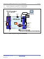
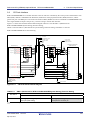
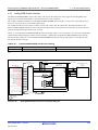
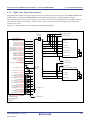
The R7S72100 includes a smaller digital data transmission system IEBus controller (EIBB) designed to execute data
transmission between units. The RTK7721000B00000BR connects the R7S72100 IEBB pin to the 4-pin 2.5mm pitch
connector via the IEBus transceiver IC.
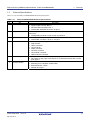
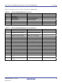
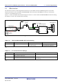
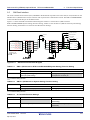
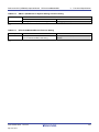
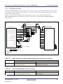
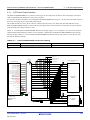
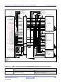
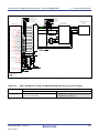
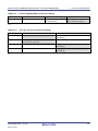
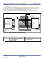
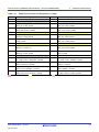
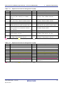
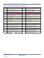
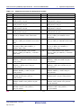
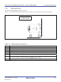
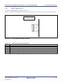
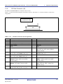
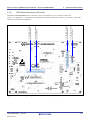
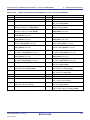
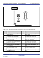
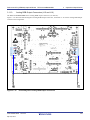
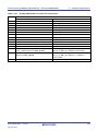
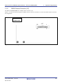
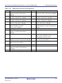
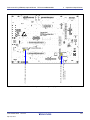
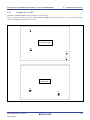
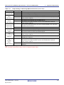
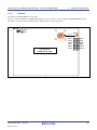
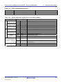
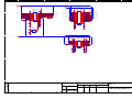
Figure 2.3.1 shows the IEBus Interface Block Diagram. Table 2.3.1 lists the RTK772100BC00000BR JP4 Function Setting,
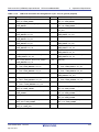
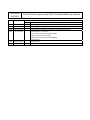
and Table2.3.2 lists the JP7 and JP2 Function Settings.
2
To CAN transceiver
Expansion
connector
2
2
IEBus transceiver
R2A11210SP (U4)
3.3V
R7S72100 (U1)
P5_10 / CTx1 / IETxD /
LCD1_DATA17
P5_9 / ET_MDC / CRx1 / IERxD /
LCD1_DATA16
2
1
3
P5_10
P5_9
P5_9
P5_10
JP7
2
1
3
JP2
IEBus connector
(J4)
5V
To LCD panel I/F2
IERxD
R
BUS+
S1
BUS-
1
2
NC
IETxD
62Ω
3
3.3V
To LAN I/F
S2
JP4
Note: Letters in Red indicate
functions in use.
nSTB
4
5V
Vcc
: Optional
Figure 2.3.1
Table 2.3.1
IEBus Interface Block Diagram
RTK772100BC00000BR JP4 Function Setting
1-2
Jumper
JP4
2-3
Use P5_9 as CRx1 input pin
None
Use P5_9 as ET_MDC output
Use P5_9 as IERxD input pin or
pin (initial setting)
LCD1_DATA16 output pin
indicates setting function.
Table2.3.2
JP7 and JP2 Function Settings
1-2
Jumper
JP7
Use P5_9 as IERxD input pin or
2-3 or Open
Use P5_9 as ET_MDC output pin (initial setting)
LCD1_DATA16 output pin
JP2
Use P5_9 as IERxD input pin
Use P5_9 as LCD1_DATA16 output pin
(initial setting)
indicates setting function.
R20UT2696EJ0005 Rev.0.05
Sep. 06, 2013
2-17