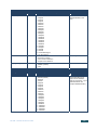
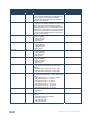
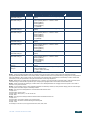
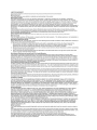
1
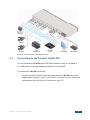
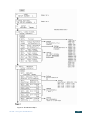
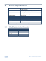
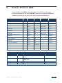
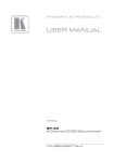
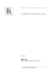
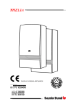
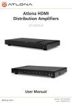
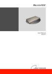
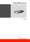
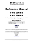
KR AMER ELECTRON ICS LT D.
USER MANUAL
MODEL:
SP-4D
4-Channel HD-SDI Synchronizer
P/N: 2900-000577 Rev 3
Contents
1 Introduction
1 2 2.1 Getting Started
Achieving the Best Performance
2 2 3 3.1 Overview
Defining the SP-4D 4-Channel HD-SDI Synchronizer
3 4 4 Installing in a Rack
7 5 5.1 Connecting the SP-4D
Connecting to the Product via RS-232
8 9 6 6.1 6.2 6.3 Operating the SP-4D
Using the LCD Display
Using the Front Panel Buttons
Using the Front Panel LEDs
10 10 11 11 7 7.1 7.2 7.3 7.4 7.5 7.6 7.7 7.8 7.9 7.10 7.11 Using the SP-4D Menus
Loading Setups
Saving Setups
Using the Factory Reset
Setting the Video Signal
Setting the Genlock
Monitoring Output
Setting the No-Signal Screen
Setting the Machine Address
Displaying Status
Setting LCD Brightness
Setting the Sleep Mode
12 15 15 15 16 18 20 21 22 22 22 23 8 8.1 Technical Specifications
Default Communication Parameters
24 24 9 Kramer Protocol 2000
25 Figures
Figure 1: SP-4D 4-Channel HD-SDI Synchronizer Front
Figure 2: SP-4D 4-Channel HD-SDI Synchronizer Rear
Figure 3: Connecting to the SP-4D Rear Panel
Figure 4: SP-4D Menu Map I
Figure 5: SP-4D Menu Map II
5 6 9 13 14 SP-4D – Contents
i
1
Introduction
Welcome to Kramer Electronics! Since 1981, Kramer Electronics has been
providing a world of unique, creative, and affordable solutions to the vast range of
problems that confront the video, audio, presentation, and broadcasting
professional on a daily basis. In recent years, we have redesigned and upgraded
most of our line, making the best even better!
Our 1,000-plus different models now appear in 11 groups that are clearly defined
by function: GROUP 1: Distribution Amplifiers; GROUP 2: Switchers and Matrix
Switchers; GROUP 3: Control Systems; GROUP 4: Format/Standards Converters;
GROUP 5: Range Extenders and Repeaters; GROUP 6: Specialty AV Products;
GROUP 7: Scan Converters and Scalers; GROUP 8: Cables and Connectors;
GROUP 9: Room Connectivity; GROUP 10: Accessories and Rack Adapters and
GROUP 11: Sierra Products.
Congratulations on purchasing your Kramer SP-4D 4-Channel HD-SDI
Synchronizer, which is ideal for the following typical applications:
•
Broadcasting studios
•
Post-production
SP-4D - Introduction
1
2
Getting Started
We recommend that you:
•
Unpack the equipment carefully and save the original box and packaging
materials for possible future shipment
•
Review the contents of this user manual
•
Use Kramer high performance high resolution cables
•
Use only the power cord that is supplied with this machine
i
2.1
Go to http://www.kramerelectronics.com to check for up-to-date
user manuals, application programs, and to check if firmware
upgrades are available (where appropriate).
Achieving the Best Performance
To achieve the best performance:
•
Use only good quality connection cables to avoid interference, deterioration
in signal quality due to poor matching, and elevated noise levels (often
associated with low quality cables)
•
Avoid interference from neighboring electrical appliances that may adversely
influence signal quality
•
Position your Kramer SP-4D away from moisture, excessive sunlight and
dust
2
SP-4D - Getting Started
3
Overview
The SP-4D 4-Channel HD-SDI Synchronizer is a synchronizer for serial digital
signals up to HD-SDI. The unit synchronizes up to four channels from the
dedicated digital genlock input or any other specified channel.
The multi-standard synchronizer SP-4D can convert the frame rate of HDTV
signals without changing the number of lines per frame or the progressive–
interlaced raster structure. It implements cross conversion between any two
standards belonging to the same group. Three groups contain mutually compatible
standards:
•
720p: 720p/50, 720p/59.95, 720p/60
•
1080i: 1080i/50, 1080i/59.95, 1080i/60, 1080psf/23.97, 1080psf/24,
1080psf/25, 1080psf/29.97, 1080psf/30
•
1080p: 1080p/23.97, 1080p/24, 1080p/25, 1080p/29.97, 1080p/30
Each of the four SDI channels contains a special audio synchronizer that deembeds all 16 input audio channels, resamples them simultaneously, and embeds
the resulting audio signals in the SDI output. This corrects signal deterioration
such as a frame drop or repetition that may occur during video signal
synchronization.
The SP-4D features:
•
Multi-standard operation: SDI (SMPTE 259M and SMPTE 344M) & HD−SDI
(SMPTE 292M)
•
Four SDI video inputs and outputs (SD, ED and all HD, besides 1080p/50
and 1080p/60) with automatic standard detection (any video input can be
used as the timing reference input for all channels instead of the dedicated
genlock input)
•
One dedicated SDI genlock input common for all four channels (also in the
same standard group)
•
An audio embedder/de-embedder that handles 16 audio channels per input
SP-4D - Overview
3
•
One VGA/UXGA port on a 15-pin HD connector (in YUV or RGBHV format
selectable from menu) to output any one of the four synchronized video
channels
•
Unbalanced stereo audio outputs on RCA connectors that can output any of
the embedded audio channels
•
A two-line, 20-character per line LCD display that shows the status of
machine while in the main mode of operation
•
Seven front panel buttons that control operation of the machine
•
Five LEDs that indicate input signal loss or genlock loss
•
One RS-232 port for controlling the SP-4D from a serial remote control
device or a PC
3.1
Defining the SP-4D 4-Channel HD-SDI Synchronizer
This section defines the SP-4D.
4
SP-4D - Overview
SP-4D – Overview
Figure 1: SP-4D 4-Channel HD-SDI Synchronizer Front
#
1
Feature
Display Panel
Function
2-line, 40-character LCD display
2
GENLOCK LED
Illuminates when a reference source is available
3
IN 1 LED
Illuminates when a valid Input 1 is connected
4
IN 2 LED
Illuminates when a valid Input 2 is connected
5
IN 3 LED
Illuminates when a valid Input 3 is connected
6
IN 4 LED
Illuminates when a valid Input 4 is connected
7
MENU Button
1. Opens the top level MENU from the MAIN mode of operation
2. Closes the top level MENU and returns to the MAIN mode of operation
3. Closes a SUBMENU and returns to the top level MENU
8
ENTER Button
1. Fixes a new value of the adjusted parameter (but doesn’t save it)
2. Opens a SUBMENU from the top level MENU item
3. Accelerates the repeat function by 16x, when this button is pressed together with LEFT or RIGHT buttons
9
◄ Left Arrow Button
Selects the previous value of a selected parameter (with repeat function)
10
▼ Down Arrow Button
Selects the next item of any menu
11
▲ Up Arrow Button
Selects the previous item of any menu
12
► Right Arrow Button
Selects the next value of selected parameter (with repeat function)
13
PANEL LOCK Button
Press for 2 seconds to enable or disable the PANEL LOCK function
5
SP-4D - Overview
5
6
Figure 2: SP-4D 4-Channel HD-SDI Synchronizer Rear
SP-4D – Overview
6
#
14
Feature
GENLOCK IN BNC Connector
Function
Connects to an SDI input, common for all four video channels. Auto standard
identification is available
15
GENLOCK OUT BNC Connector
Looping output for genlock input
16
CHANNEL 1 IN 1 BNC Connector
Connects to the channel 1 SDI source
17
CHANNEL 1 OUT 1 BNC Connector
Synchronized SDI output for channel 1
18
CHANNEL 2 IN 2 BNC Connector
Connects to the channel 2 SDI source
19
CHANNEL 2 OUT 2 BNC Connector
Synchronized SDI output for channel 2
20
CHANNEL 3 IN 3 BNC Connector
Connects to the channel 3 SDI source
21
CHANNEL 3 OUT 3 BNC Connector
Synchronized SDI output for channel 3
22
CHANNEL 4 IN 4 BNC Connector
Connects to the channel 4 SDI source
23
CHANNEL 4 OUT 4 BNC Connector
Synchronized SDI output for channel 4
24
ANALOG OUT YUV/RGB 15-pin HD Connector
Outputs the selected video channel (see Section 7.4)
25
AUDIO OUT L and R RCA Connectors
Outputs any two of the 16 audio channels per video channel
26
RS-232 9-pin D-sub Port
Connects to a PC or the remote controller via a null-modem connection
27
Power Socket
AC connector enabling power supply to the SP-4D
28
Power Switch
Illuminated switch for turning the unit ON and OFF
SP-4D - Overview
4
Installing in a Rack
SP-4D - Installing in a Rack
7
5
Connecting the SP-4D
i
Always switch off the power to each device before connecting it to your
SP-4D. After connecting your SP-4D, connect its power and then
switch on the power to each device.
To connect the SP-4D, as shown in Figure 3, do the following:
1. Connect up to four SDI input sources (for example, video cameras or a
digital video player) to the IN 1 to IN 4 BNC connectors.
2. Connect up to four SDI output acceptors (for example, a non-linear editor) to
the OUT 1 to OUT 4 BNC connectors.
3. Connect the GENLOCK IN BNC connector to an SDI genlock source (for
example an HD-SDI black-burst generator).
4. Connect the ANALOG OUT 15-pin HD connector to a computer graphics
acceptor (for example, an analog display).
5. Connect the AUDIO OUT RCA connectors to an audio acceptor (for
example, a stereo amplifier).
6. If required, connect the RS-232 9-pin D-sub connector to a controlling
computer (see Section 5.1).
8
SP-4D - Connecting the SP-4D
Figure 3: Connecting to the SP-4D Rear Panel
5.1
Connecting to the Product via RS-232
You can connect to the SP-4D via an RS-232 connection using, for example, a
PC. Note that a null-modem adapter/connection is not required.
To connect to the SP-4D via RS-232:
•
Connect the RS-232 9-pin D-sub rear panel port on the SP-4D via a 9-wire
straight cable (only pin 2 to pin 2, pin 3 to pin 3, and pin 5 to pin 5 need to be
connected) to the RS-232 9-pin D-sub port on your PC
SP-4D - Connecting the SP-4D
9
6
Operating the SP-4D
This section explains how to use the:
6.1
•
LCD display (see Section 6.1)
•
Front panel buttons (see Section 6.2)
•
LED indicators (see Section 6.3)
Using the LCD Display
The SP-4D includes a two-line, 20-character per line LCD display that displays
(while in the main mode of operation) the machine status, the genlock reference
source and standard of video signals on all four SDI outputs. The following
examples explain what is shown on the display.
1. When the genlock mode is turned OFF, the display shows:
SET3 INT.XTAL REF.
OutpForced: 720p/60
This means the setup (preset) number is 3; the internal crystal generator
XTAL is used as the genlock reference source, the standard of output signals
on all four outputs is forced to 720p/60.
2. If the genlock is turned ON and a reference input signal was selected as
dedicated input GenlockIN, the display shows:
SET3 Ref: GenlockIN
OutpForced: 720p/60
3. If the output standard selection mode is AUTO, the display shows:
SET3 Ref: GenlockIN
OutputAuto: 720p/60
4. If genlock is turned ON and SDI input channel 2 is selected as the reference
input signal, the display shows:
SET3 RefSource: IN2
OutpForced: 720p/60
10
SP-4D - Operating the SP-4D
6.2
Using the Front Panel Buttons
The front panel includes the following buttons:
MENU, ENTER, ►,▲,▼,◄. Pressing any arrow button once advances or returns
one parameter. Pressing and holding an arrow button scrolls automatically through
the menus or parameters.
Command Buttons
6.3
Button
Function
MENU
1. Opens the top level MENU from the MAIN mode of operation
2. Closes the top level MENU and returns to the MAIN mode of operation
3. Closes the SUBMENU and returns to the top level MENU
ENTER
1. Fixes a new value of the adjusted parameter (but does not save it)
2. Opens a SUBMENU from the top level MENU
3. Accelerates the repeat function by 16x, if this button is pressed together with
LEFT or RIGHT buttons
UP ▲
Selects the previous item of any menu
DOWN ▼
Selects the next item of any menu
LEFT◄
Selects the previous value of a selected parameter (with repeat function)
RIGHT ►
Selects the next value of a selected parameter (with repeat function)
PANEL LOCK
Enables or disables the PANEL LOCK function after pressing for 2sec
Using the Front Panel LEDs
Five LEDs on the front panel indicate genlock loss and the presence of a video
signal on the input of each channel.
Understanding the Front Panel LEDs
LED
Status Condition
LED Status
Genlock
Genlock turned OFF
Genlock turned ON, no appropriate reference source
Genlock turned ON, the unit is properly locked to reference
LED OFF
LED flashes
LED ON
Input 1Input 4
No video signal
Input signal standard not in same group as the output standard
Proper input signal
LED OFF
LED flashes
LED ON
SP-4D - Operating the SP-4D
11
7
Using the SP-4D Menus
This section explains how to use the various menus and their functions to operate
the SP-4D.
The menu maps in Figure 4 and Figure 5 illustrate how to navigate through the
various menus and their settings.
Note: All menus show SET1. as an example. Your setup numbers may differ.
12
SP-4D - Using the SP-4D Menus
Figure 4: SP-4D Menu Map I
SP-4D - Using the SP-4D Menus
13
Figure 5: SP-4D Menu Map II
14
SP-4D - Using the SP-4D Menus
7.1
Loading Setups
To load a saved setup:
7.2
•
Press MENU to enter the menu mode
•
Press ▼ or ▲ as needed until LOAD SETUP NUMBER is displayed
•
Press ◄ or ► to reach the setup number desired (from 1 to 16)
•
Press ENTER to load the setup
•
Press MENU to return to the normal operating mode
Saving Setups
Setups are a snapshot of all machine settings at a given instant. 16 setups are
available for saving and reloading.
Note: Most parameter changes are temporarily saved in memory only until the
SP-4D is powered OFF. To permanently save the change, perform SAVE
SETTING AS A SETUP NUMBER as shown in this procedure.
To save a setup:
•
Press MENU to enter the menu mode
•
Press ▼ or ▲ until SAVE SETTING AS SETUP NUMBER is displayed
•
Press ◄ or ► to reach the setup number desired (from 1 to 16)
If the present setup is different from the saved setup, SETUP NUMBER:
appears (with a colon)
7.3
•
Press ENTER to save the setup (the colon disappears)
•
Press MENU to return to the normal operating mode
Using the Factory Reset
Use Factory Reset to return any individual setup to its original factory setting.
To perform a factory reset:
•
Press MENU to enter the menu mode
•
Press ▼ or ▲ until SETUP 1 FACTORY RESET is displayed
SP-4D - Using the SP-4D Menus
15
7.4
•
Press ◄ or ► to reach the setup number desired (from 1 to 16)
•
Press ENTER to reset the setup
•
Save the new setup using the procedure Saving Setups in Section 7.2
•
Press MENU to return to the normal operating mode
Setting the Video Signal
Use this menu to choose between forced or auto standard identification for input
and output signals, also to select and turn ON embedded video test signals for
each channel separately.
To set the video signal:
7.4.1
•
Press MENU to enter the menu mode
•
Press ▼ or ▲ until SET1. VIDEO SIGNAL (enter submenu) is displayed
•
Press ENTER go into the submenu
•
Press ▼ and ▲ to navigate through the submenus.
Setting a Standard from the Video Signal Menu
To set a forced standard:
•
Press ▼ or ▲ until SET1. FORCED STANDARD is displayed
•
Press ◄ or ► to reach the desired settings (available settings are shown in
this table)
Video Groups
Group 1
Group 2
Group 3
720p/60 (default)
1080i/60
1080sf/30
1080p/30
525p/60
720p/59
1080i/59
1080sf/29
1080p/29
625p/50
720p/50
1080i/50
1080sf/25
1080p/25
525i/60
1080sf/24
1080p/24
625i/50
1080sf/23
1080p/23
Note: Each group contains its own mutually compatible standards.
•
Press ENTER to activate the setting (there is a 5 second delay when
changing in either direction between SD and HD settings)
16
SP-4D - Using the SP-4D Menus
7.4.2
Setting the Input Standard Mode from the Video Signal Menu
To set the input standard mode:
•
Press ▼ or ▲ until SET1. INPUT STANDARD MODE
•
Press ◄ or ► to choose settings: AUTObyChan.In or FORCED
Note: If all four SDI input settings are strictly defined and never changed,
FORCED mode is recommended.
•
7.4.3
Press ENTER to save the setting temporarily (only until powered off).
Setting the Output Standard Mode from the Video Signal Menu
To set the output standard mode:
•
Press ▼ or ▲ until SET1. OUTPUT STANDARD MODE
•
Press ◄ or ► to choose settings: AUTObyRefSour. or FORCED
Note: If all four SDI output settings are strictly defined and never changed,
FORCED mode is recommended.
•
7.4.4
Press ENTER to save the setting temporarily (only until powered off)
Running a Test Signal from the Video Signal Menu
To run a test signal:
•
Press ▼ or ▲ to choose a channel to test (1 to 4)
•
Press ◄ or ► to choose the settings: NO TEST SETTING, COLOR
BARS100%, SPLIT BARS100% or RAMP100%
•
Press ENTER to run the test
•
To stop the test, return to NO TEST SIGNAL and press ENTER
SP-4D - Using the SP-4D Menus
17
7.5
Setting the Genlock
Use this menu to set genlock parameters; activation, source and timing.
To set the genlock:
7.5.1
•
Press MENU to enter the menu mode
•
Press ▼ or ▲ until SET1. GENLOCK (enter submenu) is displayed
•
Press ENTER go into the submenu
•
Press ▼ and ▲ to navigate through the submenu
Resetting the Genlock
To reset the genlock:
•
From SET1. GENLOCK FACTORY RESET, press ENTER to reset the
genlock to its factory settings
•
7.5.2
Save the new genlock using the procedure Saving Setups in Section 7.2
Activating/Deactivating the Genlock from the Genlock Menu
When the genlock is turned OFF, an internal crystal generator is used as the
reference source and all four SDI outputs run synchronously with each other.
To activate or deactivate the genlock:
7.5.3
•
Press ▼ or ▲ until SET1. Genlock State
•
Press ◄ or ► to choose the settings: OFF(FreeRun) or ON
•
Press ENTER to save the setting temporarily (until powered down)
Setting the Genlock Reference Source from the Genlock Menu
Use the genlock reference source to select either a dedicated genlock input or any
one of the four SDI inputs.
18
SP-4D - Using the SP-4D Menus
To set the genlock reference source:
•
Press ▼ or ▲ until SET1. RefSource
•
Press ◄ or ► to choose the settings: RearPanel GENLOCK IN, SDI Ch1
(Input IN1), Ch2 ( Input IN2), Ch3 ( Input IN3) or Ch4 (Input IN4)
•
7.5.4
Press ENTER to save the setting temporarily (until powered down)
Setting the Horizontal Timing from the Genlock Menu
Use the horizontal timing to adjust the horizontal delay of an output signal relative
to the reference source signal (for each channel separately).
Possible timing values are:
•
-19600nsec to +19600nsec, step 14nsec in HDTV mode
•
-26500nsec to +26500nsec, step 19nsec in EDTV mode
•
-51800nsec to +51800nsec, step 37nsec in SDTV mode
Default timing is 0nsec. Negative values advance the output signal, positive values
retard the signal.
To speed up the adjustment, press and hold the appropriate ◄ or ► button
(repeat mode). For the16x ultra repeat mode, press and hold the appropriate
◄ or ► button while pressing the ENTER button. In this case, the adjusted
parameter changes by steps of 16 units.
To quickly reset to the factory default value, press and hold both ◄ and ► buttons
together for 1 sec.
To set the horizontal timing:
•
Press ▼ or ▲ until SET1. SDI Ch1 TIMING HORIZONTAL, press ► to
advance the timing by 14ns and ◄ to retard the timing by 14ns
•
Press ENTER to save the setting temporarily (until powered down)
•
Repeat for channels 2 through 4
•
Save the new horizontal timing using the procedure Saving Setups in
Section 7.2
SP-4D - Using the SP-4D Menus
19
7.6
Monitoring Output
Use output monitoring to select any one of 4 SDI channel (video and embedded
audio) for monitoring purposes.
To set output monitoring:
•
Press MENU to enter the menu mode
•
Press ▼ or ▲ until SET1. MONITORING OUTP. (enter submenu)
is displayed
7.6.1
•
Press ENTER go into the submenu
•
Press ▼ and ▲ to navigate through the submenu
Selecting the Output Monitoring Channel from the Output
Monitoring Menu
To select an output monitoring channel:
•
Press ▼ or ▲ until SET1. Video & Audio Monitoring
•
Press ◄ or ► to choose the settings: SDI CH1, SDI CH2, SDI CH3, SDI
CH4
•
7.6.2
Press ENTER to save the setting temporarily (until powered down)
Selecting the Video Output Format from the Output Monitoring
Menu
To select a video output format:
7.6.3
•
Press ▼ or ▲ until SET1. Analog Video Output Format
•
Press ◄ or ► to choose the settings: RGBHV and YUV
•
Press ENTER to save the setting temporarily (until powered down)
Selecting the Audio Output Group from the Output Monitoring
Menu
The audio output group selects the embedded audio group – two stereo audio
channels that can be extracted from the selected SDI channel. After digital to
analog conversion the audio is available on both RCA output connectors.
20
SP-4D - Using the SP-4D Menus
To select an audio output group:
•
Press ▼ or ▲ until SET1. AUDIO Outputs Channels
•
Press ◄ or ► to choose the settings:
Channels 1+2
Group1
Channels 3+4
Group1
Channels 5+6
Group2
Channels 7+8
Group2
Channels 9+10
Group3
Channels 11+12
Group3
Channels 13+14
Group4
Channels 15+16
Group4
•
Press ENTER to save the setting temporarily (until powered down)
•
Press MENU to return to the top level menu
•
Save the new audio group setting by using the Saving Setups procedure in
Section 7.2
7.7
Setting the No-Signal Screen
The no-signal screen appears in the absence of an input signal or when input and
output signals are incompatible.
To set the no-signal screen:
•
Press MENU to enter the menu mode
•
Press ▼ or ▲ until NoSignal Screen is displayed
•
Press ◄ or ► to choose the settings: BLUE SCREEN, BLACK SCREEN or
NoColorInsert (default)
•
Press ENTER to save the setting
Note: This assignment affects all 16 setups (presets) after ENTER is pressed. The
setting is saved with auto power-down.
SP-4D - Using the SP-4D Menus
21
7.8
Setting the Machine Address
To set the machine address:
•
Press MENU to enter the menu mode
•
Press ▼ or ▲ until Address of machine is displayed
•
Press ◄ or ► to choose the settings: 0x18 (default), 0x19
•
Press ENTER to save the setting
Note: This assignment affects all 16 setups (presets) after ENTER is pressed. The
setting is saved with auto power-down.
7.9
Displaying Status
The next six top-level menu items give a read-only display of all four SDI inputs,
the genlock input status and the reference lock status.
To display a status:
•
Press MENU to enter the menu mode
•
Press ▼ or ▲ until the status of the desired SDI channel, SDI genlock input
or reference lock is displayed
7.10
Setting LCD Brightness
This setting adjusts the brightness of the LCD display.
To set LCD brightness:
•
Press MENU to enter the menu mode
•
Press ▼ or ▲ until LCD active operating brightness is displayed
•
Press ◄ or ► to change the settings from 0% to 100% (95% default)
Note: This assignment affects all 16 setups (presets) after ENTER is pressed.
The setting is saved with auto power-down.
22
SP-4D - Using the SP-4D Menus
7.11
Setting the Sleep Mode
This setting adjusts the sleep mode brightness of the LCD display.
To set the sleep mode brightness of the LCD:
•
Press MENU to enter the menu mode
•
Press ▼ or ▲ until LCD sleep mode brightness is displayed
•
Press ◄ or ► to change the settings from 0% to 100% (50% default)
Note: This assignment affects all 16 setups (presets) after ENTER is pressed. The
setting is saved with auto power-down.
SP-4D - Using the SP-4D Menus
23
8
Technical Specifications
INPUTS:
4 SDI/HD-SDI, 1 SDI/HD-SDI genlock (digital signal) 75Ω
on BNC connectors
OUTPUTS:
4 SDI/HD−SDI, 1 genlock 75Ω on BNC connectors, 1
VGA/UXGA port on a 15−pin HD connector (YUV/RGB
selectable); stereo audio on 2 RCA connectors
CONTROLS:
7 front panel buttons, RS-232
INDICATORS:
LCD display, 5 input and genlock LEDs
POWER SOURCE:
220V AC, 27VA
OPERATING TEMPERATURE:
0° to +55°C (32° to 131°F)
STORAGE TEMPERATURE:
-45° to +72°C (-49° to 162°F)
HUMIDITY:
10% to 90%, RHL non-condensing
DIMENSIONS:
19" x 7" x 1U W, D, H
WEIGHT:
1.81kg (4.0lbs)
ACCESSORIES:
Power cord, Windows®-based control software, rack “ears”
Specifications are subject to change without notice at http://www.kramerelectronics.com
8.1
Default Communication Parameters
Protocol 2000
RS-232
24
Baud Rate:
9600
Data Bits:
8
Stop Bits:
1
Parity:
None
Command Format:
HEX
SP-4D - Technical Specifications
9
Kramer Protocol 2000
Protocol 2000 for the SP-4D is described below. For RS-232 a null-modem
connection between the PC and the SP-4D is required, and data is at 9600 baud,
no parity, 8 data bits, and 1 stop bit. All values shown are hexadecimal.
INSTRUCTION
1st Byte
2nd Byte
3rd Byte
4th Byte
COMMENT
RESET
REPLY TO RESET
GENLOCK RESET
REPLY TO GENLOCK RESET
00
40
11
51
80
80
80
80
80
80
80
80
98+Machine Addr
98+Machine Addr
98+Machine Addr
98+Machine Addr
Power up, pseudo
80+Parameter
Number
80+Parameter
Number
80+Parameter
Number
80+Parameter
Number
80+Parameter
Number
80
B8+40*MSB_data+
Machine Addr
B8+40*MSB_data+
Machine Addr
READ TWO-BYTE LOCAL PARAMETER 20
REPLY TO READ TWO-BYTE LOCAL
PARAMETER
60
WRITE TWO-BYTE LOCAL
PARAMETER
21
REPLY TO WRITE TWO-BYTE LOCAL
PARAMETER
61
READ GLOBAL / ONE-BYTE LOCAL
PARAMETER
20
REPLY TO READ GLOBAL / ONE-BYTE
LOCAL PARAMETER
60
80+Parameter
Number
WRITE GLOBAL / ONE-BYTE LOCAL
PARAMETER
21
80+Parameter
Number
REPLY TO WRITE GLOBAL / ONEBYTE LOCAL PARAMETER
61
80+Parameter
Number
SAVE
23
IDENTIFY MACHINE
IDENTIFY FIRMWARE VERS.
80+Parameter
Data
80+Parameter
Data
80+Parameter
Data
80
Timing and phase
See TABLE 3 and
Notes 1, 2
See TABLE 3 and
Notes 1, 2
B8+40*MSB_data+ See TABLE 3 and
Machine Addr
Notes 1, 2
B8+40*MSB_data+ See TABLE 3 and
Machine Addr
Notes 1, 2, 3
98+Machine Addr
See TABLE 1, 2
and Note 1
98+Machine Addr
See TABLE 1, 2
and Note 1
98+Machine Addr
See TABLE 1, 2
and Note 1
80 + Initial Setup
Number
80+Parameter
Data
80+Parameter
Data
80+Parameter
Data
80+Destination
Setup Number
3D
81
3D
83
98+Machine Addr
See TABLE 1, 2
and Note 1, 3
98+Machine Addr
See NOTE 4
80
98+Machine Addr
See NOTE 5
80
98+Machine Addr
See NOTE 6
TABLE 1
Global Parameters for Supported Commands (Values in hexadecimal)
Parameter
Number
Data
Panel Lock
0
0 – Off (default)
1 – On
No_Signal_Color
1
0 – No_Color_Insert (default)
1 – Black screen
2 – Blue screen
PC Addr
2
0, 1 (corresponds to 0x18 and 0x19)
Setup Number
3
0 – F (0 corresponds to setup#1, F to setup#16)
The next addresses allow periodic request and read of the machine status (read only):
SP-4D - Kramer Protocol 2000
Comments
Read only
25
TABLE 1
Global Parameters for Supported Commands (Values in hexadecimal)
Parameter
Number
Data
Ch1 Input Standard
9
0 – 15
0 – 720p/60
1 – 720p/59
2 – 720p/50
3 – 1080i/60
4 – 1080i/59
5 – 1080i/50
6 – 1080p/30
7 – 1080p/29
8 – 1080p/25
9 – 1080p/24
A – 1080p/23
B – 1080sf/30
C – 1080sf/29
D – 1080sf/25
E – 1080sf/24
F – 1080sf/23
10 – 525p/60
11 – 625p/50
12 – 525i/60
13 – 625i/50
14 – Unidentified signal
15 – No input signal
Ch2 Input Standard
A
0 – 15
Ch3 Input Standard
B
0 – 15
Ch4 Input Standard
C
0 – 15
Actual Output Standard
D
0 – 13
0 – 720p/60
1 – 720p/59
2 – 720p/50
3 – 1080i/60
4 – 1080i/59
5 – 1080i/50
6 – 1080p/30
7 – 1080p/29
8 – 1080p/25
9 – 1080p/24
A – 1080p/23
B – 1080sf/30
C – 1080sf/29
D – 1080sf/25
E – 1080sf/24
F – 1080sf/23
10 – 525p/60
11 – 625p/50
12 – 525i/60
13 – 625i/50
26
Comments
Status of standard
autoidentification, read
only.
The coding differs from
parameter 40 (forced
standard)
Values and standards
same as above (read only)
Values and standards
same as above (read only)
Values and standards
same as above (read only)
Common to all 4 channels,
read only
SP-4D - Kramer Protocol 2000
TABLE 1
Global Parameters for Supported Commands (Values in hexadecimal)
Parameter
Number
Data
Genlock Input Standard
E
0 – 15
0 – 720p/60
1 – 720p/59
2 – 720p/50
3 – 1080i/60
4 – 1080i/59
5 – 1080i/50
6 – 1080p/30
7 – 1080p/29
8 – 1080p/25
9 – 1080p/24
A – 1080p/23
B – 1080sf/30
C – 1080sf/29
D – 1080sf/25
E – 1080sf/24
F – 1080sf/23
10 – 525p/60
11 – 625p/50
12 – 525i/60
13 – 625i/50
14 – Unidentified signal
15 – No input signal
Genlock Status
F
0–2
0 – No reference signal
1 – Loss of lock to reference
2 – Proper lock to reference
Output_Video_Format
12
0–1
0 – RGBHV (default)
1 – YUV
Comments
Status of standard
autoidentification, read
only.
Read only
Read and write allowed
TABLE 2
One-Byte Local Parameters (Values in hexadecimal)
Parameter
Number
Data
Forced Standard
40
0 – 13
0 – 480i/60 (default)
1 – 480p/60
2 – 576i/50
3 – 576p/50
4 – 720p/50
5 – 720p/59
6 – 720p/60
7 – 1080i/50
8 – 1080i/59
9 – 1080i/60
A – 1080p/23
B – 1080p/24
C – 1080p/25
D – 1080p/29
E – 1080p/30
F – 1080sf/23
10 – 1080sf/24
11 – 1080sf/25
12 – 1080sf/29
13 – 1080sf/30
SP-4D - Kramer Protocol 2000
Comments
(May be used as input
forced standard and as
output forced standard.
See two next items – "Input
Standard Mode" and
"Output Standard Mode")
27
TABLE 2
One-Byte Local Parameters (Values in hexadecimal)
Parameter
Number
Data
Input Standard Mode
41
0–1
0 – Auto identified standard using appropriate input
signal (on each channel separately) (default)
1 – Forced input standard defined in previous item
(common to all 4 channel)
Output Standard Mode
42
0–1
0 – (Default) auto identified standard, based on signal
that has been preselected as reference genlock
source. (This source can be selected between either
dedicated genlock input or any 4 channel input, see
parameter 4B – genlock reference source). If genlock
is turned off, forced standard is used instead of auto.
1 – Forced output standard defined in parameter 40
(common to all 4 channels).
Test_Ch1
43
0–3
0 – Test off (default)
1 – Color bars 100%
2 – Split bars 100%
3 – Ramp 100%
Test_Ch2
44
0–3
0 – Test off (default)
1 – Color bars 100%
2 – Split bars 100%
3 – Ramp 100%
Test_Ch3
45
0–3
0 – Test off (default)
1 – Color bars 100%
2 – Split bars 100%
3 – Ramp 100%
Test_Ch4
46
0–3
0 – Test off (default)
1 – Color bars 100%
2 – Split bars 100%
3 – Ramp 100%
Video_Monitor
47
0–3
0 – SDI channel1 is selected for monitor output
(default)
1 – SDI channel2 is selected for monitor output
2 – SDI channel3 is selected for monitor output
3 – SDI channel4 is selected for monitor output
Audio_Monitor
48
0 – 7 defines 2 of 16 SDI audio channel to extract
from selected (in previous item – Video_Monitor) SDI
channel
0 – SDI audio channels 1 + 2 group 1 (default)
1 – SDI audio channels 3 + 4 group 1
2 – SDI audio channels 5 + 6 group 2
3 – SDI audio channels 7 + 8 group 2
4 – SDI audio channels 9 + 10 group 3
5 – SDI audio channels 11 + 12 group 3
6 – SDI audio channels 13 + 14 group 4
7 – SDI audio channels 15 + 16 group 4
Genlock Off/On
4A
0–1
0 – off (default)
1 – on
Genlock_Ref_Source
4B
0 – 4 defines video input that will be used as genlock
reference
0 – dedicated genlock input (default)
1 – SDI channel1 input
2 – SDI channel2 input
3 – SDI channel3 input
4 – SDI channel4 input
28
Comments
SP-4D - Kramer Protocol 2000
TABLE 3
Two-Byte Local Parameters (Values in hexadecimal)
Parameter
Number
Data (LB=low byte, HB=high byte)
Comments
Low Byte of Channel 1
4C
LB = H % 256 i.e. Remainder on dividing H by 256
Horizontal Timing H
(signed)
High Byte of Channel 1
4D
HB = Floor(H/256) i.e. Greatest signed integer less or
Horizontal Timing H
equal to (H/256) where H = -1400 to +1400
14ns step (HDTV)
18ns step (EDTV)
37ns step (SDTV)
H = 0 (default)
Low Byte of Channel 2
4E
LB = H % 256 i.e. Remainder on dividing H by 256
Horizontal Timing H
(signed)
High Byte of Channel 2
4F
HB = Floor (H/256) i.e. Greatest signed integer less or
Horizontal Timing H
equal to (H/256) where H = -1400 to +1400
14ns step (HDTV)
18ns step (EDTV)
37ns step (SDTV)
H = 0 (default)
Low Byte of Channel 3
50
LB = h % 256 i.e. Remainder on dividing H by 256
Horizontal Timing H
(signed)
High Byte of Channel 3
51
HB = Floor (H/256) i.e. Greatest signed integer less or
Horizontal Timing H
equal to (H/256) where H = -1400 to +1400
14ns step (HDTV)
18ns step (EDTV)
37ns step (SDTV)
H = 0 (default)
Low Byte of Channel 4
52
LB = h % 256 i.e. Remainder on dividing H by 256
Horizontal Timing H
(signed)
High Byte of Channel 4
53
HB = Floor (H/256) i.e. Greatest signed integer less or
Horizontal Timing H
equal to (H/256) where H = -1400 to +1400
14ns step (HDTV)
18ns step (EDTV)
37ns step (SDTV)
H = 0 (default)
Low Byte of Vertical
54
LB = V % 256 i.e. Remainder on dividing V by 256
Timing V
(signed)
High Byte of Vertical
55
HB = Floor (V/256) i.e. Greatest signed integer less or
Timing V
equal to (V/256) where
V = -625 to +625 1 line step
V = 0 (default)
NOTE 1: There are global parameters that are invariable in the case of a setup number change, and local parameters that have
appropriate parameter data values for each setup number (16 different values, stored in special memory). During write or read operations
with local parameters, the PC gets access only to the active local parameter that corresponds to an actual setup number. Certain local
parameters (not all) are represented in two-byte format because of their large adjustment.
NOTE 2: While writing or reading two-byte parameters (PC -> machine), you must send two consecutive write or read commands (each
command having a conventional 4-byte structure) for low (first) and high bytes with a minimal time interval between them.
NOTE 3: These commands are sending by unit also when Local / Global parameters are changing via the front panel or as a result of
execution of any other command.
NOTE 4: If it is necessary merely to save adjusted parameters in initial setup number (no setup number change), then the value of byte3
must be equal to the value of byte2 - initial setup number.
NOTE 5: The reply to the Identify Machine command shows the machine name
1st byte: 0x7d
2nd byte: 0x80 + 0x00 (0 dec)
3rd byte: 0x80 + 0x04 (4 dec) - for the unit SP-4D
4th byte: 0x98
NOTE 6: The reply to the Identify Firmware command shows the firmware version as
1st byte: 0x7d
2nd byte: 0x80 + the version number prior to decimal point
3rd byte: 0x80 + the version number following the decimal point
4th byte: 0x98
For example, for version 3.5, the reply would be 0x7d, 0x83, 0x85, 0x98.
SP-4D - Kramer Protocol 2000
29
For the latest information on our products and a list of Kramer distributors,
visit our Web site where updates to this user manual may be found.
We welcome your questions, comments, and feedback.
Web site: www.kramerelectronics.com
E-mail: [email protected]
!
SAFETY WARNING
Disconnect the unit from the power
supply before opening and servicing