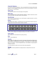
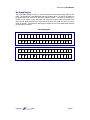
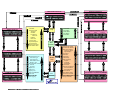
1
Autosearch II User Manual
CONTENTS
OVERVIEW .............................................................................................................................................. 4
CONTROL PANEL .................................................................................................................................. 5
INITIAL START UP ................................................................................................................................. 7
BAR GRAPH DISPLAY ................................................................................................................................. 8
SYSTEM SOFTWARE ............................................................................................................................ 9
PRODUCT SETUP MENU .................................................................................................................... 10
THRESHOLD .............................................................................................................................................. 10
DETECTION MODE ................................................................................................................................... 10
GAIN .......................................................................................................................................................... 10
REJECT DELAY .......................................................................................................................................... 10
REJECT DURATION ................................................................................................................................... 10
REJECT CHECK ........................................................................................................................................ 10
PRINT PRODUCT ....................................................................................................................................... 10
LOAD MENU ............................................................................................................................................. 10
SAVE MENU ............................................................................................................................................... 10
DELETE MENU .......................................................................................................................................... 10
FREE MENUS ............................................................................................................................................. 10
PRINT MENUS ........................................................................................................................................... 10
MACHINE SETTING MENU ............................................................................................................... 11
GRAVITY FEED ......................................................................................................................................... 11
IMPERIAL ON/OFF .................................................................................................................................... 11
TACHO ON/OFF ........................................................................................................................................ 11
LINE SPEED ............................................................................................................................................... 11
HEAD SIZE ................................................................................................................................................. 11
RBS DELAY ............................................................................................................................................... 12
SELECT LANGUAGE .................................................................................................................................. 12
UNIT NUMBER ........................................................................................................................................... 12
NETWORK ................................................................................................................................................. 12
PRINTER BAUD .......................................................................................................................................... 12
PRINTER SETUP......................................................................................................................................... 12
ENG PASSWORD ........................................................................................................................................ 12
USER PASSWORD ...................................................................................................................................... 12
SETUP CODES ............................................................................................................................................ 12
TEST FUNCTIONS ................................................................................................................................ 13
METAL TEST.............................................................................................................................................. 13
SET DATE .................................................................................................................................................. 13
REJECT TEST ............................................................................................................................................. 13
ALARM TEST ............................................................................................................................................. 13
DISPLAY TEST ........................................................................................................................................... 13
OVERRIDE ................................................................................................................................................. 13
LAST FAULT .............................................................................................................................................. 13
PRINT PEAK DATA .................................................................................................................................... 13
TEST LOGGING ......................................................................................................................................... 13
Copyright
1998
Page 1
Autosearch II User Manual
SETTING UP THE METAL DETECTOR.......................................................................................... 14
LEARNING PRODUCT ................................................................................................................................ 14
THRESHOLD ............................................................................................................................................... 14
SET PRE AMP GAIN ................................................................................................................................... 15
SET REJECT TIMING AUTOMATIC REJECT SYSTEM .............................................................................. 15
THE MENU SYSTEM............................................................................................................................ 16
TO SAVE A MENU ..................................................................................................................................... 16
TO LOAD A MENU .................................................................................................................................... 16
TROUBLE SHOOTING......................................................................................................................... 17
SPECIFICATION ................................................................................................................................... 18
C E COMPLIANCE ................................................................................................................................ 20
INFRARED REMOTE CONTROL - APPENDIX 1 .............................................................................. 22
SET UP CODES - APPENDIX 2 ............................................................................................................... 26
PRODUCT MENU LIST - APPENDIX 3 ................................................................................................ 27
ECLECTRICAL TERMINATION - APPENDIX 4................................................................................ 28
Copyright
1998
Page 2
Autosearch II User Manual
ELECTRICAL SAFETY NOTICE
Only qualified personnel should remove the front panel by undoing
the centre screw.
Opening this panel exposes high voltage terminals.
COMPLIANCE NOTICE
The equipment has been designed to be part of an “INSTALLATION” as defined by the current
European Directives. The operation of any reject mechanism controlled by this equipment may
be hazardous; it may operate without warning. Its design & implementation must be carried
out by competent personnel in accordance with local health & safety regulations and
appropriate “installation” documentation maintained. It contains hazardous voltages which
must be treated in accordance with this handbook.
Note: “CINTEX Limited” is referred to several times in this handbook.
This should be taken to include this company’s associate companies & agents.
CINTEX Limited
Featherstone Road
Wolverton Mill
Milton Keynes
Bucks MK12 5QN
England
Tel No: +44 (0) 1908 629200
Fax No: +44 (0) 1908 579824
Email: [email protected]
Copyright
1998
Page 3
Autosearch II User Manual
Overview
CINTEX Autosearch metal detectors are designed to detect metal contaminants in a wide range
of products. A high frequency magnetic field is set up inside the detector. Ferrous or nonferrous particles cause minute disturbances of the field. These disturbances are picked up by
search coils, amplified and used to trip alarm circuits or trigger the automatic rejection of the
contaminated product. The coils are cast into an epoxy resin block to ensure the utmost
stability and freedom from the effects of water or vibration.
In most instances, the product being checked also causes disturbances in the magnetic field.
Unfortunately these disturbances are usually very much larger than those from small metal
particles. However, field disturbances have tow fundamental parameters - “magnitude” and
“phase”. A microprocessor continuously examines these two parameters and learns the signals
from “clean” products. It keeps a running average and uses the information to disregard
signals arising from them whilst still being sensitive to signals from metal particles as these are
of different phases. The microprocessor uses sophisticated filtering techniques to further
enhance the metal detection capability.
The sensitivity that can be achieved depends on the size of signal from the product and any
variability in its phase. Clearly, for a consistent product, a tiny disturbance will stand out as
being due to a metal contaminant, leading to high sensitivity. If the phase varies from one
product item to the next, a much larger contribution from a metal contaminant is needed
before the combined signal will stand out as being significantly different from the norm to be
rejected as contaminated. The sensitivity will therefore be reduced. A pied would be a good
example of a variable product. Each ingredient - the crust, the jelly and the filling will
contribute a different phase. The metal detector can only sense the combined phase. If the
proportions of such ingredients vary, the overall signal will vary, leading to lower sensitivity. It
is therefore difficult to predict usable sensitivity - even if several samples are tried out. Only
when the detector is sampling products under actual production conditions can sensibility be
determined reliably.
When a contaminant is detected, the microprocessor tracks the contaminated item as it moves
out of the detector head towards the rejection device and operates the reject device at the
right time. The microprocessor also carries out “housekeeping” tasks such as monitoring all
key areas of the detector and reject device, and warning of a malfunction, running the alphanumeric display and, if required, reporting detection activity to a central computer.
Copyright
1998
Page 4
Autosearch II User Manual
Control Panel
Indicator Lamps
Power On
Override
Metal
Alpha-Numeric Display
Green
Amber
Red
Special Function Keys
Reset
Reject
Count
Mains
Fuse
Power
Switch
Alarm
Override
Numeric Keypad
Numeric Keypad
Copyright
1998
Page 5
Autosearch II User Manual
Controls & Indicators
Fig 1 shows the controls and indicators. These are accessible after the access panel has been
removed. To do this, engage the special key and turn half a turn anti clockwise to free the 4
special fasteners. Lift off the panel.
Power Lamp
This indicates the presence of the mains supply to the equipment.
Metal Lamp
This is lit momentarily when a metal contaminant is detected. It flashes continuously if a fault
has been discovered in the detector head or reject mechanism.
Override Lamp
This is lit when the override switch is set so that all product is passed unchecked i.e. with the
detector reject inoperative. See on.
Display
This is a multi purpose display. In standard mode, the top part shows the detector output as a
bar graph with the lower part showing the detection threshold.
ζ
3
0
Ï
T
H
R
E
S
H
O
L
D
A variety of other messages can be displayed according to the condition of the machine.
Power Switch
This is normally left on and switched off only during servicing.
Fuse
20mm 1.0amp SB glass fuse
Override
In the override “ON” position (up), the circuits to the reject system or alarm are held in the “no
metal” condition. This allows the line to be run in the event of a failure in the metal detector.
It is also useful for the initial setting up of the detector. In this position, the “override” warning
lamp is lit (see above). It must be emphasised that, in this condition, the reject system is
completely inoperative.
For normal operation the switch must be down and the lamp extinguished.
Keypad
This is used to select the parameters for display and also to modify and then store them.
See on.
Copyright
1998
Page 6
Autosearch II User Manual
INITIAL START UP
Switch On
Switch the power on and the alarm switch to ‘override’. Turn on the supply to the head. The
green and amber lamps should be lit. Check the reject mechanism is in the non-reject position
and any alarms are not activated. The display should indicate:
‘Initialising 2’
The ‘Initialising’ display will count down to 1 then the computer will check the head balance.
The display will count down from 25 until the balance is determined to be OK while the display
indicates:
‘Re-balancing head 8’
If the head balance is OK the display will switch to the bar graph display, which is the normal
operating mode. The display will indicate:
‘bar graph display’
‘30 Ï THRESHOLD’
The bar graph display represents the signal level currently directed with the arrow indicating
where the value of the threshold (30 in this example) is positioned. The bar graph should
display a level less than the threshold and the red metal light should not be lit.
If the machine does not come up, turn the mains switch off and then on again.
If it still fails to come up then contact CINTEX.
OFFER A LARGE METAL OBJECT, SUCH AS A SCREWDRIVER TO THE APERTURE. THE SIGNAL
SHOULD GO TO MORE THAN 1000.
The bar graph will go all the way to the right and the bottom line of the display will change to
indicate:
‘bar graph display’
‘30 ^ METAL 14121’
The red light should be lit.
Copyright
1998
Page 7
Autosearch II User Manual
Bar Graph Display
This is the default display on start up. It can be accessed any time by pressing [CODE] up to 3
times. The bottom line of the display will show the threshold value. The top line of display is a
bar graph that moves from left to right as the signal increases. The arrow on bottom line is
pointing to the position on the bar graph that represents a signal equal to threshold value.
When the bar graph extends to the right beyond the arrow the metal will come on and the
reject will operate. The bottom line will change to display the size of the metal signal whenever
the threshold is exceeded.
Bar Graph Display
ζ
ζ
Copyright
3
0
ζ
ζ
3
0
Ï
ζ
ζ
ζ
Ï
1998
ζ
ζ
T
H
R
E
S
H
ζ
ζ
ζ
ζ
ζ
ζ
M
E
T
A
L
O
L
D
6
3
Page 8
Autosearch II User Manual
SYSTEM SOFTWARE
This section describes the Autosearch II system software. The software uses a simple menu
structure to prompt the user the values for all system parameters.
Main Menu
Pressing [SET] at the Bar Graph Display will bring up the Main Menu.
The Main Menu has four items that can be selected:
Pressing [ENTER] will scroll forward through the four items;
1) Product Settings
2) Menu Functions
3) Machine Settings
4) Test Functions
Pressing [CLEAR] will scroll backward through the four items.
Pressing [CODE] will return you the Bar Graph Display.
Pressing [SET] will bring up the sub menu for the item currently displayed.
The Product settings sub menu will prompt you for the values to all parameters that change
with a product. The Machine Settings sub menu will prompt you for values for all parameters
that are specific to a particular detector head system, these setting should not change once set.
The Menu Functions sub menu will allow you to store and retrieve up to 50 sets of product
parameters. The Test Functions sub menu allows you to test the operation of the alarm and
reject mechanisms as well as test the detection capability of the system. Following is detailed
description of each of the items in the four sub menus:
Copyright
1998
Page 9
Autosearch II User Manual
PRODUCT SETUP MENU
Threshold
This will set the value above which the SIGNAL will cause a reject. Normally set to a value 50%
higher than the highest signal obtained from just the product.
Detection Mode
Normally the STANDARD mode is used.
Other options are:
FIXED PHASE
DIFFICULT
AUTOLEARN
DUAL PRODUCT
Gain
Normally set to 4, this may have to be lowered if the product generates a very strong signal.
Reject Delay
This value sets the time delay before actuating the reject mechanism. If a tacho is being used
then you will have to enter the actual distance from the centre of the metal detector to the
centre of the reject. Make fine adjustments to this value so that metal contaminated product is
rejected every time. Test with the metal in both leading and trailing positions on the product.
Reject Duration
This value sets the duration of the reject actuation. Normally set to value small enough to
ensure rejection of just the contaminated product.
Reject Check
This value sets a time limit for confirming the rejection. A proximity switch or photo eye can be
used to detect the contaminated product as it falls from the line. If the eye does not detect it
within the confirm time then is assumed that a known contaminated product was not rejected
and the fault relay contact will change state, allowing for an alarm etc.
Print Product
Pressing [SET] will generate a printout of all the parameters in the Product Menu.
Load Menu
Enter the menu/number/name and the previously stored Product Set-up parameters will be
loaded into the computer.
Save Menu
Enter a number/name and the current Product Set-up parameters will be stored in battery
backed memory. These parameters can be recalled anytime by using the Load Menu function
above.
Delete Menu
Enter the name of a menu to remove from the battery backed up ram.
Free Menus
This option will display the total number of menus used and the number of menus available.
Print Menus
Enter the name of a menu and all parameters stored for that menu will be printed. Menu
names can only be entered with the remote control option - See Appendix 1.
Copyright
1998
Page 10
Autosearch II User Manual
MACHINES SETTINGS MENU
Maintenance Mode
Operational when detector connected to MIACS
Gravity Feed
Set this to ON if the speed of the product is not easily measured (as in the case with pipelines)
or if the product is indeed falling under gravity. For most conveyed products this will be set of
OFF and the actual belt speed will be entered at the BELT SPEED menu item.
Imperial On/Off
Set this ON to read speeds in feet per minute or OFF to read speeds in meters per minute.
Tacho On/Off
If a tacho is installed to measure the speed of the product then this should be turned ON and a
value for the tacho calibration factor should be entered.
Line Speed
Fixed speed conveyors should have the belt speed entered here. It is important that this speed
is set correctly.
Head Size
This tells the computer what size the aperture is on the metal detector.
Enter a value based on the aperture height from the chart below:
Aperture
Height (inches)
Copyright
Setting
Value (mm)
1”
(pharmaceutical)
110
2”
(pharmaceutical)
200
3”
(pharmaceutical)
280
2”
(pipeline)
150
3”
(pipeline)
220
4”
(standard)
250
5”
(standard)
380
6”
(standard)
400
7”
(standard)
450
8”
(standard)
500
10” (standard)
600
12” & larger
800
1998
Page 11
Autosearch II User Manual
Ferrite Null
Displays the setting of the factory test phase.
RBS Delay
When using a ring bell and stop system, this value can be used to automatically restart the belt
after a time-out period. If the time-out period is set to zero, the belt will not start until the
[DISPLAY] or [CODE] keys are pressed.
Select Language
English is the default language with Dutch also available French and Spanish languages will be
available soon.
Unit Number
This is simply an ID number so that you can identify this machine form a remote PC. This
number also appears on printouts, allowing you to identify which machine the report came
from. It is suggested that you set this number equal to the number of the production line it is
installed on (i.e. UNIT 3 on line 3).
Network
Switch to ON if MIACS the Management Information And Control System software has been
installed on a PC with network cables daisy chained to the AUTOSEARCH units. When turned
on you will be prompted to give the unit a unique network address so that MIACS can identify
it. You will also have to select a baud rate for communications, 9600 baud is recommended.
If MIACS is not going to be used leave this turned OFF.
Printer Baud
Select a baud rate for your serial printer. Normally 9600 is used but some printers can only
handle 2400. Check your printer manual to find out if it can handle 9600.
Printer Set-up
Pressing [SET] will generate a printout of all the machine settings in this menu.
The output is not buffered, so if a printer is not hooked up the data is lost.
Eng Password
This password (actually a number 1-32000) restricts access to the Machine Menu.
The parameters can be viewed but nothing can be changed without first knowing the
password. Setting the password to zero turns off the password protection.
User Password
This password (actually a number 1-32000) restricts access to the Product, Menu & Test
Menus. The parameters can be viewed but nothing can be changed without first knowing the
password. Setting the password to zero turns off the password protection.
Set-up Codes
This option allows you to access any of the parameters and settings etc., directly without
scrolling through menus. It is intended primarily for use with the hand held remote controller
and maintains compatibility with Autosearch I. See appendix 2 for a complete list of codes and
a description of how to use them.
Copyright
1998
Page 12
Autosearch II User Manual
TEST FUNCTIONS
Metal Test
This function allows you to enter the size and type of metal sample used for testing and then
records whether or not it was detected. This is useful for printed reports as it distinguishes
between QC testing of the machine and actual metal contamination.
Set Date
Allows you to set the correct date and time. Use the [SET] key to enter the dash (-) between
days & months & years and hours & mins & secs.
Reject Test
Pressing [SET] will simulate a metal signal, causing the reject to operate. The reject count is
not affected by this.
Alarm Test
Pressing [SET] will simulate a fault signal, causing the fault alarm to activate.
Display Test
This function rests the display by illuminating all segments.
Override
This function toggles the metal reject between active and non-active.
Last Fault
Displays the last fault or error message.
Print Peak Data
For CINTEX engineering use only.
Test Logging
For CINTEX engineering use only.
Copyright
1998
Page 13
Autosearch II User Manual
SETTING UP THE METAL DETECTOR
This section will describe the basic procedure for setting up a CINTEX Autosearch II metal
detector installed on a system.
The machine set-up parameters would have been factory set and will not need changing. If
only a detector head has been supplied to be fitted onto a system please refer to the SYSTEM
INSTALLATION MANUAL.
First the product is learnt and the PRODUCT MENU is completed telling the software all about
the product. Then the MENU FUNCTIONS are used to store the product parameters for easy
loading next time. These procedures are explained in detail here.
Learning Product
It is important that product is used taken directly from the production line NOT PRODUCT
THAT HAS BEEN STORED.
Learning product will automatically set the product phase signature.
Switch the machine ON and wait until the detector has initialised. Switch the electronics to
OVERRIDE. Start the conveyor and run product normally.
Press the [LEARN] button and the display will show “Learning Product : Pass Test Item”.
After a few passes of the product the display will return to the original bar graph display. The
products phase signature has now automatically been set.
Threshold
With the product phase set correctly, observe the product signal as product passes through the
aperture. This is best viewed by pressing [CLEAR]. On this display it will show the
THRESHOLD set, SIGNAL, REJECT COUNT.
Observe the SIGNAL value with product passing through the detector. Note the highest
reading. Using this reading add 50% this will become the Threshold setting. i.e.: signal 40, +
50%, Threshold to be set 60.
To set the threshold press [SET] [SET] the display will show THRESHOLD (30) Key in the
threshold setting required on the numerical keypad and press [ENTER]. This will have now
set the new Threshold level.
If the signal value is above 3000 then the PRE AMP Gain will need to be reduced.
Copyright
1998
Page 14
Autosearch II User Manual
Set Pre Amp Gain
Press [SET] [SET] [ENTER] [ENTER] will select the pre amp gain parameter. Key in the
value required between 1-4. (Four being the highest gain) press [ENTER].
If an automatic reject device is incorporated on the system you will now be required to set the
Reject delay/duration/check times. Go to section 3.4
If NO reject device is present i.e.: the system is Audible alarm & belt stop press [CODE]
[CODE] to return to the bar graph display.
Switch the OVERRIDE OFF pass product through the detector and check that there is no
detection.
Pass a product with the required test sample and check that it is detected.
The Threshold value can be adjusted to suit the test sample required.
Testing to the required level of sensitivity should be carried out regularly consulting you Q.A.
department for guidance.
TEST SAMPLES CAN BE SUPPLIED BY CINTEX
Set Reject Timing Automatic Reject System
Once the machine has been set up for the product and is detecting your metal samples, enter a
suitable value of the Reject Delay. This is the time to wait between detecting metal and
operating the reject mechanism and it allows the contaminated product to move out of the
aperture and in front of the reject. Enter also a suitable value for the reject duration, this is
the length of time that the reject will operate. If you are utilising the reject check then enter a
suitable time here also. To select Reject Delay press [SET] [SET] [ENTER] [ENTER]
[ENTER] adjust the time to suit. By pressing [ENTER] will scroll on to Reject Duration and
again on to Reject Check.
Copyright
1998
Page 15
Autosearch II User Manual
THE MENU SYSTEM
All the parameters set in the PRODUCT SETUP can be stored as a MENU.
To access the MENU FUNCTIONS press [CODE], [SET], [ENTER], [SET], the display will
show
L
O
N
O
A
D
S
T
M
E
N
U
O
R
E
D
ζ
By pressing [ENTER], [ENTER] etc. will scroll through the MENU SETUP which is:
LOAD MENU
SAVE MENU
DEL MENU
FREE MENUS
PRINT MENU
Menus can be used for different products or different sensitivity levels. Only menu numbers
can be inputted by the keypad. using the optional remote controller menu names can be
inputted by the keypad. using the optional remote controller menu names can be inputted.
To save a menu
1) Press [CODE] [SET] [ENTER] [SET] [ENTER] the display will show:
S
A
N
O
V
E
S
T
M
E
N
U
O
R
E
D
ζ
M
E
N
U
S
1) Key in number for menu, press [ENTER]. Up to 50 menus can be saved.
To load a menu
1) Press [CODE] [SET] [ENTER] [SET] the display will show
L
O
N
O
A
D
S
T
M
E
N
U
O
R
E
D
ζ
M
E
N
U
S
2) Key in number of menu required, press [ENTER]. The parameters stored for that menu
will automatically be loaded.
3) Press [CODE] [CODE] will escape to normal display.
Copyright
1998
Page 16
Autosearch II User Manual
TROUBLE SHOOTING
If the equipment malfunctions, check the following items in the order shown. All these checks
must be carried out by competent personnel taking appropriate precautions.
Symptom
Action
Power Lamp not lit
Check mains power
Check power switch “ON”
Check fuse
Display not
“Standard”
Press [CODE] 4 times
Metal Lamp flashing
& Display shows a fault message:Head Balance Fault
Check that there is nothing unusual in or near the aperture.
Switch off, wait for 5 seconds and switch on.
Contact CINTEX if the fault persists.
Self Test Fault
Detection Sensitivity may have fallen, press [CODE].
If this error message re-appears after about 10 seconds
Contact CINTEX.
Reject Check Fault
The reject mechanism is operating too slowly or has failed.
Taking appropriate precautions:Check any high pressure air supply.
Check that the reject mechanism can move freely.
Check the actuator.
Check continuity of any solenoids, solenoid valves etc.
Check the operation of the reject mechanism sensor e.g.
microswitch.
Input Too High
The signal from the product is too large. This can because an
abnormally large quantity of product is passed through the
head at one time. Another possibility is the change in the
product e.g. a normally frozen item is partially thawed.
System Error Num--
An internal error has been detected. This might be due to
external influence such as a power surge. Switch off. Wait 5
seconds and switch on.
Carefully check sensitivity and
operation of the reject mechanism. If the fault persists or the
equipment no longer works properly.
Contact CINTEX.
Copyright
1998
Page 17
Autosearch II User Manual
Battery Back Up
The unit has been without mains power for long enough for
Failed back up battery to become discharged.
User
parameters have been lost from the memory. If this has
occurred after an unacceptably short time, a new battery must
be fitted.
If the unit has been without power for an
unreasonably long time, the battery will be O.K. In either
case, parameters must be keyed in again.
Contact CINTEX.
Display Blank
System failure.
Contact CINTEX
SYSTEM PROBLEMS
Regular, Repetitive
“Metal Indication”
Probably due to conveyor belt contamination.
Mark the belt when the “metal” indication occurs. If “metal” is
indicated each time the mark comes round, check the belt that
is inside the detector when “metal” is indicated. Note that in
some systems the belt passes through the head twice. Check
both portions of the belt. Check for such things as flakes of
rust or burnt product, metal swarf, weld spatter, copper wire
etc., uneven belt joint.
Random, Occasional
Check display. If the bar shows a regular movement, which
only occasionally goes past the threshold, check the belt as
above.
Metal Indication
(without product passing
through the head)
Check for metal moving close to the detector. If random,
switch off and check all connections. Observe machinery
close by for any correspondence e.g. metal indication occurs
when a motor stops, a thermostat cuts in or ram is actuated.
Although immune to normal disturbances, the head can be
triggered by exceptional surges on the supply or data lines,
excessive vibration or shock, or severe electric fields e.g. from
RF heater.
If a fault persists note the exact symptom, & contact CINTEX Ltd
Copyright
1998
Page 18
Autosearch II User Manual
SPECIFICATION
Mains supply
110,115,220,230,240V AC
+ 10 - 15%
50 - 60Hz single phase
25VA
24V A.C. Supply
The Autosearch II provides a 24V A.C. (27VA) for the supply of power
for system components such as contractors, reject solenoids, bells,
lights etc. Fuse: 1.6A anti surge
Ambient temperature
Hose resistance
-10 to + 40 degrees C non condensing
Resistant to a jet from a hose of 12mm (0.5”)
bore under a pressure of 3.5Kg/cm
(50psi) from a distance of 0.6M (24”)
This exceeds IP65 and NEMA 4
Speed Range
1-300M/min according to application
Battery Back up
Cell life 5 years
Discharge time 1 month from power off
Recharge time 24 hours
Electrical Switching:Outputs
Maximum voltage when off: 250V Ac
Leakage current when off: 10mA (Typical)
On current: 30mA-2A restive or inductive
Voltage drop when on: 2V
Note - AC only. 60V DC 2A to special order
Input signals
High state:-
Maximum Voltage: + 36V
Allowable leakage: 1 mA
Low state:-
Sink current: 20mA
Maximum allowable voltage: 3.0V
Sensitivity
Dependent on aperture size and application - see section 1.1
Weight
Typically:-
Dependent upon head size
9x5
70 kg
15 x 7
95 kg
26 x 14
290 kg
44 x 5
180 kg
Copyright
1998
Page 19
Autosearch II User Manual
C E COMPLIANCE
When a complete metal detector system (e.g. metal detector plus conveyor) has been
purchased the system is CE marked and compliant with all the standards listed in the
accompanying declaration of incorporation. The equipment is supplied with a declaration of
incorporation rather than a declaration of conformity because the safety of the final installation
is dependent upon adjoining machinery. For example, a conveyor system fitted with a
retracting band reject system can pose a serious hazard when placed next to an outfeed
conveyor system. Consult EN294: Safety of Machinery for more details on how to construct a
safe installation. Also to ensure electrical safety to the standard EN60204, the mains
connections must be made in the way illustrated in the accompanying system wiring diagram.
Particular attention should be paid to the correct connection of the safety earth, which should
be connected directly to the stud marked PE.
When a metal detector search head alone is supplied, the following guidelines must be followed
if the system installation is to be CE compliant. It is beyond the scope of this manual to set out
all the actions which should be undertaken to ensure a CE compliant installation, but some
guidance can be given on electrical safety, and electromagnetic compatibility. In particular, if
the guide lines on EMC are followed the system should comply with the original EMC standards
to which the machine was tested.
Some general guidance can be given on electrical safety, but for more details refer to EN60204
part 1 (Electrical Safety of Machines). In order to comply with EN60204-1, it is necessary to
power control circuits via an isolating transformer. Extremely simple control circuits are
exempted from this requirement, consult EN60204-1 for more details.
The Autosearch incorporates the capability to run all conveyor peripherals such as reject
solenoid, contractor etc from 24V A.C., thus providing transformer isolation and low voltage
operation. Figure 5 shows a typical 24V AC powered control circuit. The 24V A.C. supply is
available at pin 3 or SK3, the return path for the supply is via pin 2 SDK3 (OV). The 24V A.C.
supply is capable of supplying 27VA of power, so some care should be taken when selecting
peripheral components to ensure that this power rating is not exceeded. When selecting a
contactor only mini type contactors should be used as full size contactors have a large power
requirement especially on contact closure.
Over current protection is provided by a 1.6A anti surge fuse (F4) located on the mother board.
LED D10 indicates that the 24V A.C. supply is available, so if this is extinguished it may indicate
that the fuse has blown.
The Autosearch detector does not have a PE terminal for connection of the external earth.
Although the unit is earthed correctly when connected as per the instructions in the manual,
the European standard EN60204-1 requires that the external earth be connected to a terminal
marked P.E. This terminal must be provided for in the system installation. The earth
connection to the search head itself must be made to the earth stud mounted inside the
electronics enclosure. Live and neutral must be connected to SK1. The electronics itself is
earthed by a connection from the earth stud to SK1
Copyright
1998
Page 20
Autosearch II User Manual
The earth connection to the search head itself must be made to the earth stud mounted inside
the electronics enclosure. Live and neutral must be connected to SK1. The electronics itself is
earthed by a connection from the earth stud to SK1.
To ensure system EMC compliance it is necessary to route the main cable bundle (which
connects to SK1, SK2 & SK3 on the mother board), through the ferrited sleeve which is located
within the electronics enclosure, close to the cable gland entry point. The EMC regulations set
out performance criteria for electromagnetic emissions and immunity. The final system
installation will not have any effect on the emissions from the metal detector, but it may well
effect the immunity capabilities of the detector, and additional system components, such as
inverters, may pose an emissions problem in their own right. Therefore it is essential that the
manufactures recommended installation for inverters, motors etc are followed to ensure an
EMC compliant installation.
Copyright
1998
Page 21
Autosearch II User Manual
Infrared Remote Control – Appendix 1
The infrared remote controller is for use with CINTEX Autosearch II metal detectors. One
controller can be used with ALL Autosearch II machines, they are not individually encoded.
The remote control allows convenient access to all Autosearch II functions, without the need
to remove the front cover, including one button access to printer functions for report
generation. In addition, the remote control provides a full alpha-numeric keypad so that
product parameters can be stored in battery backed RAM with a meaningful name not just a
number.
The legend in blue text appearing directly beneath a button represents the normal function of
that button. A secondary function, that is obtained by pressing and holding the ‘shift/alpha’
button while also pressing the desired button, is shown by a legend in red text below any
primary legend. The secondary functions are all alpha characters for use in menu naming.
Copyright
1998
Page 22
Autosearch II User Manual
Following is a description of the functions performed by all buttons on the remote control:
Shift/Alpha
This key is used just like the shift key on a typewriter or computer. Hold this
key down while pressing any of the keys with a RED legend below it. The
alpha character represented by that key will be inserted into the current input
line. The only functions that will accept alpha-numeric input are the menu
functions Load Menu, Save Menu and Delete Menu. However, since the name
does not have to be entered for loading and deleting (it can be automatically
entered using the enter key to scroll through a list of all menu names
available,) the Menu Save function is the only function requiring use of the
shift/alpha key.
Escape
This button is identical in function to the [CODE] key on the front panel
Learn
This button is identical in function to the [LEARN] key on the front panel
M. Test
This button is a shortcut to the metal detection test functions. Pressing this
one button is the equivalent of entering the following sequence from the front
panel: [CODE] [CODE] [SET] [ENTER] [ENTER] [SET] [SET]
Reset
This button is identical in function to the [RESET] key on the front panel.
Rejects
This button will bring up the reject count display. Pressing this one button is
the equivalent of entering the following sequence from the front panel:
[CODE] [CODE] [ENTER] [ENTER]
On
This button is just like pressing the [1] key to turn a feature on.
Off
This button is just like pressing the [0] key to turn a feature off.
O’ride
This button is identical to the Override rocker switch on the front panel. When
the override is turned on the centre, orange, LED will illuminate to indicate that
the reject mechanism has been disabled. The MIACS Management Information
and Control System) software is capable of detecting an override condition only
when the infrared controller is used to switch override on.
Peak
This button will bring up the Product Peak display. Pressing this one button is
the equivalent of entering the following sequence from the front panel:
[CODE] [CODE] [ENTER]
0123456789
These buttons are identical to the number keys and period on the front panel.
Used as a separator when entering the date and time.
This button inserts the underscore character into the input line. It can be used
in menu names and is also used as a separator when entering the date and
time.
Set
This button is identical to the [SET] key on the front panel
Clear
This button is identical to the [CLEAR] key on the front panel
Enter
This button is identical to the [ENTER] key on the front panel
Menu
This button is a shortcut to the menu loading function. Pressing this one
button is the equivalent of entering the following sequence from the front
panel: [CODE] [CODE] [SET] [ENTER] [SET]
Copyright
1998
Page 23
Autosearch II User Manual
List
This button is equivalent to the [DISLAY] key on the front panel when used
while loading deleting or printing a menu. This causes a menu name to be
automatically entered into the input line and all available menu names can
scrolled through by pressing the [ENTER] key until the desired menu name is
displayed. Once displayed, a menu is selected for either loading or deleting by
pressing the [SET] key. Pressing this one button is the equivalent of entering
the following sequence from the from panel: [CODE] [CODE] [SET]
[ENTER] [SET]
Up Arrow <
This button is used to scroll up through the list of available menu names when
loading, deleting or printing a menu.. On the front panel, the [CLEAR] key is
used to perform this function.
Down Arrow =
This button is used to scroll down through the list of available menu names
when loading, deleting or printing a menu. On the front panel, the [CLEAR]
key is used to perform this function.
T’hold
This button will bring up the Threshold input display, allowing you to change
the threshold. Pressing this one button is the equivalent of entering the
following sequence from the front panel: [CODE] [CODE] [SET] [SET]
Mode
This button will bring up the detection mode selection display, allowing you to
change the detection mode. Pressing this one button is the equivalent of
entering the following sequence from the front panel: [CODE] [CODE] [SET]
[SET] [ENTER]
Set Rej
This button will bring up the reject duration input display, allowing you to
change the reject duration. Pressing this one button is the equivalent of
entering the following sequence from the front panel: [CODE] [CODE] [SET]
[ENTER] [ENTER] [ENTER]
A’learn
This button performs the same function as the Mode button above.
Pr Stat
Press this button and then [SET] to generate a printout of the current product
parameters. Pressing this one button is the equivalent of entering the following
sequence from the front panel: [CODE] [CODE] [SET] [SET] [ENTER] [ENTER]
[ENTER] [ENTER] [ENTER] [ENTER]
Pr Menu
Press this button and then enter a menu name followed by [SET] and than menu
will be printed. Pressing this one button is the equivalent of entering the following
sequence from the front panel: [CODE] [CODE] [SET] [ENTER] [ENTER] [SET]
[ENTER] [ENTER] [ENTER] [ENTER] [ENTER] [ENTER] [ENTER] [ENTER]
[ENTER] [ENTER]
Pr Setup
Press this button and then [SET] to generate a printout of the current machine
settings. Pressing this one button is the equivalent of entering the following
sequence from the front panel: [CODE] [CODE] [SET] [ENTER] [ENTER] [SET]
[ENTER] [ENTER] [ENTER] [ENTER] [ENTER] [ENTER] [ENTER] [ENTER]
[ENTER] [ENTER]
Pswrd
Press this button and you will be prompted for a password. Once a valid password
has been entered you can make all the changes you want for two minutes without
having to re-enter the password.
Copyright
1998
Page 24
Autosearch II User Manual
Code
Press this button and then enter the code number of the desired function. Pressing
this one button is the equivalent of entering the following sequence from the front
panel: [CODE] [CODE] [SET] [ENTER] [ENTER] [SET] [ENTER] [ENTER]
[ENTER] [ENTER] [ENTER] [ENTER] [ENTER] [ENTER] [ENTER] [ENTER]
[ENTER] [ENTER] [ENTER]
Time
Press this button and then enter the date and time, using the underscore button ‘_’
as a separator. Pressing this one button is the equivalent of entering the following
sequence from the front panel: [CODE] [CODE] [SET] [ENTER] [ENTER]
[ENTER] [SET] [ENTER]
Phase
Pressing this button will bring up Engineer’s Display #1, showing phase angles and
signals strengths. Pressing this one button is the equivalent of entering the
following sequence from the front panel: [CODE] [CODE] [DISPLAY]
Pk Thld
Pressing this button will bring up Engineer’s Display #4, showing peak threshold
and software version. Pressing this one button is the equivalent of entering the
following sequence from the front panel: [CODE] [CODE] [DISPLAY] [ENTER]
[ENTER] [ENTER]
Display
Pressing this button will bring up Engineer’s Display #3, showing the self test
signals. Pressing this one button is the equivalent of entering the following
sequence from the front panel: [CODE] [CODE] [DISPLAY] [ENTER] [ENTER]
Machine
Pressing this button will bring up Engineer’s Display #2, showing the autobalance
signals. Pressing this one button is the equivalent of entering the following
sequence from the front panel: [CODE] [CODE] [DISPLAY] [ENTER]
Copyright
1998
Page 25
Autosearch II User Manual
Setup Codes – Appendix 2
0
Version Number
25
Fault Warning Time
1
Learn
26
On Fault On/Off
2
Head Test On/Off
27
Display Test
3
Unused
28
Imperial/Metric
4
Reject river Test
29
Print Peak Data On/Off
5
Fault Driver Test
30
Q.A. Test Start
6
Display Last Fault
31
Line ID Number
7
Display Product Phase
32
Select Language
8
Password Se/Change
33
Build-Up On/Off
9
Display Line Speed
34
Belt Stop Warning
10
Set Threshold
35
Load a Menu
11
Set Detection Mode
36
Save a Menu
12
Autolearn On/Off
37
Delete a Menu
13
Set Date & Time
38
Print Menu
14
Set Preamp Gain
39
Total Menus/Free Menus
15
Set Head Size
40
Gravity Mode On/Off
16
Set Tacho On/Off
41
Print Setup Data
17
Tacho Cal Factor
42
Network Address
18
Set Line Speed
43
Print Internal Data
19
Set Phase Angle
44
Print Product Data
20
Reject Distance
45
Set Printer BAUD
21
Reject Duration
46
Set Network BAUD
22
Reject Override On/Off
47
Network On/Off
23
Reject Check Time
48
Ring Bell Stop Delay
24
Photo Cell On/Off
50
Test Logging
To enter a user code, from the bar graph display, press [SET] [ENTER] [ENTER] [SET] [CLEAR]
and you will be prompted to enter a user code number. With the hand held remote controller,
simply press the [CODE] button and you will be prompted to enter a user code number.
Copyright
1998
Page 26
Autosearch II User Manual
PRODUCT MENU LIST – Appendix 3
MENU
NAME/NUMBER
Copyright
PRODUCT DESCRIPTION
1998
TEST SAMPLE SIZE
FERROUS
NON FERROUS
Page 27
Autosearch II User Manual
ELECTRICAL TERMINATION – Appendix 4
SK
1
SOCKET 1
Main Live Input.
This should be a dedicated or isolated supply
2
Mains Neutral
3
Aux Earth
4
Mains/Chassis Earth.
This should be connected to the Autosearch head.
SK
SOCKET 2
1
-12VDC
2
OV
3
24V AC
SK
SOCKET 3
1
2
A relay contact across positions 1 & 2 is normally closed and opens when metal is detected. This
3
4
A relay contact across positions 3 & 4 will change state if the sensitivity falls
may be put in series with a reject mechanism actuator.
below 50% or if a fault occurs. This contact is normally closed going open but can be inverted with
Setup Code 26.
5
6
A relay contact across positions 5 & 6 is normally open and closes when metal is detected. This
7
A tacho input from a proximity sensor or rotary encoder. This will tell the Autosearch how fast the
may be put in series with a reject mechanism actuator.
belt is travelling and is activated by using Setup Codes 16 & 17.
8
Spare.
9
A normally open switch can be provided across positions 9 & 12. This switch should close when
the reject mechanism reaches the end of its travel or when the contaminated product leaves the
conveyor. If the reject should fail to remove the product a fault will occur. Activate with Setup
Code 23.
10
Spare.
11
A normally open contact activated by a photoeye can be provided between positions 11 & 12. This
can be used to ensure discreet rejection of product and is activated by Setup Code 24. Or this can
also be used to detect excessive build-up of product when used with Setup Code 33.
12
A zero volt return for positions 7, 9 & 11.
Copyright
1998
Page 28
Signal
CODE
CODE
ENTER
5 0
CLEAR
SIGNAL DISPLAY
ME T A L
S I GNAL
P RODUCT
1 2
P E AK
E
N
T
E
R
9 4
E
N
T
E
R
C
L
E
A
R
E
N
T
Threshold
Detection Mode
Autolearn
Standard
Fixed Phase
Phase Ref.
Difficult
Dual Prod.
Pre-amp Gain
Reject Delay/Dist.
R j Duration
Reject
D
i
Reject Check Time
Print Product Data
SET
CODE
COUNT
E
N
T
E
R
E
N
T
E
R
COMBINED DISPLAY
T/hold
Signal
5 0
Rejects
1 2
ME N U
1 7
E
N
T
E
BRE AD
Name of menu loaded (if any)
Autosearch 2 Display navigation sheet version 1
C
L
E
A
R
C
L
E
A
R
SET
Machine
Setup
CODE
E
N
T
E
R
C
L
E
A
R
SET
CODE
C
L
E
A
R
Test
Functions
Load Menu
Save Menu
Delete Menu
Free Menus
Print Menu
C
L
E
A
R
E
N
T
E
R
E
N
T
E
R
Gravity Feed On/Off
Feet & Inches On/Off
Tacho Input On/Off
Tacho Cal. Factor
Speed Display
Line Speed
Head Size
Ferrite Null
R.B.S. Delay
Select Language
English
American
Netherlands
Unit Number
Network Link On/Off
Network Address
Network BAUD
Printer BAUD
Print Machine Setup
New ENG. Password
New USER Password
Set-up Code Entry
Prod. Phase
3 0 9
- 9 7 8 7
- 9 7 8 7
5 0
Ref. Phase 1
Ref. Phase 2
Threshold
E
N
T
E
R
E
N
T
E
R
C
L
E
A
R
Engineer's Display #2
P D/A
P-D/A
P-D.C.
PDC
P
P-Signal
Si
l
1 2 8
7 6 3 z
1 3 2
- 8 9 0 z
Q-D/A
C
O
D
E
SET
E
N
T
E
R
Metal Detection Test
Test Piece Type
Test Piece Size
With/Without Prod.
Ready to Test
Show/Set Date & Time
Set Date
Set Time
Reject Test
Alarm Test
Display Test
Reject OVERRIDE
Last Fault
Print Peak Data
Test Logging
E
N
T
E
R
Menu
M
Functions
1 7
C
L
E
A
R
Product
Setup
E
N
T
E
R
C
L
E
A
R
C
O
D
E
Peak
1 2
C
L
E
A
R
T HRE S HOL D
S
E
T
REJECT COUNT
RE J E CT
Engineer's Display #1
DISPLAY
BAR GRAPH DISPLAY
ENTER
- 6 1
5 5
Q-D.C.
Q-Signal
E
N
T
E
R
C
L
E
A
R
Engineer's Display #3
P value
Q value Failures ON/OFF
6 3
C
L
E
A
R
3 6
3 2
1 9
P limit
Q limit
0
OF F
3 2 5 5
ADC sample rate
E
N
T
E
R
C
L
E
A
R
Engineer's Display #4
Peak T/hold(ADC rate)Belt Speed(Gain 1-4)
4 2 8 6
Au t o
1 7 . 4
2
2 0
V 1 . 1 3
Software version
4
b
Autosearch 2 Display navigation sheet version 1