1
3
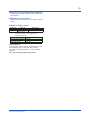
Ladder Sequence Function
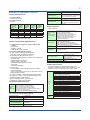
(3) Sequence Device
(1) Number of I/O Points
Number of digital input points
Number of digital output points
UP35A
Up to 8
Up to 8
Digital I/O
UP32A
Up to 5
Up to 5
Internal device
This is limited by the number of contact I/O signal
points. (See the model code.)
(2) Types of Instruction
Number of
instructions
Number of basic
instruction types
13
Number of
application
instruction types
73
Special device
Types of device
Input relay
Output relay
M relay (bit data)
DAT register (data)
P register (parameter)
K register (constant)
Special relay (bit data)
Number of points
8 (max)
8 (max)
256
28
10
30
12
Process data and process relay can be used
besides the above-mentioned.
(4) Program capacity
Max. Program capacity: 300 steps *
Remark
Load, AND, OR, Timer,
Counter, etc.
Comparison, reverse,
addition/subtraction/
multiplication/division, logic
operation, high/low limiter, etc.
*: Available number of steps differs according to the
parameters, using command and control period.
(5) Ladder computation period
Ladder computation period is the same as control
period.
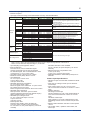
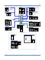
Communication Function
Function
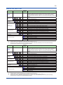
Modbus/TCP
Modbus
(RTU/ASCII)
PROFIBUS-DP
CC-Link
A standard industry
protocol allowing
communications
between the controller
and devices such as
PCs, PLCs, and DCSs.
Used for communication
between PLCs and
remote I/O, enabling
highspeed data
transmission.
DeviceNet
Peer to peer
Coordinated
Communication
PC link
Ladder
A protocol allowing
multiple controllers to
send and receive data
between one another. The
Ladder Program is used.
A protocol to coordinate
the operation of two
or more instruments
controlling the same
process.
The proprietary Yokogawa
protocol allowing
communications to PCs,
PLCs and touch panels.
A protocol to
communicate to PLCs.
Method
Interface
Server
Gateway
Ethernet
Ethernet
+ RS-485
Slave
RS-485
Slave
RS-485
Modbus
master
function
Slave
RS-485
Modbus
master
function
Slave
Modbus
master
function
Multi-drop
RS-485
RS-485
RS-485
RS-485
RS-485
(2 wire
only)
Targets
PLC and others
RS-485: UT75A/UT55A/
UT52A/UT35A/UT32A/
UP55A/UP35A/UM33A (*1)
PLC and others, UT75A/
UT55A/UT52A/UT35A/
UT32A/UP55A/UP35A/
UP32A/UM33A (*1)
PLC and others
UT75A/UT55A/UT52A/
UT35A/UT32A/UP55A/
UP35A
PLC and others
UT75A/UT55A/UT52A/
UT35A/UT32A/UP55A/
UP35A/UP32A/UM33A
PLC and others
UT75A/UT55A/UT52A/
UT35A/UT32A/UP55A/
UP35A
UT75A/UT55A/UT52A/
UT35A/UT32A/UP55A/
UP35A/UP32A
Max connection
2 connections
31 units
Communication
Data
PV, ALM etc
31 units
Number of nodes:
126
31 Units
(Main Controller is
included.)
Number of nodes: 42
(Remote device)
31 Units
(Main Controller is
included.)
Number of nodes: 64
31 Units
(Main Controller is
included.)
Read/Write: 4 units
Read only : 28 units
Master/
Slave
RS-485
UT75A/UT55A/UT52A/
UT35A/UT32A/UP55A/
UP35A/UP32A (*2)
Master : 1 unit
Slave : 31 units
Slave
RS-485
UT75A/UT55A/UT52A/
UT35A/UT32A/UP55A/
UP35A/UP32A/UM33A (*2)
31 units
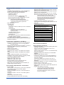
*1: UT digital indicating controller, Signal conditioner JUXTA, Power monitor POWERCERT can be connected.
*2: UT digital indication controllers can be connected.
Physical Interface
Ethernet
Standard : IEEE802.3 (10BASE-T, 100BASE-TX)
Max segment length : 100 m
Max. Connecting Configuration : Cascade Max. 4 level (10BASE-T), Max. 2 level (100BASE-TX)
RS-485
Standard: EIA RS-485
Communication method: Two-wire harf-duplex or four-wire harf-duplex, start-stop synchronization, and
non-procedural
Baud rate: 600,1200,2400,4800,9600,19200 or 38400 bps (*3)
Peer to peer communication is fixed at 19200 bps
Maximum communication distance: 1200 m
Terminating resistor: 220Ω (External)
*3: “38400 bps” is available only for UP35A (Type 3 code = 1)
All Rights Reserved. Copyright © 2010-2015, Yokogawa Electric Corporation
GS 05P02D41-01EN
Mar.31,2015-00