1
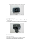
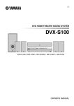
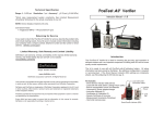
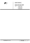
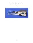
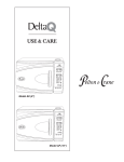
The PowerMAX Ultrasonic Scaler (PM 25&30)
User Manual
REV. 1-1-13
TPC
ADVANCED TECHNOLOGY, INC.
The Power Company
TPC ADVANCED TECHNOLOGY IN. owns all rights to this publication. The publication
should be used solely for the purpose of reference, operation, maintenance, or repair TPC
equipment. No part of this document may be reproduced or disseminated in any form or by any
means, electronically or mechanically, for other purposes.
In the event of inadvertent or deliberate publication, TPC intends to enforce its rights to this
manual under copyright law. No one may copy the materials presented in this manual without the
express written permission of TPC ADVANCED TECHNOLOGY INC.
Product specifications, as well as information presented in this manual, are subject to change
without prior notice.
PROPERTY OF TPC ADVANCED TECHNOLOGY INC.
ALL RIGHTS RESERVED
TABLE OF CONTENTS
Attention
Description of Components
I
Description of Control Panel
II
Installation
III
Operation Procedures
IV
Maintenance
V
Cleaning and Sterilization
VI
Specifications
VII
ATTENTION
Thank you for choosing TPC PowerMAX Scaler (PM 25/30KHz). Before using the unit,
please carefully read this User Manual since it contains important information including
installation procedures, operation tips and warnings.
Warnings
Important Notes!
The equipment is only to be used by a qualified doctor or dentist.
Patients with pacemakers cannot be treated with the equipment.
A shielded AC power cord must be used with this equipment.
PowerMAX should be powered from separate wall outlet with a grounding point.
I. DESCRIPTION OF COMPONENTS
Description:
Part Number:
1. Main unit in 25KHz or 30 KHz with attached handpiece
2. Foot control
3. Water line with male quick connect coupler
4. AC power line
5. Scaler Insert
PM25 / PM30
FC
WLWCCM
ACPC
S1025 / S1030
II. DESCRIPTION OF CONTROL PANEL
The function of each button or knob on the control panel is detailed below
3
1
4
2
1. ON/OFF
Indicating the main power switch. When pushed, the AC power is sent to the Main unit, and the
power indicator (LED) will be lit up. If pushed again, the power is then turned off and the power
indicator will be extinguished.
2. WATER
Indicating the water volume control knob. When turning clockwise, the water volume coming out
of the handpiece will be
decreased. Turning counter-clockwise will increase the water volume. When operating, a
continuous flow of water is
required to keep the handpiece and insert cool. Adjustment of the water flow rate controls the
water temperature, the
greater the water flow, the lower temperature and vice versa.
NOTE: Do not turn water control knob anti-clockwise repeatedly, or knob will come off.
3. POWER
Indicating the output power intensity control knob. When turning clockwise, the output power
intensity will be increased.
When turning counter-clockwise, the output power intensity will be decreased. This power
intensity control knob gives
the flexibility to adjust the output power intensity based on the difficulty of the cleaning job
(e.g., toughness of the calculus).
Label (1) means the minimum power output, and labels (3) means maximum power output
4. Indicator
This indicator represents whether the unit’s master power is on or off. Light will illuminate when
the power is on. The LED will be off when the units main power is off
NOTE: Follow power setting guidelines from insert manufacturer for different type of tips.
III. INSTALLATION
A. Safety Instructions
Grounding:
Before any connection to the output connectors is made, the unit must be connected to a
protective
earth conductor via the three-core main cable. The main plug must be inserted only into a socket
outlet
that has a protective earth contact.
Main voltage range and fuse:
Before plugging the main plug into the outlet, make sure that the instrument is suitable for local
main voltage.
The fuse holder is located on the rear panel in the main input socket. To replace a new fuse,
proceed as follow:
* Disconnect the unit from the power supply outlet
* Remove the cover of the fuse holder with a small screwdriver
* Fit a new fuse of the correct rating and refit the cover of the fuse holder
WARNING: The unit should be disconnected from the power supply outlet when replacing a fuse.
B. Installation Instructions
* Water connection: Connect the scaler’s water to a water supply with the male quick disconnect
that is at
the end of the water line.
NOTE: Water supply should be of drinking quality. Purified water or distilled water is
recommended
* Electrical Connection: Plug the foot control and AC power cord into the back of the main unit.
Then plug the
AC power line to a grounded power outlet.
* Inserts: Choose the correct INSERT for your scaler, TPC 25k (long type) inserts for your 25HKz
scaler or TPC 30k (short
type) inserts for your 30HKz scaler. The handpiece will also accept Densply and Hu-Friedy
inserts.
NOTE: When pushing the insert into the handpiece, do not put the insert all the way into the
handpiece at once. First push the insert
into the handpiece half way, step on the foot control to turn on the scaler and allow some water to
come out of the handpiece, then
push the insert all the way into the handpiece. The above procedure will help to reduce air inside
the handpiece. This will prevent the
handpiece from generating too much heat due to extra air, and thus extending the product life of
the handpiece.
IV. OPERATION PROCEDURES
•
Preparation:
Step 1: Push the POWER SWITCH to light ON indicator (LED)
Step 2: Check the water.
Step 3: Select the needed INSERT TIP, wet the O-ring then place the INSERT into the
HANDPIECE with a clockwise motion until it is fully seated.
CAUTION: Insert should be sterilized before each use.
Step 4: Set the POWER KNOB to a suitable level for the insert.
Step 5: Hold the HANDPIECE with the insert end pointing up over a suitable drain. Step on the
foot control and allow water to run
from the handpiece for a few seconds until it flows without spurting.
CAUTION: Make sure that the water spray is at the desired temperate and is reaching the
working edge of the tip.
Step 6: Place insert tip into the patient mouth and use the foot control to activate the handpiece
and water follow.
• Operation Tips:
During treatment, keep the angle between the patient’s tooth surface and the Handpiece Insert as
close to 15 degree as possible. If
the patient is not comfortable during the treatment, try the following steps.
A. When treating areas where patient is very sensitive, try to increase the Handpiece movement
speed on the surface.
B. Leave these sensitive areas for later treatment, and do other areas first.
C. If the problem persists, reduce the output power intensity of the Handpiece.
D. When operating, a continues flow of water is required to keep the Handpiece cool. The greater
the water flow, the lower the water
temperature and vice versa.
E. After six months, or if you find the output power of the Handpiece is not enough to perform
treatment, it is very possible that the
Insert is worn out. If the Insert is worn out, replace it with a new one, otherwise, have your
authorized agent provide maintainservice
to the system.
V. MAINTENANCE
The PowerMAX Scaler does not need special maintenance routine. The following daily startup/Shut-off routine and tips are useful
to extend the product life of the Scaler.
■ Daily start-up
* Turn on the water supply
* Push the MAIN POWER SWITCH to light the on indicator (LED)
NOTE: If no water comes out, please check the water supply.
NOTE: if the power LED does not light, please contact your local authorized agent.
■ Daily Shut-off
Tips:
* Place the Main Unit on an open area where air can flow freely.
* If Main Unit need to be moved, handle with care.
* Before leaving the Clinic Room, check that the AC power is turned off and the water faucet is
tightly closed.
VI. CLEANING AND STERILIZATION
In this section, we describe the procedures to clean and sterilize the scaler. It is important to
follow these procedures
before using the machine on human bodies, otherwise, patients and/or personnel may have the
possibility of infection.
It is mandatory that operators wear sterilized gloves during these procedures at all times to avoid
any possibility of
incomplete sterilization and/or infection. Below we detail the procedures for the Handpiece, the
Insert and the Main Unit,
respectively.
• Handpiece
Before cleaning, remove the Insert from the Handpiece. Let the Handpiece run for a couple of
seconds to drain out the
water and any possible contamination left inside the Handpiece. The outer surface of the
handpiece should be cleaned
with an antiseptic soap or solution. Rinse off with water and wipe or spray with a chemical
disinfectant that is compatible
with the handpiece material, such as a 1:6 dilute solution of Sporicidin brand disinfectant. A
sterilized Insert or Tip is
then reassembled to the Handpiece in preparation of the next patient.
Warning: Do not put the Handpiece and the extension wire directly into any sterilization fluid. Any
such fluid left inside
the machine will interfere with the normal operations of the system.
At the end of the day with the Insert removed, the Handpiece and cable should be scrubbed with
an antiseptic soap or
solution, and rinsed off with water.
Warning: The chemical disinfectant should not be allowed to remain on the surface longer than
the recommended time
or damage may result.
• Insert
After each usage, there may be saliva and/or blood or other debris left on the Insert,
consequently, it is necessary to
clean the Insert with a supersonic cleaner. This can be done manually by scrubbing with a brush
or by use of an
ultrasonic cleaner with a solution of detergent and water. After scrubbing the Insert should be
rinsed thoroughly with
water to remove all detergent and dried. Finally, the Insert is put into a sterilization pouch and
placed into a medical equipment
autoclave. Sterilize the Insert at 260 F (127 C) for 30 minutes or as recommended by the
manufacturer of
the particular sterilizer used.
Warning: High room temperature conditions, improper dilutions or excessive immersion time in a
chemical sterilant
can result in damage to the plastic and elastomeric materials of the Insert.
Caution: The use of a dry heat over, incompatible chemical vapor style sterilizers, quaternary
ammonium compounds,
or alcohol based compounds must be avoided as damage can result to the plastic and
elastomeric materials.
• Main Unit The Main Unit should be cleaned as follows. Carefully swab the Main Unit with
isopropyl alcohol, and keep it away from
dust.
VII. SPECIFICATION
PowerMAX Scaler is designed and manufacturers to meet the most demanding
environment. Its specification are list below:
1. Standard List
Emission:
EN55011 Class B EN60555-2 Class A
EN60555-3
Immunity:
IEC 1000-4-2 IEC 1000-4-4 IEC 1000-4-5
IEC 801-3 ENV50141
IEC 60601-1 EN1640
Safety:
2. Function List
* Scaler power control
* Water flow control * Footswitch control
* Power Turbo mode
* Power perio mode
* 25 KHz 0r 30KHz Insert Selectable (Using different Handpiece)
3. Specifications
Item
Specification
Power supply
110-125V ~ 60Hz 0.85A
Max. Output Power
24.6W (Scaling mode)
Min. Output Power
8.9W (Scaling mode)
Basic Vibration Frequency
24.5KHz (for 25KHz Insert Model)
30 KHz (for 30KHz Insert Model)
Water
• Input pressure
25-60 pounds/inch2
• Output volume
5-50ml/min
Dimension
8” (W) x 8” (D) x 3” (H)
Weight
4Kg (include handpiece)
Handpiece
Cable 250 cm
Footswitch Cable
250 cm
Environment •
Temperature
Operation: 10ºC~35ºC
Storage: 0ºC~60ºC
• Humidity Operation: 20%~80% non-condensing
Storage:
• Pressure Atmospheric pressure:
Classification:
• Class II, with transformer
• Type B
• IP40
10%~90% non-condensing
860~1060 Hpa