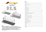
1
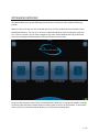
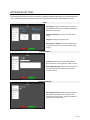
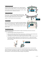
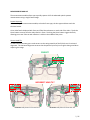
OPTIKAMPAD USER MANUAL OPTIKAMPAD INTERFACE The OptikamPad is your unique dispensing tool that helps in all aspects of the eyewear dispensing process. When you launch the app, you are presented with icons of all the modules that are available on your OptikamPad software. You can start a session in a desired module by simply touching the respective icon. Once in a session, you can freely navigate to any other module without returning to the home screen by touching the module buttons on the top-left corner of the screen. On the top left hand side of the screen, the Settings button allows you to change the software’s settings. On the top right hand side, the Help button activates a guide on the use of the software. At the bottom of the screen, the Load Session button displays a list of previously saved profiles. 1 / 27 OPTIKAMPAD SETTINGS The Settings Panel allows the user to customize numerous OptikamPad features to fit their dispensing style. The following table provides an overview of the features that are customizable by the user. Main Login/Logout: Login (or change login) to customize your OptikamPad experience and take advantage of Optikam cloud services. Relaunch Initial Setup: Launches the initial setup wizard. Language: Change the language used. Save Pictures in Memory: Select the length of time saved profiles will remain in memory before being purged. Frame Selection Facebook: Enables the use of the iPad Facebook feature whenever a frame selection profile is saved. Email Subject/Message: Represents the subject and message body of frame selection e-mails sent to customer account. Augmented Reality Blur Progressive Zones: Enables Augmented Reality live video mode progressive lens clear/blur zone simulation based on iPad tilt. See Blur Simulation in the Augmented Reality section. 2 / 27 Measurements Comfort Heights: [0 – 3mm, Default: 0mm] Automatic drop in height from pupil centre. Warnings Configuration: (Measurement Warning Panel) Clearance: [0 – 10mm, Default: 8mm]: Pupils to bottom of the lens clearance measurement warning limit Height Difference: [0 – 4mm, Default: 1.5mm] Height Left to Height Right difference warning limit. PD Difference: [0 – 4mm, Default: 2mm] PD Left to PD Right difference warning limit. High Panto: [15 – 30°, Default: 25°] High pantoscopic tilt warning limit. EY-Stick Version: Select the EY-Stick version used with OptikamPad. See EY-Stick Version Notice below. Results: (Measurement Results Panel) ERCd: Displays ERCd instead of RVD by default. The result can be toggled between ERCd and RVD by tapping on it. Print Picture: Print the measurement picture on the Measurement Report. Print Barcode: Print barcode with encoded measurement information on the Measurement Report Frame Measurement: Turn on frame measurements by default. Measured Near PD: Enable measuring of NearPD. Decentered ED Value: Alternate ED calculation that takes fitting cross decentration into account. Progressive Lens List: Select manufacturer progressive lens lists available to the associate for Lens Package overlay. Integration Lens Ordering: Enter third party lens ordering integration information. Export: Enter third party Point-of-sale measurement results export integration information. 3 / 27 Enclosure Enclosure list: Displays the list of available enclosures. Connect: Connect to the enclosure selected in the list. The light on the selected enclosure will illuminate. Confirmation that the correct enclosure has been selected is required. Disconnect: Disconnect from the selected enclosure. The enclosure will no longer be marked Assigned. Info: Display advanced enclosure information. Training Launch Training Session: This launches a training session that allows the user to practice taking a measurement picture with the help of a 3D patient animation. Training Material: Enables the user to quickly access OptikamPad help content. Internet connection is required. EY-Stick Version Notice OptikamPad version 1.3 and higher is installed with EY-Stick v3 selected as the default device. It is therefore critical that EY-Stickv2 users set the correct EY-Stick version in cases where the OptikamPad app is fully removed and re-installed, or freshly installed on a new iPad. Version 2 Version 3 WARNING: Using the incorrect EY-Stick version will result in erroneous measurements. 4 / 27 MEASUREMENTS From ONE picture, OptikamPad can obtain the following measurements: Monocular Pupillary Distance (PD) Vertex Distance (RVD) Monocular Pupillary Distance (PD) Wrap (face form tilt) Multifocal Seg Heights Pantiscopic Tilt (panto) Near PD A, B, ED and DBL values AS-WORN MEASUREMENTS The OptikamPad software will produce “as-worn” measurements. These “as-worn” measurements take monocular PDs more accurately by taking into account how the frame sits on the customer’s face. This is in contrast with the pupilometer, which captures PDs anatomically and does not take into account frame fit and nose-pad adjustments. Optikam’s EY-Stick also measures “as-worn” seg. height measurements through its unique way of capturing the patient’s natural posture. By means of a swing assembly on the EY-Stick, the optician can very quickly capture the patient’s natural head posture without being at the same eye level as the patient. This enables an optician of any height to properly and accurately measure patients of varying heights. In fact, the patient can even be sitting while the optician is standing when taking the picture. Natural Posture is reproduced when the Nasal Sensors are parallel with the primary line of sight. Sensors Horizontal Primary Line of Sight EY-STICK The EY-stick is the device used to capture all the advanced optical eyewear measurements using one single frontal image. The EY-Stick captures personalized frame fit measurements, taking into account how the frame sits on a person’s face. It is critical to properly fit the frame in the way it would be dispensed prior to performing the measurement with the EY-Stick. Posture Swing Assembly The EY-Stick consists of 4 main elements: Frame hooks Wrap Arm Vertex Distance Prism 5 / 27 Placing EY-Stick on Frame The frame hooks are located behind each leg. Extend the legs by holding the bottom edge of each leg. Insert the frame between the hooks and then close the legs to secure the frame in place, making sure that the EY-Stick is centered on the frame. Hooks Adjusting the Wrap Arm The wrap arm consists of a pivoting ledge located at the back of the EY-Stick. Looking from above, rotate the ledge back and forth until the ledge is parallel with the curvature of the eyewear. This will measure the frame wrap angle. Wrap Arm Prism Adjustment The vertex-distance prism can be moved left and right by applying a light pressure on the thumb rest. Simply move the prism to the left of the iris until the pupil is visible in the center of the prism. Also, make sure that the prism is not obstructing the frontal view of the patient’s pupil. Prism Capturing Natural Posture The patented posture swing assembly allows the height measurements to take into account the patient’s natural posture. 1. Unlock the swing assembly by lifting the break arm. 2. Make sure that the patient assumes their natural posture. Note that the patient should not be crossing their arms during this step. The patient may be sitting or standing. 3. Ask the patient to look at a far-distant object using their primary line of sight. Stand to the side of the patient and apply a slight pressure on the break arm to lock it. Now that the posture swing assembly is locked, the patient does not need to be at the same eye level as the camera lens on your Tablet. Brake Arm The patented EY-Stick ensures precise measurements by recreating the customer’s natural posture when the two green nasal sensors are in alignment. Note that locking the swing assembly in different postures will result in getting different heights. Your professional judgment should be used in ensuring that the patient is in their natural posture when locking the swing assembly. 6 / 27 MEASUREMENT MODULE The measurement module allows you to quickly capture all of the advanced optical eyewear measurements using a single frontal image. Picture Capturing When entering the measurement module, select the frame type, the lens type and then touch the Continue button. A live video feed is displayed with Focus and Take Picture buttons on each side of the video. Touch the Focus button to ensure that the video feed is in focus. Touching the Focus button triggers the flash, allowing you to see if the corneal reflection is visible in the middle of the prism. Correct Head Tilt Tilt the iPad until the two green nasal sensors on the swing assembly of the EY-Stick are in horizontal alignment. The horizontal alignment ensures that the patient’s primary line of sight is being used when capturing the image. CORRECT INCORRECT HEAD TILT Resolution: Ask patient to raise their chin Resolution: Ask patient to lower their chin 7 / 27 Alternate Positioning Method: iPad Tilting As an alternative to asking the patient to raise or lower their chin, the OptikamPad can be tilted by the operator to place the green nasal sensors in alignment. Note: OptikamPad may need to be raised or lowered to keep the customer in view. Correct Head Rotation Next, make sure that no head rotation is being introduced by ensuring that the white rotation indicator is not visible. This requires the operator to rotate the tablet left and right until the white rotation indicator is not in view. White Rotation Indicator Resolution: Turn the iPad left Resolution: Turn the iPad right 8 / 27 Patient Placement You must also make sure that the EY-Stick and the customer’s eyewear is fully visible within the blue rectangle. Once they are in alignment, ask the patient to look at the iPad’s camera lens and touch the Take Picture button while making sure to hold the iPad still. Alternatively, keep the “Take Picture” button pressed, position and stabilize the tablet, then release the “Take Picture” button when ready. The image below represents what a correct picture placement looks like prior to taking the picture. CORRECT PLACEMENT INCORRECT: SENSORS NOT IN VIEW INCORRECT: PATIENT TOO FAR Resolution: Move the iPad back Resolution: Move the iPad forward The entire eyewear and EY-Stick visible inside rectangle. The two green nasal sensors are aligned. There is no head rotation (the white rotation indicator is fully hidden behind the brake arm) 9 / 27 Image Verification Once the picture is taken, the measurement picture is displayed. Please take a moment to analyze the image to verify that the pre-fit was properly performed. On the measurement image, the software draws the following measurement markers: a horizontal line, two vertical lines, two pupil markers, and a marker on the reflection of the pupil inside of the prism. The OptikamPad software attempts to automatically place all markers in their correct position and will display in Red markers not automatically detected. Please perform the following verifications. Verify that the horizontal line is placed on the inner edge of the frame where the frame and the lens come together. Verify that the vertical lines are placed on each side of the bridge, ensuring that the same reference point is used on both sides. Do not use the nose pads as a reference point, as they change with the fitting. Verify the markers on the pupils. Note that on the side where the prism is located, two reflections are formed on the pupil. Verify that the marker is on the nasal most reflection. This also applies to the pupil reflection inside of the prism. On the left eye, verify that the marker is positioned on the corneal reflection. 10 / 27 Explanations of Errors and Warnings When capturing a measurement image, possible Errors and Warnings may appear. Below, is a complete listing of each with their respective description. Picture Taking Error Analysis OptikamPad may reject the image based on one of the following reasons: Head Rotation Error Head Tilt Error The customer's face was rotated left or right beyond acceptable limits(white rotation indicator visible) The customer's face was tilted up or down beyond acceptable limits(green nasal circles not aligned horizontally) The EY-Stick was not within the blue rectangle when the picture was taken. Wrap arm indicates negative wrap angle. (Wrap arm not set properly) Picture taken with prism in the parked position. Detection Error Red X on Wrap Sensor Red X on Prism Sensor NOTE: The picture must be re-taken to continue the measurement process. (If Wrap and RVD measurement necessary) Once the picture is taken correctly, OptikamPad may generate the following warnings: (visible in the top left corner of the image) Warning Verify Fitting (PD) Verify Fitting (Height) Verify Clearance Description PDL and PDR differ beyond the set warning limit. (Default PD difference: 2.0mm ) Minimum Height Check RVD out of Range Verify pre-fit. (Default Height difference: 1.5mm) Verify EY-Stick is properly seated on the frame. Verify pre-fit. The clearance between the pupils and the bottom of the frame is below the set warning limit. Verify pre-fit. Verify natural posture. HL and HR differ beyond the set warning limit. (Default Clearance: 8mm) Verify Panto Possible Action (Default High Panto: 25°) Verify EY-Stick is properly seated on the frame. Verify natural posture. Lens package does not satisfy the minimum fitting height. Select a different lens package The customer pantoscopic tilt is beyond the set warning limit. Pupil is not visible within the prism or the cursor is not placed on the corneal reflection Retake picture or reposition the pipil reflection Warnings do not indicate error but simply suggest areas that should be checked. NOTE: OptikamPad warning limit values can be changed or disabled in Settings Measurements Warning Configuration. 11 / 27 Marker Placement If you spot a displaced marker, adjust its position by first selecting the marker. Selecting a marker is done by touching the two square anchors in the case of the lines, or on the crosshairs in the case of the pupils. Once a marker is selected, there are three ways to adjust its position. Drag outside of the directional ring to slide the marker in place Tap anywhere inside the ring to move the maker to a specific spot Use the arrows to make fine adjustments. Quickly navigate through the different markers using the Next and Previous buttons on each side of the picture. When all of the markers have been set, return to the full view mode by touching the Unselect button. Now you have all of the measurements needed to order your lenses. 12 / 27 Frame Measurements Frame measurements can also be captured by touching on the “Tap to Enable Frame Measurements” area of the results panel. This displays a green corner shape and a yellow circle. Perform the following steps to obtain Frame Measurements: Place the green corner such that the horizontal segment is placed at the top of the lens and the vertical segment is placed on the temporal side of the lens. This completes the boxing of the lens. Change the size of the yellow circle by dragging the Effective Diameter slider at the bottom right hand side of the screen so that the lens fits inside the smallest sized circle. The A, B, ED and DBL frame measurements are displayed on the right side of the results bar. Lens Thickness Now that the Frame Measurements are complete, the Lens Thickness button becomes available in full view mode. In the Lens Thickness demo, drag the Rx slider to select the patients’ approximate prescription. This displays the difference in thickness between a 1.5, 1.6, 1.67 and 1.74 lens using the patient’s Pupillary Distance measurements and their frame measurements. Exit by touching the ‘X’ button at the top right hand side of the Lens Thickness window. 13 / 27 Lens Packages You can also touch the Lens Package button to verify whether the chosen Lens Package respects the minimum fitting height and whether the lens cuts-out correctly. NearPD Measurements NearPD measurements are calculated based on the Far PD picture by default. Optionally, NearPD measurement can be performed with a 2nd front camera picture. Enable NearPD measurements in the Settings panel Tap the NearPD button to perform measurement 14 / 27 Move the prism all the way to the left, it will not be required for NearPD measurement. Hand the iPad to the customer. Have them hold it as if they are reading a book. Tap the focus button to auto-focus the camera and adjust the image for lighting conditions. Instruct the customer to move the iPad closer or further away from their face until the correct reading distance is indicated in the bottom left corner of the screen. Each time the reading distance is changed, the customer must hold still for three seconds to allow OptikamPad to re-calculate the new value. Ensure that the customer is focusing on the red dot at the bottom of the screen. When ready, tap the Take Picture button. Focus Take Picture Focus dot Reading Distance Verify that the vertical lines are placed on each side of the bridge, ensuring that the same reference point is used on both sides. Do not use the nose pads as a reference point, as they change with the fitting. Pupil Markers Verify that the pupil markers are placed at the center of each pupil. Tap the Lighten button to increase the image contrast. This will make the iris more distinguishable from the background image. Vertical Lines 15 / 27 The NearPD results including the NearPD corridor measurements are displayed in the results panel at the top of the screen. Tap the NearPD result to toggle between NearPD (measurement based solely on NearPD picture) and Proportional Near PD (NearPD measurement derived from FarPD monocular and NearPD convergence values). Additionally, the reading dot is overlaid on the FarPD picture. NearPD Results NearPD results including corridor values Reading dot Measurement Training Session Training Session mode has been added that allows you to practice taking a measurement picture with the help of a 3D patient animation. The Training Session is accessed from the Settings screen by entering the Training tab and tapping the “Launch Training Session” button. 16 / 27 Start the session by selecting a Frame Type and a Lens Type. Tapping the Continue button will present the 3D patient wearing an EY-Stick. A slider at the bottom of the screen allows practicing adjusting the prism location on the EY-Stick. The Focus button will simulate a Flash firing and allows the user to determine proper prism placement via the corneal reflections. 3D Patient The user can practice taking a picture one of two ways: Prism Slider Method #1: Touch and Drag Touch and drag left or right on the 3D patient to rotate the patient’s head. Dragging up and down tilts the head up and down. You will notice that the Picture Assist Instructions will change while you are dragging. This method allows a user to quickly learn how the green nasal sensor alignment and White Rotation Indicator requirements are used to properly take an image with OptikamPad. Picture Assist Instructions 17 / 27 At any time the user can press the Take Picture button. It may be helpful for the user to take pictures and intentionally introduce various head rotations and head tilts to get more familiar with OptikamPad’s tolerances and image errors. Method #2: Chessboard Pattern Download and print the following Chessboard pattern: www.optikam.com/assets/chessboard.jpg This chessboard allows OptikamPad to track your iPad camera movements to move the 3D patient. This allows a user to practice the iPad’s movements when taking a measurement image. Simply fix the chessboard pattern on a wall and point the iPad camera at it as if it were a real patient. A small video preview window is available to the user to help them ensure that the chessboard pattern is visible to the iPad camera. Picture Assist Instructions Video Preview As the iPad is moved, the 3D patient’s head position will change. The Picture Assist Instructions will also assist the user in determining the correct positioning. 18 / 27 At any time the user can press the Take Picture button. The user can then perform all of the measurement steps on the 3D patient and save the training session for future reference. 19 / 27 LENS DEMOS The Lens Demos module allows you to demonstrate the advantages of premium lens options in a quick and interactive way. The demos can be navigated by touching the lens options at the top and suboptions on the right hand side. Touching the MENU button expands and collapses the list of lens options. The following demos are available: High-Index AR Coating Photochromic Lenses Polarized Lenses Progressive Lens Designs Color Tints Touching and dragging the lens in each demo will interactively showcase lens benefits in various settings. 20 / 27 FRAME SELECTION The Frame selection module enables customers to see how they look like in different eyewear. The side-by-side image comparison exposes the customer to frames of different styles, resulting in an increase in multiple-frame sales. To use this module, simply touch one of the four quadrants to activate live video. Once the patient is in view, touch on the live video feed once ready to capture the image. This process may be repeated in the other quadrants. You can Email customers their pictures by touching the Email button located at the bottom right hand side of the screen. An e-mail account must first be configured on the iPad in order to use this function. You can clear the pictures by touching the clear button. 21 / 27 Full Screen Full-screen is performed with a double-tap on any of the four quadrants. When in full view, swipe the images to scroll through them. Split screen view is returned to by double tapping the full screen image. Pan & Zoom Pinch gestures can be used to zoom in an image in one of the 4 quadrants or a full screen image. 22 / 27 AUGMENTED REALITY When launching the Augmented Reality module you are presented with two live video windows. Below each video window, several lens options can be selected: the lens type, the coating, the tints and colors. This live simulation showcases the benefits of various lens options using your office setting. Point the iPad around different parts of your office to highlight various lens benefits. Scenes You can select pre-loaded scenes which simulate lens options in a 3D environment using the buttons on the left side of the screen. You can move around the scene by touching and dragging on the picture. Performing a pinch gesture will zoom in and out of the scene. Hotspots In each scene, a list of Hotspots are available on the right side of the screen that allow you to instantly pan the lens to specific location. This allows you to quickly illustrate lens benefits in meaningful areas of the scene. Split Screen Mode Interface Scene Selection Full Screen Mode Hotspot Navigation Full Screen Mode Show/Hide Lens outline 23 / 27 Full-Screen Tapping the Full Screen icon will enlarge one of the lens views to full-screen. The user can quickly be shown the differences between the top and bottom lenses by tapping the Top Lens/Bottom Lens buttons. Split screen mode is returned to by tapping the Split Screen button. Full Screen Mode Interface Hotspot Navigation Scene Selection Split Screen Mode Top/Bottom Lens Select Show/Hide Lens outline 24 / 27 3D Eyewear Scene Tapping the “Eyewear3D” button will launch the 3D Eyewear scene that helps showcase the benefits of High-Index lenses, AR coating and color tints. 3D Eyewear 3D Eyewear frame color can be changed by performing a right or left two-finger swipe gesture on top of the 3D image. 3D Eyewear frame type can be toggled between rimless and metal by performing an up or down twofinger swipe gesture on top of the 3D image. Two-finger swipe left or right to change frame color Two-finger swipe up or down to change frame type 25 / 27 3D Eyewear can be displayed without the patient by taping on the ‘Eyewear Only’ button. 3D Eyewear with patient 3D Eyewear without patient To exit the Augmented Reality module tap the Close button located at the bottom-left corner of the screen. 26 / 27 Blur Simulation This feature must be enabled in Settings Augmented Reality. It simulates the progressive lens blur/clear zones based on iPad tilt. This simulation is only available in Augmented Reality live video mode. iPad Tilt Zone blurring Reading Distance Clear Zone Mid Distance Clear Zone Far Distance Clear Zone 27 / 27