1
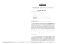
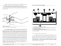
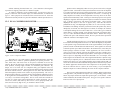
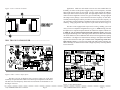
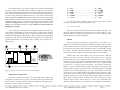
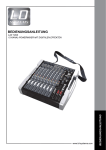
Film-Tech
The information contained in this Adobe Acrobat pdf
file is provided at your own risk and good judgment.
These manuals are designed to facilitate the
exchange of information related to cinema
projection and film handling, with no warranties nor
obligations from the authors, for qualified field
service engineers.
If you are not a qualified technician, please make no
adjuatments to anything you may read about in these
Adobe manual downloads
www.film-tech.com
ASHLY
POWERCARD AMPLIFIER INPUT OPTIONS
ITC-2, CL-2, XR-1, MM-6
TABLE OF CONTENTS
Installation ....................................................................... 2
ITC-2 Input Transformer ................................................. 3
CL-2 Limiter .................................................................... 4
XR-1 Crossover ............................................................... 6
MM-6 Mixer .................................................................... 9
Specifications .................................................................. 14
INTRODUCTION ....................................................................
Amplifier input options evolved with the demand for precise, functional, yet
economical and application-specific hardware. Ashly POWERCARD input
options benefit from over twenty years of designing and manufacturing outboard
signal processing, such as mixers, equalizers, compressor/limiters, and crossovers. This same quality and experience is combined with our MOSFET power
amplifiers to achieve practical solutions for specific audio needs. These products
are especially useful for many “set and forget” applications, where constant
adjustment of controls is unnecessary. Some models feature recessed controls to
discourage tampering, while the mixer option can be adjusted by hand. All input
options are installed within the walls of the amp chassis, minimizing the risk of
accidental mechanical damage. These options are compatible with all current and
future Ashly amplifiers except for the single rack space SRA-120.
UNPACKING............................................................................
As a part of our system of quality control, every Ashly product is carefully
inspected before leaving the factory to ensure flawless appearance. After
unpacking, please inspect for any physical damage. Save the shipping carton and
all packing materials, as they were carefully designed to reduce to minimum the
possibility of transportation damage should the unit again require packing and
○ ○ ○ ○ ○ ○ ○ ○ ○ ○ ○ ○ ○ ○ ○ ○ ○ ○ ○ ○ ○ ○ ○ ○ ○ ○ ○ ○ ○ ○ ○ ○ ○ ○ ○ ○ ○ ○ ○ ○ ○ ○ ○ ○ ○ ○ ○ ○ ○ ○ ○ ○ ○ ○ ○ ○ ○ ○ ○ ○ ○ ○ ○ ○ ○ ○ ○ ○ ○ ○ ○ ○ ○ ○ ○ ○ ○ ○ ○ ○ ○ ○ ○ ○ ○ ○ ○ ○
Ashly POWERCARD Owners Manual
Page
Ashly POWERCARD Owners Manual
Page 1
shipping. In the event that damage has occurred, immediately notify your
dealer so that a written claim to cover the damages can be initiated.
The right to any claim against a public carrier can be forfeited if the carrier
is not notified promptly and if the shipping carton and packing materials are not
available for inspection by the carrier. Save all packing materials until the claim
has been settled.
ITC-2 INPUT TRANSFORMER ............................................
!
"
#
Signal Connector
(Observe Polarity)
Power Suppl y Connect or
(Location may vary)
Ground Connector
(Location may vary)
INSTALLATION ......................................................................
Figure 1: Input option removal and assembly
Before installing an input option, be sure to disconnect the amplifier from
power. To remove the standard input panel, unscrew the four corner screws and
gently pull the assembly out. There will be two terminals already connected and one
remaining disconnected. The two 3-conductor shielded wires which terminate at the
six pin header are the audio signal paths to the amplifier. Slowly rock the connector
back and forth while exerting a constant pull and it will come right off. Note that there
is a friction lock tab and ramp on the header set, indicating proper polarity during
reassembly. The black wire terminated with a spade fast-on is the chassis ground.
This is connected to the PCB via a riveted fast-tab. If during reassembly this fast-on
feels loose, remove and squeeze the blue spade with pliers to assure good contact. The
last connector, the power supply, is shipped disconnected because the standard input
is passive. Depending on the amp model, these three wires will be either red, violet,
and black, or blue, blue, and yellow. The three pin power supply header set is
polarized for proper mating. Once these three connectors are plugged into the new
option, gently replace the panel and screws.
$
1.)
2.)
3.)
4.)
5.)
6.)
Channel one optional transformer socket.
Cut and remove these two jumpers before inserting channel one transformer.
Signal header connector
Channel two optional transformer socket.
Cut and remove these two jumpers before installing channel two transformer
Ground connector
Figure 2: Input transformer assembly diagram
The transformer input option may be installed in either channels 1 or 2 or
both. The input transformer provides complete electrical isolation between the
amplifier and its signal source to eliminate any ground-induced hum noise. The
transformer input also further reduces any common-mode noise and radio
frequency interference. The precision 1:1 transformer will not affect any controls
on the standard input. Input attenuation occurs prior to the primary windings,
allowing for high level input signals
○ ○ ○ ○ ○ ○ ○ ○ ○ ○ ○ ○ ○ ○ ○ ○ ○ ○ ○ ○ ○ ○ ○ ○ ○ ○ ○ ○ ○ ○ ○ ○ ○ ○ ○ ○ ○ ○ ○ ○ ○ ○ ○ ○ ○ ○ ○ ○ ○ ○ ○ ○ ○ ○ ○ ○ ○ ○ ○ ○ ○ ○ ○ ○ ○ ○ ○ ○ ○ ○ ○ ○ ○ ○ ○ ○ ○ ○ ○ ○ ○ ○ ○ ○ ○ ○ ○ ○
Ashly POWERCARD Owners Manual
Page 2
Ashly POWERCARD Owners Manual
Page 3
without saturating the transformer core. (Core saturation is the magnetic
equivalent of clipping, and results in a distorted signal)
To install a transformer in the standard input, cut and remove the two
jumpers (solid color with one black stripe) for each transformer, as indicated in
figure 2. These jumpers are referenced on the circuit board as well. Insert the
transformer assembly into the five pin socket and fasten with the provided screws.
CL-2 DUAL COMPRESSOR/LIMITER ..............................
Figure 3: CL-2 compressor/limiter
The Ashly CL-2 is a peak-sensitive, adjustable threshold AGC (automatic
gain control) device which is optimized primarily for speaker protection. It's
ratio, attack time, and release time are all preset at desirable levels for this
purpose. We use the same VCA (voltage controlled amplifier) found in our other
AGC products, assuring highly accurate, low distortion gain reduction. By
design, our VCA circuit acts as a transparent unity gain amplifier unless it's
detector threshold is exceeded. You can select the input signal level below which
the limiter remains inactive. When signal level rises above this threshold, the
limit LED lights up and the VCA reduces it's gain proportionally. The ratio, or
amount of gain reduction vs. signal level above the threshold, gradually increases
as the signal above threshold increases. This technique has become known as
"over-easy" or "soft knee" among others. The CL-2 ratio settles in at around 10:1
for more of a "brick wall" limiter appropriate for speaker protection. It's fast
attack time (1mSec) and relatively slow release (1.5sec) properly handle transients and excessively high levels, yet maintain a natural sound.
Speakers can be damaged by either excessive power or more often, a clipped
signal waveform. This kind of sound system distortion occurs when an amplifier
is overdriven and runs out of power during peak signals. In this case, nice round
waveforms turn into harsh sounding squared-off waveforms. Overdriving an
Ashly amplifier will usually be inconsequential to the amp, however the loudspeaker load will ultimately suffer. Looking at it from the perspective of a speaker
diaphragm, clipped or distorted operation requires an instant acceleration, instant
stop, a change of direction, and instant acceleration again. Since speaker
diaphragms are subject to the laws of physics, they won't take this kind of
punishment for long. The diaphragm may shatter, or it's voice coil may overheat.
In addition to the damage caused by sustained overload, the speaker may also be
damaged by occasional, one-shot high level overload, for example, the sound of
a microphone falling face first onto a hard floor. Even if this type of transient
doesn't destroy a speaker outright, it may damage the speaker surround in such a
way as to cause mechanical abrasion and future failure. Rather than occupy
valuable rack space with outboard limiters, the CL-2 provides driver protection
within the confines of the amplifier itself.
Another application for the CL-2 is to reduce the dynamic range of a signal
in environments with high ambient noise levels. When intelligibility is important,
a wide dynamic range would render much of the signal inaudible, as the quieter
portions of audio would fall below the ambient noise. If the signal were increased
so that the quietest part could be heard above the ambient noise, most likely the
loudest passage would be too loud. In this application, the CL-2 becomes a
compressor because it literally squeezes the dynamic range into a smaller space.
The difference between the loudest signal and the softest signal is reduced by a
factor of up to ten, depending on where the threshold is set. For example, if the
loudest signal were 50 dB above the softest signal (FM radio has a dynamic range
of 60) and you adjusted your CL-2 threshold control so that the LED threshold
indicator was always on, your resulting dynamic range would be about 5dB. Of
course this is a bit extreme but it illustrates the application. Induction loop systems
are another application which benefit from compression of the dynamic range.
The level control on the CL-2 follows the VCA circuitry, so you can adjust the
amplifier output level without affecting the action of the compressor/limiter.
Stereo, mono, and bridged mono modes are available. When in either mono
or bridged mono, only channel one input is used. The grounding jumper on the
barrier strip input connects the input cable ground (pin 1) to the chassis. Under
normal conditions, this should be left in place. See figure 4 for specific connector
locations of the CL-2 input option.
○ ○ ○ ○ ○ ○ ○ ○ ○ ○ ○ ○ ○ ○ ○ ○ ○ ○ ○ ○ ○ ○ ○ ○ ○ ○ ○ ○ ○ ○ ○ ○ ○ ○ ○ ○ ○ ○ ○ ○ ○ ○ ○ ○ ○ ○ ○ ○ ○ ○ ○ ○ ○ ○ ○ ○ ○ ○ ○ ○ ○ ○ ○ ○ ○ ○ ○ ○ ○ ○ ○ ○ ○ ○ ○ ○ ○ ○ ○ ○ ○ ○ ○ ○ ○ ○ ○ ○
Ashly POWERCARD Owners Manual
Page 4
Ashly POWERCARD Owners Manual
Page 5
Figure 4: CL-2 connector locations
applications. While our rack-mount crossovers use state-variable filters for
flexibility, the nature of this product suggests using two fixed-frequency cascaded
butterworth response filters for each output. The low output includes an 18dB/oct.
20Hz hipass filter to reduce subsonic signal. The high output includes 360° of phase
control for driver alignment as well as two types of CD horn EQ. A single eight pin
SIP (single in-line package) resistor network selects the frequency for each filter.
Normally both the high-pass and low-pass filters are tuned to the same frequency, so
one value SIP is used for both filters. Installation of the resistor networks requires no
soldering - simply plug them in their respective 8 pin sockets as shown in figure 6.
XR-1 TWO-WAY CROSSOVER ...........................................
The XR-1 comes equipped with output mode switching, enabling you a wide
variety of crossover/amplifier configurations (see figure 5). Mode 1 simply forwards
the high crossover output to amplifier channel one and the low output to channel two.
In Mode 1A, you can replace the high output with a full range signal by depressing
the Highpass/Full Range switch. Full range speaker cabinets are connected to channel
one while channel two drives additional subwoofers for those applications requiring
extended bass. The high level control becomes full range, while phase and CD Horn
EQ are removed from the audio path. Caution: never send full range audio into a
high frequency driver! To prevent a stray hand from inadvertently switching your
horn to full range, the button for this control is shipped seperately in the bag with the
resistor networks.
Figure 6: XR-1 crossover input option
The XR-1 two-way 24 dB/octave active crossover places one of the most
commonly used pro audio tools within one of the best power amplifiers on the market.
The XR-1 uses fixed-frequency filters and recessed controls for the ultimate in "set
and forget" crossover
○ ○ ○ ○ ○ ○ ○ ○ ○ ○ ○ ○ ○ ○ ○ ○ ○ ○ ○ ○ ○ ○ ○ ○ ○ ○ ○ ○ ○ ○ ○ ○ ○ ○ ○ ○ ○ ○ ○ ○ ○ ○ ○ ○ ○ ○ ○ ○ Figure
○ ○ ○ ○5:○ XR-1
○ ○ ○ Output
○ ○ ○ ○Modes
○ ○ ○ ○ ○ ○ ○ ○ ○ ○ ○ ○ ○ ○ ○ ○ ○ ○ ○ ○ ○ ○ ○ ○ ○ ○ ○ ○
Ashly POWERCARD Owners Manual
Page 6
Ashly POWERCARD Owners Manual
Page 7
In a biamped system, low frequency audio power typically outweighs high
frequency power by a significant margin, depending on efficiency of the speakers.
For example, a biamped system might require 300 watts for the low end but only 100
watts or less for the high frequency drivers. This is because high frequencies convert
to acoustic energy much more efficiently than lows. So in order to avoid wasting
unused amplifier power, Mode 2 allows the low output of the crossover to drive both
amplifier channels, while the aux high output is used to drive a less powerful amplifier
for the high frequency drivers. If even more low frequency power is required, switch
to Mode 3 for bridged low out operation. Bridged output is taken from the two red
binding posts, with channel two as the (+) signal. Caution: never connect either red
binding post to ground!
The aux out jacks access the crossover outputs just prior to their respective
level controls, and although they are not affected by these controls, they contain all
of the respective processing of their filter, ie. 20Hz low-cut filter on the low output,
and phase and CD horn EQ on the high output. The aux outputs are pseudo-balanced
tip-ring-sleeve and while not electrically balanced, have the same common mode
rejection characteristics as full balanced lines, providing they terminate into a
balanced input.
Fc = 80Hz . . . . . . . . . . . . . . . . . . . . . . . . . . . . .Rf = 140KΩ
Ω∗
Fc = 160Hz . . . . . . . . . . . . . . . . . . . . . . . . . . . . Rf = 68KΩ∗
Ω∗
Fc = 500Hz . . . . . . . . . . . . . . . . . . . . . . . . . . . . Rf = 22KΩ∗
Fc = 750Hz . . . . . . . . . . . . . . . . . . . . . . . . . . . . Rf = 15KΩ
Ω∗
Fc = 1.2KHz . . . . . . . . . . . . . . . . . . . . . . . . . . . Rf = 10KΩ∗
Fc = 1.6KHz . . . . . . . . . . . . . . . . . . . . . . . . . . . Rf = 6.8KΩ
If you wish to choose a different crossover point, start with the desired
frequency and compute the following equation for Rf:
Fc = 1/ (8.88 x 10⁻⁸) Rf
Where Fc is the desired crossover point and Rf is the SIP network value. You
may have difficulty finding the correct SIPS at your local parts dealer, so if you
absolutely must have a different frequency than one we have available, consult
with the factory for possible further help.
PHASE
When two identical waveforms are superimposed over each other, or in
phase, they will simply add to each other and double in amplitude. Thus, each XR1 filter is 6dB down at the crossover point so that addition of both highpass and
lowpass filters yields a flat response through the crossover region (6dB is double
the voltage). Therefore, the signal coming out of the amplifier is summed flat
because the two filter outputs are electronically in phase with each other.
Figure 6: XR-1 connector and resistor network locations
FREQUENCY SELECTION
The XR-1 is supplied with three* sets of matched resistor SIPS which
correspond to popular crossover points. Each SIP contains four identical and
discrete resistors. The other selected values are available by calling the factory.
The values we have chosen are as follows:
Problems may occur when speaker voice coils are placed at a different
distance to any given set of ears. Since the high frequency driver is typically
located behind the woofer, identical signals at each driver (at the crossover
frequency) are converted to soundwaves which ultimately interact with each other
in the form of phase cancellation. In other words, while in-phase signals will add
to each other, out-of-phase signals will subtract. The degree to which they
subtract, or cancel, is determined by their phase relationship. O° means precisely
in phase, while 180° results in total cancellation. A 500Hz signal has a wavelength
of about two feet, so if the high frequency voice coil is offset from the woofer voice
coil by one foot, the two signals will be acoustically half of the waveform, or 180°,
out of phase. You can correct for this by changing the electrical phase of the high
frequency signal by 180° so that the high and low signals will be acoustically in
phase. Keep in mind that there are many other factors contributing to phase
distortion which we have little control over, such as horn construction and
materials, cabinet resonance, room reflections, even temperature and humidity.
○ ○ ○ ○ ○ ○ ○ ○ ○ ○ ○ ○ ○ ○ ○ ○ ○ ○ ○ ○ ○ ○ ○ ○ ○ ○ ○ ○ ○ ○ ○ ○ ○ ○ ○ ○ ○ ○ ○ ○ ○ ○ ○ ○ ○ ○ ○ ○ ○ ○ ○ ○ ○ ○ ○ ○ ○ ○ ○ ○ ○ ○ ○ ○ ○ ○ ○ ○ ○ ○ ○ ○ ○ ○ ○ ○ ○ ○ ○ ○ ○ ○ ○ ○ ○ ○ ○ ○
Ashly POWERCARD Owners Manual
Page 8
Ashly POWERCARD Owners Manual
Page 9
The simplest solution is to physically align the voice coils, but when this is
impractical the XR-1 allows you to adjust the phase of the high frequency output.
To do nothing to the phase, leave the control at 0. To achieve best results when
aligning drivers, we encourage you to use appropriate audio measurement tools
when configuring the system.
CD HORN EQ
CD horn EQ is simply a 6dB/oct. high frequency shelving filter to compensate constant directivity horn designs for flat, on axis response. The XR-1 allows
you to switch frequencies depending on the horn size your application requires.
Use the low frequency for larger, lower frequency horns, and use the high
frequency for smaller, higher frequency horns.
MM-6 MIC/LINE MIXER ......................................................
devices, such as equalizers. +15 Volt phantom power is available for use
with most condenser mics by switching an internal jumper (no soldering
required).
See figure 9 for location of the phantom power switch. An LED
indicates the on/off status of phantom power.
MIC INPUTS
The microphone inputs are balanced, with an initial gain of 20dB, and a
maximum input level of 0dBu. Any signal above this level will clip the input
stage and become distorted. The mic level controls add up to an additional 15.6dB
of gain to the mic signal. The master level control then adds up to an another
15.5dB to the signal, at which point the signal is sent off to the amplifier. Since
there are no clipping indicators on this product, a little common sense and
attention to gain stage detail will prevent unnecessary clipping. Each mic input
is routed to both amplifier channels. It is not possible to select one mic to one
channel and the other mic to a different channel.
LINE INPUTS
The line level controls passively attenuate the signal prior to its reaching
the summing bus. This means that the line level inputs are not limited by a
maximum input level. If the amplifier is well within it's power range and yet the
sound is distorted, chances are that somewhere in the MM-6 the signal is too hot.
A good starting point, for both line and mic inputs, is to set the master level at
5 and then increase the level controls until the desired volume is reached.
If the amplifier is configured in stereo mode, line input channels one and
three are routed to amplifier channel 1, while channels two and four correspond
to amplifier channel 2. When in mono/normal or bridged/mono mode, the stereo
signals are summed together, effectively giving you four mono line inputs as well
as the two mic inputs.
Figure 7: MM-6 mic/line mixer
The MM-6 is a practical solution to one of the most fundamental needs in
INSERT POINTS
audio . . . control the volume of several voice and program signals and amplify
them to a loudspeaker. Combined with any of our PowerCard compatible
Insert points are available for each output channel of the mix. Should you
amplifiers, this handy tool eliminates the need for outboard mixers in many
wish to use an external processing device such as an equalizer, compressor, noise
applications. You can run two microphone inputs and up to four line level inputs,
gate, tape deck, or even another amplifier, the insert points allow you full access
each with a discrete level control. The two microphone inputs have a switchable
to
200Hz low-cut filter to reduce wind, floor, or breath noise. Insert points are
available
for interfacing with external
○ ○ ○ ○ ○ ○ ○ ○ ○ ○ ○ ○ ○ ○ ○ ○ ○ ○ ○ ○ ○ ○ ○ ○ ○ ○ ○ ○ ○ ○ ○ ○ ○ ○ ○ ○ ○ ○ ○ ○ ○ ○ ○ ○ ○ ○ ○ ○ ○ ○ ○ ○ ○ ○ ○ ○ ○ ○ ○ ○ ○ ○ ○ ○ ○ ○ ○ ○ ○ ○ ○ ○ ○ ○ ○ ○ ○ ○ ○ ○ ○ ○ ○ ○ ○ ○ ○ ○
Ashly POWERCARD Owners Manual
Page 10
Ashly POWERCARD Owners Manual
Page 11
the signal both in and out of the mixer/amplifier combination. The insert
points are interrupting, meaning the insertion of a plug will interrupt the signal
going to the amplifier. The tip is the return, or input to the amplifier, while the ring
is the send, or output of the mixer.
EXTERNAL PROCESSING
To place an external processor in the loop, first you need to obtain or make
a special three conductor cable which is terminated on one end with a stereo TRS
(tip-ring-sleeve) 1/4" plug, and terminated on the other end with two mono TS (tipsleeve) 1/4" plugs. The shield at the TRS end must connect to the sleeve of each
mono plug. The tip from the insert point connects to one mono tip (return), while
the ring (send) from the insert point connects to the other mono plug's tip (see
figure 8). Remember to identify which mono plug is send and which is return. As
these are unbalanced signals, avoid running them more than ten or fifteen feet to
the outboard processor. Any greater distance may increase hum susceptibility. If
at all possible, always mount external processing in the same rack as the power
amplifier to minimize the chance for ground loops in the system.
AUX OUTPUTS
Figure 8: Insert point cables
If you wish to tap the mixer's output for external use without disturbing the
signal sent to the amplifier, as in driving a tape deck or auxiliary amplifier, the
procedure is similar. Make a cable with a stereo plug on one end, only connect
together the tip and the ring. This is the hot signal to whatever device you are
driving. Keep the cable length to a minimum and avoid ground loops by the same
techniques as mentioned above. Connect the shield to the sleeve as you would any
signal cable and terminate it at the other end according to your needs.
MIXER OVERRIDE
You can override the mixer by simply inserting a mono plug with your
external source on the tip. This feeds directly to the power amplifier without any
level control on the amp itself. Again, this is an unbalanced input, so follow the
techniques mentioned above for minimum noise and ground loop hum.
Figure 9: MM-6 connector and jumper locations
○ ○ ○ ○ ○ ○ ○ ○ ○ ○ ○ ○ ○ ○ ○ ○ ○ ○ ○ ○ ○ ○ ○ ○ ○ ○ ○ ○ ○ ○ ○ ○ ○ ○ ○ ○ ○ ○ ○ ○ ○ ○ ○ ○ ○ ○ ○ ○ ○ ○ ○ ○ ○ ○ ○ ○ ○ ○ ○ ○ ○ ○ ○ ○ ○ ○ ○ ○ ○ ○ ○ ○ ○ ○ ○ ○ ○ ○ ○ ○ ○ ○ ○ ○ ○ ○ ○ ○
Ashly POWERCARD Owners Manual
Page 12
Ashly POWERCARD Owners Manual
Page 13
CL-2: Limiter Option
SPECIFICATIONS
ITC-2: Input Transformer Option
Input Type . . . . . . . . . . . . . . . . . . Transformer balanced
Input Impedance . . . . . . . . . . . . . . >20KΩ
Max Input to transformer . . . . . . . +7 dBu (transformers follow input
attenuators)
Insertion Loss . . . . . . . . . . . . . . . . 0 dB ±0.3dB at 1KHz
Frequency Response . . . . . . . . . . ±0.3dB 20Hz-20KHz
THD . . . . . . . . . . . . . . . . . . . . . . . .007% at 1KHz and +7 dBu
.1% at 40Hz and +7dBu
IM Distortion (SMPTE) . . . . . . . . .1% at +7 dBu
Shielding . . . . . . . . . . . . . . . . . . . . Complete 24 gauge mu-metal enclosure
Input Type . . . . . . . . . . . . . . . . . .
Input Impedance . . . . . . . . . . . . . .
Maximum Input Level . . . . . . . . .
Limit Threshold Range . . . . . . . .
Limit Ratio . . . . . . . . . . . . . . . . . .
levels
Attack Time . . . . . . . . . . . . . . . . .
Release Time . . . . . . . . . . . . . . . .
Frequency Response . . . . . . . . . .
THD . . . . . . . . . . . . . . . . . . . . . . .
Limiter Output Noise . . . . . . . . . .
Active Balanced
20KΩ
+18dBu
-28dBu to +18dBu
Approx. 10:1, increasing at higher input
1 msec
1.5 sec
±.2dB 20Hz-20KHz
<.05% 20Hz-20KHz at +7dBu
<-90dBu, 20Hz-20KHz unweighted
MM-6: Mic/Line Mixer Option
XR-1: Crossover Option
Input Type . . . . . . . . . . . . . . . . . .
Input Impedance . . . . . . . . . . . . . .
Maximum Input Level . . . . . . . . .
Crossover Filter Types . . . . . . . . .
Frequency Response . . . . . . . . . .
Crossover Frequencies . . . . . . . . .
Active Balanced
20KΩ
+20 dBu
24 dB/Octave Butterworth
±.5 dB within passbands
Internally selectable at
160Hz, 500Hz, or 1.2KHz
Consult factory for other frequencies.
Phase Alignment . . . . . . . . . . . . . 0-360° phase lead adjustment on high
output
Subsonic Filtering . . . . . . . . . . . . 18 dB/Octave 20Hz HPF on low output
CD Horn EQ . . . . . . . . . . . . . . . . . 6 dB/Octave high frequency
boost (shelving), switch selectable
to 1.2KHz, 2.4KHz, and Off.
THD . . . . . . . . . . . . . . . . . . . . . . . <.05% 20Hz-20KHz at +7dBu
Crossover Output Noise . . . . . . . . <-95dBu unweighted
Output Modes . . . . . . . . . . . . . . . . 2-Way, Full Range with Low Out,
. . . . . . . . . . . . . . . . . . . . . . . . . . . Mono Low, and Bridged Low
Auxiliary Outputs . . . . . . . . . . . . . 1KΩ pseudo-balanced
2.5KΩ Active Balanced
0dBu
+57dB
10KΩ (nominal) unbalanced
+22dB
<-70dB at 1KHz, <-45dB at 20KHz
<.01%, 20Hz-20KHz at 0dBu Input Level
<-96dBu all levels full CCW
<-70dBu master and 1 mic level at nominal
Equivalent Input Noise . . . . . . . . <-116 dBu (mic inputs)
Mic Inputs . . . . . . . . . . . . . . . . . .
Max Mic Input Level . . . . . . . . . .
Max Mic Input Gain . . . . . . . . . . .
Line Inputs . . . . . . . . . . . . . . . . . .
Max Line Input Gain . . . . . . . . . .
Crosstalk . . . . . . . . . . . . . . . . . . . .
THD . . . . . . . . . . . . . . . . . . . . . . .
Mixer Output Noise . . . . . . . . . . .
○ ○ ○ ○ ○ ○ ○ ○ ○ ○ ○ ○ ○ ○ ○ ○ ○ ○ ○ ○ ○ ○ ○ ○ ○ ○ ○ ○ ○ ○ ○ ○ ○ ○ ○ ○ ○ ○ ○ ○ ○ ○ ○ ○ ○ ○ ○ ○ ○ ○ ○ ○ ○ ○ ○ ○ ○ ○ ○ ○ ○ ○ ○ ○ ○ ○ ○ ○ ○ ○ ○ ○ ○ ○ ○ ○ ○ ○ ○ ○ ○ ○ ○ ○ ○ ○ ○ ○
Ashly POWERCARD Owners Manual
Page 14
Ashly POWERCARD Owners Manual
Page 15