1
CC3200 SimpleLink™ Wi-Fi® and IoT Solution, a
Single Chip Wireless MCU
Programmer's Guide
Literature Number: SWRU369B
June 2014 – Revised March 2015
Contents
1
Introduction ......................................................................................................................... 5
.................................................................................................................. 5
1.2
Software Components ................................................................................................... 5
1.3
CC3200 LaunchPad Platform .......................................................................................... 7
2
Foundation SDK – Getting Started ......................................................................................... 8
2.1
Installation ................................................................................................................. 8
2.2
Package Components Overview...................................................................................... 10
2.3
Prerequisite: Tools to be Installed .................................................................................... 12
3
Foundation SDK – Components ........................................................................................... 13
3.1
SimpleLink Component Library ....................................................................................... 13
3.2
Peripheral Driver Library ............................................................................................... 16
3.3
Reference Applications ................................................................................................ 17
3.4
CC3200 PinMux Utility ................................................................................................. 20
4
Getting Started with CC3200 Launchpad ............................................................................... 21
5
Foundation SDK – Development Flow ................................................................................... 22
5.1
Simple Networking Applications ...................................................................................... 22
5.2
SimpleLink APIs ........................................................................................................ 36
5.3
Compilation, Build and Execution Procedure ....................................................................... 36
5.4
Flashing and Running the .bin using Uniflash Tool ................................................................ 61
6
CC3200 ROM Services ........................................................................................................ 62
6.1
CC3200 Boot Loader ................................................................................................... 62
6.2
CC3200 Peripheral Driver Library Services in ROM ............................................................... 63
7
Additional Resources.......................................................................................................... 65
Revision History .......................................................................................................................... 66
Revision History .......................................................................................................................... 66
1.1
2
Overview
Table of Contents
SWRU369B – June 2014 – Revised March 2015
Submit Documentation Feedback
Copyright © 2014–2015, Texas Instruments Incorporated
www.ti.com
List of Figures
1
CC3200 Overview of Peripherals .......................................................................................... 5
2
CC3200 Software Components ............................................................................................ 6
3
CC3200 LaunchPad Platform
4
CC3200 SDK Installation 1 ................................................................................................. 8
5
CC3200 SDK Installation 2 ................................................................................................. 8
6
CC3200 SDK Installation 3 ................................................................................................. 9
7
SimpleLink Modular Composition ........................................................................................ 13
8
CC3200 SimpleLink IAR Config Switch ................................................................................. 16
9
CC3200 CCS SimpleLink Config Switch ................................................................................ 16
10
CC3200 Programmer Guide Device Manager.......................................................................... 21
11
TCP Socket Terminal ...................................................................................................... 29
12
UDP Socket Terminal ...................................................................................................... 33
13
CC3200 Transceiver Application on the Hyperterminal ............................................................... 35
14
CC3200 Programmer Guide IAR Project Options
15
CC3200 IAR Compiling Project........................................................................................... 37
16
CC3200 IAR Linker Project ............................................................................................... 38
17
CC3200 IAR Linker Config ................................................................................................ 39
18
CC3200 IAR Generating Binary .......................................................................................... 40
19
CC3200 IAR Executing
20
CC3200 IAR Download and Run ......................................................................................... 41
21
CCS App Center............................................................................................................ 42
22
TI-PinMux Tool
23
24
25
26
27
28
29
30
31
32
33
34
35
36
37
38
39
40
.............................................................................................
.....................................................................
...................................................................................................
.............................................................................................................
Select CCS Projects to Import ............................................................................................
CC3200 CSS Editing Existing Project ...................................................................................
CC3200 CCS Creating Project ...........................................................................................
CC3200 CCS Compiling Project .........................................................................................
CC3200 CCS Compiling Project 1 .......................................................................................
CC3200 CCS Compiling Project 2 .......................................................................................
CC3200 CCS Linking Project 1 ..........................................................................................
CC3200 CCS Linking Project 2 ..........................................................................................
TI-RTOS OS Dependency ................................................................................................
CC3200 CCS Generating Binary .........................................................................................
CC3200 CCS Executing 1 ................................................................................................
CC3200 CCS Executing 2 ................................................................................................
CC3200 CCS Launch Config .............................................................................................
Target Configuration .......................................................................................................
CC3200 CCS Executing 4 ................................................................................................
CC3200 CCS Executing 5 ................................................................................................
Connection Output Screen ................................................................................................
Blinky GCC Application ....................................................................................................
SWRU369B – June 2014 – Revised March 2015
Submit Documentation Feedback
Copyright © 2014–2015, Texas Instruments Incorporated
List of Figures
7
37
41
43
44
45
46
47
48
49
50
51
52
53
54
54
55
56
56
57
59
60
3
www.ti.com
List of Tables
4
1
Package Contents .......................................................................................................... 10
2
CC3200 Prerequisite ....................................................................................................... 12
3
End of RAM ................................................................................................................. 63
4
ROM APIs ................................................................................................................... 63
5
ROM Interrupts ............................................................................................................. 63
List of Tables
SWRU369B – June 2014 – Revised March 2015
Submit Documentation Feedback
Copyright © 2014–2015, Texas Instruments Incorporated
Programmer's Guide
SWRU369B – June 2014 – Revised March 2015
CC3200 SimpleLink™ Wi-Fi® and IoT Solution, a Single
Chip Wireless MCU
1
Introduction
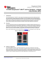
The CC3200 SimpleLink™ Wi-Fi®™ is the industry’s first single-chip microcontroller (MCU) with built-in
Wi-Fi connectivity, created for the Internet of Things (IoT). The CC3200 device is a wireless MCU that
integrates a high-performance ARM Cortex-M4 MCU, allowing customers to develop an entire application
with a single IC. This document introduces the user to the environment setup for the CC3200 SimpleLink
Wi-Fi, along with programming examples from the software development kit (SDK). This document
explains both the platform and the framework available to enable further application development.
1.1
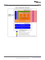
Overview
The Texas Instruments royalty-free CC3200 Embedded Wi-Fi Foundation software development kit is a
complete software platform for developing Wi-Fi applications. It is based on the CC3200, a complete Wi-Fi
SoC (System-on Chip) solution. The CC3200 solution combines a 2.4-GHz Wi-Fi PHY/MAC and TCP/IP
networking engine with a microcontroller, up to 256 kB on-chip RAM (In XCC3200HZ and XCC3101GZ
devices, only 176 kb of RAM is available for applications) and a comprehensive range of peripherals.
Refer to the CC3200 Product Preview and Data Sheet (SWAS032) for more details on the CC3200 chip.
Figure 1. CC3200 Overview of Peripherals
1.2
Software Components
The CC3200 platform includes a user-programmable host, along with a comprehensive networking
solution combined with a Wi-Fi engine. The CC3200 Foundation Software Development Kit provides an
easy-to-use framework, hosted in the on-chip microcontroller, to use the WLAN networking services, and a
comprehensive listing of drivers for peripherals interfaced with the microcontroller. The kit also includes a
reference code for peripheral usage and a few simple applications for networking services.
SWRU369B – June 2014 – Revised March 2015
Submit Documentation Feedback
CC3200 SimpleLink™ Wi-Fi® and IoT Solution, a Single Chip Wireless MCU
Copyright © 2014–2015, Texas Instruments Incorporated
5
Introduction
www.ti.com
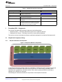
Figure 2 illustrates the various software components and their form in the CC3200 Foundation SDK.
Figure 2. CC3200 Software Components
6
CC3200 SimpleLink™ Wi-Fi® and IoT Solution, a Single Chip Wireless MCU
SWRU369B – June 2014 – Revised March 2015
Submit Documentation Feedback
Copyright © 2014–2015, Texas Instruments Incorporated
Introduction
www.ti.com
1.3
CC3200 LaunchPad Platform
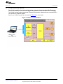
The CC3200 LaunchPad board is the default hardware companion for the foundation SDK. This board
hosts the CC3200 device, with interfaces designed for application software development and debugging.
The CC3200 LaunchPad also supports the TI Booster Pack interface, allowing the user to interface with a
rich repertoire of peripheral systems.
Refer to the CC3200 Launch Pad user manual (SWRU372) for more details
Figure 3. CC3200 LaunchPad Platform
SWRU369B – June 2014 – Revised March 2015
Submit Documentation Feedback
CC3200 SimpleLink™ Wi-Fi® and IoT Solution, a Single Chip Wireless MCU
Copyright © 2014–2015, Texas Instruments Incorporated
7
Foundation SDK – Getting Started
2
www.ti.com
Foundation SDK – Getting Started
This section familiarizes the user with installation process and the directory structure of CC3200
Foundation SDK.
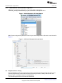
2.1
Installation
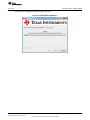
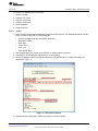
Run the installer by double-clicking the CC3200 SDK installer.
• Read and accept the license agreement to proceed.
Figure 4. CC3200 SDK Installation 1
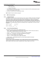
•
Choose an appropriate path to place the package (else default is chosen).
Figure 5. CC3200 SDK Installation 2
8
CC3200 SimpleLink™ Wi-Fi® and IoT Solution, a Single Chip Wireless MCU
SWRU369B – June 2014 – Revised March 2015
Submit Documentation Feedback
Copyright © 2014–2015, Texas Instruments Incorporated
Foundation SDK – Getting Started
www.ti.com
•
Proceed with the installation and click Finish once done.
Figure 6. CC3200 SDK Installation 3
SWRU369B – June 2014 – Revised March 2015
Submit Documentation Feedback
CC3200 SimpleLink™ Wi-Fi® and IoT Solution, a Single Chip Wireless MCU
Copyright © 2014–2015, Texas Instruments Incorporated
9
Foundation SDK – Getting Started
2.2
www.ti.com
Package Components Overview
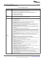
Table 1. Package Contents
Directory Name
docs
•
•
•
•
•
•
•
driverlib
• Contains the peripheral driver library source files.
• The driverlib.a is also provided in the ccs and ewarm directories.
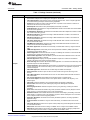
example
10
Information
CC3200 Programmer’s Guide
Documentation for hardware details present in Hardware folder
Documentation for SimpleLink host driver in html format under docs\simplelink_api’ directory
Application notes for all the sample application present in docs\examples directory.
Peripheral driver library user’s guide
Documentation for netapps libraries
Simplelink OTA Extlib API user's guide
• Getting Started in STA Mode: Configures CC3200 in STA mode. It verifies the connection by pinging
the client connected to it.
• Getting Started in AP Mode: Configures CC3200 in AP mode. It verifies the connection by pinging the
client connected to it.
• TCP Socket: Demonstrates the connection scenario and basic TCP functionality.
• UDP Socket: Demonstrates the connection scenario and basic UDP functionality.
• Scan Policy: Demonstrates the scan-policy settings in CC3200.
• SSL: SSL certificates are designed to provide two principles, privacy and authentication. Privacy is
achieved by encryption/decryption and authentication is achieved by signature/verification. The
application demonstrates using a certificate with SSL.
• MAC Filters (NWP Filters): The Rx-Filters feature enables the user to define and manage the Rxfiltering process to reduce the amount of traffic transferred to the host and achieve efficient power
management.
• File_operations: Demonstrates the use of File-System APIs.
• Transceiver_mode: Demonstrates building a proprietary protocol on top of Wi-Fi PHY layer, with the
user given full flexibility to build their own packet. The RX Statistics feature inspects the medium in
terms of congestion, distance, validation of the RF hardware, and help using the RSSI information.
• Provisioning with SmartConfig: Demonstrates the usage of TI's SmartConfig™ Wi-Fi provisioning
technique.
• Provisioning with WPS: Demonstrates the usage of WPS Wi-Fi provisioning with CC31xx/CC32xx.
• Deepsleep Usage: Showcases deepsleep as a power saving tool in a networking context.
• Hib: Showcases the hibernate as a power saving tool in a networking context (in this case an UDP
client).
• Get Time: Connects to an SNTP server and requests for time information.
• Get Weather: Connects to Open Weather Map and requests for weather data.
• Email: Sends emails via SMTP. The email application sends a preconfigured email at the push of a
button or a user-configured email through the CLI.
• XMPP: Demonstrates the connection scenario with an XMPP server.
• Serial Wi-Fi: Serial Wi-Fi is a capability designed to provide easy, self-contained terminal access
behavior, over UART interface.
• Connection Policy: Demonstrates the connection policies in CC3200. The connection policies
determine how the CC3200 connects to AP.
• ENT Wlan: Demonstrates the connection to an enterprise network using the flashed certificate.
Certificate is flashed in SFLASH.
• HTTP server: Demonstrates the HTTP server capability of CC3200.
• mDNS: Demonstrates the usage of mDNS functionality in CC3200. The application showcases both
mDNS advertise and mDNS listen functionality.
• Provisioning AP: Demonstrates the AP provisioning feature.
• Mode config: Used to switch the CC3200 LP from STA to AP and Vice-Versa.
• LED Blink Application: Showcases the usage of GPIO DriverLib APIs. The LEDs connected to the
GPIOs on the LP are used to indicate the GPIO output.
• Timer Demo Application: Showcases the usage of Timer DriverLib APIs. This application uses 16 bit
timers to generate interrupts which in turn toggle the state of the GPIO (driving LEDs).
• Watchdog Demo Application: Showcases the usage of Watchdog timer (WDT) DriverLib APIs. The
objective of this application is to showcase the watchdog timer functionality to reset the system
whenever the system fails.
CC3200 SimpleLink™ Wi-Fi® and IoT Solution, a Single Chip Wireless MCU
SWRU369B – June 2014 – Revised March 2015
Submit Documentation Feedback
Copyright © 2014–2015, Texas Instruments Incorporated
Foundation SDK – Getting Started
www.ti.com
Table 1. Package Contents (continued)
Directory Name
example
Information
• UART Demo Application: Showcases the usage of UART DriverLib APIs. The application
demonstrates a simple echo of anything the user types on the terminal.
• Interrupt Application: Showcases the usage of Interrupt DriverLib APIs. This is a sample application
to showcase interrupt preemption and tail-chaining capabilities.
• I2C Demo: Showcases the usage of I2C DriverLib APIs. It provides a user interface to read-from or
write-to the I2C devices on the Launch-Pad.
• MCU Sleep-DS: Exercises the Sleep and Deepsleep functionality of the MCU.
• uDMA Application: Showcases the usage of UDMA DriverLib APIs. Various DMA mode functionalities
are shown in this application.
• FreeRTOS Demo Application: Showcases the FreeRTOS features like multiple task creation and inter
task communication using queues.
• AES Demo Application: Showcases the usage of AES Driverlib APIs. Provides a user interface to
exercise various AES modes.
• DES Demo Application: Showcases the usage of DES Driverlib APIs. Provides a user interface to
exercise various DES modes.
• CRC Demo Application: Showcases the usage of CRC Driverlib APIs. Provides a user interface to
exercise various CRC modes.
• SHA-MD5 Demo Application: Showcases the usage of SHA-MD5 Driverlib APIs. Provides a user
interface to exercise various SHA-MD5 modes.
• ADC Demo Application: Showcases the functionality of CC3200 ADC module by using the Driverlib
APIs.
• PWM Demo Application: Showcases general 16-bit pulse-width modulation (PWM) mode feature
supported by purpose timers (GPTs).
• SD Host Application: Showcases the basic use case of initializing the controller to communicate with
the attached card, reading and writing SD card block.
• SD Host FatFS Application: Uses the FatFS to provide the block level read/write access to SD card,
using the SD Host controller on CC3200.
• SPI Demo Application: Displays the required initialization sequence to enable the CC3200 SPI
module in full duplex 4-wire master and slave mode(s).
• Wi-Fi Audio App: Demonstrates ‘Bi-directional Audio Application’ on a CC3200 LaunchPad setup. This
application requires the audio boosterpack.
• Camera Application: Demonstrates the camera feature on CC3200 device. User can invoke the image
capture command on the web browser hosting on the CC3200 device. This application requires the
camera boosterpack.
• UART DMA Application: Showcases use of UART along with uDMA and interrupts.
• Antenna Selection: Gives the option to select an antenna with more signal for APs using a webbrowser.
• Out of Box Application: Demonstrates how the user can view different demo and SDK web links on
their web-browser.
• Peer to Peer Application: Demonstrates the Wi-Fi direct feature on CC3200 device.
• Timer Count Capture: Showcases Timer's count capture feature to measure the frequency of an
external signal.
• Idle Profile: Exercises hibernation using Power Management Framework (middleware).
• Sensor Profile: Exercises low power modes (lpds) using Power Management Framework
(middleware).
• Watchdog System Demo: Illustrates full system recovery using watchdog, including the network
subsystem.
• TFTP Client: Demonstrates file transfer using TFTP (Trivial File Transfer Protocol). Requires a TFTP
Server running on a connected device such as a PC or Smartphone.
• WebSocket Camera: Demonstrates Websocket HTTP Server functionality by transmitting continuous
JPEG frames to a websocket client. This application requires a camera boosterpack and a connected
PC or smartphone with a browser supporting HTML 5.
• Application Bootloader: Showcases the secondary bootloader operations, to manage updates to
application image.
• HTTP Client Demo: Illustrates the usage of HTTP Client library, to enable the device as an HTTP
client.
• Idle Profile (Non OS): Exercises the low power modes (LPDS) using Power Management Framework
in a Non-OS environment.
• MQTT Client: Showcases the device acting as a MQTT client in a fully-functional MQTT network.
• MQTT Server: Showcases the device acting as an MQTT server capable of managing multiple local
clients, and allowing the local clients to communicate with remote MQTT clients.
SWRU369B – June 2014 – Revised March 2015
Submit Documentation Feedback
CC3200 SimpleLink™ Wi-Fi® and IoT Solution, a Single Chip Wireless MCU
Copyright © 2014–2015, Texas Instruments Incorporated
11
Foundation SDK – Getting Started
www.ti.com
Table 1. Package Contents (continued)
Directory Name
2.3
Information
example
• OTA Update: Illustrates Over-The-Air (OTA) update of service pack, user application, and user files.
• Dynamic Library Loader: Exercises an approach to enable dynamic loading of an application-binary
from non-volatile memory while the program is being executed.
Inc
• Contains the register definition header files.
Oslib
• Contains the interface file to configure Free-RTOS or TI-RTOS.
Middleware
• Contains power management framework to provide a simple infrastructure for developers to create a
power aware solution.
NetApps
•
•
•
•
•
•
Simplelink
• Contains 'SimpleLink Host Driver' code.
Simplelink_extlib
• Contains the OTA (Over the Air) library
Documents
• Documentation for netapps libraries
Third_
party
FatFS
• Contains the FatFS source files.
FreeRT
OS
• Contains the FreeRTOS source files. Current SDK supports FreeRTOS v8.0.1.
http: Contains the HTTP (Hyper Text Transfer Protocol) client and server library
smtp: Contains the SMTP (Simple Mail Transfer Protocol) client library
tftp: Contains the TFTP (Trivial File Transfer Protocol) client library
xmpp: Contains the XMPP (Extensive Messaging and Presence Protocol) client library
json: Contains JSON parser library
mqtt: Contains the MQTT (Message Queue Telemetry Transport) client and server library
Ti_rtos
• Contains the Ti RTOS config file and CCS, IAR , GCC project to support TI-RTOS with all three IDEs.
Current SDK supports TI-RTOS v2.1.0.03.
Tools
•
•
•
•
ccs_patch – Contains the files required for CCS-FTDI-LP connection.
iar_patch – Contains the files required for IAR-FTDI-LP connection.
ftdi - Contains FTDI PC driver.
gcc_scripts - Contains the scripts to use GCC and openocd with CC3200.
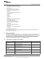
Prerequisite: Tools to be Installed
Table 2. CC3200 Prerequisite
Tools
Remarks
Location
IAR version 7.20 onwards must be installed. After the
installation, follow the tools\iar_patch\readme.txt to be
able to debug over FTDI.
Installation:
http://www.iar.com/Products/IAREmbedded-Workbench/ARM/
CCS
CCS 6.0.1 version and 'TI v5.1.6' compiler version.
After the installation, follow the
tools\ccs_patch\readme.txt to be able to debug over
FTDI.
Installation:
http://www.ti.com/tool/ccstudio
CC3200 Support package in
CCSv6.0
Though CCS 6.0.1 provides an option to install this
add-on during installation, the user must check and
install if a newer version is available.
Refer to Section 5.3.2.1
To enable CC3200 SDK development on Linux
environment.
Refer to Section 5.3.3
Development Environment
IAR
Or/and
Or/and
GCC
CC32xx PinMux Utility
CC32xx PinMux Utility.exe
12
Utility to assign a desired personality to the general
Installation:
purpose pins available at the CC3200 device boundary. http://processors.wiki.ti.com/index.php/TI_
PinMux_Tool or refer to Section 5.3.2.2
CC3200 SimpleLink™ Wi-Fi® and IoT Solution, a Single Chip Wireless MCU
SWRU369B – June 2014 – Revised March 2015
Submit Documentation Feedback
Copyright © 2014–2015, Texas Instruments Incorporated
Foundation SDK – Components
www.ti.com
Table 2. CC3200 Prerequisite (continued)
Tools
Remarks
Location
Tool to download firmware, application image, and
certificate to CC3200 device.
http://www.ti.com/tool/uniflash
CC32xx Programmer Utility
Uniflash
Support Tools
3
HyperTerminal or Teraterm
Serial communication tool to communicate over the
UART with the CC3200 device.
Iperf
A useful tool for measuring TCP and UDP bandwidth
performance.
FTDI Driver
FTDI Windows drivers need to be installed for a
successful connection to the CC3200 LP over USB.
This FTDI connection can be used for debugging over
JTAG/SWD and communicating over UART.
tools\ftdi
Foundation SDK – Components
The CC3200 Foundation SDK package includes two main building blocks:
• SimpleLink Library – This library hosts APIs that serve the connectivity features.
• Peripheral Driver Library – This library hosts APIs to access MCU peripherals.
This section also lists the sample and reference applications packaged in the Software Development Kit.
3.1
3.1.1
SimpleLink Component Library
SimpleLink Modular Decomposition
Figure 7. SimpleLink Modular Composition
TI SimpleLink Framework provides a wide set of capabilities, including basic device management through
wireless network configuration, BSD socket services, and more. For better design granularity, these
capabilities are segregated into individual modules. Each module represents different functionality or
capability of the SimpleLink Framework.
The following list enumerates the different components in the SimpleLink Framework:
SWRU369B – June 2014 – Revised March 2015
Submit Documentation Feedback
CC3200 SimpleLink™ Wi-Fi® and IoT Solution, a Single Chip Wireless MCU
Copyright © 2014–2015, Texas Instruments Incorporated
13
Foundation SDK – Components
Components
3.1.2
www.ti.com
Functionality
device
• Initializes the host
• Controls the communication with the Network Processor
wlan
•
•
•
•
socket
• UDP/TCP Client Socket
• UDP/TCP Server Socket
• UDP/TCP Rx/Tx
netapp
• DNS Resolution
• Ping remote device
• Address Resolution Protocol
netcfg
• IP/MAC address configuration
fs
• File system Read/Write
Connection to the access point
Scan access points
Add/Remove access point profiles
WLAN Security
Using the TI SimpleLink Framework
TI SimpleLink Framework provides a rich, yet simple set of APIs. For detailed information on the APIs and
their usage, refer to the document docs\simplelink_api\programmers_guide.html available in the SDK.
TI SimpleLink Framework has a ready-to-use port available in the CC3200 Foundation SDK. The source
code is also shared if further customization is desired by the developer. The following note describes
simple possible customizations and the associated procedure.
Note: All modifications and adjustments to the driver should be made in the user.h header file only, to
ensure a smooth transaction to future versions of the driver.
Modify user.h file – Modify the user.h file that includes the default configurations and adjustments.
Select the capabilities set required for your application – TI has focused on building a set of
predefined capability sets that fit most target applications. TI recommends trying and choosing one of
these predefined capabilities sets before building a customized set. Once a compatible set is found, skip
the rest of this step. The available sets are:
• # SL_TINY – Compatible with platforms with very limited resources. Provides the best-in-class footprint
in terms of code and data consumption.
• # SL_SMALL – Compatible with most common networking applications. Provides the most common
APIs with a balance between code size, data size, functionality, and performance.
• # SL_FULL – Provides access to all SimpleLink functionalities.
Memory management model – The SimpleLink driver supports two memory models:
• Static (default)
• Dynamic
The CC3200 default configuration is Static. In the dynamic model, the configuration uses the malloc and
free, as defined by the operating system. If the user wishes to define their own memory management, they
can define these interfaces.
Asynchronous event handlers routines – The SimpleLink device generates asynchronous events in
several situations. These asynchronous events could be masked. Provide handler routines to catch these
events. If a handler routine was not provided and the event is received, the driver will drop this event
without any indication of a drop.
Interface communication driver – The CC3200 host driver implements SPI communication interface.
The interface for this communication channel includes four simple access functions:
1. open
2. close
3. read
14
CC3200 SimpleLink™ Wi-Fi® and IoT Solution, a Single Chip Wireless MCU
SWRU369B – June 2014 – Revised March 2015
Submit Documentation Feedback
Copyright © 2014–2015, Texas Instruments Incorporated
Foundation SDK – Components
www.ti.com
4. write
The CC3200, SPI implementation uses DMA to increase the utilization of the communication channel.
OS adaptation – The SimpleLink driver can run on two kinds of platforms:
• Non-OS / Single-Threaded (default)
• Multi-Threaded
The CC3200 SimpleLink host driver is ported on both Non-OS and Multi-Threaded OS environments. The
host driver is made OS-independent by implementing an OS Abstraction layer. Reference implementation
for OS Abstraction is available for FreeRTOS and TI-RTOS.
To work in a multi-threaded environment under a different operating system, provide some basic
adaptation routines to allow the driver to protect access to resources for different threads (locking object)
and to allow synchronization between threads (sync objects). In addition, the driver support runs without a
dedicated thread allocated solely to the SimpleLink driver. To work in this mode, supply a spawn method
that enables functions to run on a temporary context.
SWRU369B – June 2014 – Revised March 2015
Submit Documentation Feedback
CC3200 SimpleLink™ Wi-Fi® and IoT Solution, a Single Chip Wireless MCU
Copyright © 2014–2015, Texas Instruments Incorporated
15
Foundation SDK – Components
3.1.3
www.ti.com
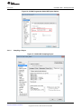
Switch Between OS and NON-OS Configuration
IAR: Choose configuration options from menu Project->Edit configurations>OS/NON_OS/PM_Framework/NON_OS_PM, as indicated in the snapshot below:
Figure 8. CC3200 SimpleLink IAR Config Switch
CCS: Choose configuration options from menu Project->Build Configurations->Set active or as indicated in
Figure 9:
Figure 9. CC3200 CCS SimpleLink Config Switch
3.2
Peripheral Driver Library
The CC3200 ROM contains the peripheral driver library (DriverLib) and the boot loader. DriverLib can be
utilized by applications to reduce their flash footprint, allowing the flash (or RAM) to be used for other
purposes (such as additional features in the application).
The Driverlib supports APIs for the modules listed below:
16
CC3200 SimpleLink™ Wi-Fi® and IoT Solution, a Single Chip Wireless MCU
SWRU369B – June 2014 – Revised March 2015
Submit Documentation Feedback
Copyright © 2014–2015, Texas Instruments Incorporated
Foundation SDK – Components
www.ti.com
•
•
•
•
•
•
•
•
•
•
•
•
•
•
•
•
•
•
•
•
•
•
ADC_Analog_to_Digital_Converter_api
AES_Advanced_Encryption_Standard_api
Camera_api
CRC_Cyclic_Redundancy_Check_api
DES_Data_Encryption_Standard_api
Flash_api
GPIO_General_Purpose_InputOutput_api
HwSpinLock_api
I2C_api
I2S_api
Interrupt_api
Pin_api
PRCM_Power_Reset_Clock_Module_api
Secure_Digital_Host_api
SHA_Secure_Hash_Algorithm_api
SPI_Serial_Peripheral_Interface_api
Systick_api
GPT_General_Purpose_Timer_api
UART_api
UDMA_Micro_Direct_Memory_Access_api
Utils_api
WDT_Watchdog_Timer_api
For detailed information on the APIs and their usage, refer to the document docs\CC3200 Peripheral
Driver Library User's Guide.chm.
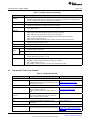
3.3
Reference Applications
The reference applications available as a part of the SDK package are example implementations, which
demonstrate key features and peripherals supported by the subsystem built around the CC3200 device on
the LaunchPad. A brief description of the reference applications are tabulated below. Refer to the
readme.txt present in the individual folders for further information. All examples are broadly divided into
two types: the network reference and the MCU-only reference examples.
3.3.1
Network Reference Examples for the CC3200 LP
Application / Demo
Description
Peripheral/Feature exercised
Getting started with wLAN
Station
This application showcases the device's capability as a station
in a typical networking system.
Networking (STA mode)
Getting started with wLAN
AP
This application showcases the device's capability as an AP in
a typical networking system.
Networking (AP mode)
TCP Socket Application
This application showcases the device's communication over
network using TCP protocols.
Networking (Basics)
WLAN Scan Policies
Application
This application sets scan policy and enables the scan in the
device.
Networking (Scan policies)
UDP Socket Application
This application showcases the device's communication over
network using TCP protocols.
Networking (Basics)
SSL Demo Application
This application showcases SSL implementation on CC3200
device.
Networking (SSL)
NWP Filter Application
This application showcases the Rx-Filter feature on CC3200
device.
Networking (MAC Filters)
SWRU369B – June 2014 – Revised March 2015
Submit Documentation Feedback
CC3200 SimpleLink™ Wi-Fi® and IoT Solution, a Single Chip Wireless MCU
Copyright © 2014–2015, Texas Instruments Incorporated
17
Foundation SDK – Components
18
www.ti.com
Application / Demo
Description
Peripheral/Feature exercised
File Operations Application
This application showcases the file operation on the serial
flash of the device.
SFlash (File operations)
Transceiver mode
Application
The RX Statistics feature inspects the medium in terms of
congestion and distance, validates he RF hardware, and help
using the RSSI information.
Networking (Raw sockets),
GPIO, UART, Timer
Provisioning - Smart Config
Application
The application demonstrates how to associate/connect
CC31xx/CC32xx to any access point.
Networking (Provisioning)
Deep-Sleep Application
This application showcases the deepsleep as a power saving
tool in a networking context of CC3200 device.
Networking, Low power modes
(DeepSleep), UART, GPIO,
Timer
Hibernate Application
This application showcases hibernate as a power saving tool
in a networking context (in this case a UDP client).
Networking, Low power modes
(HIB), UART, GPIO, Timer
Info Center-Get Time
Application
The application connects to an SNTP server and requests for
time information.
Networking (Internet)
Info Center-Get Weather
Application
The application connects to ‘Open Weather Map’ and requests Networking (Internet)
for weather data.
Email Application
The email application on the CC3200 sends emails via SMTP.
Networking, GPIO, UART, Timer
XMPP Reference Application
The application demonstrates the connection scenario with an
XMPP server.
Networking (Internet)
Provisioning-WPS
Application
This application demonstrates how to use WPS Wi-Fi
provisioning with CC3200.
Networking (Provisioning), GPIO
Mode-Configuration
Application
This application configures the device either to a station or an
AP mode.
Networking (STA/AP mode)
Serial Wi-Fi Application
Serial Wi-Fi is a capability designed to provide easy, selfcontained terminal access behavior over a UART interface.
Networking
Connection Policy
Application
The application demonstrates the connection policies in
CC3200. The connection policies determine how the CC3200
is connected to AP.
Networking(STA Mode)
ENT WLAN Application
The example demonstrates the connection to an enterprise
network using the flashed certificate. Certificate is flashed in
SFLASH.
Networking(STA mode)
HTTP Server Application
The application demonstrates the Http server capability of
CC3200.
Networking(STA Mode)
mDNS Application
The application demonstrates the usage of mDNS functionality Networking(STA Mode) , UART
in CC3200. The application showcases both “mDNS advertise”
and “mDNS listen” functionality.
Provisioning-AP Application
This application demonstrates the AP provisioning feature.
CC3200 AP Provisioning is method by which user can
configure the AP information on the CC3200 device from a
Browser.
Networking(AP Mode)
Out of Box Application
This application demonstrates the how the user can view
different demo and SDK web links on a web-browser.
Networking(AP/STA mode), I2C,
GPIO
Wi-Fi Audio Application
This example demonstrates ‘Bi-directional Audio Application’
on a CC3200 LaunchPad setup. The system is comprised of
two LPs (in STA mode). Audio is streamed from one LP and
rendered on another LP over Wi-Fi. This application requires
the audio boosterpack.
Networking(STA/AP mode)
Antenna Selection
Application
This example allows the user to select the antenna with the
highest signal for APs using a web-browser.
Networking(AP mode)
Camera Application
This example demonstrates the camera feature on CC3200
device. This application requires the camera boosterpack.
Networking(AP mode)
Peer to Peer Application
This example demonstrates the Wi-Fi direct feature on
CC3200 device.
Networking(p2p mode)
Idle Profile
This application exercises hibernation using Power
Management Framework (middleware).
Networking(STA Mode)
Sensor Profile
This application exercises low power modes (lpds) using
Power Management Framework (middleware).
Networking(STA Mode)
File Download Application
This application demonstrates file downloading from the web
server and stores it to the device memory feature on the
CC3200 device.
Networking (STA Mode)
CC3200 SimpleLink™ Wi-Fi® and IoT Solution, a Single Chip Wireless MCU
SWRU369B – June 2014 – Revised March 2015
Submit Documentation Feedback
Copyright © 2014–2015, Texas Instruments Incorporated
Foundation SDK – Components
www.ti.com
3.3.2
Application / Demo
Description
Peripheral/Feature exercised
Watchdog System Demo
This application illustrates a full system recovery using
watchdog, including the network subsystem.
Networking (STA Mode)
TFTP Client
This application demonstrates file transfer using TFTP (Trivial
File Transfer Protocol). Requires a TFTP Server running on a
connected device such as PC or smartphone.
Networking (STA Mode)
WebSocket Camera
This application demonstrates Websocket HTTP Server
functionality by transmitting continuous JPEG frames to a
websocket client. This application requires camera
boosterpack and a connected PC or smartphone with a
browser supporting HTML 5.
Networking (AP Mode)
HTTP Client Demo
This application illustrates the usage of HTTP Client library to
enable the device as an HTTP client.
Networking (STA mode)
Idle Profile (Non OS)
This application exercises the low power modes (LPDS) using
Power Management Framework in a Non-OS environment.
Networking (STA mode)
MQTT Client
This application showcases the device acting as a MQTT
client in a fully-functional MQTT network.
Networking (STA mode)
MQTT Server
This application showcases the device acting as an MQTT
Networking (STA mode)
server capable of managing multiple local clients, and allowing
the local clients to communicate with remote MQTT clients.
OTA Update
This application illustrates Over-The-Air (OTA) update of
service pack, user application and user files.
Networking (STA mode)
MCU Only Reference Examples for the CC3200 LP
Application / Demo
Description
Peripheral/Feature
exercised
LED Blink Application
This application showcases the blinking feature of available LEDs
connected over GPIO on LP.
GPIO
Timer Demo Application
This application showcases the usage of 16 bit timers to generate interrupts Timer, GPIO, UART
which toggle the state of the GPIO.
Watchdog Demo
Application
This application showcases the watchdog timer functionality to reset the
system whenever the system fails.
WDT, GPIO, UART
UART Demo Application
This application showcases the use of UART.
UART
Interrupt Demo Application
A sample application showcasing interrupt preemption and tail-chaining
capabilities.
NVIC, UART
I2C Demo
A sample application showing i2c read/write/read from features on CC3200
device.
I2C, UART
MCU Sleep-DeepSleep
This application exercises the Sleep and DeepSleep functionality of the
MCU.
Low power modes
(Sleep, DeepSleep),
UART
uDMA Application
This application showcases different DMA modes of transfer.
uDMA, UART
Autorun non-OS
Application
This application showcases the basic packet send and receive functionality
of CC3200 in a non OS environment.
0.2
AES Demo Application
This application showcases the AES Encryption feature on CC3200 device.
Crypto, UART
DES Demo Application
This application showcases the DES Encryption feature on CC3200 device.
Crypto, UART
CRC Demo Application
This application showcases the CRC feature on CC3200 device.
Crypto, UART
FeeRTOS Demo Application This application showcases the FreeRTOS features like Multiple task
creation, Inter task communication using queues.
UART
SHA-MD5 Demo
Application
This application showcases the SHA-MD5 Hash Algorithm on CC3200
device
Crypto, UART
ADC Demo Application
This application showcases the functionality of CC3200 ADC module by
using the Driverlib APIs.
ADC, UART
PWM Demo Application
This application showcases the PWM mode of CC3200 GPTs. The general
purpose timers (GPTs) support a 16-bit pulse-width modulation (PWM)
mode with software-programmable output inversion of the PWM signal.
Timer, GPIO
SWRU369B – June 2014 – Revised March 2015
Submit Documentation Feedback
CC3200 SimpleLink™ Wi-Fi® and IoT Solution, a Single Chip Wireless MCU
Copyright © 2014–2015, Texas Instruments Incorporated
19
Foundation SDK – Components
3.4
www.ti.com
Application / Demo
Description
Peripheral/Feature
exercised
SDHost Demo Application
This application showcases the functionality of SDHost module in CC3200.
The Secure Digital Host (SD Host)controller on CC3200 provides an
interface to standard SD memory cards in 1-bit transfer mode and handles
the SD protocol and data packing at transmission level with minimum CPU
intervention.
UART, SDHOST
SDHost FatFS Demo
Application
This application uses the FatFS to provide the block level read/write access
to SD card, using the SD Host controller on CC3200.
UART, SDHOST
SPI Demo Application
The demo application shows the required initialization sequence to enable
the CC3200 SPI module in full duplex 4-wire master and slave mode(s).
UART, SPI
UART dma Application
The demo application showcases use of UART along with uDMA and
interrupts.
UART, DMA
Timer Count Capture
Application
This application showcases Timer's count capture feature to measure
frequency of an external signal.
TIMER
Application Bootloader
This application showcases the secondary bootloader operations to manage SPI for serial flash
updates to application image.
access
Dynamic Library Loader
This application exercises an approach to enable dynamic loading of an
application-binary from non-volatile memory while the program is being
executed.
CC3200 PinMux Utility
The CC3200 pinmux utility provides a convenient interface to select the personality of the general purpose
pins available at the CC3200 device boundary. The tool generates the source files based on the
information selected using the tool, and can be directly included in the project. Refer to the CC3200
PinMux tool wiki page for further details.
Refer to Section 5.3.2.2 for getting the new TI-Pinmux Tool.
20
CC3200 SimpleLink™ Wi-Fi® and IoT Solution, a Single Chip Wireless MCU
SWRU369B – June 2014 – Revised March 2015
Submit Documentation Feedback
Copyright © 2014–2015, Texas Instruments Incorporated
Getting Started with CC3200 Launchpad
www.ti.com
4
Getting Started with CC3200 Launchpad
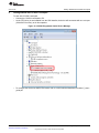
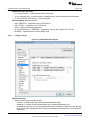
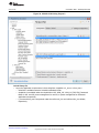
To start with CC3200 Launchpad:
• Connect the CC3200 Launchpad to PC.
• As the FTDI driver is auto-installed from the SDK installer, the device will enumerate with one com port
(CC3200LP Dual Port), as in this snapshot:
Figure 10. CC3200 Programmer Guide Device Manager
•
To configure the device into SWD/JTAG mode, refer to cc3200-sdk\docs\hardware\CC3200-LP_User's
guide.pdf.
SWRU369B – June 2014 – Revised March 2015
Submit Documentation Feedback
CC3200 SimpleLink™ Wi-Fi® and IoT Solution, a Single Chip Wireless MCU
Copyright © 2014–2015, Texas Instruments Incorporated
21
Foundation SDK – Development Flow
5
www.ti.com
Foundation SDK – Development Flow
This section familiarizes the developer with the typical development flow using the building blocks hosted
in Foundation SDK, and emphasizes more of the network aspects of the CC3200. For this purpose, a
suite of Getting Started applications are presented in the SDK. Start with a comprehensive description of
these applications, build and execute procedure with the IDEs, and finally burn the application image in
the non-volatile storage.
The SDK contains five simple network applications to demonstrate the connection and packet-handling
functionality. These applications use the SimpleLink APIs to demonstrate the functionality. The source in
these applications is modular, and can be referred or re-used by the developer.
5.1
Application
Description
1.
Getting started with WLAN Station
Reference application to use the CC3200 in STA mode
2.
Getting started with WLAN AP
Reference application to use the CC3200 in AP(Access Point) mode
3.
TCP Socket Application
Reference application showcasing the TCP server and client functionality
4.
UDP Socket Application
Reference application showcasing the UDP server and client functionality
5.
Raw Socket (Transceiver Mode
Application)
Reference application showcasing the Raw socket functionality
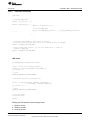
Simple Networking Applications
Any SimpleLink API (sl_* ) must be invoked only after the sl_Start() API has completed. This function
starts the SimpleLink (Networking) device. This function also initializes the communication interface.
5.1.1
Getting Started with WLAN Station
5.1.1.1
Application Details
This application shows the CC3200 device as a station in a simple network. Developers and users can
refer the function or re-use them while writing a new application. The device connects to an AP (access
point), with AP configurations stored in the form of macros in the application. If the connection is
successful, it will try to get the IP address of “www.ti.com” and then ping to the IP address. Zero is the
expected return value. A different return code indicates that the internet connection is not available or that
the ping was not successful. The application uses LEDs to indicate the test results; RED indicates an AP
connection, GREEN indicates ping to AP, and ORANGE indicates a ping to www.ti.com.
Security Macros
#define SSID_NAME "cc3200demo"
#define SECURITY_TYPE SL_SEC_TYPE_OPEN
#define SECURITY_KEY ""
5.1.1.2
Source Files Briefly Explained
The application source can be found in example\getting_started_with_wlan_station.
• main.c – Main file creates the SimpleLink task which handles most of the network related operations,
while a WlanStationMode task makes calls to the network-related APIs of the SimpleLink library.
• startup_ewarm.c – IAR workbench-specific vector table implementation for interrupts
• pinmux.c – Contains the configurations to mux the device pins
• gpio_if.c – Common interface file for LED use
• uart_if.c – Common interface file for UART prints
Supporting folders/files
22
CC3200 SimpleLink™ Wi-Fi® and IoT Solution, a Single Chip Wireless MCU
SWRU369B – June 2014 – Revised March 2015
Submit Documentation Feedback
Copyright © 2014–2015, Texas Instruments Incorporated
Foundation SDK – Development Flow
www.ti.com
The ewarm folder contains the IAR workspace. The ccs folder contains the CCS Project, the driverlib
folder contains all the driver files, the oslib folder contains the project to build the TI-RTOS/Free-RTOS
library, and the simplelink folder contains SimpleLink host files.
5.1.1.3
Code Flow Connection
void WlanStationMode( void *pvParameters )
{
...
//Start the SimpleLink
lRetVal = sl_Start(0, 0, 0);
...
// Connecting to WLAN AP
lRetVal = WlanConnect();
/* ...
lRetVal = sl_WlanConnect(...);
...
// Wait for WLAN Event
while((!IS_CONNECTED(g_ulStatus)) ||
(!IS_IP_ACQUIRED(g_ulStatus))) { ... }
...
*/
...
// Checking the Lan connection by pinging to AP gateway
lRetVal = CheckLanConnection(); /* ...
// Check for LAN connection
lRetVal = sl_NetAppPingStart(...);
...
// wait for Ping report event
while(!IS_PING_DONE(g_ulStatus)) { ... }
*/
...
// Checking the internet connection by pinging to external host
lRetVal = CheckInternetConnection(); /* ...
// Get external host IP address
lRetVal = sl_NetAppDnsGetHostByName(...);
...
// Try to ping HOST_NAME
lRetVal = sl_NetAppPingStart(...);
...
// Wait for Ping done event
while(!IS_PING_DONE(g_ulStatus)) { ... }
*/
SWRU369B – June 2014 – Revised March 2015
Submit Documentation Feedback
CC3200 SimpleLink™ Wi-Fi® and IoT Solution, a Single Chip Wireless MCU
Copyright © 2014–2015, Texas Instruments Incorporated
23
Foundation SDK – Development Flow
www.ti.com
...
}
Using the CC3200 as a STA is a three step process.
1. Start the SimpleLink by calling the sl_Start( ) API.
2. Connect to the AP by calling the sl_WlanConnect( ) API.
3. Ping to the AP and external host by calling the sl_NetAppPingStart() API.
Refer to the main.c file of the reference application for more details.
5.1.1.4
1.
2.
3.
Usage
Run the application (getting_started_with_wlan_sta) from IAR/CCS, or flash the bin file to the device.
The device switches to STA mode if it is in the other mode.
The device tries to connect to open a pre-defined AP (cc3200demo). The red LED glows upon a
successful connection.
4. The device pings to AP. If the ping is successful, the green LED glows.
5. The device checks for an internet connection by pinging to www.ti.com. If this ping is successful, the
orange LED glows.
5.1.2
Getting Started with WLAN AP
5.1.2.1
Application Details
This application aims to exhibit the CC3200 device as an AP. Developers and users can refer or re-use
the function while writing a new application. The device comes up as an AP (access point), then waits for
a station to connect to it. If the connection is successful, it pings to that station. Zero is the expected return
value. A different return code indicates that the ping to the station was unsuccessful.
5.1.2.2
•
•
•
•
Source Files Briefly Explained
main.c – Main file creates the SimpleLink task which handles most of the network related operations,
while a WlanStationMode task makes calls to the network-related APIs of the SimpleLink library.
startup_ewarm.c – IAR workbench-specific vector table implementation for interrupts
pinmux.c – Contains the configurations to mux the device pins
uart_if.c – Common interface file for UART prints
Supporting folders/files
The ewarm folder contains IAR workspace. The ccs folder contains CCS Project, the driverlib folder
contains all the driver files, the oslib folder contains the project to build the TI-RTOS/Free-RTOS library
and the simplelink folder contains SimpleLink Host Files
24
CC3200 SimpleLink™ Wi-Fi® and IoT Solution, a Single Chip Wireless MCU
SWRU369B – June 2014 – Revised March 2015
Submit Documentation Feedback
Copyright © 2014–2015, Texas Instruments Incorporated
Foundation SDK – Development Flow
www.ti.com
5.1.2.3
Code Flow Connection
void WlanAPMode( void *pvParameters )
{
...
lRetVal = sl_Start(NULL,NULL,NULL);
...
// Configure the networking mode ssid name (for AP mode)
ConfigureMode(lRetVal) ;
/* ...
lRetVal = sl_WlanSetMode(ROLE_AP);
// set SSID name
lRetVal = sl_WlanSet( ... );
...
*/
while(!IS_IP_ACQUIRED(g_ulStatus))
{
//looping till ip is acquired
}
// get network configuration
lRetVal = sl_NetCfgGet(SL_IPV4_STA_P2P_CL_GET_INFO,&ucDHCP,&len, (unsigned char *)&ipV4);
while(!IS_IP_LEASED(g_ulStatus))
{
//wating for the STA to connect
}
// Ping to connected client
iTestResult = PingTest(ulIpAddr);
...
}
Using the CC3200 as an AP is a two step process:
(a) Start the SimpleLink by calling the sl_Start() API.
(b) Wait until the device gets an IP address.
After the device comes up in AP mode, follow these steps to ensure the device can act as an AP:
1. Wait for a station to connect to the device (the user must connect a machine to the device).
2. Ping the station (machine)
Refer to the main.c file of the reference application for more details.
NOTE: If the device is not able to ping to the connected machine, try disabling the antivirus on the
machine.
5.1.2.4
1.
2.
3.
Usage
Run the application (getting_started_with_wlan_ap) from IAR/CCS or flash to the device.
Application will switch to AP mode if it is not in AP mode.
After the client connects to the device, the device (AP) pings the client and prints the result over
UART.
4. All results can be viewed on the terminal screen.
5. Observe the execution flow to understand the result.
SWRU369B – June 2014 – Revised March 2015
Submit Documentation Feedback
CC3200 SimpleLink™ Wi-Fi® and IoT Solution, a Single Chip Wireless MCU
Copyright © 2014–2015, Texas Instruments Incorporated
25
Foundation SDK – Development Flow
5.1.3
www.ti.com
TCP Socket Application
5.1.3.1
Application Details
This application illustrates how to use the device as a client or server for TCP communication. Developers
and users can refer or re-use the function while writing new applications. The device connects to an AP
(access point), with the SSID for AP stored as a macro in the application. Initially, the application
implements a TCP client and sends 1000 TCP packets to a socket address, port number, and IP address
specified as macros. Zero is the expected return code. A different return code indicates that a socket error
has occurred. The default setting is defined as in the following macros, which can be changed either in the
source code or at runtime.
#define
#define
#define
#define
5.1.3.2
•
•
•
•
•
•
SSID_NAME
"cc3200demo"
IP_ADDR
0xc0a8006E
PORT_NUM
5001
TCP_PACKET_COUNT
1000
Source Files Briefly Explained
main.c – Main file calls SimpleLink APIs to connect to the network, creates a socket, and uses it to
communicate over TCP by acting as a TCP client or server.
pinmux.c – Pinmux file to mux the device to configure a UART peripheral.
startup_ccs.c – CCS-specific vector table implementation for interrupts
uart_if.c – Common interface file for UART prints
udma_if.c – Common interface file for uDMA functionalities
startup_ewarm.c – IAR workbench-specific vector table implementation for interrupts
Supporting folders/files
The ewarm folder contains IAR workspace. The ccs folder contains CCS Project, the driverlib folder
contains all the driver files, and the simplelink folder contains Simple Link Host Files
5.1.3.3
Code Flow Connection
void main()
{
...
// Starting SimpleLink
lRetVal = sl_Start(0, 0, 0);
...
lRetVal = WlanConnect(); /* ...
lRetVal = sl_WlanConnect(...);
...
// Wait for WLAN Event
while((!IS_CONNECTED(g_ulStatus)) ||
(!IS_IP_ACQUIRED(g_ulStatus)))
{ ... }
...
*/
...
/* following calls depend on user's input at runtime */
.
// Before proceeding, please make sure to have a server waiting on PORT_NUM
lRetVal = BsdTcpClient(PORT_NUM);
// After calling this function, you can start sending data to CC3100 IP
// address on PORT_NUM
lRetVal = BsdTcpServer(PORT_NUM);
...
}
26
CC3200 SimpleLink™ Wi-Fi® and IoT Solution, a Single Chip Wireless MCU
SWRU369B – June 2014 – Revised March 2015
Submit Documentation Feedback
Copyright © 2014–2015, Texas Instruments Incorporated
Foundation SDK – Development Flow
www.ti.com
TCP Client
int BsdTcpClient(unsigned short usPort)
{
...
//Open a socket with standard parameters
iSockID = sl_Socket(SL_AF_INET,SL_SOCK_STREAM, 0);
if( iSockID < 0 )
{
// error
ASSERT_ON_ERROR(TCP_CLIENT_FAILED);
}
//Connect to the server IP and port number
iStatus = sl_Connect(iSockID, ( SlSockAddr_t *)&sAddr, iAddrSize);
if( iStatus < 0 )
{
// error
ASSERT_ON_ERROR(TCP_CLIENT_FAILED);
}
...
//Send packet using the sl_Send API call
iStatus = sl_Send(iSockID, g_cBsdBuf, sTestBufLen, 0 );
if( iStatus < 0 )
{
// error
ASSERT_ON_ERROR(TCP_CLIENT_FAILED);
}
...
//Close the socket
sl_Close(iSockID);
SUCCESS
}
Sending the TCP packets is a four step process.
1. Open the socket
2. Connect to the server
3. Send the packets
4. Close the socket
SWRU369B – June 2014 – Revised March 2015
Submit Documentation Feedback
CC3200 SimpleLink™ Wi-Fi® and IoT Solution, a Single Chip Wireless MCU
Copyright © 2014–2015, Texas Instruments Incorporated
27
Foundation SDK – Development Flow
www.ti.com
TCP Server
int BsdTcpServer(unsigned short usPort)
{
...
iSockID = sl_Socket(SL_AF_INET,SL_SOCK_STREAM, 0);
if( iSockID < 0 )
{
// error
ASSERT_ON_ERROR(TCP_SERVER_FAILED);
}
.
.
.
iStatus = sl_Bind(iSockID, (SlSockAddr_t *)&sLocalAddr, iAddrSize);
if( iStatus < 0 )
{
// error
ASSERT_ON_ERROR(TCP_SERVER_FAILED);
}
iStatus = sl_Listen(iSockID, 0);
if( iStatus < 0 )
{
ASSERT_ON_ERROR(TCP_SERVER_FAILED);
}
iStatus = sl_SetSockOpt(iSockID, SL_SOL_SOCKET, SL_SO_NONBLOCKING,
&lNonBlocking, sizeof(lNonBlocking));
...
iNewSockID = SL_EAGAIN;
while( iNewSockID < 0 )
{
iNewSockID = sl_Accept(iSockID, ( struct SlSockAddr_t *)&sAddr,
(SlSocklen_t*)&iAddrSize);
if( iNewSockID == SL_EAGAIN )
{
UtilsDelay(10000);
}
else if( iNewSockID < 0 )
{
// error
ASSERT_ON_ERROR(TCP_SERVER_FAILED);
}
}
iStatus = sl_Recv(iNewSockID, g_cBsdBuf, iTestBufLen, 0);
if( iStatus <= 0 )
{
// error
ASSERT_ON_ERROR(TCP_SERVER_FAILED);
}
sl_Close(iNewSockID);
sl_Close(iSockID);
SUCCESS
}
28
CC3200 SimpleLink™ Wi-Fi® and IoT Solution, a Single Chip Wireless MCU
SWRU369B – June 2014 – Revised March 2015
Submit Documentation Feedback
Copyright © 2014–2015, Texas Instruments Incorporated
Foundation SDK – Development Flow
www.ti.com
To
1.
2.
3.
4.
5.
6.
receive TCP packets from a TCP client:
Open the socket
Create a TCP server
Listen for connection
Accept a connection
Receive packets
Close the socket
5.1.3.4
Usage
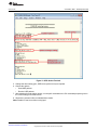
1. Setup a serial communication application (HyperTerminal/TeraTerm). For detailed information visit the
Setup Terminal on the host PC. The settings are:
• Port: Enumerated COM port (CC3200LP Dual port)
• Baud rate: 115200
• Data: 8 bit
• Parity: None
• Stop: 1 bit
• Flow control: None
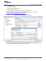
2. Run the application (tcp_socket) from IAR/CCS, or flash the bin file to device.
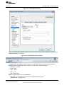
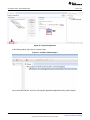
3. Connect a PC to the same AP that the device is connected to.
4. Get the IP address of the PC and fill this value for the IP_ADDR macro, or change the setting as
specified in Figure 11:
Figure 11. TCP Socket Terminal
5. Change the other setting (port, SSID name, packet count) as required.
SWRU369B – June 2014 – Revised March 2015
Submit Documentation Feedback
CC3200 SimpleLink™ Wi-Fi® and IoT Solution, a Single Chip Wireless MCU
Copyright © 2014–2015, Texas Instruments Incorporated
29
Foundation SDK – Development Flow
www.ti.com
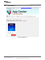
6. Choose the options:
• Send TCP packets
• Receive TCP packets
7. After selecting one of the above options, run the iperf command on the PC command prompt as given
in the TeraTerm/HyperTerminal screen.
8. Observe the execution flow to understand the results.
Note: Disable PC anti-virus while running iperf.
5.1.4
UDP Socket Application
5.1.4.1
Application Details
This application illustrates how to use the device as a client or server for UDP communication. Developers
and users can refer or re-use the function while writing new applications. The device connects to an AP
(access point), with the SSID for the AP stored as a macro in the application. Initially, the application
implements a UDP client and sends 1000 UDP packets to a socket address, port number, and IP address
specified as macros. Zero is the expected return code. A different return code indicates that a socket error
has occurred. The default setting is defined in the following macros, changed either in the source code or
at runtime.
#define
#define
#define
#define
5.1.4.2
SSID_NAME
"cc3200demo"
IP_ADDR
0xc0a8006E
PORT_NUM
5001
UDP_PACKET_COUNT
1000
Source Files Briefly Explained
The application source can be found in example\udp_socket.
• main.c – Main file calls SimpleLink APIs to connect to the network, creates a socket, and uses it to
communicate over UDP by acting as a UDP client or server.
• pinmux.c – Pinmux file to mux the device to configure the UART peripheral.
• startup_ccs.c – CCS-specific vector table implementation for interrupts
• uart_if.c – Common interface file for UART prints
• udma_if.c – Common interface file for uDMA functionalities
• startup_ewarm.c – IAR workbench-specific vector table implementation for interrupts
Supporting folders/files
The ewarm folder contains IAR workspace. The ccs folder contains CCS Project, the driverlib folder
contains all the driver files, the oslib folder contains the project to build free_rtos library, the third_party
folder contains FreeRTOS files, and the simplelink folder contains Simple Link Host Files
30
CC3200 SimpleLink™ Wi-Fi® and IoT Solution, a Single Chip Wireless MCU
SWRU369B – June 2014 – Revised March 2015
Submit Documentation Feedback
Copyright © 2014–2015, Texas Instruments Incorporated
Foundation SDK – Development Flow
www.ti.com
5.1.4.3
Code Flow Connection
void main()
{
...
// Starting SimpleLink
lRetVal = sl_Start(0, 0, 0);
...
lRetVal = WlanConnect(); /* ...
lRetVal = sl_WlanConnect(...);
...
// Wait for WLAN Event
while((!IS_CONNECTED(g_ulStatus)) || (!IS_IP_ACQUIRED(g_ulStatus)))
{ ... }
...
*/
...
/* following calls depend on user's input at runtime */
// Before proceeding, please make sure to have a server waiting on PORT_NUM
lRetVal = BsdUdpClient(PORT_NUM);
// After calling this function, you can start sending data to CC3200 IP
// address on PORT_NUM
lRetVal = BsdUdpServer(PORT_NUM);
...
}
UDP Client
int BsdUdpClient(unsigned short usPort)
{
...
//Open a socket with standard parameters
iSockID = sl_Socket(SL_AF_INET,SL_SOCK_DGRAM, 0);
if( iSockID < 0 )
{
// error
ASSERT_ON_ERROR(UCP_CLIENT_FAILED);
}
//Send packet using the sl_Send API call
iStatus = sl_SendTo(iSockID, g_cBsdBuf, sTestBufLen, 0,
( SlSockAddr_t *)&sAddr, iAddrSize);
if( iStatus <= 0 )
{
// error
ASSERT_ON_ERROR(UCP_CLIENT_FAILED);
}
//Close the socket
sl_Close(iSockID);
SUCCESS
}
Sending the UDP packets is a three step process.
1. Open the socket
2. Send the packets
3. Close the socket
SWRU369B – June 2014 – Revised March 2015
Submit Documentation Feedback
CC3200 SimpleLink™ Wi-Fi® and IoT Solution, a Single Chip Wireless MCU
Copyright © 2014–2015, Texas Instruments Incorporated
31
Foundation SDK – Development Flow
www.ti.com
UDP Server
int BsdUdpServer(unsigned short usPort)
{
...
iSockID = sl_Socket(SL_AF_INET,SL_SOCK_STREAM, 0);
if( iSockID < 0 )
{
// error
ASSERT_ON_ERROR(UCP_SERVER_FAILED);
}
...
iStatus = sl_Bind(iSockID, (SlSockAddr_t *)&sLocalAddr, iAddrSize);
if( iStatus < 0 )
{
// error
ASSERT_ON_ERROR(UCP_SERVER_FAILED);
}
iStatus = sl_RecvFrom(iNewSockID, g_cBsdBuf, iTestBufLen, 0, &sAddr, &iAddrSize);
sl_Close(iSockID);
SUCCESS
}
Steps for receiving UDP packets as a UDP server are as follows:
1. Open the socket
2. Create a UDP server
3. Receive packets
4. Close the socket
5.1.4.4
Usage
1. Set up a serial communication application (HyperTerminal/TeraTerm). For detailed information, visit the
Setup Terminal on the host PC. The settings are:
• Port: Enumerated COM port (CC3200LP Dual port)
• Baud rate: 115200
• Data: 8 bit
• Parity: None
• Stop: 1 bit
• Flow control: None
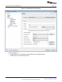
2. Run the application (udp_socket) from IAR/CCS or flash the bin file to the device.
3. Connect a PC to the same AP that the device is connected to.
4. Get the IP address of the PC and fill this value for IP_ADDR macro, or change the setting as specified
in Figure 12.
32
CC3200 SimpleLink™ Wi-Fi® and IoT Solution, a Single Chip Wireless MCU
SWRU369B – June 2014 – Revised March 2015
Submit Documentation Feedback
Copyright © 2014–2015, Texas Instruments Incorporated
Foundation SDK – Development Flow
www.ti.com
Figure 12. UDP Socket Terminal
5. Change the other setting (port, SSID name, packet count) as required.
6. Choose the options:
• Send UDP packets
• Receive UDP packets
7. After selecting from the above options, run the iperf command on the PC command prompt as given in
the TeraTerm/HyperTerminal screen.
8. Observe the execution flow to understand the results.
Note: Disable PC anti-virus while running iperf.
SWRU369B – June 2014 – Revised March 2015
Submit Documentation Feedback
CC3200 SimpleLink™ Wi-Fi® and IoT Solution, a Single Chip Wireless MCU
Copyright © 2014–2015, Texas Instruments Incorporated
33
Foundation SDK – Development Flow
5.1.5
www.ti.com
Raw Socket Application
5.1.5.1
Application Details
The transceiver mode application in the SDK showcases the use of raw socket usage in CC3200. This
example demonstrates how to build a proprietary protocol on top of a Wi-Fi PHY layer, with the user given
full flexibility to build their own packet.
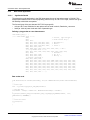
The first two bytes of the raw data are Wi-Fi PHY layer-specific.
• 1st byte: Wi-Fi rate. Definition for rate options can be found in wlan.h, RateIndex_e structure.
• 2nd byte: 4 bits of power level and 4 bits of preamble type.
Defining a ping packet as a raw data structure
char RawData_Ping[] = {
/*---- wlan header start -----*/
0x88,
0x02,
0x2C, 0x00,
0x00, 0x23, 0x75, 0x55,0x55, 0x55,
0x00, 0x22, 0x75, 0x55,0x55, 0x55,
0x08, 0x00, 0x28, 0x19,0x02, 0x85,
0x80, 0x42, 0x00, 0x00,
0xAA, 0xAA, 0x03, 0x00, 0x00, 0x00,
/*---- ip header start -----*/
0x45, 0x00, 0x00, 0x54, 0x96, 0xA1,
0x57, 0xFA,
0xc0, 0xa8, 0x01, 0x64,
0xc0, 0xa8, 0x01, 0x02,
/* payload - ping/icmp */
0x08, 0x00, 0xA5, 0x51,
0x5E, 0x18, 0x00, 0x00, 0x41, 0x08,
0x00, 0x00, 0x00, 0x00, 0x00, 0x00,
0x00, 0x00, 0x00, 0x00, 0x00, 0x00,
0x00, 0x00, 0x00, 0x00, 0x00, 0x00,
0x00, 0x00, 0x00, 0x00, 0x00, 0x00,
0x00, 0x00, 0x00, 0x00, 0x00, 0x00,
0x00, 0x00, 0x00, 0x00, 0x00, 0x00,
0x00, 0x00, 0x00, 0x00 .... };
/* version , type sub type */
/* Frame control flag */
/* destination */
/* bssid */
/* source */
0x08, 0x00, /* LLC */
0x00, 0x00, 0x40, 0x01,
/* checksum */
/* src ip */
/* dest ip */
0xBB,
0x00,
0x00,
0x00,
0x00,
0x00,
0x00,
0x8D,
0x00,
0x00,
0x00,
0x00,
0x00,
0x00,
0x00,
0x00,
0x00,
0x00,
0x00,
0x00,
0x00,
0x00,
0x00,
0x00,
0x00,
0x00,
0x00,
0x00,
0x00,
0x00,
0x00,
0x00,
0x00,
0x00,
0x00,
0x00,
0x00,
0x00,
0x00,
0x00,
0x00,
0x00,
Raw socket send
void TxContinues(int iChannel,RateIndex_e rate,int iNumberOfPackets,double dIntervalMiliSec)
{
...
// Socket open
iSoc = sl_Socket(SL_AF_RF,SL_SOCK_RAW,iChannel);
// Send the data
for(ulIndex = 0 ; ulIndex < iNumberOfPackets ; ulIndex++)
{
sl_Send(iSoc,RawData_Ping,sizeof(RawData_Ping),SL_RAW_RF_TX_PARAMS(iChannel,
iTxPowerLevel, PREAMBLE));
}
...
// Close the socket
sl_Close(iSoc);
...
}
34
CC3200 SimpleLink™ Wi-Fi® and IoT Solution, a Single Chip Wireless MCU
rate,
SWRU369B – June 2014 – Revised March 2015
Submit Documentation Feedback
Copyright © 2014–2015, Texas Instruments Incorporated
Foundation SDK – Development Flow
www.ti.com
The Rx statistics feature inspects the medium in terms of congestion and distance, validates the RF
hardware, and helps using the RSSI information.
5.1.5.2
•
•
•
•
•
Source Files Briefly Explained
main – Demonstrates sending a raw ping packet in Tx continues, and usage of different API for getting
the Rx statistics.
uart_if – Displays status information over the UART.
pinmux.c – Pinmux file to mux the device and configure the UART peripheral.
startup_ccs.c – CCS-specific vector table implementation for interrupts
startup_ewarm.c – IAR workbench-specific vector table implementation for interrupts
Supporting folders/files
The ewarm folder contains IAR workspace. The ccs folder contains CCS Project, the driverlib folder
contains all the driver files, and the simplelink folder contains Simple Link Host Files
5.1.5.3
•
•
•
Usage
Setup a serial communication application (HyperTerminal/TeraTerm).
– Port: Enumerated COM port (CC3200LP Dual Port)
– Baud rate: 115200
– Data: 8 bit
– Parity: None
– Stop: 1 bit
– Flow control: None
Run the reference application (Flashing the bin/IAR/CCS).
Observe the status messages on the host over serial port in response to the user's selection of either
"sending packets" or "Collect statistics of received packets" to understand the sequence of operations
performed by the application.
Terminal snapshot when application runs on device:
Figure 13. CC3200 Transceiver Application on the Hyperterminal
Common interface files: Common interface files are available under the example\common folder
SWRU369B – June 2014 – Revised March 2015
Submit Documentation Feedback
CC3200 SimpleLink™ Wi-Fi® and IoT Solution, a Single Chip Wireless MCU
Copyright © 2014–2015, Texas Instruments Incorporated
35
Foundation SDK – Development Flow
5.2
www.ti.com
SimpleLink APIs
WLAN APIs
APIs
Description
sl_Start
This function starts the SimpleLink (Networking) device. This function initializes the
communication interface. Once this is complete LED1 starts blinking to indicate
Sl_start is complete and waiting to complete Sl_Wlanconnect.
sl_WlanConnect
This function connects the device to AP that is specified as parameter. Once the
connection status is set, LED1 will be ON until the device is disconnected from the
AP. After a successful WLAN connect, the name of the AP to which the device is
connected is displayed on the terminal.
sl_IpConfigGet
While in DHCP mode, this function is used to get an IP address from the associated
AP. The IP address will be displayed on the terminal so that the client machine
(iperf PC) can make use of this address to connect to the device.
sl_WlanDisconnect
This function prompts the device to relinquish the connection (hence the
association) with the AP.
Note – LED functionality depends on application implementation.
Network APIs
sl_Socket
Creates UDP Socket.
sl_SendTo
Sends a Welcome message to the destination IP address, given as input. The
destination IP address is taken from Input. 200 packets will be sent to the specific
destination address if the address is mentioned in the input. If the destination
address is not mentioned, the message is broadcasted. Once this is complete an
alert will be given on UART. While the device is sending messages Led2 will be on
to indicate the device status.
sl_Bind
Binds socket. The reception port is taken as 5002 in this application.
sl_RecvFrom
Receives message from Client. The device will be waiting for 200 packets to
receive. Once the device receives 200 packets, an alert indicating the same and the
source address of the packets will be shown on UART. While receiving messages
Led4 will be on to indicate the device status.
sl_Close
Closes the socket.
Note – Number of packets and port depend on application implementation.
5.3
Compilation, Build and Execution Procedure
Refer to the IAR/CCS help documentation that contains detailed information on compiling, building, and
executing user applications. The following sections highlight key projects exercised during the
development process. The basic Wi-Fi application is taken up as a reference to demonstrate the
development environment. Similar procedures apply for any reference application or new developments.
Most of the steps mentioned here are already performed for all the reference applications (present in
examples/ folder) and captured in the project files. While using the debugger, clean and rebuild the
libraries (driverlib, simplelink, FreeRTOS) to avoid any source file association problems.
NOTE: While creating new project under this SDK call PRCMCC3200MCUInit() as the first call in
main() for proper initialization of the device.
NOTE: Visit the CC3200 TI-RTOS page before creating any TI-RTOS based application.
5.3.1
Development Environment – IAR
Follow the steps given in C:\TI\CC3200SDK\cc3200-sdk\tools\iar_patch\readme.txt to replace
iarmLMIFTDI.dll.
5.3.1.1
•
•
•
36
Creating a Project
File->New->Workspace
Project->Create New Project (Tool Chain = ARM, Project Templates = 'C')
Open Project Option and follow the settings as given in these snapshots:
CC3200 SimpleLink™ Wi-Fi® and IoT Solution, a Single Chip Wireless MCU
SWRU369B – June 2014 – Revised March 2015
Submit Documentation Feedback
Copyright © 2014–2015, Texas Instruments Incorporated
Foundation SDK – Development Flow
www.ti.com
Figure 14. CC3200 Programmer Guide IAR Project Options
5.3.1.2
Compiling a Project
Figure 15. CC3200 IAR Compiling Project
SWRU369B – June 2014 – Revised March 2015
Submit Documentation Feedback
CC3200 SimpleLink™ Wi-Fi® and IoT Solution, a Single Chip Wireless MCU
Copyright © 2014–2015, Texas Instruments Incorporated
37
Foundation SDK – Development Flow
www.ti.com
Additional include directories
• To use Driverlib APIs – Include driverlib and inc folder path
• To use Simplelink APIs – Include simplelink, simplelink\Source, and simplelink\Include folder paths
• To use Free-RTOS TI-RTOS APIs – Include oslib path
Defined symbols (MACRO definition)
• USE_FREERTOS – If application uses Free-RTOS OS
• USE_TIRTOS – If application uses TI-RTOS OS
• ewarm – Define for IAR-based application
• SL_PLATFORM_MULTI_THREADED – If application uses any OS (Free-RTOS/ TI-RTOS)
• NOTERM – If application does not need UART prints.
5.3.1.3
Linking a Project
Figure 16. CC3200 IAR Linker Project
Additional libraries
• Add library path as per application needs:
– driverlib.a : Available under the driverlib\ewarm\Release\Exe\ folder.
– simplelink.a : Available under simplelink\ewarm\OS\, simplelink\ewarm\NON_OS\,
simplelink\ewarm\NON_OS_PM, and simplelink\ewarm\PM_Framework\ folder for the OS, Non-OS,
Non-OS with power management hook, and power management configuration for OS environment,
respectively.
38
CC3200 SimpleLink™ Wi-Fi® and IoT Solution, a Single Chip Wireless MCU
SWRU369B – June 2014 – Revised March 2015
Submit Documentation Feedback
Copyright © 2014–2015, Texas Instruments Incorporated
Foundation SDK – Development Flow
www.ti.com
– free_rtos.a : Available under oslib\ewarm\free_rtos\Exe\ folder.
– ti_rtos.a : If application uses TI-RTOS, then the TI-RTOS library is available under the
oslib\ewarm\ti_rtos\Exe\ folder.
Figure 17. CC3200 IAR Linker Config
Linker configuration file
• Link to IAR linker file. By default, IAR links to CC3200.icf available in IAR installation. The developer
can change this as per application requirement.
Symbol definitions
• Define CC3200_ES_1_2_1=1 only for the XCC3101GZ device, and CC3200_ES_1_2_1=0 for other
devices.
SWRU369B – June 2014 – Revised March 2015
Submit Documentation Feedback
CC3200 SimpleLink™ Wi-Fi® and IoT Solution, a Single Chip Wireless MCU
Copyright © 2014–2015, Texas Instruments Incorporated
39
Foundation SDK – Development Flow
5.3.1.4
www.ti.com
Generating the Binary (.bin)
Figure 18. CC3200 IAR Generating Binary
To generate additional output select the output format, a current SDK user must select the ‘binary’ option
and override the .bin path. In CC3200 SDK, IAR generates bin file in the <example>\ewarm\Release\Exe
folder.
5.3.1.5
Executing a Project
To use the JTAG over FTDI, the TI Stellaris driver must be selected. The user can configure IAR to work
with JTAG/SWD by choosing the option available in Options->Debugger->TI Stellaris->Interface. On the
CC3200 Launchpad:
• JTAG Mode – connect SOP-2 jumper only
• SWD mode – connect SOP-0 jumper only
NOTE: The 4-Wire JTAG will work without connecting the SOP 2 jumper. However, TI recommends
connecting the SOP 2 jumper to prevent the already-flashed code from executing while
debugging.
40
CC3200 SimpleLink™ Wi-Fi® and IoT Solution, a Single Chip Wireless MCU
SWRU369B – June 2014 – Revised March 2015
Submit Documentation Feedback
Copyright © 2014–2015, Texas Instruments Incorporated
Foundation SDK – Development Flow
www.ti.com
Figure 19. CC3200 IAR Executing
Click on the Download and Debug button to start the execution. The execution stops at the main function.
Click the Go button (or F5) to run.
Figure 20. CC3200 IAR Download and Run
If the application uses UART to print the output on the terminal, then the user must setup a terminal
application (such as HyperTerminal or TeraTerm). These are the serial port settings:
• Baud Rate – 115200
• Data – 8 bits
• Parity – none
• Stop – 1 bit
• Flow control- none
Note: To enable UART prints in any application:
• Add UART_if.c/.h to project and do pinmux for UART peripheral (refer to
example\mode_config\pinmux.c).
SWRU369B – June 2014 – Revised March 2015
Submit Documentation Feedback
CC3200 SimpleLink™ Wi-Fi® and IoT Solution, a Single Chip Wireless MCU
Copyright © 2014–2015, Texas Instruments Incorporated
41
Foundation SDK – Development Flow
•
5.3.2
www.ti.com
Disable the NOTERM macro and call InitTerm (example\common\uart_if.c) to initialize UART at the
start of the application program.
Development Environment – TI Code Composer Studio
Current SDK supports CCS 6.0.1 version. The following are the steps to create a new project in CCS
environment.
5.3.2.1
To
•
•
•
TI-RTOS 2.0 in CCSv6
install TI-RTOS under a CCS environment:
Start the CCS and open the app center from the Help->Getting Started screen.
Search ‘CC3200’ in the app center, which results in 'CC3200 Add-on' and 'TI-RTOS for SimpleLink.'
Select and install in CCS 6.0.1
Figure 21
Figure 21. CCS App Center
42
CC3200 SimpleLink™ Wi-Fi® and IoT Solution, a Single Chip Wireless MCU
SWRU369B – June 2014 – Revised March 2015
Submit Documentation Feedback
Copyright © 2014–2015, Texas Instruments Incorporated
Foundation SDK – Development Flow
www.ti.com
5.3.2.2
Install TI-PinMux Tool
The user can install the TI-Pinmux Tool from http://www.ti.com/tool/pinmuxtool or as specified in Figure 22
Figure 22. TI-PinMux Tool
SWRU369B – June 2014 – Revised March 2015
Submit Documentation Feedback
CC3200 SimpleLink™ Wi-Fi® and IoT Solution, a Single Chip Wireless MCU
Copyright © 2014–2015, Texas Instruments Incorporated
43
Foundation SDK – Development Flow
5.3.2.3
www.ti.com
Importing a Project
The current version of the SDK supports Copy Projects into Workspace, allowing the user to modify the
example source as per requirement without touching the SDK repository.
Figure 23. Select CCS Projects to Import
If the user copies any library project (such as driverlib, simplelink, or netapps) to the workspace and
modifies it, ensure that the concerning application connects to the latest and modified >library>.a,
available in the workspace (see Figure 30).
MACRO.ini : This file is used when the user copies any example folder to their working directory and tries
to build a CCS project. Edit macro.ini and assign CC3200_SDK_ROOT to the SDK root path and import
the project into the workspace, so that the example can connect to the SDK libraries and common files.
CC3200_SDK_ROOT=C:\TI\CC3200SDK_1.0.0\cc3200-sdk
44
CC3200 SimpleLink™ Wi-Fi® and IoT Solution, a Single Chip Wireless MCU
SWRU369B – June 2014 – Revised March 2015
Submit Documentation Feedback
Copyright © 2014–2015, Texas Instruments Incorporated
Foundation SDK – Development Flow
www.ti.com
5.3.2.4
•
•
•
•
Creating a Project
File -> New -> CCS Project
Target -> Wireless Connectivity MCU
Device -> Variant -> CC3200
Open Project Option, and follow the settings as given in the snapshots.
For the application to work with TI-RTOS, ti_rtos_config project must be imported into the CCS
workspace. Refer to docs\CC3200-TI-RTOS User Guide.pdf or
http://processors.wiki.ti.com/index.php/CC32xx_TI-RTOS.
Figure 24. CC3200 CSS Editing Existing Project
Add a path variable CC3200_SDK_ROOT in the CCS project, which locates to the root folder of the
current SDK. The user can change this path to point to the desired version of the SDK path. This variable
can be used to include paths, link libraries, and common source files.
SWRU369B – June 2014 – Revised March 2015
Submit Documentation Feedback
CC3200 SimpleLink™ Wi-Fi® and IoT Solution, a Single Chip Wireless MCU
Copyright © 2014–2015, Texas Instruments Incorporated
45
Foundation SDK – Development Flow
www.ti.com
Figure 25. CC3200 CCS Creating Project
Linker command file:
• cc3200v1p32.cmd: for XCC3200JR, CC3200R1M2, and XCC3200HZ devices.
• cc3200v1p21.cmd for XCC3101GZ device.
46
CC3200 SimpleLink™ Wi-Fi® and IoT Solution, a Single Chip Wireless MCU
SWRU369B – June 2014 – Revised March 2015
Submit Documentation Feedback
Copyright © 2014–2015, Texas Instruments Incorporated
Foundation SDK – Development Flow
www.ti.com
5.3.2.5
Compiling a Project
Figure 26. CC3200 CCS Compiling Project
SWRU369B – June 2014 – Revised March 2015
Submit Documentation Feedback
CC3200 SimpleLink™ Wi-Fi® and IoT Solution, a Single Chip Wireless MCU
Copyright © 2014–2015, Texas Instruments Incorporated
47
Foundation SDK – Development Flow
www.ti.com
Figure 27. CC3200 CCS Compiling Project 1
Add dir to #include search path
• To use Driverlib APIs – Include driverlib and inc folder path.
• To use Simplelink APIs – Include simplelink, simplelink\source, and simplelink\include folder path.
• To use TI-RTOS APIs – Include oslib folder path.
• To use common interface APIs – Include example\common folder path.
48
CC3200 SimpleLink™ Wi-Fi® and IoT Solution, a Single Chip Wireless MCU
SWRU369B – June 2014 – Revised March 2015
Submit Documentation Feedback
Copyright © 2014–2015, Texas Instruments Incorporated
Foundation SDK – Development Flow
www.ti.com
Figure 28. CC3200 CCS Compiling Project 2
Pre-define NAME
• USE_TIRTOS – To use TI-RTOS OS APIs.
• USE_FREERTOS – To use Free-RTOS OS APIs.
• SL_PLATFORM_MULTI_THREADED – If application uses any OS.
• ccs – For CCS-based application
SWRU369B – June 2014 – Revised March 2015
Submit Documentation Feedback
CC3200 SimpleLink™ Wi-Fi® and IoT Solution, a Single Chip Wireless MCU
Copyright © 2014–2015, Texas Instruments Incorporated
49
Foundation SDK – Development Flow
5.3.2.6
www.ti.com
Linking a Project
Figure 29. CC3200 CCS Linking Project 1
•
50
Set heap and stack size as per the application requirements.
CC3200 SimpleLink™ Wi-Fi® and IoT Solution, a Single Chip Wireless MCU
SWRU369B – June 2014 – Revised March 2015
Submit Documentation Feedback
Copyright © 2014–2015, Texas Instruments Incorporated
Foundation SDK – Development Flow
www.ti.com
Figure 30. CC3200 CCS Linking Project 2
Include library file
• As per the application requirements, include driverlib.a, simplelink.a, ti_rtos.a, or free_rtos.a
– driverlib.a is available under the driverlib\ccs\Release folder.
– simplelink.a is available under the simplelink\ccs\OS', NON_OS,' NON_OS_PM', PM_Framework
folder for OS, non-OS, power management for non-OS, or power management for OS-based
applications respectively.
– ti_rtos.a and free_rtos.a are present under the oslib\ccs\ti_rtos and oslib\ccs\free_rtos folders,
respectively.
SWRU369B – June 2014 – Revised March 2015
Submit Documentation Feedback
CC3200 SimpleLink™ Wi-Fi® and IoT Solution, a Single Chip Wireless MCU
Copyright © 2014–2015, Texas Instruments Incorporated
51
Foundation SDK – Development Flow
5.3.2.7
www.ti.com
Dependency to Other Project
Figure 31. TI-RTOS OS Dependency
Dependencies
• If the application uses TI-RTOS OS, add ti_rtos_config project as dependency for the application.
– ti_rtos_config project should be imported in CCS workspace for TI-RTOS based application.
– Current SDK supports TI-RTOS 2.1.0.x
5.3.2.8
•
Generating a Binary (.bin)
Add the following script to generate a .bin file
"${CCE_INSTALL_ROOT}/utils/tiobj2bin/tiobj2bin" "${BuildArtifactFileName}"
"${BuildArtifactFileBaseName}.bin" "${CG_TOOL_ROOT}/bin/armofd"
"${CG_TOOL_ROOT}/bin/armhex"
"${CCE_INSTALL_ROOT}/utils/tiobj2bin/mkhex4bin"
52
CC3200 SimpleLink™ Wi-Fi® and IoT Solution, a Single Chip Wireless MCU
SWRU369B – June 2014 – Revised March 2015
Submit Documentation Feedback
Copyright © 2014–2015, Texas Instruments Incorporated
Foundation SDK – Development Flow
www.ti.com
Figure 32. CC3200 CCS Generating Binary
SWRU369B – June 2014 – Revised March 2015
Submit Documentation Feedback
CC3200 SimpleLink™ Wi-Fi® and IoT Solution, a Single Chip Wireless MCU
Copyright © 2014–2015, Texas Instruments Incorporated
53
Foundation SDK – Development Flow
5.3.2.9
www.ti.com
Executing a Project
Click on the target configuration under View.
Figure 33. CC3200 CCS Executing 1
Right Click on the User Defined, click on Import Target Configuration, and select CC3200.ccxml from
/tools/ccs/.
Figure 34. CC3200 CCS Executing 2
Set this new configuration as the default. Right click on this configuration and select Launch Selected
Configuration.
54
CC3200 SimpleLink™ Wi-Fi® and IoT Solution, a Single Chip Wireless MCU
SWRU369B – June 2014 – Revised March 2015
Submit Documentation Feedback
Copyright © 2014–2015, Texas Instruments Incorporated
Foundation SDK – Development Flow
www.ti.com
Figure 35. CC3200 CCS Launch Config
To switch between JTAG/SWD mode from CCS, follow the steps specified in Figure 36. On the CC3200
LaunchPad, configure the board for either:
• JTAG Mode – connect SOP-2 jumper only
• SWD mode – connect SOP-0 jumper only
NOTE: 4-Wire JTAG works without connecting the SOP 2 jumper. However, TI recommends
connecting the SOP 2 jumper to prevent the already-flashed code from executing while
debugging.
SWRU369B – June 2014 – Revised March 2015
Submit Documentation Feedback
CC3200 SimpleLink™ Wi-Fi® and IoT Solution, a Single Chip Wireless MCU
Copyright © 2014–2015, Texas Instruments Incorporated
55
Foundation SDK – Development Flow
www.ti.com
Figure 36. Target Configuration
In the Debug window, right click on Connect Target.
Figure 37. CC3200 CCS Executing 4
Once connected, load the .out file by selecting the appropriate application binary (Load Program).
56
CC3200 SimpleLink™ Wi-Fi® and IoT Solution, a Single Chip Wireless MCU
SWRU369B – June 2014 – Revised March 2015
Submit Documentation Feedback
Copyright © 2014–2015, Texas Instruments Incorporated
Foundation SDK – Development Flow
www.ti.com
Figure 38. CC3200 CCS Executing 5
The execution will stop at the main function. Click the Go button (or F8) to run.
For UART-based applications, configure the terminal application:
• Baud Rate – 115200
• Data – 8 bits
• Parity – none
• Stop – 1 bit
5.3.3
Development Environment – Open Source [GCC/GDB]
This platform enables open source tool chains. In this section, developers can learn how to get started
with GCC/GDB using the CC3200 LaunchPad, including the dependencies associated with the
environment setup for Windows OS under Cygwin.
Included are a few validated sample applications with GCC (including building block libraries such as
SimpleLink library and peripheral driver library).
5.3.3.1
Cygwin Installation (Windows)
Cygwin can be installed by downloading setup-x86.exe from http://cygwin.com/install.html and running it
locally. Set the proxy setting in the Cygwin installation window and proceed further. CC3200 SDK is ported
and tested with the Cygwin 32-bit version only.
Include the following packages in the Cygwin installation in addition to the base installation. The latest
versions of all packages should be acceptable.
1. Archive/unzip
2. Archive/zip
3. Devel/autoconf
4. Devel/automake
5. Devel/libtool
6. Devel/make
7. Devel/subversion (Note: if you plan to use TortoiseSVN/Windows7, skip this)
8. Devel/gcc-core
9. Devel/gcc-g++
10. Devel/gcc-mingw-core
11. Devel/gcc-mingw-g++
12. Devel/mingw-runtime
After a successful Cygwin installation, add its path (c:\cygwin\bin\) to the Windows environment variable.
SWRU369B – June 2014 – Revised March 2015
Submit Documentation Feedback
CC3200 SimpleLink™ Wi-Fi® and IoT Solution, a Single Chip Wireless MCU
Copyright © 2014–2015, Texas Instruments Incorporated
57
Foundation SDK – Development Flow
5.3.3.2
www.ti.com
GNU Tools for ARM Embedded Processors
Download the latest version of gcc-arm-none-eabi-<version>-win32.exe from https://launchpad.net/gccarm-embedded, and install it under the Cygwin root directory (Default: c:\cygwin).
5.3.3.3
Open On-Chip Debugger (OpenOCD)
Open on-chip debugger (OpenOCD) can be downloaded in source form from
http://sourceforge.net/projects/openocd/files/openocd/0.7.0/ and compiled locally.
To build OpenOCD for FTDI interface, download the FTDI driver library (x86 [32-bit] zip version) from
http://www.ftdichip.com/Drivers/D2XX.htm.
To compile OpenOCD with FTDI support (Cygwin bash shell):
1. Extract OpenOCD source into the Cygwin directory (c:\cygwin). This creates a directory called
openocd-<version> under the Cygwin directory, which contains all OpenOCD source contents.
2. Extract FTDI source into the openocd-<version> directory. This creates a directory called CDM 2.04.06
WHQL Certified; rename it to ftd2xx.
3. Change the director to openocd-<version>.
4. Run the following command at prompt:
./configure --enable-maintainer-mode --disable-werror --disable-shared --enableft2232_ftd2xx --with-ftd2xx-win32-zipdir=ftd2xx
5. This should successfully configure OpenOCD for building.
6. Run the make command followed by make install.
7. After the command runs successfully, check that openocd.exe is generated at C:\cygwin\usr\local\bin.
Add the same path to the environment variable.
5.3.3.4
Compile the GCC SDK project
Go to <cc3200-sdk>\example\getting_started_with_wlan_station \gcc\ in the command prompt and run the
following command:
make –f
Makefile
This generates a wlan_station.axf file under the gcc\exe folder.
5.3.3.5
Target Connection and Debugging (GDB)
The OpenOCD configuration file for FTDI is under cc3200-sdk\ tools\gcc_scripts\ folder (cc3200.cfg). To
test the connection to the CC3200 FTDI LaunchPad, go to the <cc3200-sdk>\tools\gcc_scripts folder, run
the following command at the Cygwin prompt window and check the output to ensure the connection
happened properly.
openocd -f cc3200.cfg
See Figure 39 for the connection output screen while the CC3200 device is connected through GDB.
58
CC3200 SimpleLink™ Wi-Fi® and IoT Solution, a Single Chip Wireless MCU
SWRU369B – June 2014 – Revised March 2015
Submit Documentation Feedback
Copyright © 2014–2015, Texas Instruments Incorporated
Foundation SDK – Development Flow
www.ti.com
Figure 39. Connection Output Screen
To start debugging using GDB on CC3200, go to <cc3200-sdk>\tools\gcc_scripts\ and run the following
command at the Cygwin prompt:
arm-none-eabi-gdb -x gdbinit<app.axf>
SWRU369B – June 2014 – Revised March 2015
Submit Documentation Feedback
CC3200 SimpleLink™ Wi-Fi® and IoT Solution, a Single Chip Wireless MCU
Copyright © 2014–2015, Texas Instruments Incorporated
59
Foundation SDK – Development Flow
www.ti.com
See Figure 40 for the debugging result of a blinky application from GCC.
Figure 40. Blinky GCC Application
On the (gdb) prompt give a 'continue' command.
GDB Quick Guide - http://users.ece.utexas.edu/~adnan/gdb-refcard.pdf
5.3.4
Setup the Terminal Application
To view the UART-based application output on the terminal screen, the user should setup the terminal
application (such as HyperTerminal or TeraTerm). Serial port settings:
• Baud Rate – 115200
• Data – 8 bits
• Parity – none
• Stop – 1 bit
60
CC3200 SimpleLink™ Wi-Fi® and IoT Solution, a Single Chip Wireless MCU
SWRU369B – June 2014 – Revised March 2015
Submit Documentation Feedback
Copyright © 2014–2015, Texas Instruments Incorporated
Foundation SDK – Development Flow
www.ti.com
5.4
Flashing and Running the .bin using Uniflash Tool
Once finalized, the binary images are flashed onto the non-volatile serial flash (SFlash) of the LaunchPad.
The application starts the execution when the LaunchPad device is powered on. The Uniflash tool flashes
the binaries onto the SFlash. The utility is available at
http://processors.wiki.ti.com/index.php/Category:CCS_UniFlash.
Follow the Uniflash Quick Start Guide to download the .bin file to the CC3200 device.
Note: Connect the SOP 2 jumper on LaunchPad before flashing any image to the device. After the
flashing is done, remove the SOP 2 jumper and reset the board to boot-up the application.
The .bin files for the reference examples are available in the folder example\<referenceapp>\ccs\Release
(as generated by CCS) and example\<referenceapp>\ewarm\Release\exe (as generated by IAR). The
application image filename must be /sys/mcuimg.bin.
SWRU369B – June 2014 – Revised March 2015
Submit Documentation Feedback
CC3200 SimpleLink™ Wi-Fi® and IoT Solution, a Single Chip Wireless MCU
Copyright © 2014–2015, Texas Instruments Incorporated
61
CC3200 ROM Services
6
www.ti.com
CC3200 ROM Services
The CC3200 ROM hosts the boot loader and peripheral driver library. The peripheral driver library is a
collection of routines that abstract the peripheral programming (refer to accompanying doxygen output in
the CC3200 SDK packages). This library is provided in the ROM to let the developer reduce the RAM
footprint of the application.
Boot loader services allow the user to update the application binary image along with other user files in
the serial flash, and are also responsible for loading the user application from the serial flash to MCU
RAM.
6.1
CC3200 Boot Loader
The CC3200 boot loader resides in the ROM of the application processor.
• Update/Download – The boot loader downloads an application image from the PC to the CC3200
device. The Bootloader-DNLD functionality is only triggered when the board is in UARTLOAD Sense
On Power (SOP) mode.
• Bootstrap – The boot loader is responsible for scanning a valid application image (binary) in the serial
flash (for the CC3200R device). Subsequently, the image is loaded to internal memory and execution
control is passed on to the user program.
6.1.1
Boot Loader Modes – Impact of Device “Sense On Power” (SOP) Pin
The CC3200 device has three SOP pins. A detailed explanation of the functionality is described in the
data sheet (SWRS166). In the context of the boot loader there are two modes:
• A setting corresponding to SOP[2:0] = 0b100, makes the boot loader enter the DOWNLOAD mode; in
this mode an external intervention triggers an operation – for example a “break” signal on UART from
the SimpleLink programming application, followed by a sequence to push the application image to the
device serial flash.
• A setting corresponding to SOP[2:0] = 0b000 instructs the boot loader to load the application image
from the SFLASH to the internal MCU RAM.
6.1.2
Boot Loader / User Application – Sharing MCU RAM
In DOWNLOAD mode, the boot loader requires memory resources acquired from the MCU RAM. The
amount of RAM used by the boot loader is 16 KB. This implies that for the production variant of a CC3200
device, the user application image must be restricted to 240 KB for the 256-KB MCU RAM variant of the
CC3200. There are several key points for developers:
• MCU RAM address range 0x20000000 - 0x20003FFF: This area is shared between the application and
the boot loader. The developer can only locate application data sections, as data sections are not part
of the application image; this ensures that when the boot loader is loading the application image from
serial flash to RAM, this memory region is made exclusive to the boot loader. Once the boot loader
launches the application, this memory region can be used by the application for its data sections.
• 0x20004000 to END of RAM: This RAM area is exclusively for the application. The application image
should always be within this region and start at 0x20004000.
• RAM range for different variants:
– CC3200R1M1: 0x20004000 - 0x20020000
– XCC3200JR, CC3200R1M2: 0x20004000 - 0x20040000
– XCC3200HZ: 0x20004000 - 0x20030000
Note: Refer to the Blinky Linker command file (CCS /IAR / GCC), which defines 240 KB of RAM for the
XCC3200JR and CC3200R1M2 devices.
62
CC3200 SimpleLink™ Wi-Fi® and IoT Solution, a Single Chip Wireless MCU
SWRU369B – June 2014 – Revised March 2015
Submit Documentation Feedback
Copyright © 2014–2015, Texas Instruments Incorporated
CC3200 ROM Services
www.ti.com
Table 3. End of RAM
END of RAM
Exclusively for application. Application should be part of this region and start at 0x20004000
[0x20004000]
16 KB Shared between boot loader and application
[0x20000000]
6.2
CC3200 Peripheral Driver Library Services in ROM
Peripheral driver routines are used in the CC3200 MCU ROM for linking with user applications. Entire
source codes of the peripheral driver routines are available in the CC3200 SDK. The developer could
choose to build an application with the library while instructing the linker to use routines directly from RAM.
The focus of this section is to appraise the developer on how to use these routines, and the procedure to
patch or extend any existing routines.
6.2.1
Peripheral Library Access in ROM
ROM APIs are invoked using the following re-direction flow to allow future extensions while retaining
backward compatibility of location of access functions in the ROM memory map. While the API locations
may change in future versions of the ROM, the API tables will not.
Two tables in the ROM resolve to the entry point of each supported API. Access is made through two
levels; the main table contains one pointer per peripheral, which points to a secondary table that contains
one pointer per API associated with that peripheral.
The main table is located at address 0x0000040C in the ROM. The following table shows a small portion
of the API tables in a graphical form to illustrate the arrangement of the tables:
Table 4. ROM APIs
ROM_API TABLE (at 0x0000040C)
[0] = RESERVED
[1] = pointer to ROM_UARTTABLE
[2] = pointer to ROM_TIMERTABLE
[3] = pointer to ROM_WATCHDOGTABLE
[4] = pointer to ROM_INTERRUPTTABLE
[5] = pointer to ROM_UDMATABLE
[6] = pointer to ROM_PRCMTABLE
[7] = pointer to ROM_I2CTABLE
……
Table 5. ROM Interrupts
ROM_INTERRUPT TABLE
[0] = pointer to ROM_IntEnable
[1] = pointer to ROM_IntMasterEnable
[2] = pointer to ROM_IntMasterDisable
The address of the ROM_INTERRUPTTABLE table is located in the memory location at 0x0000041C. The
address of the ROM_IntMasterEnable () function is contained at offset 0x4 from that table. In the function
documentation, ROM_APITABLE is an array of pointers located at 0x0000040C.
ROM_INTERRUPTTABLE is an array of pointers located at ROM_APITABLE[4].
ROM_IntMasterEnable is a function pointer located at ROM_INTERRUPTTABLE [1].
SWRU369B – June 2014 – Revised March 2015
Submit Documentation Feedback
CC3200 SimpleLink™ Wi-Fi® and IoT Solution, a Single Chip Wireless MCU
Copyright © 2014–2015, Texas Instruments Incorporated
63
CC3200 ROM Services
6.2.2
www.ti.com
Linking User Application with ROM APIs
Using the ROM driver lib APIs for devices before ES 1.32 is not recommended, as the number of APIs
that would need to be patched would be higher. Nevertheless, below are the steps to use ROM driver lib
APIs instead of the RAM APIs. These APIs could be used with the production version of a CC3200
device. These steps apply to all relevant source and project files that use driver lib APIs, such as the
SimpleLink and oslib library.
1. All the .c files which use driver lib APIs should include these header files in order:
• #include rom.h
• #include rom_map.h
2. All the project files should add the global preprocessor define TARGET_IS_CC3200.
3. All driver lib APIs should be invoked by MAP_apiname instead of apiname. For example, use
MAP_UARTCharPut instead of UARTCharPut. Any changes or additions should follow this approach.
4. Rebuild all relevant projects.
6.2.3
Patching ROM APIs
Follow these steps to selectively patch the ROM driver lib APIs. Note that “patch” in this description means
using the RAM driver lib API instead of the ROM driver lib API.
1. Add an entry in the file \driverlib\rom_patch.h for all APIs to be patched.
2. For example, to patch MAP_UARTCharPut and MAP_UARTBreakCtl entries in file rom_patch.h:
• #undef ROM_UARTCharPut
• #undef ROM_UARTBreakCtl
3. Rebuild all the relevant projects that use driver lib APIs.
6.2.4
Linking with RAM-based Peripheral Driver Library
To de-link all ROM driver lib APIs and use the RAM driver lib APIs, follow these steps:
1. Remove the global preprocessor define TARGET_IS_CC3200 from all project files that use driver lib
APIs.
2. Rebuild all the relevant projects that use driver lib APIs.
64
CC3200 SimpleLink™ Wi-Fi® and IoT Solution, a Single Chip Wireless MCU
SWRU369B – June 2014 – Revised March 2015
Submit Documentation Feedback
Copyright © 2014–2015, Texas Instruments Incorporated
Additional Resources
www.ti.com
7
Additional Resources
Visit these links for additional resources on the SimpleLink Wi-Fi CC3200 and IoT Solution, a single chip
wireless MCU device.
• CC32xx Wiki – All additional resources.
• TI Product Folder for CC32xx.
• CC32xx SimpleLink Host Driver APIs and CC32xx Peripheral Drivers APIs.
• CC32xx Technical Reference Manual.
SWRU369B – June 2014 – Revised March 2015
Submit Documentation Feedback
CC3200 SimpleLink™ Wi-Fi® and IoT Solution, a Single Chip Wireless MCU
Copyright © 2014–2015, Texas Instruments Incorporated
65
Revision History
www.ti.com
Revision History
Changes from July 1, 2014 to March 11, 2015 ................................................................................................................ Page
•
•
•
•
•
•
•
•
•
•
•
Added Application Bootloader, HTTP Client Demo, Idle Profile (Non-OS), MQTT Client, MQTT Server, OTA Updated,
Dynamic Library Loader to examples in Package Contents table. ................................................................
Added http, json, and mqtt to NetApps in Package Contents table. ..............................................................
Added Simplelink_extlib and Documents values to Package Contents table. ...................................................
Updated image. ..........................................................................................................................
Updated image. ..........................................................................................................................
Added HTTP Client Demo, Idle Profile (Non OS), MQTT Client, MQTT Server, and OTA Update to table. ................
Added Application Bootloader and Dynamic Library Loader to table. ............................................................
Updated Simple Networking Applications section. ..................................................................................
Added Note. ..............................................................................................................................
Added Note. ..............................................................................................................................
Updated RAM range. ....................................................................................................................
12
12
12
16
16
19
20
22
40
55
62
Revision History
Changes from Original (June 2014) to A Revision ......................................................................................................... Page
•
•
•
•
•
•
•
•
•
•
•
•
•
•
•
•
•
•
•
•
•
•
•
•
•
•
•
•
•
66
Changed to xCC3200HZ and XCC3101GZ. ........................................................................................... 5
Added Watchdog System Demo, TFTP Client, and WebSocket Camera values ............................................... 11
Added NetApps values to Package Contents table. ................................................................................ 12
Added Watchdog System Demo, TFTP Client, and WebSocket Camera to table. ............................................. 19
Deleted security macro. ................................................................................................................. 22
Added pinmux, gpio, and uart values. ................................................................................................ 22
Updated Code Flow Connection. ...................................................................................................... 24
Reworded Step Five. .................................................................................................................... 24
Added pinmux and uart values. ........................................................................................................ 24
Updated Code Flow Connection. ...................................................................................................... 25
Updated Application Details section. .................................................................................................. 26
Added uart and udma values. .......................................................................................................... 26
Updated Code Flow Connection. ...................................................................................................... 27
Updated Application Details. ........................................................................................................... 30
Added uart and udma values. .......................................................................................................... 30
Updated Code Flow Connection. ...................................................................................................... 32
Added pinmux, startup_ccs, and startup_ewarm values............................................................................ 35
Added NOTERM bullet point ........................................................................................................... 38
Added Note ............................................................................................................................... 41
Added Importing a Project section. .................................................................................................... 44
Added macro.ini paragraph. ............................................................................................................ 44
Added image.............................................................................................................................. 45
Updated image. .......................................................................................................................... 46
Updated images. ......................................................................................................................... 47
Updated image. .......................................................................................................................... 48
Updated image. .......................................................................................................................... 51
Added RAM range for different variants. ............................................................................................. 62
Deleted Changed from0x0000042C to 0x0000041C. ............................................................................... 63
Changed from ROM_APITABLE[5] to ROM_APITABLE[4]. ....................................................................... 63
Revision History
SWRU369B – June 2014 – Revised March 2015
Submit Documentation Feedback
Copyright © 2014–2015, Texas Instruments Incorporated
IMPORTANT NOTICE
Texas Instruments Incorporated and its subsidiaries (TI) reserve the right to make corrections, enhancements, improvements and other
changes to its semiconductor products and services per JESD46, latest issue, and to discontinue any product or service per JESD48, latest
issue. Buyers should obtain the latest relevant information before placing orders and should verify that such information is current and
complete. All semiconductor products (also referred to herein as “components”) are sold subject to TI’s terms and conditions of sale
supplied at the time of order acknowledgment.
TI warrants performance of its components to the specifications applicable at the time of sale, in accordance with the warranty in TI’s terms
and conditions of sale of semiconductor products. Testing and other quality control techniques are used to the extent TI deems necessary
to support this warranty. Except where mandated by applicable law, testing of all parameters of each component is not necessarily
performed.
TI assumes no liability for applications assistance or the design of Buyers’ products. Buyers are responsible for their products and
applications using TI components. To minimize the risks associated with Buyers’ products and applications, Buyers should provide
adequate design and operating safeguards.
TI does not warrant or represent that any license, either express or implied, is granted under any patent right, copyright, mask work right, or
other intellectual property right relating to any combination, machine, or process in which TI components or services are used. Information
published by TI regarding third-party products or services does not constitute a license to use such products or services or a warranty or
endorsement thereof. Use of such information may require a license from a third party under the patents or other intellectual property of the
third party, or a license from TI under the patents or other intellectual property of TI.
Reproduction of significant portions of TI information in TI data books or data sheets is permissible only if reproduction is without alteration
and is accompanied by all associated warranties, conditions, limitations, and notices. TI is not responsible or liable for such altered
documentation. Information of third parties may be subject to additional restrictions.
Resale of TI components or services with statements different from or beyond the parameters stated by TI for that component or service
voids all express and any implied warranties for the associated TI component or service and is an unfair and deceptive business practice.
TI is not responsible or liable for any such statements.
Buyer acknowledges and agrees that it is solely responsible for compliance with all legal, regulatory and safety-related requirements
concerning its products, and any use of TI components in its applications, notwithstanding any applications-related information or support
that may be provided by TI. Buyer represents and agrees that it has all the necessary expertise to create and implement safeguards which
anticipate dangerous consequences of failures, monitor failures and their consequences, lessen the likelihood of failures that might cause
harm and take appropriate remedial actions. Buyer will fully indemnify TI and its representatives against any damages arising out of the use
of any TI components in safety-critical applications.
In some cases, TI components may be promoted specifically to facilitate safety-related applications. With such components, TI’s goal is to
help enable customers to design and create their own end-product solutions that meet applicable functional safety standards and
requirements. Nonetheless, such components are subject to these terms.
No TI components are authorized for use in FDA Class III (or similar life-critical medical equipment) unless authorized officers of the parties
have executed a special agreement specifically governing such use.
Only those TI components which TI has specifically designated as military grade or “enhanced plastic” are designed and intended for use in
military/aerospace applications or environments. Buyer acknowledges and agrees that any military or aerospace use of TI components
which have not been so designated is solely at the Buyer's risk, and that Buyer is solely responsible for compliance with all legal and
regulatory requirements in connection with such use.
TI has specifically designated certain components as meeting ISO/TS16949 requirements, mainly for automotive use. In any case of use of
non-designated products, TI will not be responsible for any failure to meet ISO/TS16949.
Products
Applications
Audio
www.ti.com/audio
Automotive and Transportation
www.ti.com/automotive
Amplifiers
amplifier.ti.com
Communications and Telecom
www.ti.com/communications
Data Converters
dataconverter.ti.com
Computers and Peripherals
www.ti.com/computers
DLP® Products
www.dlp.com
Consumer Electronics
www.ti.com/consumer-apps
DSP
dsp.ti.com
Energy and Lighting
www.ti.com/energy
Clocks and Timers
www.ti.com/clocks
Industrial
www.ti.com/industrial
Interface
interface.ti.com
Medical
www.ti.com/medical
Logic
logic.ti.com
Security
www.ti.com/security
Power Mgmt
power.ti.com
Space, Avionics and Defense
www.ti.com/space-avionics-defense
Microcontrollers
microcontroller.ti.com
Video and Imaging
www.ti.com/video
RFID
www.ti-rfid.com
OMAP Applications Processors
www.ti.com/omap
TI E2E Community
e2e.ti.com
Wireless Connectivity
www.ti.com/wirelessconnectivity
Mailing Address: Texas Instruments, Post Office Box 655303, Dallas, Texas 75265
Copyright © 2015, Texas Instruments Incorporated