1
Application Report
SPMA040A – January 2012 – Revised November 2012
Using SYS/BIOS With Stellaris® ARM® Cortex™-M3
Microcontrollers
Peggy Liska
................................................................................................. Stellaris® Microcontrollers
ABSTRACT
This document provides a brief overview of the Texas Instruments’ SYS/BIOS Real-Time Operating
System (RTOS) and outlines how to implement SYS/BIOS on the Stellaris® ARM® Cortex™-M3 family of
microcontrollers. In addition to setting up and running an example project provided within the SYS/BIOS
software package, this document outlines the process of creating a new SYS/BIOS project with the Code
Composer Studio™ v4.2 (CCS) integrated development environment (IDE). As a final step, this document
outlines the integration of the StellarisWare® Application Programming Interfaces (APIs) into a SYS/BIOS
project.
1
2
3
4
5
6
7
Contents
Introduction .................................................................................................................. 2
Overview of SYS/BIOS ..................................................................................................... 2
Downloading SYS/BIOS .................................................................................................. 16
Running an Existing SYS/BIOS Project ................................................................................ 18
Creating a Sample SYS/BIOS Project .................................................................................. 22
Conclusion .................................................................................................................. 41
References ................................................................................................................. 41
List of Figures
.......................................................................................................
1
Opening the .cfg File
2
Configuration Tool Overview .............................................................................................. 3
3
Adding and Removing Modules ........................................................................................... 4
4
Creating New Module Instances .......................................................................................... 4
5
Edit Module Options ........................................................................................................ 5
6
Text-Based Editor ........................................................................................................... 5
7
Implicit Thread Priority Levels ............................................................................................. 6
8
Foreground and Background Scheduling ................................................................................ 7
9
Hardware Versus Software Interrupts .................................................................................... 8
10
HWI and SWI Example ..................................................................................................... 9
11
Same Priority SWIs ......................................................................................................... 9
12
Task State Diagram ....................................................................................................... 11
13
Task Continues to Run After Semaphore_Pend()
14
Blocking a Task With a Semaphore..................................................................................... 12
15
Unblocking a Task With a Semaphore
16
17
....................................................................
.................................................................................
Unblocking a Task With a Semaphore When Multiple Tasks Are Blocked ........................................
Real-Time Analysis Tools ................................................................................................
3
12
13
13
15
Code Composer Studio is a trademark of Texas Instruments.
Stellaris, StellarisWare are registered trademarks of Texas Instruments.
Cortex is a trademark of ARM Limited.
ARM is a registered trademark of ARM Limited.
All other trademarks are the property of their respective owners.
SPMA040A – January 2012 – Revised November 2012
Submit Documentation Feedback
Using SYS/BIOS With Stellaris® ARM® Cortex™-M3 Microcontrollers
Copyright © 2012, Texas Instruments Incorporated
1
Introduction
1
www.ti.com
Introduction
SYS/BIOS is a real-time operating system (RTOS) kernel created by Texas Instruments (TI) that is
intended to be used in embedded applications on a variety of the TI microprocessors and microcontrollers
including the Stellaris Cortex-M3 family of devices. Several key benefits of the SYS/BIOS RTOS include:
• Scheduling
• Pre-emptive, deterministic multi-tasking
• Configuration tools
• Memory management
• Hardware abstraction for cross-platform applications
SYS/BIOS is included in the installation of Code Composer Studio (CCS), so creating a new project is
fairly straightforward. The configuration of the kernel is abstracted from the hardware by the SYS/BIOS
configuration tool called XGConf, which is based on the open-source XDCTools. This tool is a graphical
user interface (GUI) that allows for quick and easy manipulation of the RTOS components such as tasks,
interrupts, and semaphores. This GUI is incorporated into CCS and automatically generates the required
initialization code for configuring the SYS/BIOS kernel.
The remainder of this document describes the SYS/BIOS kernel in detail and the process of implementing
a SYS/BIOS-based project on a Stellaris ARM Cortex-M3 microcontroller. More detailed information about
the SYS/BIOS RTOS can be found in documents listed in Section 7, References.
2
Overview of SYS/BIOS
SYS/BIOS is an RTOS kernel designed by Texas Instruments to run on a variety of TI microcontrollers.
SYS/BIOS provides the following features:
• Preemptive, priority-based scheduler
• Memory allocation and stack management
• I/O services
The preemptive, priority-based scheduler ensures that the highest priority thread that is ready to run is
executed by the system. This configuration ensures that time-sensitive computations are handled with a
minimum amount of latency. The SYS/BIOS kernel can be optimized for custom projects in order to
improve the code size of the final application. Detailed timing and size benchmark information can be
found on the SYS/BIOS Wiki page located on the Texas Instruments Embedded Processor Wiki.
An advantage of using SYS/BIOS is the application portability between TI digital signal processors
(DSPs), ARM-based microcontrollers, and MSP430 microcontrollers. The abstraction accomplished by the
RTOS allows for code to be ported between the various product families with little to no modification
required.
This overview is based on SYS/BIOS version 6.32.02.39. Different versions of SYS/BIOS may contain
slightly different features.
2.1
Configuration Tools
The configuration of the SYS/BIOS kernel is saved in the *.cfg file in the project. This file defines the basic
parameters for modules used in the system as well as any statically-defined instances of modules.
The configuration file can be modified using one of two methods:
• Graphically (using the XGCONF configuration utility)
• Textually (using the XDCScript editor or other text editor)
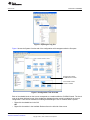
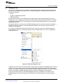
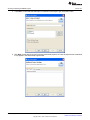
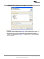
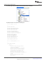
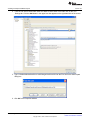
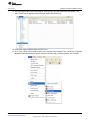
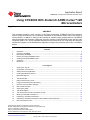
After a project is loaded into CCS, open the *.cfg file by right-clicking the file in the project and selecting
Open with > XGCONF as shown in Figure 1. For instructions on opening a SYS/BIOS project in CCS, see
Section 4, Running an Existing SYS/BIOS Project.
2
Using SYS/BIOS With Stellaris® ARM® Cortex™-M3 Microcontrollers
SPMA040A – January 2012 – Revised November 2012
Submit Documentation Feedback
Copyright © 2012, Texas Instruments Incorporated
Overview of SYS/BIOS
www.ti.com
Figure 1. Opening the .cfg File
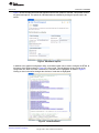
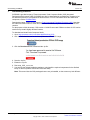
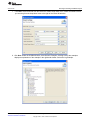
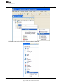
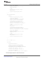
Figure 2 shows the System Overview tab of the configuration tool that appears after the file opens.
Shaded boxes indicate
SYS/BIOS kernel module
Check marks indicate
module is enabled
Figure 2. Configuration Tool Overview
Each of the shaded blocks on the screen corresponds to a module within the SYS/BIOS kernel. The check
mark in the lower left hand corner of the shaded box indicates that the module is enabled in the current
configuration. There are two methods for enabling and disabling the use of modules within a system:
• Right-click the shaded box in the GUI
OR
• Right-click the module in the Available Products list on the left side of the screen
SPMA040A – January 2012 – Revised November 2012
Submit Documentation Feedback
Using SYS/BIOS With Stellaris® ARM® Cortex™-M3 Microcontrollers
Copyright © 2012, Texas Instruments Incorporated
3
Overview of SYS/BIOS
www.ti.com
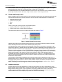
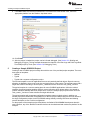
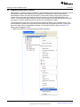
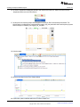
Figure 3 shows the two methods for adding and removing modules in a SYS/BIOS project.
OR
Figure 3. Adding and Removing Modules
Instances of enabled modules can be removed from or added statically to a program using two methods:
• Right-click the shaded box in the GUI
OR
• Right-click the item in the outline
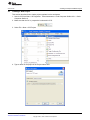
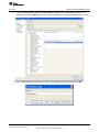
Figure 4 shows the two methods for creating a new task within a program. Note that instances of modules
can be created and configured dynamically at run-time using calls to the SYS/BIOS application
programming interfaces (APIs).
OR
Figure 4. Creating New Module Instances
Double-clicking the shaded box or clicking the item in the outline opens a window with the available
options for the module.
4
Using SYS/BIOS With Stellaris® ARM® Cortex™-M3 Microcontrollers
SPMA040A – January 2012 – Revised November 2012
Submit Documentation Feedback
Copyright © 2012, Texas Instruments Incorporated
Overview of SYS/BIOS
www.ti.com
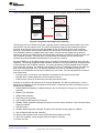
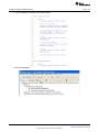
Figure 5 shows the options window that appears when the task module is selected. This window controls
the global task options. The options for individual tasks are modified by clicking the specific task in the
outline.
Figure 5. Edit Module Options
In addition to the graphical configuration utility, a text-based editor can be used to configure the RTOS. At
the bottom of the window shown in Figure 5 is a Source tab. This tab displays the text version of the
configuration file. When a module is selected, the relevant code is highlighted, as shown in Figure 6.
Clicking an item in the outline changes the sections of code that are highlighted.
Figure 6. Text-Based Editor
SPMA040A – January 2012 – Revised November 2012
Submit Documentation Feedback
Using SYS/BIOS With Stellaris® ARM® Cortex™-M3 Microcontrollers
Copyright © 2012, Texas Instruments Incorporated
5
Overview of SYS/BIOS
www.ti.com
The text-based editor can be opened outside of the GUI editor by right-clicking the .cfg file in the project
and selecting either Open With > XDCScript Editor or Open With > Text Editor.
A detailed description of the available parameters is found in the API Reference in the SYS/BIOS section
of the Help Contents found in the Help > Help Contents menu of Code Composer Studio.
2.2
Threads and Priority Levels
Within SYS/BIOS, the term thread refers to a set of instructions that can be executed by the CPU after the
required registers have been properly initialized. The four types of threads available in SYS/BIOS are:
• Hardware interrupt (HWI)
• Software interrupt (SWI)
• Task
• Idle
There are two types of priority levels in a SYS/BIOS system:
• Implicit priority levels—defined by thread type
• Explicit priority levels—defined by the programmer
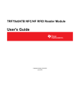
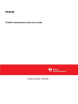
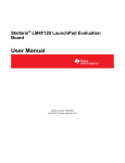
The implicit priority levels for the four main thread types are shown in Figure 7.
Figure 7. Implicit Thread Priority Levels
Hardware interrupts have the highest implicit priority level in the system followed by software interrupts,
tasks, and finally idle tasks, which have the lowest implicit priority level.
The individual HWIs, SWIs, and tasks can be assigned explicit priority levels that are secondary to the
implicit priority levels. On Stellaris devices, the maximum number of hardware interrupt priorities is 8, the
maximum number of software interrupt priorities is 32, and the maximum number of task priorities is 32.
The priority levels assigned to HWIs in a SYS/BIOS-based program changes based on the hardware for
which the code is compiled to run. On Stellaris devices, the highest priority HWI has a value of 0 and the
lowest value depends on the number of priority levels defined for HWIs. SWIs and tasks inherit the
SYS/BIOS default priority levels such that the lowest priority has a value of 0. The highest priority level
value for SWIs and tasks depends upon the number of software interrupt priority levels and task priority
levels that are implemented.
The preemptive, priority-based scheduler ensures that the highest priority thread that is ready to run is
executed by the CPU. A number of threads can be ready to execute at any given time, but the thread with
the highest priority executes first. In order to switch between threads, the context of the thread must be
saved. This context includes the program counter, the stack, and any relevant register values. Specific
stack functionality for each thread type is included in the following sections.
2.3
Hardware Interrupts
Programs without an RTOS typically have a low-priority infinite while loop that is interrupted by a highpriority interrupt service routine (ISR). This type of system allows for two priority levels in a foreground and
background scheduling system. This configuration is not easily scalable and is often insufficient for
complex systems that require multiple priority levels. A SYS/BIOS-based system introduces threading
services that allow for these multiple priority levels and deterministic scheduling.
6
Using SYS/BIOS With Stellaris® ARM® Cortex™-M3 Microcontrollers
SPMA040A – January 2012 – Revised November 2012
Submit Documentation Feedback
Copyright © 2012, Texas Instruments Incorporated
Overview of SYS/BIOS
www.ti.com
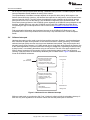
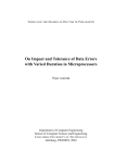
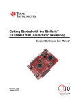
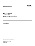
Figure 8 shows the relationship between a typical program and a program based on the SYS/BIOS RTOS.
while(1){
non real-time
}
}
Idle loop
Loop with non realtime work
ISR
get buffer
process it
printf()
Hwi
get buffer
process it
Log_print0()
BIOS Scheduler
maim()
{
init
BIOS_start()
}
maim()
{
init
Figure 8. Foreground and Background Scheduling
The Idle loop runs as the lowest priority and is typically used for activating low-power modes, built-in self
tests (BISTs), and user interface code. This loop is preempted by higher priority threads and resumes
execution at the point where the loop was preempted as soon as the higher priority code completes
execution. The hardware interrupt (HWI) replaces the functionality of the interrupt service routine (ISR).
The SYS/BIOS scheduler is wrapped around the system to ensure that the highest priority thread is
executed as soon as the thread is ready and that program execution is returned to the Idle loop when the
HWI completes execution. The BIOS_start( ) function starts the scheduler after the main program
initializes the required hardware and peripherals in the main Init( ) function.
An optional addition to a SYS/BIOS program which is enabled in the default configuration is the Interrupt
Dispatcher. The Interrupt Dispatcher allows hardware interrupts to run properly with other threads because
of its knowledge of the SYS/BIOS scheduler. Low priority threads are properly disabled when the higher
priority tasks are executing. The dispatcher also enables several of the debugging features that allow the
user to see when interrupts occur. The interrupt dispatcher is a piece of code that is common to all
interrupts so the dispatcher can reduce the footprint size of the code. The Interrupt Dispatcher consists of
three components:
• Interrupt vectors—the location of the dispatcher is patched into the interrupt vector table
• Dispatch table—contains parameters for the hardware interrupt
• Interrupt stack—saves the context when interrupts preempt each other
Following is an outline of the operation of the Interrupt Dispatcher. The steps in parentheses ( ) can be
optimized out depending on the configuration of the system. Configured zero latency interrupts are never
disabled by the dispatcher.
1. Globally disable all dispatcher managed interrupts, but not zero latency interrupts, for critical section
protection
2. (Disable Task scheduler)
3. (Disable SWI scheduler)
4. Save interrupt return pointer
5. (Call configured HWI begin hook functions)
6. (Globally enable dispatcher managed interrupts, but not zero latency interrupts, if auto-interrupt-nesting
support is enabled)
7. Call ISR function
8. (Globally disable dispatcher managed interrupts if auto-interrupt-nesting support is enabled)
9. (Call configured HWI end hook functions)
10. (Run the SWI scheduler which runs any SWIs that were posted by the ISR)
11. (Run Task scheduler, which manages Task pre-emption if required)
12. Return from ISR
SPMA040A – January 2012 – Revised November 2012
Submit Documentation Feedback
Using SYS/BIOS With Stellaris® ARM® Cortex™-M3 Microcontrollers
Copyright © 2012, Texas Instruments Incorporated
7
Overview of SYS/BIOS
www.ti.com
Do not use the interrupt keyword when defining a hardware interrupt within a SYS/BIOS program since the
Interrupt Dispatcher already handles the saving of the context.
The implementation of hardware interrupts depends on the specific device family. With respect to the
Stellaris Cortex-M3 family of devices, the hardware interrupts can be configured to use the Nested Vector
Interrupt Controller (NVIC). The NVIC allows the application to take advantage of the minimal interrupt
latency built into the core, but the latency is not the default configuration of the SYS/BIOS kernel. The
Zero-Latency-Interrupt feature of the SYS/BIOS system bypasses the SYS/BIOS interrupt dispatcher and,
therefore, prohibits ISRs from using the SYS/BIOS services and APIs. Additional information about
incorporating this type of interrupt structure can be found on the SYS/BIOS for Stellaris Devices Wiki
page.
Find more detailed information about hardware interrupts in the SYS/BIOS API Reference in the
SYS/BIOS section of the Help Contents found in the Help > Help Contents menu of Code Composer
Studio.
2.4
Software Interrupts
Hardware interrupts are often used to service time-sensitive resources. However, once these data have
been collected, the data can be passed to a less-restrictive thread for further processing. In SYS/BIOS,
software interrupts (SWIs) are often used to process hardware interrupt data. They are preemptive and
generally have a priority between 0–15. SWIs operate from a single stack which reduces the memory size
of the overall application but prevents SWIs from blocking on semaphores, suspending themselves using
a sleep function, or terminating themselves using an exit function. The size of the stack required for the
SWIs is directly proportional to the number of priority levels that the system needs. The saving and
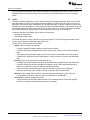
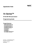
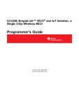
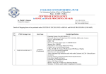
restoring of the SWI context is automatically handled by the SYS/BIOS kernel. Figure 9 shows how SWIs
fit into the SYS/BIOS architecture.
Hard Real-time
Interrupt
(from hardware)
Hardware Interrupts (Hwi)
> Urgent response time
> Often at “sample rate”
> Microseconds duty cycle
> Preemptive or non-preemptive
Foreground
Swi_post()
(from program)
Software Interrupts (Swi)
> Flexible processing time
> Often at “frame rate”
> Milliseconds duty cycle
> Preemptive
Idle
> Best Effort
> Sequential Execution
Soft Real-time
Background
Figure 9. Hardware Versus Software Interrupts
SWIs are made ready to run when the Swi_Post( ) function is called, typically by a hardware interrupt. A
SWI runs only once regardless of the number of times the SWI was posted prior to execution.
8
Using SYS/BIOS With Stellaris® ARM® Cortex™-M3 Microcontrollers
SPMA040A – January 2012 – Revised November 2012
Submit Documentation Feedback
Copyright © 2012, Texas Instruments Incorporated
Overview of SYS/BIOS
www.ti.com
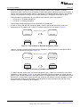
Figure 10 shows how a system with hardware and software interrupts enabled processes the two threads.
Collect Samples
Post Swi
Process Buffer
Highest Priority
Hwi
8
9
1
2
3
Swi
Legend
Idle/LPM
Running
Ready
Lowest Priorty
time
Figure 10. HWI and SWI Example
The HWI is used to collect samples in a periodic time frame and place them into a buffer. The SWI is then
used to process one of the samples (for example, sample 9). The processing of this data takes longer
than the time between samples. Using this configuration, the HWI is able to retrieve the new data while
the SWI continues to process the previous sample. As soon as both the HWI and SWI are finished
processing, the Idle thread regains control of the system.
SWIs of the same priority are processed in a first in first out (FIFO)-type system. Figure 11 shows an
instance where this may occur and how the interrupts are processed.
Swi_post(& Swi_b)
Highest Priority
HWI
Swi_b (p1)
Swi_a (p1)
Legend
IDL/LPM
Running
Ready
Lowest Priorty
time
Figure 11. Same Priority SWIs
Swi_a and Swi_b are both set to the same priority level of 1. A HWI preempts the execution of Swi_a and
during its process, posts a call to Swi_b. Since the SWIs are of equal priorities, Swi_a must complete
executing its instructions before Swi_b can begin executing. As soon as both of the SWIs are done
executing, program control is returned to the Idle thread.
Although SWIs only run once regardless of the number of times the SWIs were posted prior to execution,
you can also determine how many times a SWI was posted. The Swi_inc( ) function returns the number of
times the SWI was posted before the SWI ran. You can also schedule a SWI after the SWI has been
called multiple times. The Swi_dec( ) function requires that the SWI is posted an explicit number of times
before the SWI is scheduled. These and other functions are explained in further detail in the SYS/BIOS
API Reference in the SYS/BIOS section of the Help Contents found in the Help > Help Contents menu of
Code Composer Studio.
SPMA040A – January 2012 – Revised November 2012
Submit Documentation Feedback
Using SYS/BIOS With Stellaris® ARM® Cortex™-M3 Microcontrollers
Copyright © 2012, Texas Instruments Incorporated
9
Overview of SYS/BIOS
www.ti.com
Find more detailed information about software interrupts in the Software Interrupt Run-Time API in the
SYS/BIOS section of the Help Contents found in the Help > Help Contents menu of Code Composer
Studio.
2.5
Tasks
The third SYS/BIOS thread type is a task. Unlike hardware and software interrupts, tasks can block and
allow other tasks to execute. This requires that each instance of a task has its own stack in memory as
opposed to the common stack model that is used by SWIs and HWIs. Therefore, tasks are more memory
intensive than other thread types. Tasks can preempt and be preempted based on their priority, which can
be changed dynamically. When tasks must wait for an event to occur or a resource to become available,
they block themselves using some type of synchronization module, such as a semaphore.
Creating a new task in SYS/BIOS can be done one of two ways:
• Statically at compile time
• Dynamically during runtime
Two tasks can point to a single function as long as the function is re-entrant. Arguments to the function
can be used to determine which task called the function.
The life cycle of a task consists of four states:
• Ready: a task is ready to be executed
– If a task is statically created at startup, the task enters this state
– If a task is dynamically created during runtime using the task_create( ) API, the task enters this
state
– The highest priority task that is ready to run is moved from the ready state to the running state
– If a task in the ready state calls the task_delete( ) function, the task is moved to the terminated
state
• Running: a task is the highest priority task ready to run
– If a higher priority task preempts this task, the scheduler puts the task back into the ready state
– If a task is running and is then blocked by a semaphore_pend( ) API call because the task is
waiting for a resource of event, the status is changed to blocked
– If the running task calls the task_yield( ) function, the task is moved to the ready state
– If the task call the task_exit( ) function, the task is moved to the terminated state
• Blocked: a task is waiting for a resource or event and posted a semaphore_pend( ) API call
– If a semaphore_post call is made, the task is moved back to the ready state
• Terminated: a task has completed execution
– A task should not be terminated when the task is in the blocked state to ensure that program
resources are properly released before the task is terminated
10
Using SYS/BIOS With Stellaris® ARM® Cortex™-M3 Microcontrollers
SPMA040A – January 2012 – Revised November 2012
Submit Documentation Feedback
Copyright © 2012, Texas Instruments Incorporated
Overview of SYS/BIOS
www.ti.com
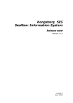
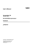
Figure 12 displays the four task states and how the tasks transition between them.
Task_create()
Task is created
Task_Mode_READY
Task runs
Task_delete()
Task is deleted
Semaphore_post(), ...
Task is readied
Task_yield()
Task is preempted
Task_Mode_RUNNING
Task_exit()
Task exits
Task_Mode_TERMINATED
Task_sleep(),
Semaphore_pend(), ...
Task suspends
Task_Mode_BLOCKED
Figure 12. Task State Diagram
Find more information about the SYS/BIOS tasks in the SYS/BIOS User’s Manual in the SYS/BIOS
section of the Help Contents found in the Help > Help Contents menu of Code Composer Studio.
2.6
Synchronization Modules
The SYS/BIOS kernel provides several different modules for synchronizing tasks within the system. These
include semaphores, gates, events, and mailboxes.
Semaphores are typically used to protect a hardware resource that is accessed by multiple tasks. Using a
semaphore ensures that the task that is accessing the hardware resource completes its action before
allowing another task to take control of the resource. An example of an application where a semaphore is
useful is when multiple tasks need to write data to a UART interface. Interrupting a task when the task is
in the middle of printing a message generates a jumbled message on the output terminal.
Gates are similar to semaphores but are typically used to protect shared sections of software as opposed
to hardware resources. There are multiple types of pre-defined gates that can be used or user-defined
gates can be created. For example, a gate would be used to protect the writing of a global variable to
ensure that the variable is assigned a valid value by one task before another is allowed to access it.
Events are another specific implementation of a semaphore. They require that several conditions exist
before a pending thread returns from a pend call. Note that only a single task can pend on an event at a
time. In the case of the UART example mentioned above, the second task may want to ensure that the
write buffer of the UART module is clear before the task begins writing data to the UART. The task would
set up an event to check the UART write buffer before pending on the semaphore.
Mailboxes are used to pass data buffers between tasks. Events can be associated with mailboxes to allow
for additional synchronization. Mailboxes can be used to ensure that the flow of incoming buffers does not
exceed the ability of the system to process those buffers.
For the purpose of this document, only semaphores are covered in detail. Additional information about
other synchronization modules can be found in the SYS/BIOS User’s Manual in the SYS/BIOS section of
the Help Contents found in the Help > Help Contents menu of Code Composer Studio.
Semaphores are used to protect resources that must complete a required operation within one task before
switching control to another task. There are two types of semaphores in SYS/BIOS:
• Binary semaphores
• Counting semaphores
SPMA040A – January 2012 – Revised November 2012
Submit Documentation Feedback
Using SYS/BIOS With Stellaris® ARM® Cortex™-M3 Microcontrollers
Copyright © 2012, Texas Instruments Incorporated
11
Overview of SYS/BIOS
www.ti.com
Binary semaphores are typically used for resources that are either in use or available. Counting
semaphores allow a resource to be accessed by multiple tasks before restricting access to the resource. A
count of zero is the lowest possible value for a semaphore and indicates that the resource is not available.
Posting to a semaphore increments its count while pending on a semaphore decrements its count.
Calling semaphore_post(mySem) on a semaphore mySem with a count of one results in:
• A count of 2 on a counting semaphore
• A count of 1 on a binary semaphore
The following examples and figures show the operation of semaphores.
If a task is running and calls the Semaphore_pend( ) function (that is, decrements the count of the
semaphore) on a semaphore with a count of 2, the task continues to run as show in Figure 13.
myTask
myTask
Semaphore_pend (mySem);
(RUNNING)
(RUNNING)
mySem
mySem
2
1
Figure 13. Task Continues to Run After Semaphore_Pend()
However, if a task is running and the task calls the Semaphore_pend( ) function on a semaphore with a
count of 0, the task blocks as shown in Figure 14.
myTask
myTask
Semaphore_pend (mySem);
(RUNNING)
(BLOCKED)
mySem
mySem
0
0
Figure 14. Blocking a Task With a Semaphore
To unblock the task, another task must call the semaphore_post( ) function to increment the count of the
semaphore. In the example in Figure 15, the lower priority task posts the semaphore to indicate that the
task no longer requires access to the restricted resource. The higher priority task is then switched from the
blocked to the running state because the task was waiting for this resource to become available. As soon
as the task starts running, the task pends on the semaphore to notify the program that the task is now
using the resource controlled by the semaphore.
12
Using SYS/BIOS With Stellaris® ARM® Cortex™-M3 Microcontrollers
SPMA040A – January 2012 – Revised November 2012
Submit Documentation Feedback
Copyright © 2012, Texas Instruments Incorporated
Overview of SYS/BIOS
www.ti.com
myLowPriTask
Semaphore_post (mySem);
myLowPriTask
(RUNNING)
myHiPriTask
(READY)
myHiPriTask
Semaphore_pend (mySem);
(BLOCKED)
(RUNNING)
mySem
mySem
0
0
Figure 15. Unblocking a Task With a Semaphore
Note that in the SYS/BIOS kernel, the first task in the semaphore queue (not necessarily the higher priority
task) is the first to unblock. This means that the first task that blocked is the first one that will be made
ready to run when the semaphore is posted. Another important note is the fact that multiple tasks can
block on the same semaphore (as Figure 16 illustrates), where both the high and medium priority tasks
are waiting on the same semaphore. Since the medium priority task was the first to pend on the
semaphore, the medium priority task is allowed to execute before the higher priority task. This type of
priority inversion can be prevented with the use of a specific type of gate called a GateMutexPri.
lowPriTask
lowPriTask
Semaphore_post (mySem);
(READY)
(RUNNING)
medPriTask
medPriTask
Semaphore_pend (mySem);
(BLOCKED)
hiPriTask
(RUNNING)
hiPriTask
Semaphore_pend (mySem);
(BLOCKED)
(BLOCKED)
mySem
mySem
0
0
Figure 16. Unblocking a Task With a Semaphore When Multiple Tasks Are Blocked
Find more information about the SYS/BIOS semaphores in the SYS/BIOS User’s Manual in the SYS/BIOS
section of the Help Contents found in the Help > Help Contents menu of Code Composer Studio.
SPMA040A – January 2012 – Revised November 2012
Submit Documentation Feedback
Using SYS/BIOS With Stellaris® ARM® Cortex™-M3 Microcontrollers
Copyright © 2012, Texas Instruments Incorporated
13
Overview of SYS/BIOS
2.7
www.ti.com
Timers and Clocks
Timers and clocks can be configured within SYS/BIOS to maintain portability between TI microcontrollers.
When the SYS/BIOS timer module is used, the kernel manages the hardware timer peripherals on the
device. Timer threads are run within the context of a HWI thread.
The SYS/BIOS clock module layers on top of the timer modules and manages the RTOS time base. The
clock module allows functions to be fired as one-shot timers or periodically using the functionality and
priority of a software interrupt (SWI). Clocks run at the same SWI priority so they cannot preempt each
other.
In the case of the Stellaris Cortex-M3, the SysTick timer in the core can be used as the RTOS time base
by adding the following lines into the configuration file:
var halTimer = xdc.useModule('ti.sysbios.hal.Timer');
halTimer.TimerProxy = xdc.useModule('ti.sysbios.family.arm.m3.Timer');
More information about using specific Cortex-M3 timers in a SYS/BIOS application can be found on the
SYS/BIOS for Stellaris Devices Wiki page.
In addition to the timer and clock module, a timestamp module is provided as a component of the
SYS/BIOS architecture. This module is useful for benchmarking applications that require precise timing
measurements.
Find more information about the SYS/BIOS timers and clocks in the SYS/BIOS User’s Manual in the
SYS/BIOS section of the Help Contents found in the Help > Help Contents menu of Code Composer
Studio.
14
Using SYS/BIOS With Stellaris® ARM® Cortex™-M3 Microcontrollers
SPMA040A – January 2012 – Revised November 2012
Submit Documentation Feedback
Copyright © 2012, Texas Instruments Incorporated
Overview of SYS/BIOS
www.ti.com
2.8
Debugging Tools
The process of debugging a real time system requires additional real-time analysis tools because of the
latency that is introduced into the system with a traditional debugger. SYS/BIOS provides several tools
and features including:
• Asserts
• Logging in application and RTOS
• Real-time analysis
Asserts check for common user mistakes such as calling an API with an invalid argument or from an
unsupported context. Logging prints important events in both the application and the RTOS to a terminal
for debugging timing issues in a system. Real-time analysis streams debugging data to the host without
stopping the processor.
An important feature to note about the SYS/BIOS debugging tools is that the log and trace information is
formatted on the host computer so that the application processor can continue to execute code with
minimal to no interference.
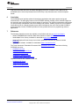
To access the SYS/BIOS real-time analysis (RTA) tools, make sure CCS is in the debug perspective.
Then, navigate to the Tools > RTA menu option to see the available RTA tools. Figure 17 displays the
available RTA tools.
Figure 17. Real-Time Analysis Tools
In addition to the RTA tools, the Runtime Object Viewer (ROV) can analyze a SYS/BIOS system. This tool
contains a list of the modules used in the program and displays detailed information about the selected
module. For example, if the task module is selected, the mode, arguments, stack size, and other attributes
of each of the tasks are updated when the program is paused or a breakpoint is encountered.
Find more information about the SYS/BIOS debugging tools in the SYS/BIOS User’s Manual in the
SYS/BIOS section of the Help Contents found in the Help > Help Contents menu of Code Composer
Studio.
SPMA040A – January 2012 – Revised November 2012
Submit Documentation Feedback
Using SYS/BIOS With Stellaris® ARM® Cortex™-M3 Microcontrollers
Copyright © 2012, Texas Instruments Incorporated
15
Downloading SYS/BIOS
3
www.ti.com
Downloading SYS/BIOS
SYS/BIOS is provided as part of Texas Instruments’ Code Composer Studio (CCS) Integrated
Development Environment (IDE). SYS/BIOS can also be downloaded as a stand-alone component, but
this download process is not explained in this document. For more information about the stand-alone
component, visit the SYS/BIOS Wiki.
Download the latest version of CCS from the Texas Instruments Embedded Processors Wiki. Note that
the code size limited version of CCS does not include SYS/BIOS, so you must download the full DVD
versions.
For the purpose of this document, CCS version 4.2.4.00033 was used. Different versions of CCS can be
used but may contain slightly different features.
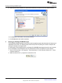
To download and install Code Composer Studio:
1. Go to http://processors.wiki.ti.com/index.php/Download_CCS
2. Click the Download button for the latest production CCSv4 DVD image
3. Click the Download button to download the .zip file.
4.
5.
6.
7.
16
Save the .zip file.
Extract the .zip file.
Run setup_CCS_x.x.x.x.exe.
You can use the default installation settings or only install the required components for the Stellaris
family of devices (Stellaris Cortex-M3 CPUs and ARM).
Note: This screen lists the CCS packages that are not yet installed, so the screen may look different.
Using SYS/BIOS With Stellaris® ARM® Cortex™-M3 Microcontrollers
SPMA040A – January 2012 – Revised November 2012
Submit Documentation Feedback
Copyright © 2012, Texas Instruments Incorporated
Downloading SYS/BIOS
www.ti.com
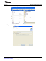
8. Click Next.
SPMA040A – January 2012 – Revised November 2012
Submit Documentation Feedback
Using SYS/BIOS With Stellaris® ARM® Cortex™-M3 Microcontrollers
Copyright © 2012, Texas Instruments Incorporated
17
Running an Existing SYS/BIOS Project
www.ti.com
9. Make sure that the DSP/BIOS 6.x and XDCtools boxes are checked on the next installer window.
10. Click Next and CCS installs to the selected directory.
11. Click Finish when the installer completes.
4
Running an Existing SYS/BIOS Project
The SYS/BOIS software package comes with several examples programs that showcase the features and
capabilities of the kernel. The following steps outline the process of opening one of these examples and
running the example on a target device.
For the purpose of the example project, the Stellaris DK-LM3S9B96 development board is used. However,
any of the Stellaris Cortex-M3 devices can be substituted and used as the platform for this example.
1. Launch CCS from Start > All Programs > Texas Instruments > Code Composer Studio v4.2.x > Code
Composer Studio v4.
2. Make sure that the C/C++ perspective is selected in CCS.
18
Using SYS/BIOS With Stellaris® ARM® Cortex™-M3 Microcontrollers
SPMA040A – January 2012 – Revised November 2012
Submit Documentation Feedback
Copyright © 2012, Texas Instruments Incorporated
Running an Existing SYS/BIOS Project
www.ti.com
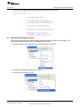
3. Select File > New > CCS Project.
4. Type a name for the project in the Project name: field.
SPMA040A – January 2012 – Revised November 2012
Submit Documentation Feedback
Using SYS/BIOS With Stellaris® ARM® Cortex™-M3 Microcontrollers
Copyright © 2012, Texas Instruments Incorporated
19
Running an Existing SYS/BIOS Project
www.ti.com
5. Click Next. Confirm that the ARM option is selected in the Project Type: drop-down menu.
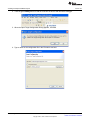
6. Click Next. In this case, there will not be any referenced projects, so leave all project boxes unchecked
if any appear in the Referenced Projects field.
20
Using SYS/BIOS With Stellaris® ARM® Cortex™-M3 Microcontrollers
SPMA040A – January 2012 – Revised November 2012
Submit Documentation Feedback
Copyright © 2012, Texas Instruments Incorporated
Running an Existing SYS/BIOS Project
www.ti.com
7. Click Next. Select Cortex M from the left Device Variant: drop-down menu. Select the Stellaris device
you are using from the drop-down menu to the right of the Cortex M selection.
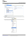
8. Click Next. Under the SYS/BIOS folder, select Generic Examples. Clicking each of the examples
displays an explanation of the example in the right-hand window. Select the Log Example.
SPMA040A – January 2012 – Revised November 2012
Submit Documentation Feedback
Using SYS/BIOS With Stellaris® ARM® Cortex™-M3 Microcontrollers
Copyright © 2012, Texas Instruments Incorporated
21
Creating a Sample SYS/BIOS Project
www.ti.com
9. Click Next. Make sure that the SYS/BIOS box is checked in the main window. Also, select the
appropriate platform from the Platform: drop-down menu.
10. Click Finish.
11. After the project is loaded, the project can be built and debugged. (See Section 5.3, Building and
Debugging a Project.) The log example showcases the features of the Raw Logs and Printf Logs RealTime Analysis (RTA) Tools. (See Section 2.8, Debugging Tools.)
5
Creating a Sample SYS/BIOS Project
Creating a new SYS/BIOS project is easily done with the use of the provided project templates. There are
three types of templates:
• Minimal
• Typical
• Typical with a separate configuration project
The minimal template is used for applications that use only statically defined objects. Dynamic memory
allocation is disabled to improve the code size and performance of the system. The template opens with a
single task function consisting of several printf ( ) statements and a call to the Task_sleep( ) function.
The typical template is a common starting place for most SYS/BIOS applications. Unlike the minimal
template, the typical template enables dynamic memory allocation which allows tasks to be created at
runtime instead of statically defined at compile time. In fact, the example project opens with a call to the
Task_create ( ) function in order to define the single default task.
The typical template with a separate configuration template creates a typical project in addition to a
second project that contains the configuration file for the first project. Multiple projects can now reference
the single configuration project for their SYS/BIOS settings thereby reducing build times and allowing
several developers to use a uniform configuration.
For the purpose of the example project listed below, the Stellaris DK-LM3S9B96 development board is
used. However, any of the Stellaris Cortex-M3 devices can be substituted and used as the platform for this
example.
22
Using SYS/BIOS With Stellaris® ARM® Cortex™-M3 Microcontrollers
SPMA040A – January 2012 – Revised November 2012
Submit Documentation Feedback
Copyright © 2012, Texas Instruments Incorporated
Creating a Sample SYS/BIOS Project
www.ti.com
5.1
Creating a New Project
This section describes how to load a project template into the workspace.
1. Launch CCS from Start > All Programs > Texas Instruments > Code Composer Studio v4.2.x > Code
Composer Studio v4.
2. Make sure that the C/C++ perspective is selected in CCS.
3. Select File > New > CCS Project.
4. Type a name for the project in the Project name: field.
SPMA040A – January 2012 – Revised November 2012
Submit Documentation Feedback
Using SYS/BIOS With Stellaris® ARM® Cortex™-M3 Microcontrollers
Copyright © 2012, Texas Instruments Incorporated
23
Creating a Sample SYS/BIOS Project
www.ti.com
5. Click Next. Confirm that the ARM option is selected in the Project Type: drop-down menu.
6. Click Next. In this case, there will not be any referenced projects, so leave all project boxes unchecked
if any appear in the Referenced Projects field.
24
Using SYS/BIOS With Stellaris® ARM® Cortex™-M3 Microcontrollers
SPMA040A – January 2012 – Revised November 2012
Submit Documentation Feedback
Copyright © 2012, Texas Instruments Incorporated
Creating a Sample SYS/BIOS Project
www.ti.com
7. Click Next. Select Cortex M from the left Device Variant: drop-down menu. Select the Stellaris device
you are using from the drop-down menu to the right of the Cortex M selection.
8. Click Next. Under the SYS/BIOS folder, select the new project type you would like to use (minimal,
typical, or typical with a separate config project). These options are explained earlier in this section
(see Section 5, Creating a Sample SYS/BIOS Project). Choose Typical for this example project.
SPMA040A – January 2012 – Revised November 2012
Submit Documentation Feedback
Using SYS/BIOS With Stellaris® ARM® Cortex™-M3 Microcontrollers
Copyright © 2012, Texas Instruments Incorporated
25
Creating a Sample SYS/BIOS Project
www.ti.com
9. Click Next. Select the appropriate platform from the Platform: drop-down menu.
10. Click Finish.
11. Since we are using the StellarisWare library to access the GPIO peripheral, you must add driverlib to
the project by following the steps provided in Section 5, Creating a Sample SYS/BIOS Project.
12. To begin editing the properties of the program, expand the project folder, right-click the app.cfg file,
and select Open With > XGCONF. The main GUI editor opens. From here, the settings of the
SYS/BIOS kernel can be modified. See Section 2.1, Configuration Tools, for more information about
configuring the system.
26
Using SYS/BIOS With Stellaris® ARM® Cortex™-M3 Microcontrollers
SPMA040A – January 2012 – Revised November 2012
Submit Documentation Feedback
Copyright © 2012, Texas Instruments Incorporated
Creating a Sample SYS/BIOS Project
www.ti.com
13. Create a new task by right-clicking Task and selecting New Task.
SPMA040A – January 2012 – Revised November 2012
Submit Documentation Feedback
Using SYS/BIOS With Stellaris® ARM® Cortex™-M3 Microcontrollers
Copyright © 2012, Texas Instruments Incorporated
27
Creating a Sample SYS/BIOS Project
www.ti.com
14. Edit the fields of the new task instance as shown. Click OK.
15. Add a second task instance by following the same method. Click OK.
28
Using SYS/BIOS With Stellaris® ARM® Cortex™-M3 Microcontrollers
SPMA040A – January 2012 – Revised November 2012
Submit Documentation Feedback
Copyright © 2012, Texas Instruments Incorporated
Creating a Sample SYS/BIOS Project
www.ti.com
16. Create a new semaphore by right-clicking Semaphore and selecting New Semaphore.
17. Edit the fields of the new semaphore instance as shown. Click OK.
SPMA040A – January 2012 – Revised November 2012
Submit Documentation Feedback
Using SYS/BIOS With Stellaris® ARM® Cortex™-M3 Microcontrollers
Copyright © 2012, Texas Instruments Incorporated
29
Creating a Sample SYS/BIOS Project
www.ti.com
18. Add the Agent module to enable the real-time analysis tools for debugging.
19. Modify the main.c file to look like the following text.
/*
* ======== main.c ========
*/
#include <xdc/std.h>
#include <xdc/runtime/Error.h>
#include <xdc/runtime/System.h>
#include <xdc/runtime/Log.h>
#include <ti/sysbios/BIOS.h>
#include <ti/sysbios/knl/Task.h>
#include <ti/sysbios/knl/Semaphore.h>
#include
#include
#include
#include
#include
"inc/hw_types.h"
"inc/hw_memmap.h"
"inc/lm3s9b96.h"
"driverlib/sysctl.h"
"driverlib/gpio.h"
extern Semaphore_Handle sem;
/*
* ======== Task Functions ========
*/
Void toggle_low_freq()
{
while(1){
Log_info0("toggle_low_freq() enter");
//Pend on the semaphore
Log_info0("toggle_low_freq() pend sem");
Semaphore_pend(sem, BIOS_WAIT_FOREVER);
//Set the value of the GPIO pin low
Log_info0("toggle_low_freq() pin low");
GPIOPinWrite(GPIO_PORTA_BASE, GPIO_PIN_6, 0);
//Sleep
Log_info0("toggle_low_freq() sleep");
Task_sleep(10);
30
Using SYS/BIOS With Stellaris® ARM® Cortex™-M3 Microcontrollers
SPMA040A – January 2012 – Revised November 2012
Submit Documentation Feedback
Copyright © 2012, Texas Instruments Incorporated
Creating a Sample SYS/BIOS Project
www.ti.com
//Post to the semaphore
Log_info0("toggle_low_freq() post sem");
Semaphore_post(sem);
//Sleep
Log_info0("toggle_low_freq() sleep");
Task_sleep(10);
Log_info0("toggle_low_freq() exit");
}
}
Void toggle_high_freq()
{
while(1){
Log_info0("toggle_high_freq() enter");
//Pend on the semaphore
Log_info0("toggle_high_freq() pend sem");
Semaphore_pend(sem, BIOS_WAIT_FOREVER);
//Set the value of the GPIO pin low
Log_info0("toggle_high_freq() pin low");
GPIOPinWrite(GPIO_PORTA_BASE, GPIO_PIN_6, 0);
//Sleep
Log_info0("toggle_high_freq() sleep");
Task_sleep(1);
//Set the value of the GPIO pin high
Log_info0("toggle_high_freq() pin high");
GPIOPinWrite(GPIO_PORTA_BASE, GPIO_PIN_6, GPIO_PIN_6);
//Post to the semaphore
Log_info0("toggle_high_freq() post sem");
Semaphore_post(sem);
//Sleep
Log_info0("toggle_high_freq() sleep");
Task_sleep(1);
Log_info0("toggle_high_freq() exit");
}
}
/*
* ======== main ========
*/
Void main()
{
Log_info0("enter main()");
//Enable and configure the GPIO peripheral
SysCtlPeripheralEnable(SYSCTL_PERIPH_GPIOA);
GPIOPinTypeGPIOOutput(GPIO_PORTA_BASE, GPIO_PIN_6);
//Initialize GPIO pin PA6 to a value of 0
GPIOPinWrite(GPIO_PORTA_BASE, GPIO_PIN_6, 0);
//Start the BIOS scheduler
BIOS_start(); /* enable interrupts and start SYS/BIOS */
}
20. Save the project using File > Save All from the menu.
SPMA040A – January 2012 – Revised November 2012
Submit Documentation Feedback
Using SYS/BIOS With Stellaris® ARM® Cortex™-M3 Microcontrollers
Copyright © 2012, Texas Instruments Incorporated
31
Creating a Sample SYS/BIOS Project
5.2
www.ti.com
Integrating StellarisWare Libraries
StellarisWare is a software package provided for use with Stellaris microcontrollers that enables the use of
API functions located in the read-only memory (ROM) of most Stellaris devices. Note that not all
StellarisWare functions are inherently thread-safe. In other words, having a higher-priority task call a
function after the first task has started executing the function may cause unexpected failures in the
system. To remedy these types of situations, those functions that are not thread-safe and are called from
more than one context should be protected with the use of semaphores or gates.
The following steps outline the process of linking the driverlib API library into a SYS/BIOS project. The
process should be repeated to incorporate the usblib (USB) and grlib (graphics) libraries. If your project
does not include calls to the StellarisWare libraries, you can skip this section and go to Section 5.3,
Building and Debugging a Project.
1. Right-click the name of your project and select Build Properties.
32
Using SYS/BIOS With Stellaris® ARM® Cortex™-M3 Microcontrollers
SPMA040A – January 2012 – Revised November 2012
Submit Documentation Feedback
Copyright © 2012, Texas Instruments Incorporated
Creating a Sample SYS/BIOS Project
www.ti.com
2. Click the Include Options folder under the TIMS470 Compiler folder in the folder tree on the Tool
Settings tab. Click the Add button in the lower box that appears on the right-hand side of the screen.
3. Type C:\StellarisWare into the Directory: field in the Add directory path dialog box. Click OK.
SPMA040A – January 2012 – Revised November 2012
Submit Documentation Feedback
Using SYS/BIOS With Stellaris® ARM® Cortex™-M3 Microcontrollers
Copyright © 2012, Texas Instruments Incorporated
33
Creating a Sample SYS/BIOS Project
www.ti.com
4. Click the File Search Path folder under the TMS470 Linker folder in the folder tree on the Tool
Settings tab. Click the Add button in the upper box that appears on the right-hand side of the screen.
5. Type C:\StellarisWare\driverlib\ccs-cm3\Debug\driverlib-cm3.lib into the File: field in the Add file path
dialog box.
6. Click OK in the Properties window.
34
Using SYS/BIOS With Stellaris® ARM® Cortex™-M3 Microcontrollers
SPMA040A – January 2012 – Revised November 2012
Submit Documentation Feedback
Copyright © 2012, Texas Instruments Incorporated
Creating a Sample SYS/BIOS Project
www.ti.com
7. In the main.c file, add the following include statements to the top of the code:
#include "inc/hw_types.h"
#include "driverlib/sysctl.h"
5.3
Building and Debugging a Project
This section outlines the steps required to build a project and launch the project in the debugger. This
section also highlights several of the key SYS/BIOS diagnostic tools.
1. Build the project by right-clicking the project and selecting Rebuild Project.
2. Connect the LM3S9B96 development kit to the PC.
3. Set the project as the Active Project.
SPMA040A – January 2012 – Revised November 2012
Submit Documentation Feedback
Using SYS/BIOS With Stellaris® ARM® Cortex™-M3 Microcontrollers
Copyright © 2012, Texas Instruments Incorporated
35
Creating a Sample SYS/BIOS Project
www.ti.com
4. Click the green Debug button to load the code into the device and launch the debugger.
5. When the Open Target Configuration Dialog appears, click Yes.
6. Type a name for the configuration file in the File name: text field.
36
Using SYS/BIOS With Stellaris® ARM® Cortex™-M3 Microcontrollers
SPMA040A – January 2012 – Revised November 2012
Submit Documentation Feedback
Copyright © 2012, Texas Instruments Incorporated
Creating a Sample SYS/BIOS Project
www.ti.com
7. Select Stellaris In-Circuit Debug Interface in the Connection drop-down menu. Select your device from
the Device window.
8. Click Save.
9. If the CCS Debug perspective does not launch automatically, change the perspective by clicking
Debug in the top right-hand corner of the screen.
10. Go to Tools > ROV to open the Runtime Object Viewer. This tool provides information about the
SYS/BIOS modules when the target is halted.
SPMA040A – January 2012 – Revised November 2012
Submit Documentation Feedback
Using SYS/BIOS With Stellaris® ARM® Cortex™-M3 Microcontrollers
Copyright © 2012, Texas Instruments Incorporated
37
Creating a Sample SYS/BIOS Project
www.ti.com
11. Set a breakpoint in each of the tasks as shown.
12. Run the debugger.
38
Using SYS/BIOS With Stellaris® ARM® Cortex™-M3 Microcontrollers
SPMA040A – January 2012 – Revised November 2012
Submit Documentation Feedback
Copyright © 2012, Texas Instruments Incorporated
Creating a Sample SYS/BIOS Project
www.ti.com
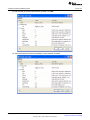
13. When the target halts at the first breakpoint, open the ROV tool and observe the task details. The
state of each task is displayed along with other details about each task.
14. Explore the options available within the ROV Tool.
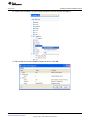
15. Go to Tools > RTA > Exec Graph to open one of the Real-Time Analysis Tools. The RTA tools provide
diagnostic information about the system execution including logs, execution graphs, and load data.
SPMA040A – January 2012 – Revised November 2012
Submit Documentation Feedback
Using SYS/BIOS With Stellaris® ARM® Cortex™-M3 Microcontrollers
Copyright © 2012, Texas Instruments Incorporated
39
Creating a Sample SYS/BIOS Project
www.ti.com
16. In order to bypass the breakpoints placed in the code for the ROV tool, Select Free Run from the
drop-down option next to the Run button.
17. At this point, the following output should appear on GPIO pin PA6 of the development board. The
high-frequency oscillations are created with the toggle_high_freq task while the lower frequency square
wave envelope is created by the toggle_low_freq task.
18. Halt the target.
19. Observe the output in the Exec Graph window.
20. Explore the options available within the RTA Exec Graph Tool.
40
Using SYS/BIOS With Stellaris® ARM® Cortex™-M3 Microcontrollers
SPMA040A – January 2012 – Revised November 2012
Submit Documentation Feedback
Copyright © 2012, Texas Instruments Incorporated
Conclusion
www.ti.com
Find more information about the SYS/BIOS debugging tools in the SYS/BIOS User’s Manual in the
SYS/BIOS section of the Help Contents found in the Help > Help Contents menu of Code Composer
Studio.
6
Conclusion
The SYS/BIOS kernel provides a basis for developing applications that require precise timing and
instrumentation. The debugging features of the SYS/BIOS software package provide valuable insight into
the execution state of the program at various stages of execution. The graphical configuration utility allows
for quick and easy manipulation of the kernel settings and modules. Creating a project to run on Stellaris
Cortex-M3 devices is a straight-forward process that is facilitated by the use of the provided SYS/BIOS
project templates. Overall, SYS/BIOS provides a robust, portable structure for programming real-time
applications.
7
References
The following related documents are available on the Stellaris web site at www.ti.com/stellaris:
• Stellaris LM3S9B96 Microcontroller Data Sheet (literature number SPMS182)
• StellarisWare Driver Library. Available for download at www.ti.com/tool/sw-drl.
• Stellaris® Peripheral Driver Library User’s Guide, publication SW-DRL-UG (literature number
SPMU019).
• StellarisWare software. Available for download at www.ti.com/tool/sw-lm3s
The Texas Instruments’ Embedded Processors Wiki (processors.wiki.ti.com) contains the following
SYS/BIOS resources:
• SYS/BIOS Overview
• SYS/BIOS Getting Started Guide
• SYS/BIOS Online Training
• SYS/BIOS for Stellaris Devices
• SYS/BIOS Getting Started Workshop
Additional resources are available on the web:
• SYS/BIOS E2E Forum
• Stellaris Sizing Benchmark
• Stellaris Timing Benchmark
SPMA040A – January 2012 – Revised November 2012
Submit Documentation Feedback
Using SYS/BIOS With Stellaris® ARM® Cortex™-M3 Microcontrollers
Copyright © 2012, Texas Instruments Incorporated
41
IMPORTANT NOTICE
Texas Instruments Incorporated and its subsidiaries (TI) reserve the right to make corrections, enhancements, improvements and other
changes to its semiconductor products and services per JESD46, latest issue, and to discontinue any product or service per JESD48, latest
issue. Buyers should obtain the latest relevant information before placing orders and should verify that such information is current and
complete. All semiconductor products (also referred to herein as “components”) are sold subject to TI’s terms and conditions of sale
supplied at the time of order acknowledgment.
TI warrants performance of its components to the specifications applicable at the time of sale, in accordance with the warranty in TI’s terms
and conditions of sale of semiconductor products. Testing and other quality control techniques are used to the extent TI deems necessary
to support this warranty. Except where mandated by applicable law, testing of all parameters of each component is not necessarily
performed.
TI assumes no liability for applications assistance or the design of Buyers’ products. Buyers are responsible for their products and
applications using TI components. To minimize the risks associated with Buyers’ products and applications, Buyers should provide
adequate design and operating safeguards.
TI does not warrant or represent that any license, either express or implied, is granted under any patent right, copyright, mask work right, or
other intellectual property right relating to any combination, machine, or process in which TI components or services are used. Information
published by TI regarding third-party products or services does not constitute a license to use such products or services or a warranty or
endorsement thereof. Use of such information may require a license from a third party under the patents or other intellectual property of the
third party, or a license from TI under the patents or other intellectual property of TI.
Reproduction of significant portions of TI information in TI data books or data sheets is permissible only if reproduction is without alteration
and is accompanied by all associated warranties, conditions, limitations, and notices. TI is not responsible or liable for such altered
documentation. Information of third parties may be subject to additional restrictions.
Resale of TI components or services with statements different from or beyond the parameters stated by TI for that component or service
voids all express and any implied warranties for the associated TI component or service and is an unfair and deceptive business practice.
TI is not responsible or liable for any such statements.
Buyer acknowledges and agrees that it is solely responsible for compliance with all legal, regulatory and safety-related requirements
concerning its products, and any use of TI components in its applications, notwithstanding any applications-related information or support
that may be provided by TI. Buyer represents and agrees that it has all the necessary expertise to create and implement safeguards which
anticipate dangerous consequences of failures, monitor failures and their consequences, lessen the likelihood of failures that might cause
harm and take appropriate remedial actions. Buyer will fully indemnify TI and its representatives against any damages arising out of the use
of any TI components in safety-critical applications.
In some cases, TI components may be promoted specifically to facilitate safety-related applications. With such components, TI’s goal is to
help enable customers to design and create their own end-product solutions that meet applicable functional safety standards and
requirements. Nonetheless, such components are subject to these terms.
No TI components are authorized for use in FDA Class III (or similar life-critical medical equipment) unless authorized officers of the parties
have executed a special agreement specifically governing such use.
Only those TI components which TI has specifically designated as military grade or “enhanced plastic” are designed and intended for use in
military/aerospace applications or environments. Buyer acknowledges and agrees that any military or aerospace use of TI components
which have not been so designated is solely at the Buyer's risk, and that Buyer is solely responsible for compliance with all legal and
regulatory requirements in connection with such use.
TI has specifically designated certain components as meeting ISO/TS16949 requirements, mainly for automotive use. In any case of use of
non-designated products, TI will not be responsible for any failure to meet ISO/TS16949.
Products
Applications
Audio
www.ti.com/audio
Automotive and Transportation
www.ti.com/automotive
Amplifiers
amplifier.ti.com
Communications and Telecom
www.ti.com/communications
Data Converters
dataconverter.ti.com
Computers and Peripherals
www.ti.com/computers
DLP® Products
www.dlp.com
Consumer Electronics
www.ti.com/consumer-apps
DSP
dsp.ti.com
Energy and Lighting
www.ti.com/energy
Clocks and Timers
www.ti.com/clocks
Industrial
www.ti.com/industrial
Interface
interface.ti.com
Medical
www.ti.com/medical
Logic
logic.ti.com
Security
www.ti.com/security
Power Mgmt
power.ti.com
Space, Avionics and Defense
www.ti.com/space-avionics-defense
Microcontrollers
microcontroller.ti.com
Video and Imaging
www.ti.com/video
RFID
www.ti-rfid.com
OMAP Applications Processors
www.ti.com/omap
TI E2E Community
e2e.ti.com
Wireless Connectivity
www.ti.com/wirelessconnectivity
Mailing Address: Texas Instruments, Post Office Box 655303, Dallas, Texas 75265
Copyright © 2012, Texas Instruments Incorporated