1
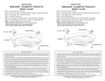
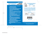
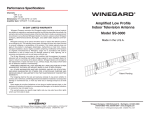
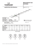
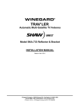
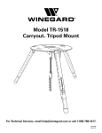
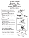
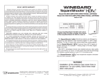
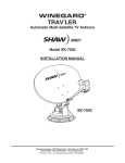
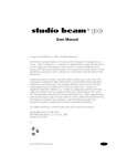
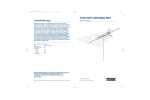
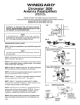
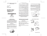
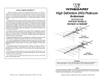
WARNING:
INSTALLATION OF ANTENNAS NEAR POWER LINES IS DANGEROUS.
FOR YOUR SAFETY, FOLLOW THE INSTALLATION INSTRUCTIONS.
INSTALLATION
This SENSAR antenna may be installed inside or outside on any mast or
pole. DO NOT MOUNT OVER CHIMNEY OPENING.
STEP 1. Make sure "W" opening is on bottom side of antenna head, foot
embossing points down. Slide metal mounting bracket up into back bracket
on antenna and attach with pins and E-clips. See Figure 1.
STEP 2. Insert "U" bolt thru mast clamp and mast bracket and start hex
nuts onto "U" bolt. See Figure 1.
STEP 3. Slide mast thru "U" bolt and tighten hex nuts with 7/16" wrench.
Model GS-1100, VM-1100 (Non-amplified Models ONLY)
Attaching Downlead Cable
STEP 1. Attach downlead cable to F-jack on back of antenna head and
tighten securely. (Figure 4). Tape downlead to mast and run cable to TV.
STEP 2. Attach "F" connector to downlead and connect to "F" jack on TV.
(2) Pin
Models GS-2200, VM-2200
(Amplified Models ONLY)
Attaching Downlead Cable
STEP 1. Attach downlead cable to Fjack on back of antenna head and
tighten securely. (Figure 4) Tape
downlead to mast and run cable to
power supply location.
STEP 2. Attach "F" connector to
downlead and connect to "F" jack on
power supply marked "TO PREAMP".
See Figure 2.
STEP 3. Attach "F" connector to cable
from TV and connect to "F" jack on
power supply marked "TO TV". See
Figure 2.
STEP 4. Mount the two #6 screws
vertically 3-1/4" apart leaving screw
heads approximately 1/8" from wall.
See Figure 3.
STEP 5. Hang power supply onto
screws and plug power supply AC
power cord into receptacle.
(2) E-Clip
Mast Bracket
(2) Hex Nut
U-Bolt
Figure 4
NOTICE: FAILURE TO PROPERLELY CONNECT
CABLES MAY RESULT IN DAMGE TO TV SET.
TO TV
TO PREAMP
Figure 2
U.S. Pat. No. D355,887,
D358,365, 5,515,240 Power
supply housing design.
#6x1/2
Screws
3-1/4"
Figure 3
Attach
coax here.
Mast Clamp
Figure 1
CAUTION: No splitters or coupler should be installed in the coax
line between the antenna and power supply.
90 DAY LIMITED WARRANTY
Winegard Company warrants this Winegard product against any defects in materials or workmanship within 90
(ninety) days from date of purchase. No warranty claim will be honored unless at the time the claim is made, you
present proof of purchase to an authorized Winegard dealer (if unknown, please contact Winegard Company, 3000
Kirkwood Street, Burlington, IA 52601-2000, Telephone 319-754-0600).
Winegard Company (at its option) will either repair or replace the defective product at no charge to you. This
warranty covers parts, but does not cover any costs incurred in removal, shipping or reinstallation of the product.
This limited warranty does not apply if the product is damaged, deteriorates, malfunctions or fails from: misuse,
improper installation, abuse, neglect, accident, tampering, modification of the product as originally manufactured
by Winegard, usage not in accordance with product instructions or acts of nature such as damage caused by wind,
lightning, ice or corrosive environments such as salt spray and acid rain.
The 90 Day Warranty is provided on the condition that the equipment is properly delivered with all handling and
freight charges prepaid to your Winegard dealer for return to our factory for repair or replacement. Winegard dealers
will arrange for the replacement or repair and return to you without charge the product which failed due to defective
material or workmanship.
WINEGARD®
SENSAR® TV ANTENNA
Amplified Model GS-2200, VM-2200
Non-amplified Model GS-1100, VM-1100
Made in U.S.A.
U.S. Patent No. D500,496
WINEGARD COMPANY WILL NOT ASSUME ANY LIABILITIES FOR ANY OTHER WARRANTIES, EXPRESS
OR IMPLIED, MADE BY ANY OTHER PERSON.
ALL OTHER WARRANTIES WHETHER EXPRESS, IMPLIED OR STATUTORY INCLUDING WARRANTIES OF
FITNESS FOR A PARTICULAR PURPOSE AND MERCHANTABILITY ARE LIMITED TO THE 90-DAY PERIOD OF
THIS WARRANTY.
The foregoing shall be the sole and exclusive remedy of any person, whether in contract, tort or otherwise, and
Winegard shall not be liable for incidental or consequential damage or commercial loss, or from any other loss or
damage except as set forth above.
Some states do not allow limitations on how long an implied warranty lasts, or the exclusion of limitation of
incidental or consequential damages, so the above limitations or exclusions may not apply to you.
This warranty gives you specific legal rights and you may also have other rights which vary from state to state.
HOW TO PROVIDE LIGHTNING
PROTECTION FOR TV ANTENNA
AND SET
Example of antenna grounding as per
National Electrical Code, ANSI/NFPA 70
STEP 1. Mount the lightning arrestor as
close as possible to where the downlead
enters the house.
STEP 2. The ground wires for both the mast
and the downlead should be copper or
aluminum wire, number eight (8) or larger.
STEP 3. The downlead wire from the
antenna to the lightning arrestor should be
secured every four (4) to six (6) feet to
prevent whipping.
NOTE: In the case of a "ground up" antenna
installation, it may not be necessary to
ground the mast if the mast extends four or
more feet into the ground. Consult a TV
serviceman for proper depth in your location.
WARNING: TO PREVENT FIRE
OR SHOCK HAZARD, DO NOT
EXPOSE POWER SUPPLY TO
RAIN OR MOISTURE.
Antenna Lead
In Wire
Ground
Clamp
Grounding Wire Conductors
(NEC Section 810-21)
Electric
Service
Equipment
Antenna
Discharge Unit
(NEC Section 810-20)
Ground
Clamps
WARNING: INSTALLATION OF
ANTENNAS NEAR POWER
LINES IS DANGEROUS. FOR
YOUR SAFETY, FOLLOW THE
INSTALLATION INSTRUCTIONS.
Rain Drip Loop On
Lead-In To TV
Power Service Grounding
Electrode System
(NEC Art 250, Part H)
NEC - National Electrical Code
Printed in U.S.A. © 2004,2005 Winegard Company 2452016 Rev. 01/05
NOTE: Any alteration or modification to product or any other use
of the parts other than their intended use, voids the warranty.
WINEGARD CO., 3000 KIRKWOOD STREET, BURLINGTON, IA 52601-2000