1
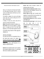
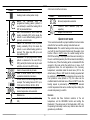
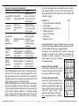
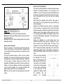
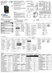
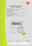
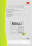
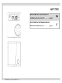
HRT-177RS
WIRELESS RF WEEKLY ROOM THERMOSTAT
Installation and user instruction……………page 2
CRONOTERMOSTATO SETTIMANALE SENZA FILI
Manuale di installazione e uso………….…pag. 11
WIRELESS - manual issue 02/2013 rev. 03
EN
IT
EN .
THESE INSTRUCTIONS ARE TO BE RETAINED BY THE USER
ENCODER KNOB: Encoder movements: clockwise and
anticlockwise rotation, push to select.
Encoder clockwise and anticlockwise rotation: increase or
decrease the room comfort temperature, auto enter of the
selected value after 5 seconds.
Encoder rotation one step: check the selected comfort
temperature. The value will blink for few times and later it will
be back to the room temperature value display.
Press and hold the encoder once to activate or de-activate
the ADVANCE function
Press and hold the encoder longer for enter in menu and
select
the
status
mode
or
set
the
time/programming/parameters (see specific paragraph).
Thank you for choosing this radio frequency (RF) radiostat.
This central heating control device is easy to fit, and with
correct use, will deliver improved comfort levels in your home
whilst saving you money.
This thermostat is designed to be used only with heating
controls system with a maximum switching load of 2A at
30VDC or 0,25A at 230VAC.
If installing for someone else, please ensure that the
instructions are handed to the householder.
WARNING: Please read this manual prior to installation or use.
SHOCK HAZARD: This unit must be installed by a competent
person, in accordance with BS 7671 (the IEE Wiring
Regulations), or other relevant national regulations and codes
of good practice. Always isolate the AC Mains supply before
installing this unit.
FIRST INSTALLATION WARNING .
DISPLAY
ENCODER
SENSOR
The product arrives with most of the parameters factory set
with minimal actions required by the installer: wiring
connections of the receiver to the boiler, setting the time and
setting the day. All the rest, like coupling between receiver and
transmitter, heating pattern, default temperatures, etc. are
already pre-configured at the factory.
OPENING
LCD DISPLAY
IMPORTANT: these instructions should be read in conjunction
with the appliance installation instructions. It is recommended
that this device is installed by a qualified electrician.
2
EN .
SYMBOL
other icons inside the main menu
DESCRIPTION/FUNCTION
STATUS MODE
Heating mode is active (winter mode)
SYMBOL
AUTO:
the
thermostat
uses
the
programmed heating pattern (default or
user defined) to switch the heating ON &
OFF at preselected times.
OFF: the thermostat is set to have the
heating constantly OFF (in this mode the
default or user defined heating pattern is
ignored) – summer mode.
PARTY: the thermostat is set to provide
heating constantly ON (in this mode the
default or user defined heating pattern is
ignored). This status stay ON up to end
user switching OFF
ADVANCE: the pre-programmed heating
pattern is advanced to the next ON (or
OFF) period (this function can only be used
when the clock is in the AUTO mode)
DESCRIPTION/FUNCTION
Economy temperature selection
Technical menu selection
expertise)
Escape from main menu
(only
for
QUICK START GUIDE
To be read and used after a proper installation has been made
and after the hours and the working mode has been set.
WORKING MODE: This central heating control device provides
you both the room thermostat function and the weekly clock
function. When in AUTO mode, the central heating will be
ON/OFF according to the programmed times and according to
the set comfort temperature (the ON command is identified by
the flame icon). When the heating will be commanded ON the
set-point in the room will be the comfort one. In case of off
programmed times, the set temperature is the “economy
temperature”, selectable inside the main menu (16°C is the
default value). When in OFF mode the heating requested will
be switched on when the room temperature drops under the
frost protection value (default is 5°C); this value can be
modified inside the technical menu. When in PARTY mode the
heating request is permanently on according the selected
comfort temperature that can be modified any time rotating the
encoder and pressing to confirm.
Used to show current day of week
Used to show current time of day or
explanation inside the main menu
24-hour clock in 60 minute segments. Side
example: The heating fascia is OFF up to
15:59 and it is ON from 16:00 to 18:59
Used to show current room temperature or
desired temperature to be selected.
Batteries low
ENCODER
The encoder has three functions: selection of the set
temperature, set the ADVANCE function and setting the
thermostat. If the status mode of the thermostat is OFF, only
the pressing functionality is active; any rotation done does not
generate any modification.
Heat request to the boiler (central heating
ON)
3
EN .
1. Rotate to select the desired temperature and press to enter.
2. Press once to activate or deactivate the ADVANCE function.
Use to “advance” the heating to an ON or OFF period
3. Press for 3 seconds to enter menu. Rotate to scroll through
the menu choosing between status mode, economy
temperature setting, time of day, day of the week,
programmed times day by day, technical menu (PL) and
exit. Press again to modify selected item.
Status mode: rotate to change the thermostat mode
between AUTO, PARTY, and OFF, press to save. The
press from status mode automatically escapes from menu.
Economy temperature ECOt: Rotate to select the desired
economy temperature and press to enter. This temperature
is used when programming time is OFF in AUTO status
mode.
Time of the day: rotate to change the hours, press to save.
Move to minutes; rotate to change minutes, press to save.
Day of the week: rotate to change the day, press to save
Programmed times day 1-7: rotate clockwise to set hour
ON, rotate anticlockwise to select hour OFF. Clockwise and
anticlockwise rotation move ahead the time. Press to save.
Rotate clockwise to move to the following day. It is possible
to program together days 1…5 and days 6-7 with the same
pattern in a single operation.
PL: rotate to select the password value, press to enter
inside the technical menu. Rotate to select the parameters:
01 = calibration of the temperature sensor, 02 = frost
protection temperature selection, 03 = hysteresis OFF value
selection, 04 = hysteresis ON value selection, 05 =
encoding and coupling with the RF receiver, 06 = radio
frequency value selection, EHIt = escape from technical
menu. (for technical menu see dedicated paragraph).
Exit: escape from main menu.
INSTALLATION AND OPERATING INSTRUCTIONS
Unlike the conventional thermostat, this control separates the
function in two units. The receiver serves for wiring
connections and heat on/off control. The transmitter serves as
the user interface and for temperature sensing/control. The
two units are linked by radio frequency (RF). The RF
communication is only in one direction from the transmitter to
the receiver, therefore the transmitter does not receive any
feedback from the receiver, no alarm of missing
communication is visible on the transmitter display.
THE TRANSMITTER is a wall-mounted
timer-thermostat. The transmitter can be
located wherever a conventional room
thermostat would normally be sited. No
wiring is required, as the transmitter is
battery powered.
THE RECEIVER is connected to the boiler,
and can replace a conventional
mechanical or electronic time clock. The
receiver arrives pre-cabled and ready to
be fixed, therefore it is not necessity to
open the receiver casing. The receiver is
equipped with a transparent bubble
button that incorporates the button
function, the green led function and the
red led function.
Button functions:
1. Press once: manually switch ON the heating (relay closed),
press again to switch OFF.
2. Press for 5 seconds: encoding procedure start up. After
success coupling there is an automatically exit from the
procedure.
4
EN .
Receiver led: colors and functionality
LED
FUNCTIONS
REASON
Signal received
Led green ON Relay closed =
from the transmitter
constantly
heating request ON or end user manual
button pressing
Signal received
Relay open =
Led red ON
from the transmitter
heating request
constantly
or end user manual
OFF
button pressing
The receiver button
Led green and
has been pressed
led red
Encoding procedure more than 5
blinking
working
seconds in order to
alternatively
start the encoding
procedure.
Lost communication Low batteries on the
Led green
with the transmitter
transmitter or
blinking
– heating is ON
transmitter too far
irregularly
(relay closed)
from the receiver.
Lost communication Low batteries on
Led red
with the transmitter
the transmitter or
blinking
– heating is OFF
transmitter too far
irregularly
(relay open)
from the receiver.
button. The selected position is indicated by the red or green
light irregularly blinking. Once the radio communication has
been reactivated the receiver will revert to work according the
transmitter requests.
PACKING LIST
• RF receiver with 4 wire cable fitted
• RF transmitter
• Screws and wall plugs (drill 5 mm)
• Adhesive magnetic
• Double side adhesive
• Instructions
• Batteries 1,5 AAA
BOILER PREPARATION :
QTY
1
1
4
3
2
1
2
Isolate the appliance from the electrical
supply and remove the appliance casing and PCB cover (refer
to boiler installation instructions for specific details).
The receiver can be provided with or without a male plug
according the product code ordered and according the
availability of female counterpart on the boiler side. The
version without male plug is supplied
with spade terminals.
Receiver with male plug fitted
Connect the male plug (4 pins) of the
receiver to the female plug on the boiler
(pre-wired on specific boiler models)
1 FOR RECEIVER: when the receiver is manually moved to
the ON or OFF relay position (heating request ON or OFF),
after few seconds the relay position will move according the
transmitter request. If it is required for a permanent ON or OFF
position, please use the transmitter functionality.
NOTE 2 FOR RECEIVER: in case of missing radio communication
(see errors paragraph), the receiver relay moves automatically
to the ON position whatever the transmitter request was (led
green irregularly blinking). However it is possible manually
move the relay position (the heat request) to the OFF or ON
position permanently by pressing the receiver transparent
NOTE
Receiver with spade terminals
Connect the spade terminals from the
receiver to the PCB terminals (room
thermostat terminal black & black, main
supply terminals blue and brown on the
main boiler supply socket) - figure
below for a sample boiler connections.
Blue = main supply 230 Vac = neutral N
5
EN .
INSTALLATION OF TRANSMITTER
The receiver and the transmitter are delivered already coupled
therefore the encoding procedure is not necessary at the
installation. In case it is required to encode the transmitter and
the receiver, this operation should be done while the receiver
and the transmitter are still very near (see the encoding
instructions).
Before fixing the transmitter check that the radio signal is
active (if there is no communication the receiver will blink red
or green irregularly.
Because the transmitter uses radio waves to communicate
with the receiver, you should also bear in mind that metallic
objects can weaken or deflect radio signals: this includes steel
reinforced walls, filing cabinets, kitchen appliances, mirrors,
etc. The range of the Radiostat is 40 metres in open air, and
20 metres inside buildings, dependent on RF obstructions as
mentioned above.
Position the Radiostat on a wall surface away from
obstructions and direct heat sources or draughts, in a room
that is warmed by the heating system. The fixing of the
transmitter can be done either with screws and wall plugs or
with the double side adhesive depending on the wall surface
quality (both supplied). See the side diagram as reference to
drill the wall. Distance between 2 holes is 60 mm, drill hole dia.
5 mm.
In the case of using wall plugs,
the transmitter box must be
open to fix the screws to the
wall plugs from inside the box.
The opening of the transmitter
must be done pressing gently
the lower button and leverage
on the upper side. Fit the
supplied two batteries inside
the
transmitter
with
the
direction
as
indicated
Brown = main supply 230 Vac = line L
Black & Black = room thermostat = I-O
See above picture for the receiver internal connections.
IMPORTANT: the link-wire (if fitted) must be removed from room
thermostat terminals
IMPORTANT: Secure the receiver wiring harness to the internal
boiler cable anchors.
INSTALLATION OF RECEIVER
Secure the receiver in the proximity of the boiler using the
screws and wall plugs or using the adhesive magnetic strips
on the external boiler casing including to fix (both fixing tools
are provided).
The location should be chosen in order to see the receiver
light/button. For no reason should the receiver box be opened.
The appliance can only be mounted indoors and in areas free
from any water or moisture. Wiring must conform to IEE
regulations. RF Address Code Setting, if there is another user
nearby, e.g. in the next dwelling, you receiver may be operated
in error by their transmitter. You may select a different RF
address code to prevent this. (see encoding section).
NOTE: do not fix the receiver in a permanent way to the boiler
casing.
6
EN .
internally.
WARNING! Do not touch the printed circuit board of the
transmitter as it contains electrostatically sensitive
components.
OPERATING INSTRUCTIONS
At the first installation the thermostat, the time and the day of
the week needs to be set (see encoder paragraph). After this,
a desired thermostat status must be selected (see the encoder
paragraph). When in AUTO mode the heating request follows
the programmed heating pattern and the desired room
temperature selected.
When in PARTY mode the heating request is ON all the time
according the desired room temperature selected.
When in OFF mode, the heating request is OFF all the time
(frost protection is ON).
The thermostat is pre-programmed with a default heating
pattern (see table below); however this can be modified to suit
individual needs (see encoder paragraph).
FUNCTIONS
The weekly wireless RF room thermostat has the following
functions:
• Room thermostat: the internal temperature sensor detects
the temperature and, comparing with the set point, switches
ON or OFF the heating request (according the programmed
timings). The temperature sensor is located on the lower
side of the item.
• Time: on the display it is possible to set and read the time
(weekly hours display mode)
• Programming timing: it is possible to select the desired ON
or OFF heating times. The programming is possible during
one week 24-hours and the minimum time segment is one
hour.
• Status mode: AUTO, PARTY, OFF: Select AUTO mode if
timed ON/OFF period are required. Select PARTY mode for
constant ON (24-hours). Select OFF mode for heating OFF
(summer mode). Note: summer/winter selection is better to
be selected on the main boiler dashboard.
• ADVANCE functions: the pre-programmed heating pattern
is advanced to the next ON (or OFF) period
• 3 level temperatures: comfort, economy and frost protection
• Frost protection functionality
• Battery low
• Alarm of missing radio frequency communication on the
receiver.
• Room temperature calibration
• Automatic boiler switch ON for radio communication errors
(missing communication between receiver and transmitter).
PRE-PROGRAMMED HEATING PATTERN
AM
Day
ON
OFF
Monday (day 1)
06:00
08:00
Tuesday (day 2)
06:00
08:00
Wednesday (day 3)
06:00
08:00
Thursday (day 4)
06:00
08:00
Friday (day 5)
06:00
08:00
Saturday (day 6)
08:00
11:00
Sunday (day 7)
08:00
11:00
PM
ON
04:00
04:00
04:00
04:00
04:00
04:00
04:00
OFF
10:00
10:00
10:00
10:00
10:00
11:00
11:00
Other factory set values are:
• Comfort temperature: 21°C
• Economy temperature: 16°C
• Frost protection temperature: 5°C
• Hysteresis OFF: 0,4°C (boiler switch OFF at 0,4°C above
the target)
• Hysteresis ON: 0,2°C (boiler switch ON at 0,2°C below the
target)
7
EN .
LOW BATTERIES
The two supplied batteries will last for approximately 1 year
under a normal usage. When the batteries are low, the relative
icon will appear on the display. It is better to change the
batteries on time in order avoid any lack of heating supply
during the day.
Follow the correct positioning of the batteries according to the
internal transmitter battery box indications.
Every time the batteries are removed the transmitter loses only
the time. The programmed times, the set temperatures and
the transmitter coupling code are maintained memorized.
electricity, the receiver will automatically return to a
standard working mode according to the transmitter signal.
There is no requirement for any special operation on the
receiver/transmitter in the case of missing communication
unless it is necessary to change location of the transmitter.
• This product has one-direction radio frequency from the
transmitter to the receiver, this means that only the receiver
can recognize the missing communication. No advise will be
displayed on the transmitter in the case of missing
communication.
ERRORS
• In the case of missing communication between the receiver
and the transmitter, the red or green led on the receiver
starts to blink irregularly, after 350 sec of the communication
being lost.
• The above error can happen either when the battery power
on the transmitter is low (battery icon ON on the transmitter
display) and when the location of the transmitter is not
suitable (too far a distance or internal home disturbs like a
concrete wall or electronic interference etc.).
• Once the communication has returned, the transmitter
automatically returns to a normal working mode.
• In the case of missing communication, the receiver will
automatically switch on the heating requested to the boiler
(the boiler switching on will depend on the summer/winter
position on the boiler dashboard, not from the thermostat
request). This will prevent freezing in case of missing
communication between the receiver and the transmitter in
winter position.
• If the receiver is located at the limit of wireless maximum
distance, the receiver can lose the communication for a
while and then back to normal working mode.
• In the case of missing supply to the receiver (electrical black
out), the communication will be lost but at the return of the
TECHNICAL MENU AND SPECIAL FUNCTIONS
(ONLY FOR EXPERTISE)
The weekly thermostat incorporates a technical parameterized
menu accessible only with a password and the use of this is
recommended for expert personnel only.
The parameter settings change the working mode of the
thermostat, therefore the modifications are allowed only if
required by the particular installation.
The technical menu is accessible by the main menu under the
PL icon (see encoder paragraph for the access procedure).
The password to be selected is the number 53.
Inside the PL menu are present 6 parameters that can be
adjusted as described below:
8
EN .
PAR.
01
02
03
DESCRIPTION
CALIBRATION It is possible to calibrate the
transmitter temperature sensor by entering the 01
parameter. On the display will appear only the
temperature. Use the encoder to increase or
decrease the temperature. Press the encoder to
enter the new value. From now the transmitter
uses the new value as current room temperature.
Please note that for the calibration it is necessary
to have a second thermometer that will be used as
master. This operation is suggested only if the
thermostat is fixed in a non-appropriate position,
therefore it is necessary to modify the value on the
display to be according the real room temperature.
FROST PROTECTION TEMPERATURE The weekly
room thermostat has an internal anti-frost function
that switches on the boiler (only when the boiler is
properly set to allow the room thermostat to
activate/deactivate the boiler, i.e. boiler in winter
mode) if the room temperature drops below the
selected temperature. This function is active all the
time whatever the programming time or the set
temperature. By entering the 02 parameter it is
possible to adjust the frost protection temperature:
the factory setting is 5°C, the 02 parameter can be
adjusted between 3°C and 10°C. the frost
protection selected temperature becomes the
minimum settable value for the economy
temperature (inside the main menu).
WARNING! This anti-frost protection is not intended
to be the main control to protect the entire heating
system and the boiler during a freezing period.
HYSTERESIS OFF The value selected with this
parameter indicates when the heat request is
stopped. The factory setting is 0,4°C, values range
between 0,0°C and 2,0°C. Heat requests switch
04
05
06
9
OFF when the room temperature reaches the
room target temperature plus the hysteresis OFF
value.
HYSTERESIS ON The value selected with this
parameter indicates when the heat request is
activated. The factory setting is 0,2°C, values
range between 0,0°C and 2,0°C. Heat requests
switch ON when the room temperature drop below
the room target temperature minus the hysteresis
ON value.
ENCODING The coupling between the receiver and
the transmitter is factory done, however if
necessary it is possible to make again the
coupling. Selecting the parameter the function
start, press the button on the receiver for 5
seconds, the green led start to blink regularly.
When the codification has been concluded (this
will take up to few minutes), the led stops to blink
and this will confirm the coupling done. On the
transmitter press the encoder to enter and escape.
RADIO FREQUENCY The product uses a radio
frequency value of 868MHz as required by the CE
regulation. In the case this value interferes with
other home appliances having the same, it is
possible to have a small modification of the radio
frequency. Default value is CH5 that correspond to
868.0MHz, the choices are between CH0 and
CH9. CH0 = 867.5MHz ….. CH9=868.4MHz. After
the selection of a new radio frequency value it is
necessary to proceed to a new encoding (see
encoding parameter 05)
WARNING! The modification of the radio frequency
must be a rare operation to do only if the errors in
are recognized to be not due to a long distance or
low batteries.
EN .
TECHNICAL SPECIFICATIONS
RECEIVER
Linked with transmitter via RF: frequency 868 MHz
Power rating: 230 VAC ± 10%, 50 Hz
Power consumption: 1,2 W
Relay switching capacity:
− Min 1mA,
− Max 2A at 30 VDC
− Max 0,25A at 230 VAC
TRANSMITTER
Linked with receiver via RF: frequency 868 MHz
Power rating: 2 x 1,5AAA - Alkaline batteries
Temperature setting: 3°C to 35°C in 0.2°C increments.
Display temperature: -9,9°C to 50°C in 0.2°C increments.
Install transmitter and receiver in an environment with normal
pollution level.
Radio range 40 m in free space, (the range can be altered
depending on the installation conditions and on the
electromagnetic environment).
The manufacturer reserves the right to change specification
without prior notice - Consumers statutory rights are not
affected.
10