1
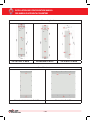
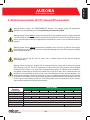
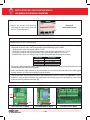
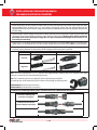
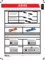
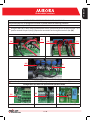
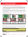
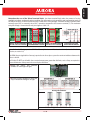
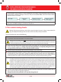
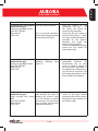
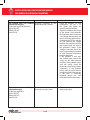
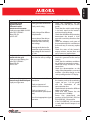
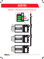
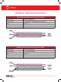
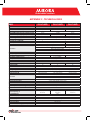
Photovoltaic Inverters Keep this document in a safe place IMPORTANT SAFETY INSTRUCTIONS! This manual contains important safety instructions that must be followed during the installation and start-up of the device. It’s recommended to give special attention to the paragraphs highlighted by the symbol , in order to reduce the risks of electric shock and prevent damage to the device. NOTE: This document contains proprietary information of Power-One, Inc. the contents of this document or any part thereof should not be reproduced or disclosed to any third party without Power-One’s express written consent. EN - English Photovoltaic Inverters Installation and Configuration Manual for Aurora Photovoltaic Inverters √ This document describes the installation and configuration procedure for Power-One Aurora Photovoltaic Inverters. The models this document refers to are shown in the table below. SINGLE PHASE PVI-3.0-TL-OUTD PVI-3.0-TL-OUTD-S THREE PHASE PVI-10.0-TL-OUTD PVI-10.0-TL-OUTD-S PVI-10.0-TL-OUTD-FS PVI-3.6-TL-OUTD PVI-3.6-TL-OUTD-S PVI-12.5-TL-OUTD PVI-12.5-TL-OUTD-S PVI-12.5-TL-OUTD-FS PVI-4.2-TL-OUTD PVI-4.2-TL-OUTD-S PVI-5000-TL-OUTD PVI-5000-TL-OUTD-S PVI-6000-TL-OUTD PVI-6000-TL-OUTD-S 1 - EN installation and configuRation manual foR auRoRa photoVoltaic inVeRteRs contents Useful information and safety regulations Package contents inspection Selection of installation location Wall mounting Electrical connections (AC, DC side and PE connection) 5.1 AC Side Connections 5.2 DC Side Connections 6 Configuration of input channel operating mode 7 RS485 communication line connection 8 Pre-commissioning checks 8.1 Electrical checks 8.2 Mechanical checks 9 Start up and connection to the grid 10 Possible configurations required at start up 10.1 Selection of grid standard 10.2 Other configurations 11 Start-Up Troubleshooting 12 Troubleshooting help 1 2 3 4 5 System structure 3 4 5 5 7 8 10 12 14 16 16 17 18 19 19 21 22 26 27 appendices: A – Pin-Out of RJ12 / RJ45 Connector B – Cable Wiring Diagram for RS485 Line C – Technical Data PVI-3.0/3.6/4.2-TL-OUTD PVI-5000/6000-TL-OUTD PVI-10.0/12.5-TL-OUTD 2 -en 1. Useful information and safety regulations This manual contains important safety instructions which must be carefully followed during the installation and commissioning of the device. It is advisable to pay particular attention to the paragraphs marked with the symbol , this will reduce the risk of electric shock and prevent damage to the device. All the operations described below must be carried out exclusively by qualified staff in compliance with national and local safety regulations. For all stages of installation, the instructions and warnings shown in the various chapters must be followed step by step so as to avoid danger situations or the possibility of damaging the equipment. Every operation that does not comply with these instructions will lead to the immediate loss of the warranty. There can be live parts, uninsulated parts and hot surfaces while the inverter is working. Unauthorized removal of the required protections, improper use, faulty installation or inappropriate operation and tampering with the unit (e.g. adding extra holes) give rise to the risk of serious damage to persons and things and lead to the immediate loss of the warranty. The system must be connected to the mains distribution system only after the Body appointed to distribute electricity has given its approval, as required by the national regulations in force. Check the national regulations and local standards so that the electric installation diagram complies with them. Always respect the nominal voltage and current data when planning the system (see the technical data table in Appendix C). 3 - EN EN - English Photovoltaic Inverters installation and configuRation manual foR auRoRa photoVoltaic inVeRteRs 2. package contents inspection Check that the package contents comply with the following list: ▪� � ▪� ▪� ▪� ▪� pVi-xx-tl-outd-yy inverter [1 piece] (xx = 3.0/3.6/4.2/5000/6000/10.0/12.5; yy = s /fs) Wall mounting bracket [1 piece] installation manual [1 piece] cd with communication sW and documentation in electronic format [1 piece] Kit consisting of: pVi-3.0-tl-outd pVi-3.6-tl-outd pVi-4.2tl-outd pVi-6000-tl-outd pVi-10.0-tl-outd pVi-5000-tl-outd pVi-12.5-tl-outd Screw 6.3x70 2 2 3 5 Dowel SX10 2 2 3 5 WAGO flat head angled screwdriver / / 1 / M20 cable gland 1 1 1 1 M25 cable gland 1 1 / / M32 cable gland / / 1 / M40 cable gland / / / 1 M25 cable gland nut 1 1 / / M32 cable gland nut / / 1 / 1 M40 cable gland nut / / / Red AWG10 cable with insulated female fastons 1 1 1 / Black AWG10 cable with insulated female fastons 1 1 1 / Black AWG12 cable with insulated female fastons / / / 2 36A3M20 type gasket 1 1 1 1 TGM58 cylinder 1 1 1 1 T20 TORX wrench 1 1 1 1 M6x10 screw 1 1 1 / D.18 washer 3 3 4 5 Perforated screw for front panel lead sealing / / 2 / Signal terminal board counterparts 2 2 / * Positive-input connector counterparts 2 3 4 ** Negative-input connector counterparts 2 3 4 ** *3-way terminal board counterparts (ALARM): 2 pieces; 8-way terminal board counterparts (signals): 2 pieces. **Per the PVI-10.0/12.5-TL-OUTD-S models: 4 pieces; for the PVI-10.0/12.5-TL-OUTD and PVI-10.0/12.5-TL-OUTD-FS models: 6 pieces. 4 -en s. 3. Selection of installation location The installation location of the AURORA inverter must be chosen taking in account the followings: Choose a location sheltered from direct sunlight or other sources of heat. Choose a well ventilated place so as to allow good circulation of air around the unit; avoid places where air cannot circulate freely around the unit. Choose a place with sufficient space around the unit to permit easy installation and removal of the object from the mounting surfaces. If more than one unit is installed, avoid placing one unit above the other so as to prevent overheating of the unit installed above through the heat given off by the one below. Some examples of multi-inverter installations are shown in the picture below. Minimum clearances around the unit. 4. Wall mounting The AURORA inverter should be mounted vertically, with a maximum inclination from the vertical of 5°. Any larger inclination from the vertical could reduce the power conversion capability with a consequent reduction in energy harvesting. To correctly wall mount the inverter, follow the following procedure: Drill Ø 10 mm holes to a depth of 75 mm in line with the support bracket’s fixing holes (det. [A]) Secure the inverter’s support bracket using the SX10 dowels and 6.3x70 screws provided. The inverter’s spring hook (det. [B]) must be positioned at the top; the fixing PEM M6 (det. [C]) must be positioned at the bottom. Hook the inverter to the bracket spring (det. [B]) by the screw holes in the bracket on the back of the inverter (det. [D]). Secure the lower part of the inverter to the PEM M6 on the bracket (det. [C]) using the M6x10 screw, the D.18 washer and the slot in the inverter’s lower flange (det. [E]). Note: In the PVI-10.0/12.5-TL-OUTD models the support bracket only permits the upper part of the inverter to be secured through the procedure previously described; to secure the lower part of the inverter, in the absence of the PEM M6, you must make additional holes in line with the slot in the inverter’s lower flange (det. [E]), and then use the SX10 dowels and 6.3x70 screws to secure the part to the wall. 5 - EN EN - English Photovoltaic Inverters installation and configuRation manual foR auRoRa photoVoltaic inVeRteRs inverter wall mounting brackets. pVi-3.0/3.6/4.2-tl-outd pVi-5000/6000-tl-outd pVi-10.0/12.5-tl-outd Rear of the inverter. pVi-3.0/3.6/4.2/5000/6000-tl-outd pVi-10.0/12.5-tl-outd 6 -en 5. Electrical connections (AC, DC side and PE connection) Warning! Aurora inverters are TRANSFORMERLESS inverters. This topology means the photovoltaic generator must be kept floating to earth: no generator pole should be earthed. Warning! Aurora inverters must be connected to earth (PE) by the prepared clamp and using a cable with a section suitable for the maximum failure current that can be had on the system. Any failure of an inverter which is not connected to earth by the appropriate terminal block or screws is to be considered outside the warranty. Warning! Aurora inverters cannot be powered by unlimited sources of current, e.g. batteries. Powering the device with this type of energy source can cause irreparable damage to the unit, with consequent invalidity of the warranty conditions. Warning! For the AC and DC side use cables with a suitable section for the internal conductor (refer to Appendix C). Warning! Aurora inverters are supplied with an internal protection system able to detect any ground fault occurring on the DC side of the equipment or inside the inverter. This protection system, designed to disconnect the inverter in the event of an accidental indirect contact or a breach of the insulation, is not capable of protecting the inverter from a dead short of one of the poles of the solar array when the equipment is connected to the AC grid (such an event could damage the inverter and such damage is not covered by the warranty). Further, this protection system is not capable of protecting the AC line to which the inverter is connected, for which you are recommended to install an automatic circuit breaker which will cut out in the event of a leakage on that line. The following table shows the characteristics of such a device that would be required for the various inverter models. Characteristics INVERTER MODEL Automatic PVI-3.0-TL-OUTD PVI-3.6-TL-OUTD PVI-4.2-TL-OUTD PVI-5000-TL-OUTD PVI-6000-TL-OUTD PVI-10.0-TL-OUTD PVI-12.5-TL-OUTD Circuit Breaker Type AUTOMATIC CIRCUIT BREAKER WITH MAGNOTHERMIC-DIFFERENTIAL PROTECTION Rated Voltage 230Vac 400Vac Rated Current 20 20 25 32 40 20 25 Magnetic Protection Characteristics B/C Differential Protection Type A/AC Differential Sensitivity 300mA Number of Poles 2 3/4 7 - EN EN - English Photovoltaic Inverters installation and configuRation manual foR auRoRa photoVoltaic inVeRteRs Remove the inverter’s front panel by unscrewing the screws on the panel with the Torx T20 wrench provided front panel: panel removal screws. 5.1 ac side connections Make sure the AC line is disconnected. Place the M25/M32/M40 cable gland in the hole used for the AC cables and pass the cable through for connection to the AC mains and PE connection. Use the following types of cable: •Single-phaseinverter:three-polecable(L+N+PE) •Three-phaseinverterwithtriangularconnectiontothegrid:four-polecable(R+S+T+PE) •Three-phaseinverterwithstarconnectiontothegrid:five-polecable(R+S+T+N+PE) The table below shows the locking ranges for the cable glands provided with the inverters. Cable Gland M20 M25 M32 M40 Locking Range 7 – 13 mm 10 – 17 mm 13 – 21 mm 19 – 28 mm If the green-yellow protection cable is separate to the mains connection cable, use one of the holes present and the related M20 cable gland supplied. √ Make sure that the cable selected for the connection has an external diameter that fits the cable gland through which it must be inserted to the inside the inverter. Connect the cables respecting the position of the earth lead (PE). In the PVI-3.0/3.6/4.2/5000/6000-TL-OUTD models it is also possible to connect the earth lead to the fastening screw on the board by means of an eyelet or spade lug cable terminal (det. [f]). ac teRminal BlocK [g] [f] [f] pVi-3.0/3.6/4.2-tl-outd pVi-5000/6000-tl-outd 8 -en pVi-10.0/12.5-tl-outd en - english photovoltaic inverters note: The specifications (maximum section and length of conductor) for a single AC cable are given in the figure at left. note: In the PVI-5000/6000 models, a WAGO screwdriver allowing the terminal block’s contacts to be opened is provided in the special kit. The procedure for opening the contacts and tightening cables is as follows: 1) Insert the screwdriver in slot with the screwdriver facing downwards. 2) Lightly press the screwdriver from the top to the bottom. 3) Insert the screwdriver until the clamp opens. 4) Insert the cable in the clamp. 5) Remove the screwdriver. note: In models PVI-3.0/3.6/4.2/10.0/12.5-TL-OUTD there is a metal turret (det. [G]) which, by means of the special bracket and perforated screw (det. [H]), allows the contacts to be closed with the related lead sealing. [h] note: In the PVI-10.0/12.5-TL-OUTD models, connection of neutral conductor (N) is optional and depends on the system in which the inverter is installed. If the AC Grid to which the inverter is connected includes single-phase devices or inverters which could create an imbalance in the three-phase system, you are recommended to use a star configuration (three-phase +N). However, where the circuit only includes 3ph inverters you are recommended to use a delta configuration (neutral not connected). In this case, the “3ph MOD” switch must be set to the Δ symbol (det. [I]) [i] Tighten the cable gland making sure that it grips the surface of the cable so that the seal is ensured and hence the level of environmental protection. It is possible to use one of the holes on the inverter for the passage of the green-yellow cable: in this case remove the screw cap and use the M20 cable gland for the cable’s passage. 9 - en installation and configuRation manual foR auRoRa photoVoltaic inVeRteRs 5.2 dc side connections Check the polarity of each couple of cables that must be connected to the inverter input: mark the cable corresponding to the positive pole so as to be able to distinguish it from the one corresponding to the negative pole. In the case of several strings, observe the correspondence between the negative and positive of each string. Check the open circuit voltage of each pair of cables which must be connected in input to the inverter: the value must in no case exceed the maximum input voltage of the inverter. Voltage values which exceed the permitted levels may irreparably damage the unit. any consequential damage to the inverter is not covered by the warranty. In the case of –FS models the input current in each connector must not exceed 12a (internal fuse current limit). Higher values can damage the fuse. For all the other models the input current limit is 20a for each connector. Crimp the MC4/WM counterparts to the string cables or the cables from the string disconnecting switches (external) paying attention to the polarity of the voltage and the connector / terminal. POLARITY CONNECTOR TERMINAL positive negative note: The French standard UTE-15-712-1 requires that supplementary retaining clips are assembled to the input connectors to avoid the risk of accidental disconnection. note: These retaining clips are not supplied in the accompanying assembly kit. The retaining clips can be ordered directly from Power-One, quoting the following codes: 3G830020000 (for Multicontat connectors) 3G830010000 (for Weidermüller connectors) procedure for assembling retaining clips and mc4 connectors (multicontat connectors) Insert the retaining clip as shown in the figure. fit the male connector into the female connector. 10 -en Procedure for assembling retaining clips and WM connectors (Weidermüller connectors) Insert the retaining clip as shown in the figure. Fit the male connector into the female connector. Note: After assembly, the retaining clip cannot be removed. Note: Once the male connector has been fitted to the female connector equipped with the clip, they can only be disconnected using the specific tool illustrated in the figure below. Multicontat Weidermüller Note: The disconnection tool for MC/WM connectors can be obtained from any Power-One products distributor. Ensure that the integrated switch (versions –S and –FS) is in the OFF position or that the external switches are open. Connect the connectors that you previously crimped to the input connectors in the lower part of the inverter, paying attention to the polarity. Lower part of PVI-3.0/3.6-TL-OUTD(-S) Lower part of PVI-4.2-TL-OUTD(-S) Lower part of PVI-5000/6000-TL-OUTD Lower part of PVI-10.0/12.5-TL-OUTD(-FS) 11 - EN EN - English Photovoltaic Inverters installation and configuRation manual foR auRoRa photoVoltaic inVeRteRs 6. configuration of input channel operating mode The two input channels can be configured in two modes: independent mode and parallel mode. The choice of input channel configuration depends on the photovoltaic generator’s characteristics and the inverter’s power and current limits. Refer to the system design documentation, or the documentation on the CD, for the inverter input configuration choice. Warning! For the two channels to be used in independent mode, it is a NECESSARY condition that the photovoltaic generator connected to each input has a maximum current and power below the channel’s current and power limit. Warning! For the two channels to be used in parallel mode, it is RECOMMENDED that the photovoltaic generator connected to the two inputs has strings with the same number of modules in series and that all the modules have the same installation conditions (inclination / orientation). √ Refer to the technical data table in Appendix C to find out the current and power limits of each input channel for the various inverter models. If the string’s current or power is above the current or power limit of the input channel to which it is connected, the two input channels must be configured in parallel. This condition also concerns the case where the photovoltaic generator comprises only one string with power above the inverter’s single input channel power limit. note: the inverters are pre-set in the factory with INDEPENDENT input channels. If the conditions shown above are not met, consult the photovoltaic system’s designer immediately. 12 -en EN - English Photovoltaic Inverters CONFIGURATION MODES FOR THE CHANNELS IN PARALLEL Should it be necessary to configure the channels in parallel, follow the following procedure: Remove the front panel of the inverter Using the AWG10/12 cables with insulated female fastons, connect the positive terminal of input 1 to a positive terminal of input 2 (det. [L]). Repeat the connection for the negative terminals (det. [M]). Parallel connection of the input channels [L] [M] [M] PVI-3.0/3.6/4.2-TL-OUTD [L] PVI-5000/6000-TL-OUTD [M] [L] PVI-10.0/12.5-TL-OUTD Act on the dip-switch identified by the INPUT MODE printing and put in on the PAR position (det. [N]). Configuration dip-switch for input channel operation mode. [N] PVI-3.0/3.6/4.2-TL-OUTD [N] [N] PVI-5000/6000-TL-OUTD 13 - EN PVI-10.0/12.5-TL-OUTD installation and configuRation manual foR auRoRa photoVoltaic inVeRteRs 7. configuration dip-switch for input channel operation mode. The RS485 communication port is the inverter’s communication port. AURORA uses a HALF-DUPLEX RS485 communication line madeupoftwotransmissionreceptionlines(+T/Rand–T/R)andareferencecommunicationline(RTN):allthreelinesmustbe wired in a daisy-chain (“in-out”). It is advisable to use a twisted-pair screened cable for the communication line: the screen must be earthed at only one point (typically near the monitoring system) and continuity inside each element of the chain must be given to the screen. Refer to Appendix B. The chain connection can be made without distinction by using the connector couples (one for in and one for out – det. [p]) or the terminal block (det. [Q] or det. [R]). The connectors are identified by the printing “RS485(A)” and “RS485(B)”: use of connector “A” as in and “B” as out is not compulsory (both connectors can be used as in or out). Refer to APPENDIX A for the PIN-OUT of the RJ12 and RJ45 connectors. The last inverter in the daisy chain must be “terminated” or the 120 Ohm communication line termination resistance must be activated by switching the dip-switch (det. [s]). [R] [p] [s] RJ12 connectors, terminal block and termination resistance for the pVi-3.0/3.6/4.2-tl-outd [Q] [R] [s] [p] RJ45 connectors, terminal block and termination resistance for the pVi-5000/6000-tl-outd [p] [s] RJ45 connectors, terminal block and termination resistance for the pVi-10.0/12.5-tl-outd The PVI-3.0/3.6/4.2/10.0/12.5-TL-OUTD models are equipped with a two-level terminal block allowing one level to be used for line-in connection and the other for line-out connection. The terminal block is also equipped with the LNK terminal for the PVI-3.0/3.6/4.2-TL-OUTD models and SCLD for the PVI-10.0/12.5-TL-OUTD models allowing continuity to be given to the cable screen. On the other hand the PVI-5000/6000-TL-OUTD models are equipped with a one-way terminal block (det. [Q]) and therefore it is necessary to couple the line-in and line-out leads in the same clamp. note about the built-in usB port in the pVi-3.0/3.6/4.2/5000/6000-tl-outd models The USB communication port is a service port. This port exists for diagnostic use and the internal controller’s firmware upgrade and is limited to service staff. Although drivers have been released (compatible with Windows XP and for which no upgrades are envisaged) which permit this port to be also used for monitoring (not recommended), the primary use remains strictly tied to debugging and updating the system. Power-One recommends the use of the RS485 port for the continuous monitoring of system data. With regard to the communication interface, the use of the dedicated Power-One PVI-RS485_RS232 or PVI-USB-RS485_232 type converter is strongly recommended in order to prevent compatibility problems that can sometimes be encountered with the standard models on the market. 14 -en en - english photovoltaic inverters note about the use of the “alarm” terminal block: the alarm terminal block makes the contacts of a relay available to indicate configurable alarm conditions (for information on the possibility and configuration modes of the “Alarm” function, see the user manual on the CD that comes in the package). The alarm contact is available under normally open (N.O.) or normally closed (N.C.) operation compared to the common terminal (C). The maximum rating for voltage / current that the relay can support is 230V / 1A. “alarm” terminal block in “alarm” terminal block in “alarm” terminal block in pVi-3.0/3.6/4.2-tl-outd pVi-5000/6000-tl-outd pVi-10.0/12.5-tl-outd functional diagram for the alarm contact Note: Perform the following operations ONLY if the "Germany" has been or will be selected as Nation (for details of the Nation selection, see section 10.1). The VDEW directive (applicable in Germany) requires that in a three-phase system the maximum imbalance between the phases is 4600 W. For PVI-6000-TL-OUTD models which have a nominal output power greater than this limit, a series of steps are required to ensure the limitation of the power in the event of phase imbalance. Bridge the “Alarm” and “Remote” contacts as in the figure at right. Wire the inverters together in one of the ways indicated in the figures at right. Wiring via terminals Wiring via RJ45 connectors 15 - en installation and configuRation manual foR auRoRa photoVoltaic inVeRteRs On the display, set the mode to “3 Phase Unbalanced” (see section 10 for information about using the display buttons). Select the “Settings” menu, key in the password (default 0000), select the “Remote Control” menu and select “3-PH Unbal.” In the event that a unit is switched off or becomes faulty, the other units are consequently set to limit their output power to 4600W avoiding any unbalance of the phases. 8. pre-commissioning checks Warning! Carrying out preliminary checks before commissioning the inverter is always recommended; this way you avoid possible damage to the unit that could be caused by its faulty installation. The main checks to carry out are the following: 8.1 electRical checKs PE connection check: check the inverter has an earth connection. Warning! Power One Aurora inverters must be connected to earth by the prepared clamp and using a cable with a section suitable for the maximum failure current that can be had on the system. Any failure of an inverter which is not connected to earth by the appropriate terminal block or fastening screws is to be considered outside the warranty. Check of the input voltage values: check that the inverter’s input voltage does not exceed the permitted limits (ref. technical data table in Appendix C). Voltage values above the specifications can irreparably damage the unit. any consequent failure of the inverter is to be considered outside the warranty. Check of the input voltage polarity: make sure the input voltage has the correct polarity. Check of the photovoltaic generator’s insulation to earth: use an insulation tester to make sure that insulation resistance to earth for the DC section of the system is greater than 1MOhm. Resistance insulation values of less than 1MOhm do not permit the inverter to complete the parallel with the grid. Resistance insulation values of less than 10MOhm can hide insulation problems that could be accentuated in periods when there is humidity in the photovoltaic generator. Warning! Aurora inverters are supplied with an internal protection system capable of detecting any earth leakage occurring on the DC side of the equipment or inside the inverter on the output side of the AC terminal connector. This protection system, designed to disconnect the inverter in the event of an accidental indirect contact or a breach of the insulation, is not capable of protecting the inverter from a dead short of one of the poles of the solar array when the equipment is connected to the AC grid (such an event could damage the inverter and such damage is not covered by the warranty). Further, this protection system is not capable of protecting the AC line to which the inverter is connected, for which you are recommended to install an automatic circuit breaker which will cut out in the event of a leakage on that line (see the table on page 7 for the characteristics of the automatic circuit breaker for each inverter model). Check of the grid voltage: check that the voltage of the grid to which the inverter will be connected complies with the values shown in the technical data table in Appendix C. Voltage values above the specifications can irreparably damage the unit. 16 -en EN - English Photovoltaic Inverters 8.2 MECHANICAL CHECKS Make sure the cable glands are mounted properly. The cable glands must be adequately locked and prevent any movement of the cable. Also make sure the cable glands are solidly fixed to the inverter’s chassis. Make sure that the gasket on the front panel has been correctly mounted. The gasket must completely cover the red line on the front of the inverter. Correct Mounting Reference Line Incorrect Mounting Fasten the inverter’s front panel by screwing the screws on the panel with the Torx T20 wrench provided. Warning! To ensure the inverter is waterproof, the front panel screws must be tightened to a torque wrench setting of at least 1.5 Nm (13.2 in-lbs). 17 - EN installation and configuRation manual foR auRoRa photoVoltaic inVeRteRs 9. start up and connection to the grid Once the pre-commissioning checks have been performed, it is possible to proceed to starting up the inverter and connecting it to the grid, following the procedure shown below. Switch the integrated switch (versions –S and –FS) to the ON position or close the external switches: If the input voltage applied to one of the two input channels is greater than the minimum starting voltage, the inverter will start up. When the inverter starts up for the first time it asks you to select the “Nation” of the country where it has been installed. See section 10.1 for more details about selecting the “Nation”. After you have set the Nation value, the message "Inizializing... Please Wait" is displayed. Depending on the input voltage value, the inverter will show various messages on the display and change the behaviour of the three LED: input voltage display message Vin<Vstart Waiting sun Vin>Vstart No Vac led status Green=FLASHING Yellow=OFF Red=OFF Green=FLASHING Yellow=ON Red=OFF description The input voltage is not sufficient to permit connection to the grid. There is sufficient input voltage to permit connection to the grid: the inverter waits until there is grid voltage to carry out the parallel. note: the inverter is powered ONLY by the voltage coming from the photovoltaic generator: presence of grid voltage alone IS NOT SUFFICIENT to permit the inverter to start up. note: the inverter start-up voltage (Vstart) is the input voltage value though which the inverter connects to the grid. This value avoids repeated connection and disconnection in periods of reduced radiation (typically in the morning). It is possible to modify the start-up voltage within a set range via the display and the four keys (Ref. Par. 10 and the technical data table in Appendix C). You are recommended to reduce the start-up voltage only when absolutely necessary, i.e. when the Configurator software indicates that the parameter needs to be changed to avoid repeated connection and disconnection to the AC Grid which could impact the reliability of the AC grid relays. note: the start-up voltage also sets the minimum voltage for the inverter to operate in MPPT. The inverter turns itself off because of input undervoltage when the input voltage (for each channel) drops below 70% of the start-up voltage (for the channel). With the inverter in “No Vac” status, close the AC switch downstream the inverter so as to apply the grid voltage to the inverter: the inverter performs the grid voltage check, measures the photovoltaic field’s insulation resistance against earth and carries out other self-diagnosis checks. During the checks before the parallel with the grid, the green LED keeps flashing, the others are off. note: during the grid voltage check and measurement of the insulation resistance, the values for the grid voltage and frequency and the insulation resistance measured by the inverter are shown on the display. The inverter completes parallel with the grid SOLELY if the grid parameters meet the ranges provided for by the regulations in force and if the insulation resistance is greater than 1Mohm. 18 -en If the preliminary checks for parallel to the grid are successful, the inverter connects to the grid and begins to export power to the grid. At this stage, the display shows the inverter’s parameters in cycles. The green LED stays lit whereas the others are off. Turning off the unit: follow the operations described for commissioning in reverse order. Opening the switch downstream the inverter will light up the yellow LED and display message W003 and then “No Vac”; opening the built-in disconnection switch or the external disconnection switches will completely turn off the unit (LED off and display off). Note: during the night, or more generally when the input voltage (DC) is insufficient to turn on the internal auxiliary power supply, the inverter will be completely off. 10. Possible configurations required at start up Below is a list of possible configurations that may be required at the inverter’s start-up. Other configurations are possible, these are not strictly related to the inverter’s start-up and for them you should refer to the User Manual. The following configurations can be modified with the four keys on the display (Esc, Up, Down and Enter); by pressing the Up and Down keys you go from one item to another or scroll the numerical scale, by pressing the Esc key you return to the previous menu and by pressing the Enter key you go to the sub-menu corresponding to the selected item or you go to the next figure to modify. To access the following functions, you have to open the “Settings” item from the main menu, entering the password which is 0000 by default. 10.1 SELECTION OF GRID STANDARD When the inverter starts up for the first time it asks you to select the “Nation” of the country where it has been installed. Use the keys on the display to scroll and select one of the Nations listed in the following table: NATION (displayed) No Nation Australia BENELUX China Czech Rep. France Germany Greece Ireland Italy Portugal Spain UK LANGUAGE English English French English Czech French German English English Italian English Spanish English 19 - EN EN - English Photovoltaic Inverters installation and configuRation manual foR auRoRa photoVoltaic inVeRteRs Warning! Select the grid standard carefully to avoid any problems with the grid connection. The selection of the grid standard automatically configures the inverter to ensure that it complies with local standards. After you have selected the required Nation, press ENTER: you will be requested to confirm your choice by holding down the ENTER key for 5 seconds. Warning! From the moment that the grid standard is set you have 24 hours to make any changes to the value, after which the “Nation Select” functionality is blocked, and any subsequent changes can only be made using a password provided on request by Power-One. note: In the event that an error is made in the selection of the Nation value, it is possible, during the first 24 hours when the inverter is powered*, to modify the Nation value by selecting: settings -> nation -> nation select. You can check how much time remains before the “Nation Select” button is blocked, by selecting settings -> nation -> Remaining time. After 24 hours* the inverter is powered, you can only change the Nation setting using a password provided on request by Power-One. To request this password, contact the Service Power-One and communicate the serial number (S/N) of the inverter and its “Authorization Key” code, which can be obtained by selecting settings -> nation -> nation select. After obtaining the password, select settings -> nation -> nation select , press ENTER and enter the password supplied by Power-One. After you have entered the password, the “Nation” value can be changed for a further period of 24 hours. * The 24 hour period begins (and continues) when you select a Nation 20 -en 10.2 OTHER CONFIGURATIONS Configuration of the RS458 port address (Address): When there are several inverters wired on the same RS485 line (ref. Par. 7), the RS485 port address must be different for each inverter (N.B. “Auto” is not permitted as an address); to modify the address you have to access the Address sub-menu. Date/Time Settings (Time): On first start-up of the inverter, it is necessary to configure the date and time by accessing the Time sub-menu. Language setting (Language): If required, you can change the default language, set automatically when “Nation” was selected, to one of the following: ENGLISH, GERMAN, FRENCH, ITALIAN, SPANISH or CZECH. To change the language, select the Language submenu. Start-up voltage (Vstart): The start-up voltage can be regulated by accessing the Vstart sub-menu and, in the case of independent channel configuration, it is possible to configure the Vstart for channel 1 and channel 2 separately. MPPT scanning (MPPTScan EN/DIS): The inverter uses the MPPT Scan to search periodically for an absolute power peak from the relative peaks that are formed when part of the solar array is shaded. Scan interval (Scan Interval): The Scan Interval function determines the time interval between consecutive MTTP scans. 21 - EN EN - English Photovoltaic Inverters installation and configuRation manual foR auRoRa photoVoltaic inVeRteRs 11. start-up troubleshooting Start-up Troubleshooting concerns the solving of the main problems that can occur during the first start-up phase. Should problems arise in the unit’s commissioning phase, it is possible to solve the problem by looking for the corresponding problem in the table and following the instructions. Warning! Tampering with the unit, even to solve a problem, leads to the loss of the unit’s warranty. Before undertaking any tampering that could cause the loss of warranty, contact the Power-One customer assistance service. problem the inverter does not start. Display message: none Green LED: OFF Yellow LED: OFF Red LED: OFF possible causes There is no input voltage (DC) • present or it is present but with reversed polarity. • • • the inverter does not establish parallel with the grid. Display message: No Vac Green LED: FLASHING Yellow LED: ON Red LED: OFF There is no grid voltage the inverter does not establish parallel with the grid. Display message: PARAMETERS OUTSIDE TOLERANCE. Green LED: FLASHING Yellow LED: ON Red LED: OFF Faulty grid cable connection. • • • 22 -en checks/possible solutions Check the status of the builtin disconnecting switch or the external disconnecting switches; Check the state of any internal or external fuses; Check the inverter’s input voltage polarity; Check that the input voltage is at least more than 120V (refer to the technical data). Check the status of the AC side disconnecting switch; Check the inverter’s AC side connections (ref. par. 5 of this guide) and repeat the commissioning procedure. Check the inverter’s AC side connections (ref. par. 5 of this guide) and repeat the commissioning procedure. EN - English Photovoltaic Inverters Problem Possible causes • The inverter does not establish Faulty grid cable connection. parallel with the grid Display message: W003 Grid Fail Green LED: FLASHING One or more grid parameters • Yellow LED: ON are outside the range permitted Red LED: OFF for connection to the grid. • Checks/Possible solutions Check the inverter’s AC side connections (ref. par. 5 of this guide) and repeat the commissioning procedure. Check that the grid voltage, at terminal block heads, is within the range (width and frequency) permitted for the inverter’s operation and repeat the commissioning procedure. If this error is frequently repeated, consult the user manual for further information. The inverter does not establish The grid voltage exceeds the • maximum operating value parallel with the grid. (264V L-N) Display message: W003 Grid Fail Green LED: FLASHING Yellow LED: ON Red LED: OFF Reduce the power of the photovoltaic generator (by disconnecting one or more strings or creating shading on the photovoltaic generator). If the phenomenon disappears, but you still note an increase in the grid voltage, the problem is to be found in high line impedance. The inverter does not establish parallel with the grid. Display message: E013 Wrong Mode. Green LED: FLASHING Yellow LED: ON Red LED: OFF Check the status of selection switch for the input channel operating mode and for jumpers between the input channels (ref. par. 6 of this guide). Faulty configuration of the • input channels: the switch for selecting the channel mode is set on channels in parallel, but the inputs on the inverter have not been short-circuited (independent channels). 23 - EN installation and configuRation manual foR auRoRa photoVoltaic inVeRteRs problem possible causes the inverter does not establish Insulation resistance to the • photovoltaic field <1Mohm. parallel with the grid. Display message: E 025 Riso Low. Green LED: OFF • Yellow LED: OFF Red LED: ON • • • the inverter does not establish pa- The inverter detects excessive dispersion current to earth. rallel with the grid. Display message: E018. Green LED: OFF Yellow LED: OFF Red LED: ON 24 -en • checks/possible solutions Check the inverter’s DC side connections (ref. par. 5 of this guide) and repeat the commissioning procedure. Check the adequacy and status of the devices used externally for protection against transitory over voltage. Remove them and retry. If necessary, replace them. Disconnect the DC line and the AC line. Measure the voltage between the positive pole (and the negative pole) for each of the generator’s strings. If the voltage is near zero, one of the poles is (accidentally) connected to earth. Check the connections between the panels. If the problem is with only one inverter input, reverse the strings for the input channels and retry. If the problem moves with the strings, check for dispersions in the string (cables, connectors). If the problem moves with the input channel, it could be a fault in the inverter. If this error is frequently repeated, consult the user manual for further information. Carry out the same checks as in the previous point. EN - English Photovoltaic Inverters Problem Intervention of the magneto-thermal differential switch downstream the inverter. Display message: W003 Grid Fail Green LED: FLASHING Yellow LED: ON Red LED: OFF Possible causes Faulty grid cable connection. • Faulty switch sizing. • Faulty sizing of the differential protection. Intervention of the devices external to the inverter for protection from transitory overvoltage. • • Damage to the devices for protection against transitory • overvoltage on the inverter’s AC side. The inverter does not establish The inverter’s input voltage is • less than the start-up voltage. parallel with the grid Display message: Waiting Sun • Green LED: FLASHING Yellow LED: ON • Red LED: OFF • The inverter does not commu- Faulty communication line nicate through the RS485 port. connection. Display message: none. Faulty assignment of addresses to the inverters. • • Faulty assignment of communication speed (baud- • rate). • Use of an inappropriate signal converter. • 25 - EN Checks/Possible solutions Check the connections on the inverter’s AC side (ref. par. 5 of this guide). Check that the switch’s rated voltage is (at least) equal to the inverter’s maximum output voltage. Check that the differential protection downstream the inverter is A/AC type with a sensitivity of not less than 300mA. Check the adequacy and status of the protection devices used. Remove them and retry. If necessary, replace them. Check the status of the inverter’s output varistors; remove them and retry. If necessary, replace them. Check that the voltage at the input terminals is greater than the start-up voltage. Check that the radiation conditions are sufficient to operate the system. Check the strings’ and the DC side’s connections. Check the documentation on the sizing of the photovoltaic system and evaluate a possible change to the start-up voltage on the LCD display. Check the connections between the inverters and to the monitoring system (ref. par. 7 of this guide) and the termination of the communication line. Check that each inverter has different address to the others. Check that each inverter has the baud-rate set at 19200bps. Power One recommends the purchase of the PVI-RS485_RS232 or PVI-USB-RS485_232 converter. If the PVI-USB-RS485_232 converter is used, check that the output is set correctly. installation and configuRation manual foR auRoRa photoVoltaic inVeRteRs 12. troubleshooting help If it has not been possible to solve the problem through the start-up troubleshooting (ref. Par. 10) and the complete troubleshooting in the user manual, the following procedure should be followed: Check that connections between the Aurora, the photovoltaic generator and the grid have been correctly carried out. Carefully observe which of the LED is flashing or is stably lit and the notice text appearing on the display, with particular reference to the error code. If you have not been able to remove the malfunction, contact customer service or the installer to request assistance. Before contacting customer service make sure the following information is available in order to maximize the effectiveness of the intervention: information on the inverter: •Aurorainvertermodel. •Serialnumber •Weekofproduction •Inputchannelconfiguration(parallel/independent) information on the photovoltaic generator: •Brandandmodelofphotovoltaicpanels •Numberofstrings •Numberofpanelsperstring note: it is advisable to use the special “SYSTEM STRUCTURE” form on the next page to collect this information so the information is always available in case of need. Brief description of the fault? Can the fault be reproduced? If so, how? Does the fault repeat itself in cycles? If so, how often? Was the fault apparent at the moment of installation? If so, has it got worse? What are the atmospheric conditions when the fault occurs? 26 -en SYSTEM STRUCTURE You are recommended to fill in this page with the information relating to the system and possibly supplement it with a copy of the system’s wiring diagram. The information on this page could be very handy, should it be necessary to contact the Power One help service. AURORA INVERTER Model (*): Serial Number (*): Week of production (*): PARALLEL INPUT CHANNEL CONFIGURATION PV GENERATOR Module brand: ............................................................. Module model: ............................................................ Number of modules in series/string: ................... Number of strings in parallel: ................................ INDEPENDENT INPUT CHANNEL CONFIGURATION MPPT1 PV GENERATOR Module brand: .................................................................... Module model: ................................................................... Number of modules in series/string: .......................... Number of strings in parallel: ........................................ MPPT2 PV GENERATOR Module brand: .................................................................... Module model: ................................................................... Number of modules in series/string: .......................... Number of strings in parallel: ........................................ (*) Refer to the product’s identification label on the right side of the inverter. Date of installation: Date of commissioning: ......................................... ......................................... Stamp / Signature of installer (*): (*) This document has no contractual value between the owner of the system and the installer. 27 - EN EN - English Photovoltaic Inverters appendiX appendiX a – pin-out of RJ12 / RJ45 connectoRs RJ12 connectors description 1 signal name not used 2 +tR + data line Required for RS485 communication. 3 +R Remote off Required or Remote OFF control 4 -tR - data line Required for RS485 communication. 5 not used 6 Rtn pin # signal Return Common reference for logical signals. RJ45 connectors pin # signal name 1 not used 2 not used 3 +tR + data line Required for RS485 communication. 4 +R Remote off Required or Remote OFF control. 5 -tR - data line Required for RS485 communication. 6 not used 7 Rtn 8 not used description signal Return Common reference for logical signals. Photovoltaic Inverters APPENDIX B – Cable wiring diagram for RS485 line appendiX appendiX B – Rs485 caBle specification single tWisted paiR Rs485 caBle specification Type of Cable RS485 EIA Application Cable Structure 1twistedpair+1singleconductor,shielded AWG 22 - 24 Charateristic Impedance 120 Ω Working Frequency 1 kHz / 1 MHz douBle tWisted paiR Rs485 caBle specification Type of Cable RS485 EIA Application Cable Structure 2 twisted pair, shielded AWG 22 - 24 Charateristic Impedance 120 Ω Working Frequency 1 kHz / 1 MHz Photovoltaic Inverters APPENDIX C - Technical data Model PVI-3.0-TL-OUTD PVI-3.6-TL-OUTD PVI-4.2-TL-OUTD INPUT PARAMETERS Nominal DC Power [kW] 3,12 3,75 4,375 Max. Recommended DC Power [kW] 3,5 4,15 4,82 Operating Input Voltage Range [V] 0,7xVstart - 580 (360 nominal) Full Power MPPT input voltage range (symmetrical load) [V] 160-530 120-530 140-530 Full Power MPPT input voltage range (asymmetrical load) [V] 200-530 (@ 2kW) / 112-530 (@ 1,12kW) 190-530 (@ 3kW) / 90-530 (@ 0,75kW) 190-530 (@ 3kW) / 90-530 (@ 1,38kW) Absolute Max. Input Voltage [V] 600 Activation voltage “Vstart” [V] 200 nominal (adjustable within the range 120Vdc-350Vdc, independently/each input) 2 No of independent MPPT trackers 2 3 Max. Input Power, each MPPT [kW] 2 ( 1 each MPPT ) 3 ( 2 for MPPT1, 1 for MPPT2 ) No. of DC Inputs 10 ( 12,5 short circuit ) 16 ( 20 short circuit ) Max. DC Current, each MPPT [A] 4 (2 positive, 2 negative) 6 (3 positive, 3 negative) Weidermüller / MultiContact Ø 4mm (male - positive input + female - negative input) DC Connection Mating cable connector included Conductor cross section: 4-6mmq/AWG12-10 - Cable Ø w/insulator: 3-6mm INPUT PROTECTION Reverse polarity protection Yes Fuse rating, each input (-FS suffix versions only) NA NA NA Thermally Protected DC side varistor 4 ( 2 for each MPPT ) PV array Insulation Control according to VDE0126-1-1 DC Switch (-S/-FS suffix versions only) Integrated (Rating : 600Vdc / 25A) OUTPUT PARAMETERS Nominal AC Power [up to 50°C, kW] 3 3,6 4,2 Max. AC Power [kW] 3,3 4 4,6 AC Grid Connection single phase ( Live, Neutral, PE ) Nominal AC Voltage [V] 230 AC Voltage Range [V] 180-264 (may vary to comply with regulations in each country) Nominal AC Frequency [Hz] 50 Max. AC Line Current [A] 14,5 ( 16 short circuit ) 17,2* ( 19 short circuit ) 20 ( 22 short circuit ) Screw terminal block AC Connection Conductor cross section: Solid 0,5-16mmq / Stranded: 0,5-10mmq / AWG20-6 Cable Gland: M25 - Cable Ø: 10-17mm Line Power Factor >0,995 AC Current Distortion [THD%] <3,5% at rated power with sine wave voltage OUTPUT PROTECTION 2 ( Live - Neutral / Live - PE ) AC side varistors Ground fault protection (AC + DC leakage current) according to VDE0126-1-1 ENVIRONMENTAL PARAMETERS Cooling Natural cooling -25 / +60 (output power derating -25 / +60 (output power derating -25 / +60 (output power derating Ambient Temp. Range [°C] above 50 °C) above 55 °C) above 50 °C) Opertaing Altitude [m] 2000 Acoustical Noise [dBA] < 50 @ 1mt Environmental IP Rating IP65 Relative Humidity 0-100% condensing MECHANICAL Dimensions [H x W x D] 547 x 325 x 210 Overall Dimensions (whit flanges) [H x W x D] 689 x 325 x 222 Weight [kg] (*) Limited to 16A for UK G83/1 Version. appendiX appendiX c - technical data model input paRameteRs nominal dc power [kW] max. Recommended dc power [kW] operating input Voltage Range [V] full power mppt input voltage range (symmetrical load) [V] full power mppt input voltage range (asymmetrical load) [V] absolute max. input Voltage [V] activation voltage “Vstart” [V] no of independent mppt trackers max. input power, each mppt [kW] no. of dc inputs max. dc current, each mppt [a] dc connection input pRotection Reverse polarity protection fuse rating, each input (-fs suffix versions only) dc side varistors pV array insulation control dc switch (-s/-fs suffix versions only) output paRameteRs nominal ac power [up to 50°c, kW] max. ac power [kW] ac grid connection nominal ac Voltage [V] ac Voltage Range [V] nominal ac frequency [hz] max. ac line current [a] ac connection line power factor ac current distortion [thd%] output pRotection ac side varistors ground fault protection (ac + dc leakage current) enViRonmental paRameteRs cooling ambient temp. Range [°c] opertaing altitude [m] acoustical noise [dBa] environmental ip Rating Relative humidity mechanical BoX dimensions [h x W x d] overall dimensions (whit flanges) [h x W x d] Weight [kg] (**) Limited to 4600W for Germany. pVi-5000-tl-outd pVi-6000-tl-outd 4,8 5,75 6,2 6,9 0,7xVstart - 580 (360 nominal) 150-530 180-530 220-530 (@ 4kW) / 90-530 (@ 0,8kW) 220-530 (@ 4kW) / 120-530 (@ 2,2kW) 600 200 nominal (adjustable within the range 120Vdc-350Vdc, independently/each input) 2 4 4 (2 each MPPT) 18 (22 shortcircuit) 8xWeidermüller/MultiContactØ4mm(4male-positiveinput+4female-negativeinput) Mating cable connector included Conductor cross section: 4-6mmq/AWG12-10 - Cable Ø w/insulator: 3-6mm Yes NA NA 4 ( 2 for each MPPT ), thermally protected according to VDE0126-1-1 Integrated (Rating: 600Vdc / 25Adc) 5(**) 5(**) 6 6 singlephase230Vac50Hz+PE 230 180-264 (may vary to comply with regulations in each country) 50 25 (32 short circuit) 30 (40 short circuit) Cage-clamp terminal block Conductor Cross Section: Solid: 0,5-16mmq / Stranded: 0,5-10mmq / AWG20-6 Cable Gland: M32 - Cable Ø: 13-21mm >0,995 <3,5% at rated power with sine wave voltage 2, plus gas arrester to ground according to VDE0126-1-1 Natural cooling -25/+60(outputpowerderatingabove60°C) -25/+60(outputpowerderatingabove50°C) 2000 <50 @1mt IP65 0-100% condensing 740 x 325 x 208 910 x 325 x 222 26 Photovoltaic Inverters APPENDIX C - Technical data Model INPUT PARAMETERS Nominal DC Power [kW] Max. Recommended DC Power [kW] Operating Input Voltage Range [V] Full Power MPPT input voltage range (symmetrical load) [V] Full Power MPPT input voltage range (asymmetrical load) [V] Absolute Max. Input Voltage [V] Activation voltage “Vstart” [V] No of independent MPPT trackers Max. Input Power, each MPPT [kW] No. of DC Inputs Max. DC Current, each MPPT [A] DC Connection INPUT PROTECTION Reverse polarity protection Fuse rating, each input (-FS suffix versions only) DC side varistors PV array Insulation Control DC Switch (-S/-FS suffix versions only) OUTPUT PARAMETERS Nominal AC Power [up to 50°C, kW] Max. AC Power [kW] AC Grid Connection Nominal AC Voltage [V] AC Voltage Range [V] Nominal AC Frequency [Hz] Max. AC Line Current [A] AC Connection Line Power Factor AC Current Distortion [THD%] OUTPUT PROTECTION AC side varistors Ground fault protection (AC + DC leakage current) ENVIRONMENTAL PARAMETERS Cooling Ambient Temp. Range [°C] Opertaing Altitude [m] Acoustical Noise [dBA] Environmental IP Rating Relative Humidity MECHANICAL BOX Dimensions [H x W x D] Overall Dimensions (whit flanges) [H x W x D] Weight [kg] (***) Limited to 10000W for Benelux. PVI-10.0-TL-OUTD PVI-12.5-TL-OUTD 10,3 11,4 12,8 14,3 0,7xVstart - 850 (580 nominal) 300-750 360-750 380-750 (@ 6,8kW) / 195-750 (@ 3,5kW) 445-750 (@ 8kW) / 270-750 (@ 4,8kW) 900 360 nominal (adjustable within the range 250Vdc-500Vdc, independently/each input) 2 6,8 8 6 (3 each MPPT, optionally fused) in PVI-10.0/12.5-TL-OUTD and in PVI-10.0/12.5-TL-OUTD-FS version 4 (2 each MPPT) in PVI-10.0/12.5-TL-OUTD-S version 18 (22 shortcircuit) 12 x Weidermüller / MultiContact Ø 4mm (6 male - positive input + 6 female - negative input) in PVI-10.0/12.5-TL-OUTD and in PVI-10.0/12.5-TL-OUTD-FS version 8 x Weidermüller / MultiContact Ø 4mm (4 male - positive input + 4 female - negative input) in PVI-10.0/12.5-TL-OUTD-S version Mating cable connector included Conductor cross section: 4-6mmq/AWG12-10 - Cable Ø w/insulator: 3-6mm Yes 10Adc / 900Vdc 4 ( 2 for each MPPT ), thermally protected according to VDE0126-1-1 Integrated (Rating: 1000Vdc / 25Adc) 10 12,5 11(***) 13,8 3 phase 400Vac 50Hz with or without neutral (3 or 4 wires) + PE 400V 320-480Vac (may vary to comply with regulations in each country) 50 16,6A per phase (19A short circuit) 20A per phase (22A short circuit) Screw terminal block Conductor Cross Section: Solid: 0,5-16mmq / Stranded: 0,5-10mmq / AWG20-6 Cable Gland: M40 - Cable Ø: 19-28mm >0,995 <2% at rated power with sine wave voltage 3, star connected to common point, plus gas arrester to ground according to VDE0126-1-1 Natural cooling -25 / +60 (output power derating above 55 °C) -25 / +60 (output power derating above 50 °C) 2000 <50 @1mt IP65 0-100% condensing 645 x 645 x 211 716 x 645 x 224 38 Photovoltaic Inverters


![Fronius Primo:, , [42,0426,0204,PB]](http://vs1.manualzilla.com/store/data/006066638_1-53eaca308649d96bdc628a0452b266c5-150x150.png)