1
INSTALLATION AND
OPERATION MANUAL
FCD-IP
E1/T1 or Fractional E1/T1 Access Unit with
Integrated Router
Version 4.2
The Access Company
FCD-IP
E1/T1 or Fractional E1/T1 Access Unit with Integrated
Router
Version 4.2
Installation and Operation Manual
Notice
This manual contains information that is proprietary to RAD Data Communications Ltd. ("RAD").
No part of this publication may be reproduced in any form whatsoever without prior written
approval by RAD Data Communications.
Right, title and interest, all information, copyrights, patents, know-how, trade secrets and other
intellectual property or other proprietary rights relating to this manual and to the FCD-IP and any
software components contained therein are proprietary products of RAD protected under
international copyright law and shall be and remain solely with RAD.
The FCD-IP product name is owned by RAD. No right, license, or interest to such trademark is
granted hereunder, and you agree that no such right, license, or interest shall be asserted by
you with respect to such trademark. The RAD name, logo, logotype, and the terms EtherAccess,
TDMoIP and TDMoIP Driven, and the product names Optimux and IPmux, are registered
trademarks of RAD Data Communications Ltd. All other trademarks are the property of their
respective holders.
You shall not copy, reverse compile or reverse assemble all or any portion of the Manual or the
FCD-IP. You are prohibited from, and shall not, directly or indirectly, develop, market, distribute,
license, or sell any product that supports substantially similar functionality as the FCD-IP, based
on or derived in any way from the FCD-IP. Your undertaking in this paragraph shall survive the
termination of this Agreement.
This Agreement is effective upon your opening of the FCD-IP package and shall continue until
terminated. RAD may terminate this Agreement upon the breach by you of any term hereof.
Upon such termination by RAD, you agree to return to RAD the FCD-IP and all copies and
portions thereof.
For further information contact RAD at the address below or contact your local distributor.
International Headquarters
RAD Data Communications Ltd.
North America Headquarters
RAD Data Communications Inc.
24 Raoul Wallenberg Street
Tel Aviv 69719, Israel
Tel: 972-3-6458181
Fax: 972-3-6498250, 6474436
E-mail: [email protected]
900 Corporate Drive
Mahwah, NJ 07430, USA
Tel: (201) 5291100, Toll free: 1-800-4447234
Fax: (201) 5295777
E-mail: [email protected]
© 1991–2008 RAD Data Communications Ltd.
Publication No. 676-200-05/07
Limited Warranty
RAD warrants to DISTRIBUTOR that the hardware in the FCD-IP to be delivered hereunder shall be
free of defects in material and workmanship under normal use and service for a period of twelve
(12) months following the date of shipment to DISTRIBUTOR.
If, during the warranty period, any component part of the equipment becomes defective by
reason of material or workmanship, and DISTRIBUTOR immediately notifies RAD of such defect,
RAD shall have the option to choose the appropriate corrective action: a) supply a replacement
part, or b) request return of equipment to its plant for repair, or c) perform necessary repair at
the equipment's location. In the event that RAD requests the return of equipment, each party
shall pay one-way shipping costs.
RAD shall be released from all obligations under its warranty in the event that the equipment has
been subjected to misuse, neglect, accident or improper installation, or if repairs or
modifications were made by persons other than RAD's own authorized service personnel, unless
such repairs by others were made with the written consent of RAD.
The above warranty is in lieu of all other warranties, expressed or implied. There are no
warranties which extend beyond the face hereof, including, but not limited to, warranties of
merchantability and fitness for a particular purpose, and in no event shall RAD be liable for
consequential damages.
RAD shall not be liable to any person for any special or indirect damages, including, but not
limited to, lost profits from any cause whatsoever arising from or in any way connected with the
manufacture, sale, handling, repair, maintenance or use of the FCD-IP, and in no event shall
RAD's liability exceed the purchase price of the FCD-IP.
DISTRIBUTOR shall be responsible to its customers for any and all warranties which it makes
relating to FCD-IP and for ensuring that replacements and other adjustments required in
connection with the said warranties are satisfactory.
Software components in the FCD-IP are provided "as is" and without warranty of any kind. RAD
disclaims all warranties including the implied warranties of merchantability and fitness for a
particular purpose. RAD shall not be liable for any loss of use, interruption of business or
indirect, special, incidental or consequential damages of any kind. In spite of the above RAD
shall do its best to provide error-free software products and shall offer free Software updates
during the warranty period under this Agreement.
RAD's cumulative liability to you or any other party for any loss or damages resulting from any
claims, demands, or actions arising out of or relating to this Agreement and the FCD-IP shall not
exceed the sum paid to RAD for the purchase of the FCD-IP. In no event shall RAD be liable for
any indirect, incidental, consequential, special, or exemplary damages or lost profits, even if RAD
has been advised of the possibility of such damages.
This Agreement shall be construed and governed in accordance with the laws of the State of
Israel.
Product Disposal
To facilitate the reuse, recycling and other forms of recovery of waste
equipment in protecting the environment, the owner of this RAD product is
required to refrain from disposing of this product as unsorted municipal
waste at the end of its life cycle. Upon termination of the unit’s use,
customers should provide for its collection for reuse, recycling or other form
of environmentally conscientious disposal.
General Safety Instructions
The following instructions serve as a general guide for the safe installation and operation of
telecommunications products. Additional instructions, if applicable, are included inside the
manual.
Safety Symbols
This symbol may appear on the equipment or in the text. It indicates potential
safety hazards regarding product operation or maintenance to operator or service
personnel.
Warning
Danger of electric shock! Avoid any contact with the marked surface while the
product is energized or connected to outdoor telecommunication lines.
Protective ground: the marked lug or terminal should be connected to the building
protective ground bus.
Warning
Some products may be equipped with a laser diode. In such cases, a label with the
laser class and other warnings as applicable will be attached near the optical
transmitter. The laser warning symbol may be also attached.
Please observe the following precautions:
•
Before turning on the equipment, make sure that the fiber optic cable is intact
and is connected to the transmitter.
•
Do not attempt to adjust the laser drive current.
•
Do not use broken or unterminated fiber-optic cables/connectors or look
straight at the laser beam.
•
The use of optical devices with the equipment will increase eye hazard.
•
Use of controls, adjustments or performing procedures other than those
specified herein, may result in hazardous radiation exposure.
ATTENTION: The laser beam may be invisible!
In some cases, the users may insert their own SFP laser transceivers into the product. Users are
alerted that RAD cannot be held responsible for any damage that may result if non-compliant
transceivers are used. In particular, users are warned to use only agency approved products that
comply with the local laser safety regulations for Class 1 laser products.
Always observe standard safety precautions during installation, operation and maintenance of
this product. Only qualified and authorized service personnel should carry out adjustment,
maintenance or repairs to this product. No installation, adjustment, maintenance or repairs
should be performed by either the operator or the user.
Handling Energized Products
General Safety Practices
Do not touch or tamper with the power supply when the power cord is connected. Line voltages
may be present inside certain products even when the power switch (if installed) is in the OFF
position or a fuse is blown. For DC-powered products, although the voltages levels are usually
not hazardous, energy hazards may still exist.
Before working on equipment connected to power lines or telecommunication lines, remove
jewelry or any other metallic object that may come into contact with energized parts.
Unless otherwise specified, all products are intended to be grounded during normal use.
Grounding is provided by connecting the mains plug to a wall socket with a protective ground
terminal. If a ground lug is provided on the product, it should be connected to the protective
ground at all times, by a wire with a diameter of 18 AWG or wider. Rack-mounted equipment
should be mounted only in grounded racks and cabinets.
Always make the ground connection first and disconnect it last. Do not connect
telecommunication cables to ungrounded equipment. Make sure that all other cables are
disconnected before disconnecting the ground.
Connecting AC Mains
Make sure that the electrical installation complies with local codes.
Always connect the AC plug to a wall socket with a protective ground.
The maximum permissible current capability of the branch distribution circuit that supplies power
to the product is 16A. The circuit breaker in the building installation should have high breaking
capacity and must operate at short-circuit current exceeding 35A.
Always connect the power cord first to the equipment and then to the wall socket. If a power
switch is provided in the equipment, set it to the OFF position. If the power cord cannot be
readily disconnected in case of emergency, make sure that a readily accessible circuit breaker or
emergency switch is installed in the building installation.
In cases when the power distribution system is IT type, the switch must disconnect both poles
simultaneously.
Connecting DC Power
Unless otherwise specified in the manual, the DC input to the equipment is floating in reference
to the ground. Any single pole can be externally grounded.
Due to the high current capability of DC power systems, care should be taken when connecting
the DC supply to avoid short-circuits and fire hazards.
DC units should be installed in a restricted access area, i.e. an area where access is authorized
only to qualified service and maintenance personnel.
Make sure that the DC power supply is electrically isolated from any AC source and that the
installation complies with the local codes.
The maximum permissible current capability of the branch distribution circuit that supplies power
to the product is 16A. The circuit breaker in the building installation should have high breaking
capacity and must operate at short-circuit current exceeding 35A.
Before connecting the DC supply wires, ensure that power is removed from the DC circuit. Locate
the circuit breaker of the panel board that services the equipment and switch it to the OFF
position. When connecting the DC supply wires, first connect the ground wire to the
corresponding terminal, then the positive pole and last the negative pole. Switch the circuit
breaker back to the ON position.
A readily accessible disconnect device that is suitably rated and approved should be incorporated
in the building installation.
If the DC power supply is floating, the switch must disconnect both poles simultaneously.
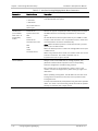
Connecting Data and Telecommunications Cables
Data and telecommunication interfaces are classified according to their safety status.
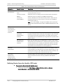
The following table lists the status of several standard interfaces. If the status of a given port
differs from the standard one, a notice will be given in the manual.
Ports
Safety Status
V.11, V.28, V.35, V.36, RS-530, X.21,
10 BaseT, 100 BaseT, Unbalanced E1,
E2, E3, STM, DS-2, DS-3, S-Interface
ISDN, Analog voice E&M
SELV
xDSL (without feeding voltage),
Balanced E1, T1, Sub E1/T1
TNV-1 Telecommunication Network Voltage-1:
Ports whose normal operating voltage is within the
limits of SELV, on which overvoltages from
telecommunications networks are possible.
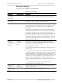
FXS (Foreign Exchange Subscriber)
TNV-2 Telecommunication Network Voltage-2:
Ports whose normal operating voltage exceeds the
limits of SELV (usually up to 120 VDC or telephone
ringing voltages), on which overvoltages from
telecommunication networks are not possible. These
ports are not permitted to be directly connected to
external telephone and data lines.
FXO (Foreign Exchange Office), xDSL
(with feeding voltage), U-Interface
ISDN
TNV-3 Telecommunication Network Voltage-3:
Ports whose normal operating voltage exceeds the
limits of SELV (usually up to 120 VDC or telephone
ringing voltages), on which overvoltages from
telecommunication networks are possible.
Safety Extra Low Voltage:
Ports which do not present a safety hazard. Usually
up to 30 VAC or 60 VDC.
Always connect a given port to a port of the same safety status. If in doubt, seek the assistance
of a qualified safety engineer.
Always make sure that the equipment is grounded before connecting telecommunication cables.
Do not disconnect the ground connection before disconnecting all telecommunications cables.
Some SELV and non-SELV circuits use the same connectors. Use caution when connecting cables.
Extra caution should be exercised during thunderstorms.
When using shielded or coaxial cables, verify that there is a good ground connection at both
ends. The grounding and bonding of the ground connections should comply with the local codes.
The telecommunication wiring in the building may be damaged or present a fire hazard in case of
contact between exposed external wires and the AC power lines. In order to reduce the risk,
there are restrictions on the diameter of wires in the telecom cables, between the equipment
and the mating connectors.
Caution
To reduce the risk of fire, use only No. 26 AWG or larger telecommunication line
cords.
Attention
Pour réduire les risques s’incendie, utiliser seulement des conducteurs de
télécommunications 26 AWG ou de section supérieure.
Some ports are suitable for connection to intra-building or non-exposed wiring or cabling only. In
such cases, a notice will be given in the installation instructions.
Do not attempt to tamper with any carrier-provided equipment or connection hardware.
Electromagnetic Compatibility (EMC)
The equipment is designed and approved to comply with the electromagnetic regulations of
major regulatory bodies. The following instructions may enhance the performance of the
equipment and will provide better protection against excessive emission and better immunity
against disturbances.
A good ground connection is essential. When installing the equipment in a rack, make sure to
remove all traces of paint from the mounting points. Use suitable lock-washers and torque. If an
external grounding lug is provided, connect it to the ground bus using braided wire as short as
possible.
The equipment is designed to comply with EMC requirements when connecting it with unshielded
twisted pair (UTP) cables. However, the use of shielded wires is always recommended, especially
for high-rate data. In some cases, when unshielded wires are used, ferrite cores should be
installed on certain cables. In such cases, special instructions are provided in the manual.
Disconnect all wires which are not in permanent use, such as cables used for one-time
configuration.
The compliance of the equipment with the regulations for conducted emission on the data lines
is dependent on the cable quality. The emission is tested for UTP with 80 dB longitudinal
conversion loss (LCL).
Unless otherwise specified or described in the manual, TNV-1 and TNV-3 ports provide secondary
protection against surges on the data lines. Primary protectors should be provided in the building
installation.
The equipment is designed to provide adequate protection against electro-static discharge (ESD).
However, it is good working practice to use caution when connecting cables terminated with
plastic connectors (without a grounded metal hood, such as flat cables) to sensitive data lines.
Before connecting such cables, discharge yourself by touching ground or wear an ESD preventive
wrist strap.
FCC-15 User Information
This equipment has been tested and found to comply with the limits of the Class A digital device,
pursuant to Part 15 of the FCC rules. These limits are designed to provide reasonable protection
against harmful interference when the equipment is operated in a commercial environment. This
equipment generates, uses and can radiate radio frequency energy and, if not installed and used
in accordance with the Installation and Operation manual, may cause harmful interference to the
radio communications. Operation of this equipment in a residential area is likely to cause harmful
interference in which case the user will be required to correct the interference at his own
expense.
Canadian Emission Requirements
This Class A digital apparatus meets all the requirements of the Canadian Interference-Causing
Equipment Regulation.
Cet appareil numérique de la classe A respecte toutes les exigences du Règlement sur le matériel
brouilleur du Canada.
Warning per EN 55022 (CISPR-22)
Warning
Avertissement
Achtung
This is a class A product. In a domestic environment, this product may cause radio
interference, in which case the user will be required to take adequate measures.
Cet appareil est un appareil de Classe A. Dans un environnement résidentiel, cet
appareil peut provoquer des brouillages radioélectriques. Dans ces cas, il peut être
demandé à l’utilisateur de prendre les mesures appropriées.
Das vorliegende Gerät fällt unter die Funkstörgrenzwertklasse A. In Wohngebieten
können beim Betrieb dieses Gerätes Rundfunkströrungen auftreten, für deren
Behebung der Benutzer verantwortlich ist.
Français
Mise au rebut du produit
Afin de faciliter la réutilisation, le recyclage ainsi que d'autres formes de
récupération d'équipement mis au rebut dans le cadre de la protection de
l'environnement, il est demandé au propriétaire de ce produit RAD de ne pas
mettre ce dernier au rebut en tant que déchet municipal non trié, une fois
que le produit est arrivé en fin de cycle de vie. Le client devrait proposer des
solutions de réutilisation, de recyclage ou toute autre forme de mise au rebut
de cette unité dans un esprit de protection de l'environnement, lorsqu'il aura
fini de l'utiliser.
Instructions générales de sécurité
Les instructions suivantes servent de guide général d'installation et d'opération sécurisées des
produits de télécommunications. Des instructions supplémentaires sont éventuellement
indiquées dans le manuel.
Symboles de sécurité
Ce symbole peut apparaitre sur l'équipement ou dans le texte. Il indique des risques
potentiels de sécurité pour l'opérateur ou le personnel de service, quant à
l'opération du produit ou à sa maintenance.
Avertissement
Danger de choc électrique ! Evitez tout contact avec la surface marquée tant que le
produit est sous tension ou connecté à des lignes externes de télécommunications.
Mise à la terre de protection : la cosse ou la borne marquée devrait être connectée
à la prise de terre de protection du bâtiment.
•
Avant la mise en marche de l'équipement, assurez-vous que le câble de fibre
optique est intact et qu'il est connecté au transmetteur.
•
Ne tentez pas d'ajuster le courant de la commande laser.
•
N'utilisez pas des câbles ou connecteurs de fibre optique cassés ou sans
terminaison et n'observez pas directement un rayon laser.
•
L'usage de périphériques optiques avec l'équipement augmentera le risque pour
les yeux.
•
L'usage de contrôles, ajustages ou procédures autres que celles spécifiées ici
pourrait résulter en une dangereuse exposition aux radiations.
ATTENTION : Le rayon laser peut être invisible !
Les utilisateurs pourront, dans certains cas, insérer leurs propres émetteurs-récepteurs Laser SFP
dans le produit. Les utilisateurs sont avertis que RAD ne pourra pas être tenue responsable de
tout dommage pouvant résulter de l'utilisation d'émetteurs-récepteurs non conformes. Plus
particulièrement, les utilisateurs sont avertis de n'utiliser que des produits approuvés par
l'agence et conformes à la réglementation locale de sécurité laser pour les produits laser de
classe 1.
Respectez toujours les précautions standards de sécurité durant l'installation, l'opération et la
maintenance de ce produit. Seul le personnel de service qualifié et autorisé devrait effectuer
l'ajustage, la maintenance ou les réparations de ce produit. Aucune opération d'installation,
d'ajustage, de maintenance ou de réparation ne devrait être effectuée par l'opérateur ou
l'utilisateur.
Manipuler des produits sous tension
Règles générales de sécurité
Ne pas toucher ou altérer l'alimentation en courant lorsque le câble d'alimentation est branché.
Des tensions de lignes peuvent être présentes dans certains produits, même lorsque le
commutateur (s'il est installé) est en position OFF ou si le fusible est rompu. Pour les produits
alimentés par CC, les niveaux de tension ne sont généralement pas dangereux mais des risques
de courant peuvent toujours exister.
Avant de travailler sur un équipement connecté aux lignes de tension ou de télécommunications,
retirez vos bijoux ou tout autre objet métallique pouvant venir en contact avec les pièces sous
tension.
Sauf s'il en est autrement indiqué, tous les produits sont destinés à être mis à la terre durant
l'usage normal. La mise à la terre est fournie par la connexion de la fiche principale à une prise
murale équipée d'une borne protectrice de mise à la terre. Si une cosse de mise à la terre est
fournie avec le produit, elle devrait être connectée à tout moment à une mise à la terre de
protection par un conducteur de diamètre 18 AWG ou plus. L'équipement monté en châssis ne
devrait être monté que sur des châssis et dans des armoires mises à la terre.
Branchez toujours la mise à la terre en premier et débranchez-la en dernier. Ne branchez pas des
câbles de télécommunications à un équipement qui n'est pas mis à la terre. Assurez-vous que
tous les autres câbles sont débranchés avant de déconnecter la mise à la terre.
Français
Certains produits peuvent être équipés d'une diode laser. Dans de tels cas, une
étiquette indiquant la classe laser ainsi que d'autres avertissements, le cas échéant,
sera jointe près du transmetteur optique. Le symbole d'avertissement laser peut
aussi être joint.
Avertissement
Veuillez observer les précautions suivantes :
Français
Connexion au courant du secteur
Assurez-vous que l'installation électrique est conforme à la réglementation locale.
Branchez toujours la fiche de secteur à une prise murale équipée d'une borne protectrice de mise
à la terre.
La capacité maximale permissible en courant du circuit de distribution de la connexion alimentant
le produit est de 16A. Le coupe-circuit dans l'installation du bâtiment devrait avoir une capacité
élevée de rupture et devrait fonctionner sur courant de court-circuit dépassant 35A.
Branchez toujours le câble d'alimentation en premier à l'équipement puis à la prise murale. Si un
commutateur est fourni avec l'équipement, fixez-le en position OFF. Si le câble d'alimentation ne
peut pas être facilement débranché en cas d'urgence, assurez-vous qu'un coupe-circuit ou un
disjoncteur d'urgence facilement accessible est installé dans l'installation du bâtiment.
Le disjoncteur devrait déconnecter simultanément les deux pôles si le système de distribution de
courant est de type IT.
Connexion d'alimentation CC
Sauf s'il en est autrement spécifié dans le manuel, l'entrée CC de l'équipement est flottante par
rapport à la mise à la terre. Tout pôle doit être mis à la terre en externe.
A cause de la capacité de courant des systèmes à alimentation CC, des précautions devraient
être prises lors de la connexion de l'alimentation CC pour éviter des courts-circuits et des risques
d'incendie.
Les unités CC devraient être installées dans une zone à accès restreint, une zone où l'accès n'est
autorisé qu'au personnel qualifié de service et de maintenance.
Assurez-vous que l'alimentation CC est isolée de toute source de courant CA (secteur) et que
l'installation est conforme à la réglementation locale.
La capacité maximale permissible en courant du circuit de distribution de la connexion alimentant
le produit est de 16A. Le coupe-circuit dans l'installation du bâtiment devrait avoir une capacité
élevée de rupture et devrait fonctionner sur courant de court-circuit dépassant 35A.
Avant la connexion des câbles d'alimentation en courant CC, assurez-vous que le circuit CC n'est
pas sous tension. Localisez le coupe-circuit dans le tableau desservant l'équipement et fixez-le
en position OFF. Lors de la connexion de câbles d'alimentation CC, connectez d'abord le
conducteur de mise à la terre à la borne correspondante, puis le pôle positif et en dernier, le
pôle négatif. Remettez le coupe-circuit en position ON.
Un disjoncteur facilement accessible, adapté et approuvé devrait être intégré à l'installation du
bâtiment.
Le disjoncteur devrait déconnecter simultanément les deux pôles si l'alimentation en courant CC
est flottante.
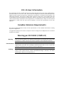
Declaration of Conformity
Manufacturer's Name:
RAD Data Communications Ltd.
Manufacturer's Address:
24 Raoul Wallenberg St., Tel Aviv 69719, Israel
declares that the product:
Product Name:
FCD-IP
conforms to the following standard(s) or other normative document(s):
EMC:
Safety:
EN 55022:1998
Information technology equipment – Radio
disturbance characteristics – Limits and
methods of measurement.
EN 50024: 1998
Information technology equipment – Immunity
characteristics – Limits and methods of
measurement.
EN 60950: 2000
Safety of information technology equipment.
Supplementary Information:
The product herewith complies with the requirements of the EMC Directive 89/336/EEC, the Low
Voltage Directive 73/23/EEC and the R&TTE Directive 1999/5/EC for wired equipment. The
product was tested in a typical configuration.
Tel Aviv, 28 November 2004
Haim Karshen
VP Quality
European Contact: RAD Data
Ottobrunn-Riemerling, Germany
Communications
GmbH,
Otto-Hahn-Str.
28-30,
85521
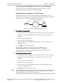
Quick Start Guide
Installation of FCD-IP should be performed only by an experienced technician. If
you are familiar with FCD-IP, use this guide to prepare the units for operation.
1.
Installing FCD-IP
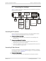
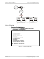
Connecting the Interfaces
³
To connect the interfaces:
1. Identify primary, secondary and user links installed in your FCD-IP.
2. Use the appropriate cable to connect all existing interfaces (primary and
secondary WAN links, sublinks, LAN, data, voice and ISDN ports), according to
your application.
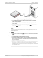
Connecting the Power
³
To connect the AC power:
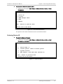
1. Check that the ON/OFF switch on the FCD-IP rear panel is set to OFF.
2. Connect the power cable to the connector on the FCD-IP rear panel.
3. Connect the power cable to the mains outlet.
³
To connect the DC power:
4. Check that the ON/OFF switch on the FCD-IP rear panel is set to OFF.
5. Refer to the DC power supply connection supplement.
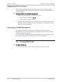
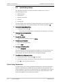
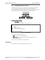
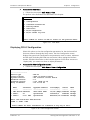
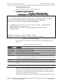
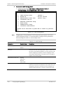
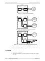
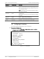
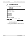
2.
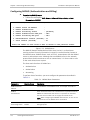
Configuring FCD-IP
Configure FCD-IP to the desired operation mode via an ASCII terminal connected
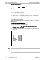
to the front panel CONTROL port.
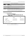
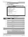
³
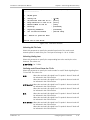
To start a terminal session:
1. Connect a terminal to the CONTROL connector of FCD-IP.
2. Turn on the control terminal PC and set its port parameters to 9,600 baud,
8 bits/character, 1 stop bit, no parity. Set the terminal emulator to ANSI
VT100 emulation (for optimal view of system menus).
3. Power FCD-IP up and proceed with the management session.
FCD-IP Ver. 4.2
Configuring FCD-IP
1
Quick Start Guide
Installation and Operation Manual
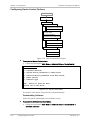
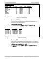
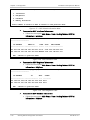
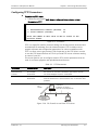
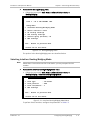
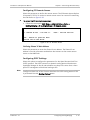
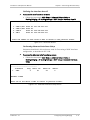
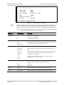
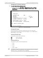
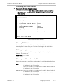
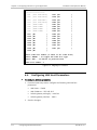
4. Enter the password. (The default password for first-time connection is 1234.
You can change or remove it later.)
The Main menu screen appears.
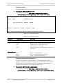
5. From the Main menu, select the Quick Setup menu or the Advanced Setup
menu, and configure FCD-IP according to your applications requirements.
2
Configuring FCD-IP
FCD-IP Ver. 4.2
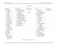
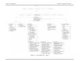
Contents
Chapter 1. Introduction 1.1 Overview.................................................................................................................... 1-1 Product Options...................................................................................................... 1-1 Applications ............................................................................................................ 1-2 Features ................................................................................................................. 1-5 1.2 Physical Description ................................................................................................... 1-7 1.3 Functional Description................................................................................................ 1-8 Main Link and Sublink Characteristics ...................................................................... 1-8 Data Channel Interfaces .......................................................................................... 1-9 System Timing Considerations ................................................................................. 1-9 Clock Recovery Behavior ......................................................................................... 1-9 Timeslot Handling ................................................................................................. 1-10 Ring Redundancy .................................................................................................. 1-10 Integrated Router ................................................................................................. 1-14 Bridging ................................................................................................................ 1-14 Protocols .............................................................................................................. 1-15 Management ........................................................................................................ 1-15 1.4 Technical Specifications............................................................................................ 1-16 Chapter 2. Installation and Setup 2.1 2.2 2.3 2.4 2.5 2.6 2.7 Introduction ............................................................................................................... 2-1 Site Requirements and Prerequisites .......................................................................... 2-1 Package Contents ...................................................................................................... 2-2 Equipment Needed..................................................................................................... 2-2 Setting the Internal Jumpers and Switches .................................................................. 2-2 Mounting the Unit ...................................................................................................... 2-2 Connecting the Interfaces .......................................................................................... 2-3 Connecting E1/T1 Interface ..................................................................................... 2-3 Connecting IO Data Channel .................................................................................... 2-3 Connecting the Control Port .................................................................................... 2-4 2.8 Connecting the Power ................................................................................................ 2-4 Fuses...................................................................................................................... 2-4 Connecting AC Power .............................................................................................. 2-5 Connecting DC Power.............................................................................................. 2-5 Chapter 3. Operation 3.1 Turning On the Unit ................................................................................................... 3-1 3.2 Indicators .................................................................................................................. 3-1 3.3 Configuration and Management Alternatives .............................................................. 3-4 Configuring FCD-IP via Terminal ............................................................................... 3-4 Configuring FCD-IP via Telnet .................................................................................. 3-6 Connecting via SNMP Management .......................................................................... 3-6 3.4 Turning FCD-IP Off ..................................................................................................... 3-6 Chapter 4. Configuration 4.1 Overview.................................................................................................................... 4-1 4.2 Main Menu ................................................................................................................. 4-5 FCD-IP Ver. 4.2
i
Table of Contents
Installation and Operation Manual
4.3 Quick Setup Menu ...................................................................................................... 4-6 Quick Setup Parameters .......................................................................................... 4-6 Quick Setup Menu Examples .................................................................................... 4-7 Configuring the WAN Interface .............................................................................. 4-10 Configuring the LAN Interface ............................................................................... 4-12 Configuring the ISDN Interface .............................................................................. 4-14 Configuring the Frame Relay Connections.............................................................. 4-14 Selecting the DLCI Number .................................................................................... 4-14 Configuring Asynchronous V.24 Interface .............................................................. 4-15 Configuring Security Options ................................................................................. 4-15 4.4 Configuring Security ................................................................................................. 4-15 Restricting Access to FCD-IP .................................................................................. 4-16 Configuring Firewall .............................................................................................. 4-18 Configuring IP Address Translation (NAT)............................................................... 4-21 4.5 Configuring Device Control ....................................................................................... 4-23 Setup Menu .......................................................................................................... 4-23 Configuring Device Control Options ....................................................................... 4-24 4.6 Viewing FCD-IP Configuration and Status .................................................................. 4-28 Displaying FCD-IP Configuration ............................................................................ 4-29 Displaying Interface Connections........................................................................... 4-30 Viewing Routing Tables ......................................................................................... 4-30 Chapter 5. Performing Advanced Setup 5.1 Defining Host Parameters .......................................................................................... 5-2 Entering Device ID................................................................................................... 5-3 Defining IP Host Parameters ................................................................................... 5-4 Defining SNMP Managers ........................................................................................ 5-6 Configuring TFTP Parameters................................................................................... 5-7 Configuring RADIUS (Authentication and Billing) ...................................................... 5-8 5.2 Configuring Routing/Bridging ...................................................................................... 5-9 Selecting Interface Routing/Bridging Mode ............................................................ 5-11 Defining Static Stations and Nets .......................................................................... 5-14 Setting IP Routing ................................................................................................. 5-15 Configuring IPX Routing......................................................................................... 5-24 Configuring Station Ageing .................................................................................... 5-26 Configuring NTP Settings....................................................................................... 5-26 5.3 Configuring the Interfaces ........................................................................................ 5-27 5.4 Configuring Link Parameters ..................................................................................... 5-29 5.5 Configuring LAN Parameters ..................................................................................... 5-31 5.6 Configuring E1/T1 Interfaces .................................................................................... 5-31 T1 Features .......................................................................................................... 5-32 E1 Features .......................................................................................................... 5-33 5.7 Configuring the T1 Interface ..................................................................................... 5-34 Configuring T1 Link Parameters ............................................................................. 5-36 Configuring Additional Card Parameters................................................................. 5-38 Advanced Setup Menu .......................................................................................... 5-45 5.8 Configuring E1 Interface ........................................................................................... 5-48 Defining E1 Link Parameters ................................................................................. 5-51 Defining Additional Card Parameters ..................................................................... 5-52 Advanced Setup Menu .......................................................................................... 5-59 Configuring the ISDN Interface .............................................................................. 5-61 Configuring the Frame Relay Interface ................................................................... 5-63 ii
FCD-IP Ver. 4.2
Installation and Operation Manual
Table of Contents
5.9 Configuring Access Control (Security) ....................................................................... 5-68 Defining External Access Security (only Relevant to Link with PPP Protocol) ........... 5-69 Defining Device Security Identity (PPP only)........................................................... 5-70 Configuring Security Host/Guest (PPP only) ........................................................... 5-71 Defining Login Script ............................................................................................. 5-71 5.10 Configuring WAN Economy ....................................................................................... 5-73 Defining Filters ..................................................................................................... 5-75 Configuring Connection on Demand ...................................................................... 5-82 Defining Spoofing ................................................................................................. 5-86 5.11 Resetting FCD-IP to the Defaults .............................................................................. 5-88 Chapter 6. Configuring FCD-IP for a Typical Application 6.1 Overview.................................................................................................................... 6-1 Application ............................................................................................................. 6-1 Guidelines for Configuring FCD-IP ............................................................................ 6-1 6.2 Configuring the WAN Interface ................................................................................... 6-2 6.3 Configuring E1 Parameters ......................................................................................... 6-3 6.4 Configuring LAN Host Parameters ............................................................................... 6-4 Chapter 7. Troubleshooting and Diagnostics 7.1 Monitoring Performance ............................................................................................. 7-1 Displaying Statistics ................................................................................................ 7-1 Displaying E1/T1 Diagnostics ................................................................................... 7-2 Displaying E1/T1 Alarms Log File ............................................................................. 7-4 7.2 Alarm Collection and Reporting .................................................................................. 7-5 Alarm Buffer ........................................................................................................... 7-5 Alarm Display .......................................................................................................... 7-5 Setting the T1 Alarm Filter ...................................................................................... 7-6 Setting the E1 Alarm Filter ...................................................................................... 7-6 Alarm Messages ...................................................................................................... 7-7 7.3 General Troubleshooting .......................................................................................... 7-10 7.4 Pinging Remote Hosts .............................................................................................. 7-10 7.5 E1/T1 and Voice Troubleshooting ............................................................................. 7-12 7.6 Router Connections Troubleshooting ........................................................................ 7-12 IP connection to LAN is Down ............................................................................... 7-12 IP Connection to WAN is Down.............................................................................. 7-12 7.7 Performing T1 Diagnostics........................................................................................ 7-14 Running Loopbacks ............................................................................................... 7-14 Using Voice Diagnostic Tools ................................................................................. 7-17 7.8 Performing E1 Diagnostics........................................................................................ 7-17 Running Loopbacks ............................................................................................... 7-18 Using Voice Diagnostic Tools ................................................................................. 7-19 7.9 Frequently Asked Questions ..................................................................................... 7-20 7.10 Technical Support .................................................................................................... 7-21 Appendix A. Interface Specifications and Pinouts Appendix B. Boot Manager Appendix C. SNMP Management Appendix D. Glossary FCD-IP Ver. 4.2
iii
Table of Contents
iv
Installation and Operation Manual
FCD-IP Ver. 4.2
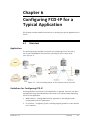
Chapter 1
Introduction
1.1
Overview
FCD-IP is an E1/T1 or fractional E1/T1 Integrated Access Device (IAD), which
enables service providers to bundle voice and Internet access services over a
single E1 or T1 access line. FCD-IP connects an Ethernet LAN to the Internet or
Intranet through the integrated IP/IPX router or bridge. The connection is made
via E1/T1 links, operating at data rates of up to 2.048 Mbps for E1, 1.544 Mbps
for T1 with optional backup for data using E1/T1, ISDN or PSTN networks. WAN
data protocols supported are Frame Relay, PPP and MLPPP. FCD-IP also supports
two Ethernet LAN connections, or a four port switch.
FCD-IP provides transparent data and voice capabilities over the E1 or T1 access
line, such as a synchronous data channel that supports user-selectable
transmission rates, digital voice over sub E1 or T1 link that supports PBX and
analog FXS, FXO and E&M voice ports.
Product Options
There are several versions of FCD-IP, and each version has its own specific
options.
The following options are available for ordering as part of FCD-IP:
•
•
FCD-IP Ver. 4.2
Main WAN Interface
E1/T1 Interface (one or two links)
Sub-E1/T1, analog voice, and ISDN backup interface options:
S: supports sub-E1/T1 (up to three interfaces)
FXS: supports 4 FXS voice channels
FXO: supports 4 FXO voice channels
E&M: supports 4 E&M voice channels
IBE: supports ISDN “S” interface
IBU: supports ISDN “U” interface.
WAN interface options (up to two data ports):
T1 or fractional T1 CSU/DSU operating at up to 1.544 Mbps
E1 or fractional E1, with or without LTU, operating at up to 2.048 Mbps
E1/T1 over fiber optic links with interfaces:
Overview
1-1
Chapter 1 Introduction
Installation and Operation Manual
•
Note
850 nm LED for use over multimode fiber at distances up to 5 km
(3 miles)
1310 nm LED for use over single mode fiber at distances up to 47 km
(29 miles)
1310 nm laser diode for use over single mode fiber at distances up to
62 km (38 miles)
1550 nm laser diode for use over single mode fiber for extended
range up to 100 km (62 miles).
Data port interfaces:
V.35 with 34-pin female via adapter cable
V.24/RS-232 or RS-530 with 25 pin D-type, female
X.21 with 15-pin D-type, female via adapter cable
V.36/RS-422 with 37-pin D-type, female via adapter cable.
LAN interface options:
One 10/100BaseT port with RJ-45 connector (UTP)
Two 10BaseT ports with RJ-45 connector (UTP).
4-port 10/100BaseT switch.
Only two links are supported, which limits the configuration options. For example,
the second WAN option is not available when configuring E1/T1 with an ISDN
backup.
The dual LAN configuration is not available when configuring E1/T1 with an ISDN
backup.
Applications
FCD-IP is the solution for several different applications. Order your unit according
to your specific application requirements. FCD-IP can be used as a router for the
office LAN to access the Internet/intranet and at the same time control access
from the local PBX to the E1/T1 line. FCD-IP can also have up to four telephones
connected directly to the unit for those applications where a PBX is not present.
1-2
Overview
FCD-IP Ver. 4.2
Installation and Operation Manual
Chapter 1 Introduction
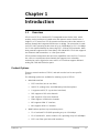
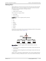
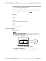
The following is a list of application options for FCD-IP:
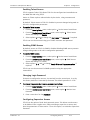
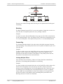
FCD-IP with PBX and LAN - In the application shown in Figure 1-1,
FCD-IP supports a single LAN connection to the Internet/Intranet and voice
connectivity to the PSTN.
Figure 1-1. FCD-IP with PBX and LAN
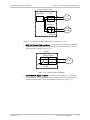
FCD-IP with four Telephones and LAN – In the application shown in Figure 1-2,
FCD-IP supports four individual telephones connected to the carrier, and a LAN
connection to the Internet/Intranet.
Figure 1-2. FCD-IP with Four Telephones and LAN over E1
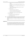
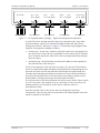
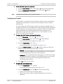
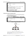
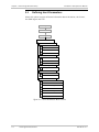
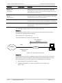
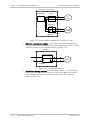
FCD-IP with Chain Configuration - Figure 1-3 shows the FCD-IP in a chain
configuration. When this mode is configured, the FCD-IP has two links, which
means traffic from any data timeslot of each link is passed to the integrated
router/bridge. This allows you to concatenate any number of FCD-IP devices (the
last one possibly working in Normal mode since it has only one E1/T1 uplink),
using only one E1/T1 line between each pair, and still be able to share data
timeslots of any device with any other device in the chain.
Note
FCD-IP Ver. 4.2
In order to configure Chain mode, the device must have at least two E1/T1
interfaces (labeled Main and Sub1 or Sub1/Link2, on the rear panel), and Link 2
resources cannot be used by other link (such as ISDN or DTE card) or by a second
LAN.
Overview
1-3
Chapter 1 Introduction
Installation and Operation Manual
Figure 1-3. FCD-IP with One Telephone and LAN Using a Chain Configuration
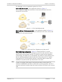
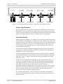
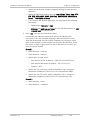
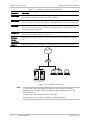
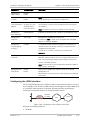
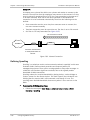
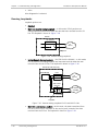
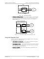
FCD-IP with RAD Ring Configuration - Figure 1-4 shows the RAD Ring solution.
This unique application provides virtually immediate recovery of all services in
case of failure of any single E1 interface.
Two failures at the same time mean that some of the devices are disconnected
from the ring. However, services between devices that are still connected will
continue to operate.
In case of PPP failure while E1 lines are still up, services will reestablish, but in
some cases it might take a few seconds for the devices to realize that PPP is
down.
The user may select one of two mechanisms (Wait To Restore and Recovery
Timeout) to determine how much time the devices should wait before reusing an
E1 line that failed. This feature prevents the use of unstable E1 lines.
When connecting devices in a ring, the main link must be connected to the SUB 1
of its peer. An improper connection will cause an alarm, helping the user to
properly connect the devices.
Ring Plus Shared LAN configuration is an enhancement to Ring configuration.
When configured, the device has two E1 links, which means that each data
timeslot, from either link, is passed to the integrated router/bridge. This enables
you to share data timeslots throughout the entire ring, each device taking the
data relevant to it, and passing the rest forward.
In Ring configuration, data timeslots can be configured only between two of the
Ring devices and all the others must pass through transparently. On the other
hand, in Ring Plus Shared LAN mode, the same data timeslots can be configured
on two or more Ring devices, all sharing the same bandwidth, which saves on
expensive E1 lines. This mode allows each machine on any LAN connected to a
Ring device, to send data to any other machine; hence the name Shared LAN.
Note
• In order to configure Ring Plus Shared LAN mode, the device must contain at
least two E1 interfaces (labeled Main and Sub1/Link2 on the rear panel) and
Link 2 resources cannot be used by another link (such as ISDN or DTE card) or
by a second LAN.
• The Ring can consist of FCD-IP devices and any other RAD device that supports
Ring configuration (such as Megaplex).
• In this version, Ring and Ring Plus Shared LAN can be configured on E1 only.
1-4
Overview
FCD-IP Ver. 4.2
Installation and Operation Manual
Chapter 1 Introduction
Figure 1-4. FCD-IP with Ring or Ring Plus Shared LAN Configuration
Features
E1/T1 Main Link
•
E1/T1 Integrated Access Device (IAD) for Internet/intranet and voice
connectivity
•
Integral E1 with or without LTU or Integral T1 CSU/DSU
•
Up to three sub-E1/T1 drop and insert port for PABX connectivity; one of
them can serve as second link
•
Fail-safe bypass for the sub-E1/T1 link (not available for the fiber optic main
link)
•
Optional fiber optic uplink
•
ISDN uplink.
Integrated Router
FCD-IP Ver. 4.2
•
IP and IPX routing and standard bridging
•
Supports Frame Relay, PPP and MLPPP
Overview
1-5
Chapter 1 Introduction
Installation and Operation Manual
•
One or two Ethernet ports, one Fast Ethernet port, or a four port Fast
Ethernet switch
•
Optional dial-up or integrated ISDN backup
•
PAP/CHAP authentication
•
Solid Firewall protection
•
NAT and Single IP address translation
•
DHCP server and relay
•
OSPF Protocol
•
RIP1 and RIP2 Protocols
•
NTP support (for time and date learning from the network)
•
Gratuitous ARP
•
Quick setup and configuration
•
Dual in-band and out-of-band remote management
•
SNMP and Telnet support
•
Dual management authorization levels (carrier/user)
•
Flash memory for software and parameter file downloading
•
Remote software and parameter file download.
Ethernet/Fast Ethernet Switch
•
Built-in 4-port switch with 1Mb buffer with Auto-polarity and autonegotiation.
Data
•
Optional second data port (transparent N × 64/56 kbps or serial router port).
Voice
1-6
•
Supports four analog voice channels
•
PCM encoded, A-Law or μ-Law
•
Optional interfaces: 2-wire FXS, 2-wire FXO, or 4-wire or 2-wire E&M.
Overview
FCD-IP Ver. 4.2
Installation and Operation Manual
1.2
Chapter 1 Introduction
Physical Description
FCD-IP units are delivered completely assembled. The units are designed for
desktop installation, or to be mounted in a 19-inch rack. Installation procedures
for FCD-IP models and respective versions are provided in Chapter 2.
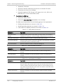
Figure 1-5 shows a 3-D diagram of FCD-IP.
Figure 1-5. FCD-IP General View
Controls and indicators of the various versions of FCD-IP and their functions are
described in Chapter 3. The LED indicators on the front panel indicate the
operating status of FCD-IP. Various indicators display status of user’s data port,
status of data activity in user’s data connector, and alert conditions. For a
description of the front panel, refer to Chapter 3.
The power and interface connectors are located on the rear panel of FCD-IP. For
a description of the rear panel, refer to Chapter 2.
The internal jumpers of FCD-IP are set according to options ordered. There is no
need to change any of the jumpers.
FCD-IP Ver. 4.2
Physical Description
1-7
Chapter 1 Introduction
Installation and Operation Manual
1.3
Functional Description
This section describes the main and sublink characteristics, the data and voice
channel interfaces, timing considerations, time slot handling, integrated IP router
and management of FCD-IP. Figure 1-6 shows a functional block diagram for
FCD-IP.
Figure 1-6. FCD-IP Functional Block Diagram
FCD-IP can be ordered in several configuration options. A main link is always
E1/T1, and there is always at least one LAN link. The other interfaces may be a
sub E1/T1, analog voice, ISDN backup or n x 64 data port.
Main Link and Sublink Characteristics
FCD-IP can contain up to four E1/T1 interfaces; one or two of them can be links
(that is, incoming traffic from these links is passed though the integrated
router/bridge). While link 1 always exists, you can configure link 2 when the
following conditions are met:
1-8
•
The device has at least two E1/T1 interfaces on the rear panel, labeled Main
and Sub1, or Main and Sub1/Link2
•
Link 2 is not occupied by other hardware (for example, ISDN or DTE card)
•
LAN 2 does not exist.
Functional Description
FCD-IP Ver. 4.2
Installation and Operation Manual
Chapter 1 Introduction
The FCD-IP E1 main and sublink meet the requirements of ITU-T Rec. G.703,
G.704, G.706, G.732, and G.823, and support 256N and 256S multiframes
(2 or 16 frames per multiframe, respectively), in accordance with ITU-T Rec.
G.704. For FCD-IP T1 versions the main and sublink comply to AT&T TR62411 and
ANSI T1.403 standards, and support D4 and ESF framing.
The framed mode and use of the CRC-4 function are user-selectable.
The main and sublink line interfaces:
For E1:
•
120Ω balanced line interface, terminated in an RJ-48C eight-pin (ISO 10173)
connector
•
Using an adapter cable, the E1 can be converted to a 75Ω unbalanced
interface, terminated in two BNC coaxial connectors.
For T1:
•
100Ω balanced interface.
You can select the E1 interface to activate the LTU option. With the T1 version,
you can choose to activate CSU or DSU.
When a power failure occurs, the failsafe bypass of the sub E1/T1 link ensures
the continuity of voice services between the main and the sublink.
Note
The fail-safe bypass of the E1/T1 sub-link is not available for the FCD-IP units
equipped with fiber optic E1/T1 interface.
Data Channel Interfaces
The data channel can be operated in several ways:
•
•
As n × 64 kbps or n × 56 kbps data port (DCE only)
As serial router port that supports IP/IPX routing and bridge over PPP or
Frame Relay (DTE only).
System Timing Considerations
Internally, FCD-IP uses one system timing source (clock). This system clock
determines the transmit timing of all the E1 links and data ports. The clock source
options are as follows:
•
Main link (each of them)
•
Sublink (each of them)
•
Internal.
Clock Recovery Behavior
When the clock source is configured as Internal, the clock source remains the
same regardless of the state of the interfaces. However, when one or more
interface is configured as the clock source, FCD-IP takes the following steps, upon
failure, to provide the device with an alternative clock source:
FCD-IP Ver. 4.2
Functional Description
1-9
Chapter 1 Introduction
•
Installation and Operation Manual
Normal and Chain application modes:
•
FCD-IP automatically reverts to the internal clock. It switches back to
deriving its clock from that interface as soon as the interface is up again.
Ring and Ring + Shared LAN application modes:
Upon failure of a non-Ring interface (that is, Sub 3 or Sub 4), FCD-IP
behaves the same as in Normal mode (see above).
Upon failure of a Ring interface (that is, Main or Sub1), FCD-IP takes the
clock source from the other Ring interface. If both are down, it switches
to the internal clock. When the interface is up again, it provides the clock
as originally configured.
Timeslot Handling
FCD-IP allows the user to configure each of the individual time slots freely
according to the following options:
•
Data Link 1 – in Normal and Ring modes, for data from router/bridge
•
Data Link 1+2 – in Chain and Ring + Shared LAN modes, for data from
router/bridge (in this case, the device has two E1/T1 links)
•
SUB Voice – for voice from sublink
•
SUB Data – for data from sublink
•
Voice (1, 2, 3, 4) – for analog voice port 1, 2, 3, 4.
For more information on configuring timeslots, refer to Chapter 4.
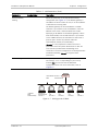
Ring Redundancy
Ring Redundancy is a proprietary RAD topology that provides higher availability
for critical applications. This topology is based on the use of two transmission
paths, each requiring a single twisted pair. Therefore, ring redundancy can use
the same cabling infrastructure as a regular point-to-point link. The two pairs
form a closed dual-ring topology, similar to the topology implemented in SDH
transmission networks: one path propagates data “clockwise” and the other
“counterclockwise”. In this manner, each FCD-IP can receive data through two
different paths, and selects only the signal received through one of the paths for
processing.
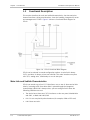
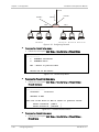
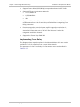
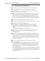
You can implement this topology using the FCD-IP’s Main and Sub1 E1 ports. The
following figure shows a typical application using the Ring Redundancy topology.
1-10
Functional Description
FCD-IP Ver. 4.2
Installation and Operation Manual
TS 1-3 Local
TS 4-13 Bypass
TS 1-13 Local
RX
Main
TX
RX
Sub1
RX
TX
Chapter 1 Introduction
TX
Main
TX
RX
Sub1
RX
A
(3TS)
A B C D E F
User's Equipment
Local
TS 4-7
TS 1-3, 8-13 Bypass
User's Equipment
TX
Main
TX
Local
TS 8-10
TS 1-7, 11-13 Bypass
RX
Sub1
RX
B
(3TS)
User's Equipment
TX
Main
TX
TS 11-13 Local
TS 1-10 Bypass
RX
Sub1
RX
C
(3TS)
User's Equipment
TX
Main
TX
Sub1
RX
F
(3TS)
User's Equipment
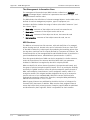
Figure 1-7. E1 Ring Redundancy Topology – Signal Flow during Normal Operation
In each FCD-IP unit, the Main and Sub1 ports are connected to the ring. Under
normal conditions, each FCD-IP transmits through the Main link and receives
through the Sub1 link. Therefore, in Figure 1-7 the primary ring propagates data
clockwise. The payload is handled as follows:
•
Primary ring – at each unit, timeslots used by the local unit are dropped from
the receive side of the Sub1 port, and added to the transmit side of the Main
port. Timeslots used by the other FCD-IP units are bypassed directly between
these two ports.
•
Secondary ring – all the timeslots received by the Main port are bypassed to
the transmit side of the Sub1 port.
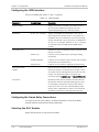
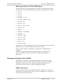
If one of the segments in the ring fails (see Figure 1-8), the two FCD-IPs detect
the loss of signal and change the signal routing within the corresponding units so
that each unit now receives and transmits only through the synchronized port.
Timeslots previously bypassed between the ports are now transferred between
the receive and transmit sides of the active port (by creating a special internal
local loopback), thereby preserving transmission path continuity.
The ring can sense a PPP failure between two devices even if both E1 lines remain
up, but it may take a few seconds to do so. Since both E1 lines are still up, the
clocking system is not affected by such a failure, unlike the case of a
nonfunctional E1 line.
Note that all other FCD-IP units do not need to change their operating
configuration; only the units that are connected to the failed segment must take
action in response to the failure.
FCD-IP Ver. 4.2
Functional Description
1-11
Chapter 1 Introduction
TS 1-13 Local
RX
Main
TX
Installation and Operation Manual
TS 1-3 Local
TS 4-13 Bypass
TX
Sub1
RX
Main
TX
Sub1
TX
RX
TS 4-7
Local
TS 1-3, 8-13 Bypass
RX
User'sEquipment
User'sEquipment
Sub1
RX
TX
A
(3 TS)
A B C D E F
TX
RX
Main
TS 11-13 Local
TS 1-10 Bypass
TS 8-10
Local
TS 1-7, 11-13 Bypass
B
(3 TS)
User'sEquipment
RX
Main
TX
Sub1
TX
RX
C
(3 TS)
User'sEquipment
RX
Main
TX
Sub1
TX
RX
F
(3 TS)
User'sEquipment
Figure 1-8. E1 Ring Redundancy Topology – Signal Flow after Segment Failure
Double Loop Detection
During a single failure in a ring system, all services continue as usual. In case of
dual failures, the ring is split into two parts. Services terminating in devices that
reside in the same segment continue, while services between devices on different
segments stops until at least one of the failed E1 lines is reestablished.
Clock Distribution
When using Ring Redundancy, it is necessary to ensure that the reference timing
is distributed in a controlled way to all the units in the network. This requires the
selection of one device in the ring as the clock source. That is, its clock should be
configured as ‘Internal’ (or ‘Sub2’ or ‘Sub3’ when it takes it’s clock from one of
these interfaces). All remaining devices in the ring must take their clock from
either the Main or Sub1 link.
You must ensure that the following configuration does not occur: one device’s
clock source is configured as ‘Main’ while the one connected to its Main link is
configured as ‘Sub 1’ (or vice versa).
It is recommended that half of the devices in the ring (those closer to the Main
link of the device which is used as the clock source), be configured to take their
clock from ‘Link 1’ (i.e. Main), while the other half be configured to take their
clock from ‘Sub1’.
The device that is configured to supply clock to the ring (‘Internal’, ‘Sub2’, or
‘Sub3’) never changes its clock source. All other devices change automatically,
from Main to Sub1 or vice versa, when the link from which they receive clock
fails. When the link recovers, the clock source returns to normal.
A propriety protocol is used by each device, when one of its links fails, to notify
peer devices. Peer devices also need to change their clock source, in case they
were receiving their clock from the same side on which the link failed. This
protocol runs over the inband management links.
In a situation where both of a device’s links fail: if the device is configured to
take its clock from ether Main or Sub1, it switches to Internal clock until one of
its links recovers.
1-12
Functional Description
FCD-IP Ver. 4.2
Installation and Operation Manual
Chapter 1 Introduction
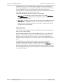
Figure 1-9 and Figure 1-10 show the timing reference flow before and after
recovery.
Sub1: Master
Main: Fallback
RX
TX
RX
Sub1
Main
RX
TX
TX
RX
Sub1
Main
TX
RX
TX
RX
Sub1
Main
TX
RX
Main
TX
TX
RX
Sub1
RX
Main
TX
TX
Sub1
RX
Clock
Reference
(Station)
Figure 1-9. E1 Ring Redundancy Topology – Normal Timing Reference Flow
Sub1: Master
Main: Fallback
RX
Main
TX
RX
Sub1
Main
TX
RX
TX
TX
Sub1
RX
RX
Main
TX
TX
Sub1
RX
RX
Main
TX
TX
Sub1
RX
RX
Main
TX
TX
Sub1
RX
RING CLOCK FAILURE
Clock
Reference
(Station)
Figure 1-10. E1 Ring Redundancy Topology – Timing Reference Flow after Segment Failure
To prevent unstable lines from constantly changing clock sources and
opening/closing loops, the user may choose between two mechanisms:
Recovery Timeout – If a ring interface fails, it is considered ‘down’ for the
period of the recovery timeout, even if it recovers before the timeout is
reached. After the timeout expires, the actual state of the interface is
tested. If the link is up, the appropriate actions are taken.
Wait To Restore –If a ring interface fails, it is considered ‘down’ until it
recovers during the WTR period and no alarm has occurred. Each alarm zeros
the WTR timer.
The default value for the recovery timeout is 12 seconds, and for the WTR is 300
seconds.
FCD-IP Ver. 4.2
Functional Description
1-13
Chapter 1 Introduction
Note
Installation and Operation Manual
A ring may comprise up to 66 devices.
All the devices in a ring should use the same mechanism and the same timeout
values.
For proper operation of the ring, enable Inband Management on the Main link and
Sub1 link (in the E1 Advanced Setup menu).
In Megaplex terminology, the main link of FCD-IP is the ‘primary’ port. When
connecting an FCD-IP to a Megaplex in a Ring topology, it is important that the
FCD-IP’s main link be connected to the Megaplex’s secondary port, and the
FCD-IP’s Sub1 link be connected to the Megaplex’s primary port.
Alarms are generated to alert the user when the ring is misconnected (main link
connected to main link or Sub1 to Sub1).
Integrated Router
IP Router
FCD-IP as an IP router supports:
•
Static IP net configuration
•
Dynamic IP net learning using OSPF, RIP-1 and RIP-2 protocols
•
CIDR topologies
•
Multiple IP nets on the LAN
•
Numbered and unnumbered interfaces
•
IP fragmentation
•
Gratuitous ARP
IPX Router
FCD-IP also supports standard IPX routing that includes support for RIP and SAP.
Bridging
FCD-IP supports bridging. The bridge is used to interconnect a number of LANs by
accessing layer 2 (MAC layer). FCD-IP automatically extends the scope of any
interface, allowing the interface to interconnect several networks, providing that
all supported interfaces are set to bridge mode.
FCD-IP interconnects:
•
Any LAN to link
•
Two LANs of the same Bridge
•
Two LANs and link.
FCD-IP interconnects all of its interfaces to one extended LAN.
FCD-IP supports standard bridging, as specified in IEEE 802.1D, and can operate
opposite any other third party bridge. Spanning Tree Algorithm is not supported.
1-14
Functional Description
FCD-IP Ver. 4.2
Installation and Operation Manual
Chapter 1 Introduction
Bridging works over PPP, Frame Relay RFC-1490 and also a ‘Native’ protocol. MAC
frames pass in an HDLC format.
Protocols
FCD-IP supports:
•
PPP (Point to Point Protocol) – this protocol supports a variety of links and
connection options
•
Frame Relay – a network interface, which provides high-speed frame or
packet transmission with minimum delay and maximum bandwidth utilization.
Management
FCD-IP features a variety of inband and out-of-band management options. These
options include dedicated time slot, dedicated DLCI, and dial-in connectivity.
You can manage the following capabilities:
•
FCD-IP configuration
•
Viewing FCD-IP status
•
Testing FCD-IP
•
Viewing alarm status and history.
The management functions are performed via:
•
SNMP management – enables management using the RADview or any other
standard SNMP-based management systems.
•
Telnet – enables a remote IP host to control the operation of FCD-IP using
functions identical to those provided by a supervision terminal.
•
Supervision terminal – an ASCII terminal connected to the RS-232 control port
of FCD-IP (or a PC running a terminal emulation program) can be used as a
supervision terminal.
Undesired access to FCD-IP via Telnet or SNMP can be blocked by the firewall, or
password protected. The dual-level management authentication allows access to
router configuration parameters while restricting the access to network
configuration parameters.
Software download is available via the control port using XMODEM and via
LAN/WAN using TFTP. Parameter file download and upload is available via LAN or
WAN using TFTP.
FCD-IP has an alarm history memory that holds the up to 100 alarms.
Management Using Dedicated Timeslot (DTS)
FCD-IP features out-of-band management through a dedicated timeslot.
The DTS is a management channel that connects directly to the FCD-IP host using
a separate IP interface, i.e. address, and operates as an additional WAN interface
connected to the management IP network.
FCD-IP Ver. 4.2
Functional Description
1-15
Chapter 1 Introduction
Installation and Operation Manual
This management channel is totally separated from the IP traffic that the
integrated router forwards, so there is no way to expose the manager IP network
to unauthorized IP users.
The DTS channel should be synchronized with other equipment such as a
cross-connect unit or router. This can be done with standard WAN protocols such
as Frame Relay and PPP.
In Chain or Ring + Shared LAN modes, when two links exist, in-band dedicated
timeslot management is configurable independently on either link.
Management traffic has priority over any other incoming and outgoing traffic, in
order to enable smooth management even under heavy traffic conditions. Yet
there is no risk of the device being bombarded by too much management traffic,
exploiting the priority of management traffic, to prevent any other traffic from
being handled; dedicated timeslot bandwidth is limited by its nature to
64 kbps x 2 (in a worse case scenario, if it is enabled on both E1/T1 links). This
prevents the device from being saturated with management traffic.
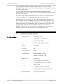
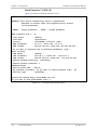
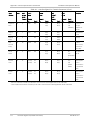
1.4
E1 Link Interface
Technical Specifications
Framing Options
256N (no MF, CCS)
256N (no MF, CCS) with CRC-4
256S (TS16 MF, CAS)
256S (TS16 MF, CAS) with CRC-4
Bit Rate
2.048 Mbps
Line Code
AMI
Zero Suppression
HDB3
Line Impedance
Balanced interface: 120Ω
Unbalanced interface: 75Ω
Signal Levels
Receive level:
• FCD-IP with LTU: 0 to –30 dB
• FCD-IP without LTU: 0 to –12 dB
Transmit level:
• Balanced interface: ±3V ±10%
• Unbalanced interface: ±2.37V ±10%
Jitter Performance
1-16
Technical Specifications
As per ITU-T Rec. G.823
FCD-IP Ver. 4.2
Installation and Operation Manual
Connectors
Chapter 1 Introduction
Balanced interface: RJ-45 8-pin
Unbalanced interface: Two BNC coaxial
(via adapter cable)
T1 Link Interface
Compliance
ITU G.703, G.704, G.706, G.732
Diagnostics
User activated local and remote loopbacks
Framing Options
D4
ESF
Bit Rate
1.544 Mbps
Line Code
AMI
Zero Suppression
Transparent
B7ZS
B8ZS
Impedance
Balanced: 100Ω
Signal Level
Receive level:
• FCD-IP with CSU: 0 to –36 dB
• FCD-IP without CSU: 0 to –10 dB
Transmit level:
• FCD-IP with CSU: 0, -7.5, -15, -22.5 dB
• FCD-IP without CSU: soft adjustable at 0
to 655 ft.
Jitter Performance
As per AT&T TR-62411
Connectors
RJ-45 8-pin, balanced
Compliance
AT&T TR62411, ANSI T1.403
Diagnostics
User available local and remote loopbacks
Network activated loops and FDL loops (RLB,
LLB)
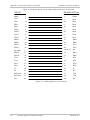
Analog Voice
Number of Voice
Channels
4 per card
Modulation Method
PCM (per ITU-T G.711 and AT&T PUB-43801)
μ-Law or A-Law
FCD-IP Ver. 4.2
Technical Specifications
1-17
Chapter 1 Introduction
Installation and Operation Manual
Interfaces
E&M: 2-wire or 4-wire, supporting different
types of E&M signaling: RS-464 Types I, II,
III, and V, and BT SSDC5, configured by
software
FXS: Loop start, WINK start (reverse polarity)
for direct connection to a 2-wire telephone
FXO: Loop start, WINK start (reverse
polarity) for connection to a 2-wire
telephone exchange subscriber line
Nominal level: 0 dBm
Nominal impedance: 600Ω
Return loss (ERL): Better than 18 dB
Frequency response: (Ref: 1020 Hz)
• ±0.5 dB, 300 to 3000 Hz
• ±1.1 dB, 250 to 3400 Hz
Signal to total distortion, G.712, G.713
method 2:
• 0 to –30 dBm0, better than 33 dB
• +3 to –45 dBm0, better than 22 dB
Idle channel noise: Better than –70 dBm0
(+20 dBrnc)
Transformer isolation: 1500 VRMS
Diagnostics
Remote analog loopback towards the
remote side, activated from local side
1kHz tone injection towards analog side
Activity indicators
Connectors
• E&M: RJ-45, 8-pin
• FXS, FXO: RJ-11, 6-pin
1-18
Technical Specifications
FCD-IP Ver. 4.2
Installation and Operation Manual
ISDN
Chapter 1 Introduction
Interfaces
ISDN BRI, “S” and “U”
Compliance
ETS 300012
I.430
NT1
5ESS
DMS-100
NI1
WAN Protocols
Types
Frame Relay – RFC 1490
PPP and MLPPP
Routing
Types
STATIC
RIP-1
RIP-2
OSPF
LAN Interface
Number of Ports
1, 2 or 4
Compliance
IEEE 802.3
Types
• Single 10/100BaseT (RJ-45) port
• Dual 10BaseT (RJ-45)
• 4-port 10/100BaseT (RJ-45) switch
Data Port Interfaces
Interfaces/Connectors
V.35 with 34-pin female via adapter cable
V.24/RS-232 or RS-530 with 25-pin D-type
female
X.21 with 15-pin D-type female via adapter
cable
V.36/RS-422 with 37-pin D-type female via
adapter cable
Fiber Optic Interfaces
Interface Options
850 nm LED
1310 nm LED
1310 nm laser diode
1550 nm laser diode
Connectors
ST
FC/PC
SC
Compliance
FCD-IP Ver. 4.2
ITU G.921, G.956
Technical Specifications
1-19
Chapter 1 Introduction
Indicators
Physical
Installation and Operation Manual
PWR (green)
Power status
READY (green)
Self-test result
LAN 1 DATA (yellow)
LAN 1 data transmit/receive status
LAN 2 DATA (yellow)
LAN 2 data transmit/receive status
LINK 1 DATA (yellow)
Link 1 data transmit/receive status
LINK 2 DATA (yellow)
Link 2 data transmit/receive status
LAN 1 ERR (red)
LAN 1 error status
LAN 2 ERR (red)
LAN 2 error status
LINK 1 ERR (red)
Link 1 error status
LINK 2 ERR (red)
Link 2 error status
LINK1 RED ALARM
(red)
Link 1 red alarm status (T1 only)
SUB RED ALARM (red)
Sub-T1 1 red alarm status (T1 only)
LINK1 YELLOW ALARM
(yellow)
Link 1 yellow alarm status (T1 only)
SUB YELLOW ALARM
(yellow)
Sub-T1 1 yellow alarm status (T1 only)
LINK1 LOC
SYNC LOSS (red)
Link 1 local sync loss status (E1 only)
SUB LOC
SYNC LOSS (red)
Sub-E1 local sync loss status (E1 only)
LINK1 REM
SYNC LOSS (red)
Link 1 remote sync loss status (E1 only)
SUB REM
SYNC LOSS (red)
Sub-E1 remote sync loss status (E1 only)
LINK (green)
LAN link status (rear panel)
100M
LAN speed (rear panel)
Height
44 mm (1.7 in) (1U)
Width
216 mm (8.5 in)
Depth
240 mm (9.4 in)
Weight
1-20
Technical Specifications
1.1 kg
(2.5 lb)
FCD-IP Ver. 4.2
Installation and Operation Manual
Power
Supply Voltage
Chapter 1 Introduction
100–240 VAC, 50 to 60 Hz, 25 VA max
24/48 VDC
Environment
FCD-IP Ver. 4.2
Power Consumption
12W max
Temperature
0° to 50°C (32° to 122°F)
Humidity
Up to 90%, non-condensing
Technical Specifications
1-21
Chapter 1 Introduction
1-22
Technical Specifications
Installation and Operation Manual
FCD-IP Ver. 4.2
Chapter 2
Installation and Setup
2.1
Introduction
This chapter provides instructions for mechanical and electrical installation of the
FCD-IP unit.
After installation, you must configure the unit before further operation. Refer to
Chapter 4 for basic and advanced configuration instructions. In case a problem is
encountered, refer to Chapter 7 for test and diagnostics instructions.
Warning
Note
No internal settings, adjustment, maintenance, and repairs may be performed by
either the operator or the user; such activities may be performed only by a skilled
technician who is aware of the hazards involved. Always observe standard safety
precautions during installation, operation, and maintenance of this product.
Before installing the product, review Handling Energized Products at the
beginning of the manual.
2.2
Site Requirements and Prerequisites
Install AC powered FCD-IP units within 1.5m (5 feet) of an easily accessible,
grounded AC outlet capable of furnishing the nominal supply voltage, 115 or
230 VAC. DC powered units require a 24 or -48 VDC power source.
Allow at least 90 cm (36 inches) of frontal clearance for operator access. Allow at
least 10 cm (4 inches) clearance at the rear for interface cable connections. The
ambient operating temperature of FCD-IP is 0° to 50°C (32° to 122°F), at a
relative humidity of up to 90%, non-condensing.
Note
FCD-IP Ver. 4.2
The FCD-IP units are cooled by free air convection therefore in rack installation it
is necessary to leave sufficient space (at least 1U) above and below each unit to
enable free airflow.
Site Requirements and Prerequisites
2-1
Chapter 2 Installation and Setup
2.3
Installation and Operation Manual
Package Contents
The FCD-IP package includes the following items:
•
•
•
•
•
•
•
FCD-IP unit
Technical documentation CD
CBL-RJ45/D9/F/6FT configuration cable
Interface adapter cable in accordance with the order
CBL-RJ45/2BNC/E1 (if an unbalanced E1 interface was ordered)
AC power cable or DC power connection kit
RM-17 rack mount kit (if ordered).
2.4
Equipment Needed
The cables you need depend on the application. Cables terminated in appropriate
connectors provide support for the following data port interfaces:
•
•
•
•
V.35 interface: the interface adapter cable ends in a 34-pin female connector
V.36/422 interface: the interface adapter cable ends in a 37-pin D-type
female connector
V.24/RS-232 or RS-530 interface: the interface adapter cable ends in a 25pin D-type female connector
X.21 interface: the interface adapter cable ends in a 15 pin D-type female
connector.
2.5
Setting the Internal Jumpers and Switches
There are no internal switches in FCD-IP and all jumpers are preset at the factory
in accordance with the installed features.
2.6
Mounting the Unit
FCD-IP is designed for installation as a desktop unit. It can also be mounted in a
19" rack.
•
For rack mounting instructions, refer to the RM-17 installation kit manual.
•
If FCD-IP is to be used as a desktop unit, place and secure the unit on a
stable, non-movable surface.
Refer to the clearance and temperature requirements in Site Requirements and
Prerequisites.
2-2
Mounting the Unit
FCD-IP Ver. 4.2
Installation and Operation Manual
2.7
Chapter 2 Installation and Setup
Connecting the Interfaces
Figure 2-1 shows a rear panel of a typical FCD-IP unit and identifies the different
optional connector locations.
P
O
W
E
R
Power
Connector
Options
AC
DC
Sub Link
Location
Main Link Location
Options
Options
1-Port Option:
10/100BaseT
2-Port Option:
10BaseT
4-Port Option:
10/100BaseT
Switch
Blank
Single E1
Single T1
Dual E1
Dual T1
FXS
FXO
E&M
ISDN “U”
ISDN “S”
Options
Options
Blank
Single E1
V.24
Single T1
V.35
Dual E1
X.21
Dual T1
V.36/RS-422/RS-449
RS-530
Figure 2-1. FCD-IP Rear Panel
Connecting E1/T1 Interface
FCD-IP E1/T1 link has a RJ-45 8-pin connector for the balanced HDB3 interface.
Appendix A provides the pin allocation for the RJ-45 connector.
³
To connect a balanced E1/T1 link:
•
³
Connect the E1/T1 link cables to the connector(s) corresponding to the
interface in use.
To connect an unbalanced E1 interface:
1. Connect the RJ-45 plug of the CBL-RJ45/2BNC/E1 adapter cable to the
balanced E1 port on the FCD-IP rear panel.
2. Connect the unbalanced coaxial cables to the appropriate BNC connectors of
the CBL-RJ45/2BNC/E1 adapter cable.
Connecting IO Data Channel
The FCD-IP user data port has several possible interface connectors. A listing of
the connectors is given in Equipment Needed on page 2-2. For more information
on pin allocation, refer to Appendix A.
³
To connect IO data channel:
•
FCD-IP Ver. 4.2
Connect the DTE link cable to the appropriate user data port connector.
Connecting the Interfaces
2-3
Chapter 2 Installation and Setup
Installation and Operation Manual
Do not hot swap the FCD-IP modular IO data channel cards. A card must be
added to or removed from an IO slot when the power is off ONLY.
Warning
Connecting the Control Port
The RJ-45 control port is located on the front panel of the unit.
Caution
³
Terminal cables must have a frame ground connection. Use ungrounded cables
when connecting a supervisory terminal to a DC-powered unit with floating
ground. Using an improper terminal cable may result in damage to the supervisory
terminal port.
To connect the control port:
1. Connect the RJ-45 plug of the CBL-RJ45/D9/F/6F cable to the front panel port
designated CONTROL.
2. Connect the DB-9 connector of the CBL-RJ45/D9/F/6F cable to the
appropriate port of an ASCII terminal or a PC running terminal emulation
software.
2.8
Connecting the Power
For your protection, FCD-IP must always be grounded. Any interruption of the
protective (grounding) conductor (inside or outside the instrument) or
disconnecting the protective earth terminal can make this instrument dangerous.
Intentional interruption is prohibited.
Warning
BEFORE POWERING UP AN AC POWERED FCD-IP, the protective earth terminals of
this instrument must be connected to the protective conductor of the (mains)
power cord. The mains plug shall only be inserted in a socket outlet provided with
a protective ground (earth) contact. The protective action must not be negated
by use of an extension cord (power cable) without a protective conductor
(grounding).
Make sure that only fuses with the required rated current and of the specified
type, as marked on the FCD-IP rear panel, are used for replacement. Use of
repaired fuses and short-circuiting of fuse holders is forbidden.
Whenever it is likely that the protection offered by fuses has been impaired, the
instrument must be made inoperative and be secured against any unintended
operation.
Fuses
The AC version of FCD-IP has a user-replaceable fuse rated at 1A slow blow. The
fuse is accessible by opening the fuse cover located just above the power
connector on the rear panel.
Caution Replace fuses only with fuses having identical ratings.
2-4
Connecting the Power
FCD-IP Ver. 4.2
Installation and Operation Manual
Chapter 2 Installation and Setup
Connecting AC Power
AC power should be supplied to FCD-IP through the 1.5m (5 feet) standard power
cable terminated by a standard 3-prong plug.
³
To connect the AC power:
1. Check that the ON/OFF switch on the FCD-IP rear panel is set to OFF.
2. Connect the power cable to the connector on the FCD-IP rear panel.
3. Connect the power cable to the mains outlet.
Connecting DC Power
³
To connect the DC power:
•
FCD-IP Ver. 4.2
Refer to the DC power supply connection supplement for instructions how to
wire the DC adapters, and to the Handling Energized Products section.
Connecting the Power
2-5
Chapter 2 Installation and Setup
2-6
Connecting the Power
Installation and Operation Manual
FCD-IP Ver. 4.2
Chapter 3
Operation
In this chapter you will find detailed operating instructions for FCD-IP. It includes:
•
Description of indicators
•
Operating procedures (turn-on, front-panel indications, and turn-off)
•
Starting a terminal control session.
3.1
Turning On the Unit
In order for the unit to function, you must provide FCD-IP with a setup
configuration. You configure the unit after the initial power-up stage.
³
To power on FCD-IP:
•
Set the power switch on the rear panel to ON.
FCD-IP performs a self-test. All the FCD-IP indicators light up. Following
the test, all indicators except PWR and READY turn off.
FCD-IP is now ready for configuration. Refer to Chapter 4 for quick setup and
advanced configuration instructions.
3.2
Indicators
Figure 3-1 shows the location of front panel LED indicators.
FCD-IP Ver. 4.2
Indicators
3-1
Chapter 3 Operation
Installation and Operation Manual
FCD-IP
SYNC LOSS
LOC
PWR
DATA
REM
READY
LINK 1
SUB
LAN 1
LAN 2
Options
LINK 1
SYNC LOSS
Blank
E1
Second
LAN
LINK 1
SYNC LOSS
LOC
REM
LINK 1
SUB
LINK 2
Options
LOC
REM
CONTROL
ERR
LAN 2
E1
Sub Link
ALARM
RED
YEL
T1
LINK 1
ALARM
RED
YEL
LINK 1
SUB
T1
Sub Link
Figure 3-1. FCD-IP Front Panel
Table 3-1 lists the functions of the controls and indicators located on the front
panel of FCD-IP.
Table 3-1. Front Panel Indicators
Item
Description
Function
POWER
Green LED
ON – FCD-IP is powered on.
READY
Green LED
ON – Packets can be transferred.
Flashing – A loopback is active on E1 or T1 link
LAN 1 DATA
LAN 2 DATA
Yellow LED
ON – A packet is received or transmitted on the LAN side.
LAN 1 ERR
LAN 2 ERR
Red LED
ON – An error has been detected on a LAN interface
LINK 1 DATA
LINK 2 DATA
Yellow LED
ON briefly – A packet is received or transmitted on the link side.
3-2
Indicators
FCD-IP Ver. 4.2
Installation and Operation Manual
Chapter 3 Operation
Item
Description
Function
LINK1 ERR
LINK2 ERR
Red LED
OFF – Good physical connection and no error are detected on a
link interface
ON briefly – An error has been detected on a link interface
ON continuously – No physical connection is detected
LINK1 RED ALARM
Red LED
ON – Red alarm has been detected at the T1 link (local unit lost
frame synchronization for more than 2.5 consecutive seconds)
SUB RED ALARM
Red LED
ON – Red alarm has been detected at a sub-T1 link (a sublink of
the local unit lost frame synchronization for more than 2.5
consecutive seconds)
LINK1 YELLOW ALARM
Yellow LED
ON – Yellow alarm has been detected at the T1 link (yellow
alarm signal is sent from remote unit to inform the local unit
that a red alarm exists at the remote end)
SUB YELLOW ALARM
Yellow LED
ON – Yellow alarm has been detected at a sub-T1 link (yellow
alarm signal is sent from remote unit to inform the sublink of
the local unit that a red alarm exists at the remote end)
LINK1 LOC
SYNC LOSS
Red LED
ON – Local sync loss alarm has been detected at the E1 link
(local unit lost frame synchronization for more than 2.5
consecutive seconds)
SUB LOC SYNC LOSS
Red LED
ON – Local sync loss alarm has been detected at a sub-E1 link
(sublink of the local unit lost frame synchronization for more
than 2.5 consecutive seconds)
LINK1 REM SYNC LOSS
Red LED
ON – Remote sync loss alarm has been detected at the E1 link
(remote sync loss signal is sent from remote unit to inform the
local unit that a sync loss exists at the remote end)
SUB REM SYNC LOSS
Red LED
ON – Remote sync loss alarm has been detected at a sub-E1 link
(remote sync loss signal is sent from remote unit to inform the
sublink of the local unit that a sync loss exists at the remote
end)
Table 3-2. Rear Panel Indicators
Item
Description
Function
LINK
Green LED
ON – LAN is connected to LAN1 or LAN2 connector or to one of
the Ethernet/Fast Ethernet switch ports.
100M
Green LED
ON – LAN speed is 100M
OFF – LAN speed is 10M
FCD-IP Ver. 4.2
Indicators
3-3
Chapter 3 Operation
Installation and Operation Manual
During normal operation the POWER indicator lights up, and the READY indicator
lights up when packets can be transferred. Additional indications are:
•
The LAN DATA indicator lights when a packet is received or transmitted on
the LAN side
•
The LINK DATA indicator lights when a packet is received or transmitted on
the LINK side.
3.3
Configuration and Management Alternatives
After installation, there are no special operating procedures for FCD-IP. Once it is
powered up, the unit operates automatically. The unit operational status can be
monitored constantly.
If required, FCD-IP can be reconfigured. FCD-IP can be managed using different
ports and applications:
•
Local out-of-band management via an ASCII terminal connected to RS-232
port. Usually, preliminary configuration of the system parameters is
performed via ASCII terminal. Once the FCD-IP IP parameters are set, it is
possible to access it via Telnet or RADview for further configuration.
•
Remote inband management via its link or LAN ports. Remote management is
performed using Telnet or RADview, RAD’s SNMP-based network management
system.
The following functions are supported by the FCD-IP management software:
•
Viewing system information
•
Modifying configuration and mode of operation, including setting system
default values and resetting the unit
•
Monitoring FCD-IP performance
•
Initiating connectivity tests
•
Upgrading software.
Configuring FCD-IP via Terminal
FCD-IP includes a V.24/RS-232 asynchronous DCE port, designated CONTROL. The
port terminates in a RJ-45 connector located on the font panel. The control port
continuously monitors the incoming data stream and immediately responds to
any input string received through this port.
³
To start a terminal control session:
1. Make sure all FCD-IP cables and connectors are properly connected.
2. Connect FCD-IP to a PC equipped with an ASCII terminal emulation application
(for example, Windows Hyper Terminal or Procomm) using a
CBL-RJ45/D9/F/6FT cable.
3-4
Configuration and Management Alternatives
FCD-IP Ver. 4.2
Installation and Operation Manual
Chapter 3 Operation
Figure 3-2. Connecting to Terminal Emulator
3. Turn on the control terminal PC and set its port parameters to 9.6 baud,
8 bits, 1 stop bit, no parity.
4. Set the terminal emulator to ANSI VT100 emulation (for optimal view of
system menus).
5. When the initialization and self-test are over, press <Enter> several times to
display the login> prompt.
Login
To prevent unauthorized modification of the operating parameters, FCD-IP uses
password protection.
³
To login:
•
Notes
Enter correct password at the login> prompt. The factory default password is
1234.
• It is recommended to change the default password.
• Once the unit has been configured, use the Exit option in the Main menu to
end the current control session. This forces personnel requiring access to the
unit to use password.
• Password verification is case-sensitive.
• FCD-IP can be configured to accept user and supervisor passwords. Personnel
accessing the unit using a supervisor password are allowed to change all
available parameters. Certain menus, such as E1/T1 configuration, are blocked
from the regular users.
FCD-IP Ver. 4.2
Configuration and Management Alternatives
3-5
Chapter 3 Operation
Installation and Operation Manual
Configuring FCD-IP via Telnet
FCD-IP can be managed inband, using Telnet protocol. This requires enabling
Telnet management and preliminary configuration of the host IP parameters via
an ASCII terminal.
³
To prepare FCD-IP for the Telnet management:
1. Enable Telnet management via the Security menu.
Default Telnet user name is FCD IP.
Default Telnet password is blank.
2. Configure the IP parameters of the FCD-IP host via the Quick Setup menu or
any other relevant configuration menu, depending on a management access
method or network topology.
Connecting via SNMP Management
The SNMP protocol also operates over IP, therefore all the requirements
described above for Telnet management also apply to the connection of SNMP
network management stations.
To connect to RAD’s SNMP-based network management system, RADview, refer
to the RADview PC-TDM User's Manual for FCD-IP for instructions.
3.4
³
To power off the unit:
•
3-6
Turning FCD-IP Off
Set the FCD-IP power switch, on the rear panel of the unit, to OFF.
Turning FCD-IP Off
FCD-IP Ver. 4.2
Chapter 4
Configuration
Topics covered in this chapter include:
•
Overview of configuration menus
•
Main menu
•
Quick setup menu
•
Security menu
•
Advanced setup menu
•
Download software/upload device parameters
•
View menu
•
Diagnostic tools menu.
4.1
Overview
A chart of the FCD-IP menu tree appears in the following pages.
Note
FCD-IP Ver. 4.2
Depending on the installed hardware, the menu option number may be different
from those listed in the menu map.
Overview
4-1
Chapter 4 Configuration
Installation and Operation Manual
Figure 4-1. FCD-IP Menu Tree – Page 1
FCD-IP Ver. 4.2
Overview
4-2
Installation and Operation Manual
Chapter 4 Configuration
Figure 4-2. FCD-IP Menu Tree – Page 2
FCD-IP Ver. 4.2
Overview
4-3
Chapter 4 Configuration
Installation and Operation Manual
Figure 4-3. FCD-IP Menu Tree – Page 3
4-4
Overview
FCD-IP Ver. 4.2
Chapter 4 Configuration
Installation and Operation Manual
The Main menu has the following options:
•
Quick setup menu – The Quick Setup menu is used to define the basic
parameters for your FCD-IP unit. The Quick Setup menu allows you to adjust
setup and link configuration parameters while FCD-IP is in operation. Line-byline prompts guide you throughout the procedure. On-screen instructions and
explanations guide you through the setup procedure. For a complete
description of the Quick Setup menu refer to Section 4.3.
•
Security setup menu – Use the options in the Security Setup menu to control
FCD-IP management and entry to your LAN by unauthorized users (refer to
Section 4.4).
•
Advanced setup menu – The Advanced menu lists FCD-IP configuration
parameters and their current values. You can change these parameters and
perform advanced configuration operations, not available through the Quick
Setup menu. Resetting the device and software downloads are also
performed via the Advanced Menu (refer to Section 4.5).
•
View menu – Use the options in the View menu to view configuration screens
and information on interface connections, routing tables and statistics.
•
Diagnostic Tools menu – Use the Diagnostic Tools menu to verify WAN and
LAN connectivity. The Ping feature allows you to request another user on the
LAN or WAN. If the remote user replies, connectivity is confirmed up to and
including the IP level.
•
Exit – Select this option to return to the Operational Status Messages screen.
In this mode you can view real-time information about the unit’s activities.
4.2
Main Menu
Figure 4-4 shows the Main menu options.
The name of the device connected to the terminal (FCD-IP) is listed at the top of
the screen.
³
To choose an option from the Main menu:
Type the number preceding the option.
MAIN MENU ( Device name - FCD-IP )
---------1. Quick setup
2. Security setup
3. Advanced setup
4. View
5. Diagnostic tools
0. Exit
Press number to select or ESC to return to the previous menu
Figure 4-4. FCD-IP Main Menu
FCD-IP Ver. 4.2
Main Menu
4-5
Chapter 4 Configuration
Installation and Operation Manual
4.3
Quick Setup Menu
The parameters listed on the Quick Setup Menu include most of FCD-IP's
internetworking features:
•
WAN interfaces
•
IP parameters
•
Physical connections
•
Protocol
•
Routing type.
The Quick Setup screen presents messages that prompt you to accept or modify
the current parameters. The parameter options are enclosed in brackets [ ].
³
To access the Quick Setup Menu:
•
In the Main menu, press 1.
The Quick Setup menu appears, showing the first parameter, Link Status.
³
To accept the current parameter:
•
³
To view the options:
•
³
Press <Enter>.
Toggle with the spacebar and press <Enter>.
To enter new information:
1. Type in the new parameters.
2. Press <Enter>.
³
To change the existing value:
•
Press <Backspace>.
After all parameters have been accepted or changed, you can view them on the
screen. A confirmation message appears requesting that you confirm all the
setup changes. The device may reset after saving these changes.
³
To configure the setup parameters:
1. From the Main menu, select option 1, Quick Setup.
2. Follow the on-screen instructions to accept or modify the setup parameters.
3. Press Y to save the setup parameters.
Quick Setup Parameters
The Quick Setup menu contains both general parameters and those parameters
specific to the interfaces installed. This section organizes the parameters into
various categories. The screen for each interface and a description of the options
in the Quick Setup menu can be found in the sections that follow. Refer to the
section that applies to the interface you ordered.
4-6
Quick Setup Menu
FCD-IP Ver. 4.2
Installation and Operation Manual
Chapter 4 Configuration
Table 4-1. Quick Setup Parameters
Parameters
Type
Options
WAN Parameters
General
Link status
Link mode
Routing
Protocol
WAN IP Address (for IP Router only)
WAN IP Mask (for IP Router only).
E1/T1
E1/T1 Configuration
Frame Relay
DCLI number
ISDN
Protocol (ISDN)
Bandwidth
Connection Type
Channel A – Destination Phone No.
Channel B – Destination Phone No.
Connection.
V24 Async
Modem Type
Baud Rate
LAN Parameters
General
LAN Status
LAN IP Address
LAN IP Mask
Default Gateway
Default Gateway Interface
Routing
Security
Parameters
Device Access Name
Password
Security Type
The Quick Setup Menu varies according to the options of FCD-IP that you have
ordered. The following pages illustrate some of the Quick Setup menus that are
available. The fields in the Quick Setup screens are described below.
Quick Setup Menu Examples
The following pages illustrate some of the Quick Setup menus, dependent upon
the interface that has been ordered.
FCD-IP Ver. 4.2
Quick Setup Menu 4-7
Chapter 4 Configuration
Installation and Operation Manual
Quick Setup for T1 (PPP, IP)
Figure 4-5 shows the Quick Setup menu for T1.
QUICK SETUP
----------WARNING: This device automatically exits to Operational
Messages 10 minutes after last keyboard action without
saving parameters
'ENTER' - Accept parameter , 'SPACE' - Change parameter.
WAN interface Link 1 - T1
Link status
: [Enable]
Link mode
: [Synchronous]
Routing
: [IP ROUTER], Protocol: [PPP]
WAN IP address
: 10.0.0.1, enter new : 10.0.0.1
WAN IP mask
: 255.255.255.252, enter new: 255.255.255.252
Do you want to configure the T1 Interface parameters (Y/N)?:
Host IP setup:
LAN Status
: [Enable]
LAN IP address
: 192.168.1.1, enter new : 192.168.1.1
LAN IP mask
: 255.255.255.000, enter new : 255.255.255.000
Default gateway setting by: [Interface]
Default gateway interface: 1
SECURITY Setup
Device access name : FCD-IP
No password at present – do you want to create password (Y/N)?: [N]
Security type
: [Disabled]
Saving the changes might cause RESET the unit.
Do you want to save QUICK SETUP (Y/N)? Y
Figure 4-5. T1 Interface Quick Setup Screen
4-8
Quick Setup Menu
FCD-IP Ver. 4.2
Installation and Operation Manual
Chapter 4 Configuration
Quick Setup for E1 (PPP, IP) + ISDN (Backup, 128K, PPP, IP)
Figure 4-6 shows the Quick Setup menu for E1.
QUICK SETUP
----------WARNING: This device automatically exits to Operational
Messages 10 minutes after last keyboard action without
saving parameters
'ENTER' - Accept parameter , 'SPACE' - Change parameter.
WAN interface Link 1 - E1
Link status
: [Enable]
Link mode
: [Synchronous]
Routing
: [IP ROUTER], Protocol: [PPP]
WAN IP address
: 10.0.0.1, enter new : 10.0.0.1
WAN IP mask
: 255.255.255.252, enter new: 255.255.255.252
Do you want to configure the E1 Interface parameters (Y/N)?:
WAN interface Link 2/CH1 – BRI
Link status
: [Backup] to interface: [LINK 1]
Routing
: [IP ROUTER], Protocol: [PPP]
WAN IP address
: 0.0.0.0, enter new : 0.0.0.
Protocol
: [ETSI]
Bandwidth
: [128]
Connection Type
: [Originate only]
Channel A – Destination phone number: 1234
Channel B – Destination phone number: 5678
Connection
: [Always]
Host IP setup:
LAN Status
: [Enable]
LAN IP address : 192.168.1.1, enter new : 192.168.1.1
LAN IP mask
: 255.255.255.000, enter new : 255.255.255.000
Default gateway setting by: [Interface]
Default gateway interface: [LINK 1]
SECURITY Setup
Device access name : FCD-IP
No password at present – do you want to create password (Y/N)?: [N]
Security type: [Disabled]
Saving the changes might cause the unit to RESET.
Do you want to save QUICK SETUP (Y/N) ? N
Figure 4-6. E1 Interface Quick Setup Screen
FCD-IP Ver. 4.2
Quick Setup Menu 4-9
Chapter 4 Configuration
Installation and Operation Manual
Configuring the WAN Interface
Set this parameter for the WAN configuration.
Table 4-2. WAN Parameters
Parameters
Possible Values
Description
Link Status
Enable
Transmits and receives frames.
Disable
Does not transmit or receive frames. The link may be permanently
disabled, for example, when testing. A disabled line freezes all link
operation, including connection attempts and forwarding.
Backup
If a link is defined as backup to another, then whenever the main link
operates normally, the backup link is disabled. If the main link fails,
the backup link begins to operate and become enabled. You must
make sure that the routing settings are correct so that traffic will be
forwarded to the desired destination via the backup link. When you
restore the main link connection, the backup link becomes disabled
again.
Default : Enable
Synchronous
Data bits are transmitted at a fixed rate. The sender and the receiver
are synchronized
Frame Relay
A packet-switching protocol for connecting devices on a WAN.
Asynchronous
Data bits are transmitted at a fixed rate. The sender and the receiver
are not synchronized.
IP, IPX, Bridge
Assigns the link forwarding type.
Link Mode
Routing
Any combination
of these link
types.
4-10
Quick Setup Menu
FCD-IP Ver. 4.2
Installation and Operation Manual
Chapter 4 Configuration
Table 4-2. WAN Parameters
Parameters
Possible Values
Description
Protocol
PPP
Point to Point Protocol. PPP consists of 3 components:
Encapsulation method – for IP datagrams on a serial link PPP
supports HDLC synchronous links.
LCP – Link control procedure to establish, configure, and test the
data-link connection. Having an LCP allows each end to negotiate
various options.
NCP(s) – A family of network control protocols specific to different
network layer protocols. The NCPs allow each end to configure
network control parameters.
RFC-1490
PPP is often used across slow serial lines. It is therefore important to
reduce the number of bytes per frame in order to reduce the latency
time. Using LCP, most implementations negotiate to omitting the
constant address and control fields and reducing the size of the
protocol fields from 2 bytes to 1 byte. In addition, when using IP NCP,
most implementations use Van Jacobson header compression to
reduce the size of IP and TCP headers.
Encapsulation method for carrying network interconnect traffic over a
Frame Relay backbone. RFC-1490 also supports a simple
fragmentation procedure for carrying large frames over a frame relay
network with a smaller MTU.
DLCI – Every network interface card (NIC) has a Data Link
Communication Identifier (DLCI) that uniquely identifies the node on
the network. DLCI enables connection to the Frame Relay network
without configuring Frame Relay parameters.
DLCI executes congestion control when an explicit congestion
notification is received for the DLCI from the Frame Relay network.
The unit reduces the transmitted information rate of the DLCI and
increases it when the congestion condition is cleared.
Default : PPP
DLCI Number
FCD-IP Ver. 4.2
Sets the DLCI identification number.
Quick Setup Menu 4-11
Chapter 4 Configuration
Installation and Operation Manual
Configuring the LAN Interface
Set the parameters in this section for each LAN connection.
Table 4-3. LAN Parameters
Parameters
Possible Values
Description
LAN Status
Enable
Transmits and receives frames
Disable
Does not transmit or receive frames. Used by system
administrator
Default : Enable
Routing
Select this parameter to set the routing option.
Note: This parameter appears for the 2-LAN device only.
LAN IP Address
Class A
1.0.0.0 to
127.255.255.255,
Class B
128.0.0.0 to
191.255.255.255,
Class C
192.0.0.0 to
223.255.255.255,
Class D
224.0.0.0 to
239.255.255.255
Class E
240.0.0.0 to
247.255.255.255
LAN IP Mask
4-12
Quick Setup Menu
Select this parameter to enter the IP address. Every device
on a TCP/IP network must have an identification address. The
IP address is a value consisting of the network address and
the host address on that network. The value assigned to a
network depends on the number of computers on that
network.
The IP address is a 32-bit number. The number consists of 4
parts, where each part consists of 3 digits. One part of the
address identifies the network and another part of the
address identifies the host. The numbers in the address,
which identifies the host, depend on the class.
There are 5 classes of IP addresses. Each class represents a
network having a certain number of computers. For example,
a Class C address is given to a network having between 1 to
255 computers.
The numbers in each part of the code are translated into
binary. The binary code identifies the network and the host.
IP addresses are assigned by the Internet Network
Information Center (InterNIC). InterNIC assigns the network
ID. Host IDs are assigned by the network administrator.
Select this parameter to enter the IP mask. The mask is
configured automatically from the IP address class. If you
want to change the default mask, enter a new mask. For
example, the IP mask is usually 225.225.225.0. A mask like
this would allow 254 hosts on the LAN. If you want to create
a subnet, which allows 6 users, including FCD-IP, configure
the mask as 225.225.225.248. on FCD-IP, as well as each
host included on the subnet (refer to Figure 4-7).
FCD-IP Ver. 4.2
Installation and Operation Manual
Chapter 4 Configuration
Table 4-3. LAN Parameters (Cont.)
Parameters
Possible Values
Default Gateway
Setting
Description
Select this parameter to set the Default Gateway
configuration (see Figure 4-7). The default gateway is
the address to which frames are sent, if no other address
is defined in the routing table.
The default gateway can be an IP address or a WAN
interface. If you choose to use an IP address, enter the
address of the router, which will deliver the frames.
Specifying an IP address for the default gateway is done
with shared media, such as LAN interface. If you choose
to use a WAN interface, the connection to the router is
point-to-point. Choose by interface and enter
interface/DLCI number (for Frame Relay).
Warning: It is very important to obtain the correct
parameters from the system administrator or ISP. The
most common problem when establishing an IP
connection is incorrect configuration of the IP parameters
and Default Gateway. Do not try to guess these
parameters.
E1/T1 Settings
Prompts to perform advanced configuration on the main
link settings – E1 or T1, depending on your unit. By
entering YES you are sent into the Advanced
Configuration menu. For more information, refer to
Chapter 5.
LAN IP address 192.168.1.1
Mask
255.255.255.248
IP address
Mask
Default Gateway
192.168.1.2
255.255.255.248
192.168.1.1
.3
.248
192.168.1.1
FCD-IP
.4
.248
192.168.1.1
.5
.248
192.168.1.1
Figure 4-7. Setting up the IP Mask
FCD-IP Ver. 4.2
Quick Setup Menu 4-13
.6
.248
192.168.1.1
Chapter 4 Configuration
Installation and Operation Manual
Configuring the ISDN Interface
FCD-IP is available with ISDN “S” and “U” options.
Table 4-4. ISDN Settings
Parameters
Possible Values
Protocol (ISDN)
Bandwidth
Description
Assigns the protocol provided by the ISDN service in
your area. Some additional parameters may be
requested depending on the selected protocol.
56, 64, 112, 128 kbps
Connection Type
Assigns a bandwidth. The bandwidth is the rate at
which data passes through the link. The greater the
bandwidth, the more information can be sent through
the link. FCD-IP allows you to work with a bandwidth of
56, 64, 112, or 128 kbps. Selection of 112 or 128 kbps
for protocols other than IDSL means MLPPP will be
invoked.
Specifies the type of connection used to connect to the
Internet or Intranet.
Answer only
If the link is to be used only for receiving incoming
connections
Answer&Originate
If the link is to be used for both incoming and out going
connections (not simultaneously)
Originate only
If the link is to be used for outgoing connections only.
Destination Phone
Number
Defines the phone number used to connect to the
Internet or Intranet. To edit the phone number, erase
the number with the Backspace key and enter the new
number. This parameter appears only when the
connection type is Originate only or Answer&Originate.
Connection
Determines when the link between the local LAN and
the Internet should be activated. Selecting any frame
for forwarding, activates the link only when there is
traffic to be sent on the link. Selecting Always keeps
the link active, independent of traffic. The Connection
parameter is important in reducing operating costs.
Configuring the Frame Relay Connections
You need to set the DCLI number, to allow connection to the Frame Relay
network without setting Frame Relay parameters.
Selecting the DLCI Number
Select this parameter to set the DLCI number.
4-14
Quick Setup Menu
FCD-IP Ver. 4.2
Installation and Operation Manual
Chapter 4 Configuration
Configuring Asynchronous V.24 Interface
Two settings that must be made.
Table 4-5. V.24 Async Settings
Parameters
Description
Modem Type
Select this parameter to select the modem type.
Baud Rate
Select this parameter to display the rate at which data is sent between FCD-IP
and the modem. Use the spacebar to toggle between the different baud rates.
The Quick Setup default value is recommended for your modem.
Configuring Security Options
This feature provides protection from unauthorized access through the Internet.
Table 4-6. Security Settings
Parameters
Description
Device Access Name
Display the name assigned to FCD-IP for identification by the ISP. To change the
device access name, type in the new name and press Enter.
Device Access Password
Assign or updates a password. The password is used to access the Internet.
Security Type
Permits access to all users (disable) or restrict access to allow/deny users whose
profiles are defined (enable) in the system.
4.4
Configuring Security
Topics covered in this section include:
FCD-IP Ver. 4.2
•
Enabling Telnet access
•
Enabling SMNP access
•
Enabling/disabling the Solid Firewall
•
Changing the login password
•
IP Address translation (NAT).
Configuring Security
4-15
Chapter 4 Configuration
Installation and Operation Manual
Main Menu
2. Security Setup
1. Device Access Restrictions
1. Telnet Access Status
2. Telnet Name
3. Telnet Password
4. SNMP Access Status
5. SNMP Read Community
6. SNMP Write Community
7. SNMP Trap Community
8. Monitor User Password
9. Monitor Supervisor Password
2. Firewall Options
1. Firewall Interfaces
2. Firewall Rules
3. IP Address Translation
Figure 4-8. Security Setup Menu Outline
The Security Setup menu allows you to control access to FCD-IP and access to the
LAN. FCD-IP is protected against unauthorized user access by disabling access via
SNMP and TELNET. The Solid Firewall is used to protect the LAN against undesired
entry.
³
To access the Security Setup Menu:
•
Follow the screen path: Main Menu > Security Setup
The Security Setup menu appears (refer to Figure 4-9).
SECURITY SETUP
--------------
( Device name - FCD-IP )
1. Device access restrictions
2. FIREWALL options
3. IP address translation
ESC - Return to previous menu
Choose one of the above:
Figure 4-9. Security Setup Menu
The Security Setup options are described below.
Restricting Access to FCD-IP
Parameters listed on this screen allow you to control access to FCD-IP
configuration from the control port or from LAN/WAN (via Telnet and SNMP).
4-16
Configuring Security
FCD-IP Ver. 4.2
Installation and Operation Manual
Chapter 4 Configuration
Enabling Telnet Access
FCD-IP supports Telnet. This allows FCD-IP to be configured and controlled over
the WAN and LAN using TCP/IP.
Access to Telnet requires authentication by the device, using username and
password.
By default, Telnet access to FCD-IP is disabled to prevent changes being made to
the unit's configuration parameters.
³
To enable Telnet access:
1. From the Security Setup menu, select option 1, Device Access Restrictions.
2. From the Device Access Restrictions menu, select option 1, Telnet Access
Status and change it to Enable.
3. Select options 2 and 3 to change the User name and Password, if required.
FCD-IP can now be accessed using your TELNET username and password.
Enabling SNMP Access
By default, access to FCD-IP via SNMP is disabled. Blocking SNMP access prevents
changes being made to the unit's configuration parameters.
³
To enable SNMP access:
1. From the Security Setup menu, select option 1, Devise Access Restrictions.
2. From the Devise Access Restrictions menu, select option 4, SNMP Access
Status and change it to Enable.
3. Select options 5, 6, and 7 to change Read, Write and Trap communities, if
required.
FCD-IP can now be accessed for SNMP operation using the appropriate
communities.
Changing Login Password
Entrance to configuration screens, via terminal from the control port, is set by
the factory default as Protected by Password. The default password is 1234.
³
To change the password or remove password protection:
1. From the Security Setup menu, select option 1, Device Access Restrictions.
2. From the Device Access Restrictions menu, select option 8, Monitor User
Password.
3. Enter a new value for the Password.
Configuring Supervisor Access
FCD-IP has the option of dual–level password access. This allows certain menus
to be blocked from a regular user, while permitting a supervisor to access and
alter the parameters of these menus. To use this option, set a Monitor Supervisor
Password.
FCD-IP Ver. 4.2
Configuring Security
4-17
Chapter 4 Configuration
³
Installation and Operation Manual
To set a monitor supervisor password:
1. From the Security Setup menu, select option 1, Device Access Restrictions.
2. From the Device Access Restrictions menu, select option 9, Monitor
Supervisor Password.
Note
Leaving Password blank removes login protection.
Configuring Firewall
Solid Firewall is a rule-based security mechanism, which monitors incoming and
outgoing traffic and allows or restricts access according to the user-defined
criteria (rules).
You can configure the Solid Firewall to monitor incoming or outgoing traffic on
any WAN and LAN link. The firewall blocks all traffic coming from the unprotected
network segment to the protected section, and allows traffic from protected to
unprotected segments. Only those applications that are enabled via the
application list (e.g. HTTP, FTP, POP3 servers, etc.) are allowed for use. By
default, the Solid Firewall is disabled.
³
To select the Solid Firewall interface and direction:
1. From the Main menu, select option 2, Security Setup.
2. From the Security Setup menu, select option 2, Firewall Options.
The Firewall Setup menu appears (see Figure 4-11).
3. From the Firewall Setup menu, type 1.
The Firewall Interface menu appears (see Figure 4-12).
4. From the Firewall Interface menu, type A and define the link on which you
intend to set the firewall and traffic type to monitor:
Inbound – The firewall blocks the traffic coming into FCD-IP via the link on
which the firewall is enabled. The firewall forwards the traffic going out
of the firewall-protected interface to its destination.
Outbound – The firewall blocks the traffic going out of FCD-IP via the link
on which the firewall is enabled. The firewall grants access to the traffic
coming into FCD-IP from the network segment attached to the
firewall-protected interface.
5. Press <Esc> and save new values.
³
To define the Solid Firewall rules:
1. From the Firewall Setup menu, type 2.
The Firewall Rules menu appears (see Figure 4-13).
2. From the Firewall Rules menu, type A and perform the following:
4-18
Define a link on which the rule will be applied
Specify the source IP address range by defining the start and end
addresses.
Configuring Security
FCD-IP Ver. 4.2
Installation and Operation Manual
Chapter 4 Configuration
Specify the destination IP address range by defining the start and end
addresses.
Enable the application used by the rule (user defined, Telnet, Ping, HTTP,
FTP, TFTP, POP3, SMTP, SNMP, SNMP Trap, BOOTP/DHCP, DNS Client to
Server, or DNS Server to Server).
If you select a user-defined application, you must specify the following
parameters:
Protocol type: TCP, UPD or ICMP
Minimum and maximum port value for TCP and UDP protocols, or ICMP
message type for ICMP protocol.
3. Press <Esc> and save new firewall rule values.
For example, two LANs are connected to the FCD-IP 10BaseT ports
(see Figure 4-10). LAN 1 includes company’s Web, mail and FTP servers,
which cab be accessed from the outside. Employees’ PCs sitting on LAN 2
must not be reached from the outside, but they must be allowed to access
the servers. In order to grant access to LAN 1 and restrict it to LAN 2, you
must set up two firewalls:
Firewall 1
Select interface – main link
Select direction – inbound
Define rule 1 for Web server:
Start and end source IP address – 0.0.0.0 to 255.255.255.255
Start and end destination IP address – 192.111.111.111
Protocol – HTTP.
Define rule 2 for mail server, which is identical to rule 1, except for
destination IP addresses (192.111.111.112) and protocol (SMTP).
Define rule 3 for FTP server, which is identical to rule 1, except for
destination IP addresses (192.111.111.113) and protocol (FTP).
Firewall 2
FCD-IP Ver. 4.2
Select interface – LAN 2
Select direction – outbound.
Configuring Security
4-19
Chapter 4 Configuration
Installation and Operation Manual
Main Link
Inbound
Firewall 2
LAN 2
FCD-IP
Firewall 1
LAN 1
Outbound
Users
Web Server
192.110.110.0
192.111.111.111
Mail Server
FTP Server
192.111.111.112 192.111.111.113
Figure 4-10. Configuring Firewalls
³
To access the Firewall Setup menu:
•
Follow the screen path: Main Menu > Security Setup > Firewall Setup
FIREWALL SETUP ( Device name - FCD-IP )
-------------1. FIREWALL Interfaces
2. FIREWALL Rules
ESC - Return to previous menu
Choose one of the above:
Figure 4-11. Firewall Setup Menu
³
To access the Firewall Interfaces menu:
•
Follow the screen path: Main Menu > Security Setup > Firewall Setup >
Firewall Interfaces
FIREWALL INTERFACES ( Device name - FCD-IP )
------------------Interface
Direction
OPTIONS: A-Add
Press one of the above or ESC to return to previous screen:
Select interface: [LINK 1
]
Select Direction: [Inbound ]
Figure 4-12. Firewall Interfaces Menu
³
To access the Firewall Rules menu:
•
4-20
Follow the screen path: Main Menu > Security Setup > Firewall Setup >
Firewall Rules
Configuring Security
FCD-IP Ver. 4.2
Installation and Operation Manual
FIREWALL RULES
-------------Interface
Chapter 4 Configuration
( Device name - FCD-IP )
Direction
OPTIONS: A-Add
Press one of the above or ESC to return to previous screen:
Select interface: [LINK 1
]
Enter start source IP address: 000.000.000.000
Enter end source IP address : 222.222.222.222
Enter start destination IP address
:
Enter end destination IP address
:
Select application type: [Telnet
]
Figure 4-13. Firewall Rules Menu
Configuring IP Address Translation (NAT)
IP Address Translation allows a NET that uses a private IP Address to connect to
the Public Internet/Intranet (Single IP is one of the IP Address Translation types).
³
To access the IP Address Translation menu:
•
Follow the screen path: Main Menu > Security Setup > IP Address Translation
IP ADDRESS TRANSLATION ( Device name – FCD-IP )
---------------------Type
Interface
Status
Range
OPTIONS: A-Add
Press one of the above or ESC to return to previous screen:
Figure 4-14. IP Address Translation Menu
Pubic Internet/
Intranet
"Real IP Addresses"
FCD-IP
...
PC#1
PC#2
PC#n
"Virtual IP Addresses"
Figure 4-15. IP Address Translation
IP Address Translation permits some, or all, PCs on your private LAN to be
represented with legal IP Addresses that are defined on the internet/Intranet
(refer to Figure 4-15).
FCD-IP supports the IP Address Translation types listed in Table 4-7.
FCD-IP Ver. 4.2
Configuring Security
4-21
Chapter 4 Configuration
Installation and Operation Manual
Table 4-7. IP Address Translation (NAT) Settings
Parameters
Description
Static Single
A PC with its Virtual Address specified will have access to the Internet/Intranet with a legal,
real IP Address. Bidirectional one-to-one access is allowed.
Static Range
PCs with their Virtual Addresses within the specified range will have access to the
Internet/Intranet with a legal, real IP Address range. Bidirectional N-to-N access is allowed.
Concurrent
A number of PCs (n) with their Virtual Addresses within the specified range will have
access, but only some of them (m) can work simultaneously (m<n). The application must
be started from the private LAN.
Transparent
Address translation is not performed for a specified range of IP Addresses. This setup may
be used for the application shown in Figure 4-16.
PAT (Port
Address
Translation)
FCD-IP connects a UDP or TCP port to a specified IP address. PAT is available for single IP
only.
Single IP
The whole Private LAN is represented as a single legal IP Address on Internet/Intranet.
Pubic Internet/
Intranet
FCD-IP
...
PC#1
PC#2
PC#n
Servers with Legal IP Addresses
for Outgoing Services
Figure 4-16. IP Address Transparent
Note
For Static and Concurrent Address Translation, all PCs on your LAN with IP
Addresses not covered by the listed definitions will not obtain access to the
Internet/Intranet.
You may enter more than one entry of each type.
Each definition in a list may be Enabled or Disabled separately.
4-22
Configuring Security
FCD-IP Ver. 4.2
Installation and Operation Manual
4.5
Chapter 4 Configuration
Configuring Device Control
The Advanced Menu contains the majority of FCD-IP configuration parameters.
You can change these parameters and perform advanced configuration
operations that are not available through the Quick Setup menu. Resetting FCD-IP
and software downloads are also performed via the Advanced Menu.
Main Menu
3. Advanced Setup
1. Setup
2. Device Control
Figure 4-17. Advanced Menu Outline
³
To access the Advanced Menu:
•
In the Main Menu, press 3.
The Advanced Menu appears (refer to Figure 4-18).
ADVANCED MENU ( Device name - FCD-IP )
------------1. Setup
2. Device control
ESC - Return to previous menu
Choose one of the above:
Figure 4-18. Advanced Menu
The options in the Advanced Menu are:
•
Setup - used to modify setup parameters
•
Device Control - used to download the software and parameters, and
perform reset operations.
These options are described in the sections below.
Setup Menu
Refer to Chapter 5 for a detailed description of this option.
FCD-IP Ver. 4.2
Configuring Device Control
4-23
Chapter 4 Configuration
Installation and Operation Manual
Configuring Device Control Options
Main Menu
3. Advanced Setup
2. Device Control
1. Software Download
1. Download from FTP Server
2. XMODEM via Control Port
2. Upload Device Parameters
to TFTP Server
3. Download Device
Parameters from TFTP Server
4. Reset Options
1. Reset Device
2. Reset Link
3. Reset Interface Module
5. Terminal Type
1. VT-100...Terminals
2. VT-52...Terminals
3. Other Terminals
Figure 4-19. Device Control Menu Outline
³
To access the Device Control menu:
•
Follow the screen path: Main Menu > Advanced Setup > Device Control
DEVICE CONTROL ( Device name - FCD-IP )
-------------1. Software download
2. Upload device parameters to TFTP server
3. Download device parameters from TFTP server
4. Reset options
5. Terminal type
ESC - Return to previous menu
Choose one of the above:
Figure 4-20. Device Control Menu
The options in the Device Control menu are described below.
Downloading Software
Select this option to download a new software version.
³
To access the Software Download menu:
•
4-24
Follow the screen path: Main Menu > Advanced Setup > Device Control >
Software Download
Configuring Device Control
FCD-IP Ver. 4.2
Installation and Operation Manual
Chapter 4 Configuration
SOFTWARE PARAMETERS IN THE DOWNLOAD ( Device name-FCD-IP )
----------------------------------1. Download from TFTP Server
2. XMODEM via control port (BOOT Manager)
3. Download software to ISDN module
ESC - Return to previous menu
Choose one of the above:
Figure 4-21. Software Download Menu
FCD-IP includes a Dual Image Flash, capable of storing two different versions of
software in two different partitions.
Upon reset (or boot, refer to Appendix B), FCD-IP automatically runs the program
stored in the active partition.
New software versions are loaded into the backup partition. If loading succeeds,
the backup partition becomes active and reset is automatically performed,
running the new software version. If loading fails, however, the device will still be
capable of working, since the Flash partition storing the old version is still active.
Refer to Figure 4-22.
Step 1
Step 2
Original
S/W Version
Copy 1
Original
S/W Version
Copy 2
Original
S/W Version
New
S/W Version
Active Partition
Backup Partition
Active Partition
Backup Partition
Step 3
Original
S/W Version
New
S/W Version
Backup Partition
Active Partition
Figure 4-22. Using the Dual Image Flash
Control Dual Image Flash by the BOOT Manager. You use the BOOT Manager to
manually define active and backup partition, run backup partition, erase some or
all information from Flash etc. The BOOT Manager is accessible via the above
menu or immediately after resetting the hardware. Refer to Appendix C for a
detailed description of the BOOT Manager.
The options in the Software Download menu are described below.
Downloading from TFTP Server
TFTP is an IP/UDP client-server application. The unit is a TFTP client. Operating
opposite the client, you need a TFTP server connected to the LAN or WAN
interface via an IP network.
FCD-IP Ver. 4.2
Configuring Device Control
4-25
Chapter 4 Configuration
Installation and Operation Manual
File
Transfer
TFTP Server
IP Address: 192.168.10.11
Stores file at C:\booting\boot.exe
FCD-IP
TFTP Client
Figure 4-23. Downloading from a TFTP Server
³
To access the Software Download menu:
•
Follow the screen path: Main Menu > Advanced Setup > Device Control >
Software Download > Download from FTP Server
Do you want to download new software version? (y/n): Y
TFTP server IP address: 192.168.182.34
New software file name: fcdip.mbi
Download process will erase the program code
in the second partition of the device.
Upon completion of the download,
the device will be reset automatically.
Press 'S' to start the download process
or
ESC to return to previous menu:
Figure 4-24. Software Download Menu
1. Confirm that the Do You Want To Download New Software Version field is set
to Yes.
2. In the TFTP Server IP Address field, type the IP address of the TFTP server.
3. In the New Software File Name field, type the path and file name of the new
software version.
Note
The IP address and the new software version file name can also be defined
through the Setup menu. Refer to Setup at the beginning of the chapter.
4. Press S to start the download process.
During the process, the new program code is downloaded to the Flash backup
partition, thus erasing its previous contents.
Upon completion, the newly downloaded Flash partition becomes active,
while the old version’s partition becomes backup. The device automatically
resets, running the new program stored in the active partition.
During the download process, a counter shows the number of packets that have
passed. Downloading can be interrupted at any time by pressing the ESC key.
4-26
Configuring Device Control
FCD-IP Ver. 4.2
Installation and Operation Manual
Chapter 4 Configuration
Downloading Using XMODEM via Control Port (BOOT Manager)
Use this option to access the BOOT Manager via the control port. Refer to
Appendix B for more information on the Boot Manager.
Uploading Device Parameters to TFTP Server
Select this parameter to save device configuration parameters into a file by
uploading to the TFTP server. This operation sends all unit parameters to the TFTP
server and will be saved under a file name that you specify.
Parameter File Download/Upload
FCD-IP
IP
TFTP Server
Figure 4-25. Downloading/Uploading Parameters
³
To upload device parameters:
1. Activate the TFTP server application connected to the unit via an IP network.
2. Configure the following IP parameters: IP address, IP mask and IP default
gateway.
3. Select the TFTP upload option.
4. Enter the TFTP server IP address.
5. Assign a name to the configuration file you want to save on the server, for
example V35_file.
6. Press S to start the upload process.
Downloading Device Parameters from TFTP Server
Select this option to load device configuration parameters from a file by
downloading from the TFTP server.
³
To download device parameters:
1. Activate the TFTP server application connected to the unit via an IP network.
2. Configure the following IP parameters: IP address, IP mask and IP default
gateway.
3. Select the TFTP download option.
4. Enter the TFTP server IP address.
5. Enter the name of the configuration file you want to download from the
server, for example V35_file.
6. Press S to start the download process.
Note
FCD-IP Ver. 4.2
Upon completion of the download process, the unit performs reset. The new
parameters only come into effect after resetting.
Configuring Device Control
4-27
Chapter 4 Configuration
Installation and Operation Manual
Resetting FCD-IP
Select this option for resetting the device, link, or interface module.
Selecting Terminal Type
Select this option to choose a terminal type. Since each terminal type uses
different ASCII control codes for cursor control, FCD-IP requires this information
to display the screens clearly. This setting affects the Statistics screen display
only.
4.6
Viewing FCD-IP Configuration and Status
Use the View menu options to see information on interface connections, routing
tables, statistics, diagnostics, and alarms.
Main Menu
4. View
1. Configuration
1. Link Number
2. Adv Link Configuration
2. Interface Connections
3. Routing Tables
1. Bridge
2. IP Interfaces
3. IP Routing
4. IPX Routing
5. IPX Services
6. ARP
7. OSPF Rel Information
1. Interfaces
2. Neighbors
3. Database
4. Memory Allocation
8. IP Address Pools
9. Inband Management
4. Statistics
5. E1/T1 Diagnostics
1. Link 1 Diagnostics
2. SUB Links Diagnostics
6. E1/T1 Alarms Log File
Figure 4-26. View Menu Outline
4-28
Viewing FCD-IP Configuration and Status
FCD-IP Ver. 4.2
Installation and Operation Manual
³
Chapter 4 Configuration
To access the View Menu:
•
Follow the screen path: Main Menu > View
The options in the View Menu are described in this chapter.
VIEW MENU ( Device name - FCD-IP )
--------1. Configuration
2. Interface Connections
3. Routing Tables
4. Statistics
5. E1/T1 Diagnostics
6. E1/T1 alarms log file
Press number to select or ESC to return to the previous menu:
Figure 4-27. View Menu
Displaying FCD-IP Configuration
Select this option to view the configuration parameters for the device and link
that were entered through the Setup menu. The View Configuration screen
displays the general unit configuration and parameters such as names, addresses
and link types (including link baud rate and status). When typing the interface
number, detailed information on the interface appears. Since these screens are
“display-only” you cannot use them to adjust parameters.
³
To access the View Configuration screen:
•
Follow the screen path: Main Menu > View > Configuration
VIEW CONFIGURATION ( Device name - FCD-IP )
-----------------Device type
: FCD-IP
Contact person
: name of contact person
System location
: the location of this device
Hardware version
: 2.1
Software version
: 4.00 (2004-10-10)
Hosp IP address
: 172.17.161.83
Name
----1. LAN Switch
2. LINK 1
3. LINK 2
Interface
---------Ethernet
T1
V.24 DTE
Type/Mac address
---------------0020 D2221 82AD
Synchronous
Synchronous
Clock(Kbps)
----------10/100 (Mbps)
Internal/0
External/19.2
Status
-----Enabled
Enabled
Enabled
Mode
---Bridge
Bridge
Bridge
Main link fractional TDM services:
LINK 1 + SUB1 + FXS
Press number for more information on interface or any key to exit :
Figure 4-28. View Configuration Screen
FCD-IP Ver. 4.2
Viewing FCD-IP Configuration and Status 4-29
Chapter 4 Configuration
Installation and Operation Manual
Displaying Interface Connections
This screen displays the connection status for all FCD-IP LAN and WAN interfaces.
The information includes physical connections like E1, subE1 V.35, ISDN and
logical connections like DLCIs in Frame Relay. Each row in the screen shows the
last successful channel synchronization.
³
To access the Interface Connections screen:
•
Follow the screen path: Main Menu > View > Interface Connections
INTERFACE CONNECTIONS
--------------------INTERFACE
-----------LAN Switch
LINK 1
SUB 1
LINK 2
MNG LINK 1
( Device name - FCD-IP )
ROUTING
TYPE
-----------------------Bridge
Bridge PPP
Bridge PPP
Mngmnt PPP
CONNECTION
STATUS
MORE INFORMATION
--------------- -----------------open
RED alarm
RED alarm
Sync not obtained
disable
R - Refresh
ESC - Return to previous menu
Figure 4-29. Interface Connections Screen
Viewing Routing Tables
Select this option to display different routing tables.
³
To access the Routing Tables screen:
•
Follow the screen path: Main Menu > View > Routing Tables
ROUTING TABLES ( Device name - FCD-IP )
-------------1. Bridge
2. IP Interfaces
3. IP Routing
4. IPX Routing
5. IPX Services
6. ARP
7. OSPF
8. IP Address Pool
9. Inband Management
ESC - Return to previous screen
Figure 4-30. Routing Tables Menu
The options in the Routing Tables menu are described below.
4-30
Viewing FCD-IP Configuration and Status
FCD-IP Ver. 4.2
Installation and Operation Manual
Chapter 4 Configuration
Displaying Bridge Table
Select this option to display a table that contains information on Bridge MAC
addresses (see Figure 4-31).
³
To access the Bridge Table screen:
•
Follow the screen path: Main Menu > View > Routing Tables > Bridge
BRIDGE TABLE (Page-1) ( Device name - FCD-IP )
-----------MAC ADDRESS
TYPE
INTERFACE
---------------------0020D2FD5153
Static or Dynamic
LAN
ESC - Return to previous menu
Figure 4-31. Bridge Table
Displaying IP Interface Table
Details the routing interfaces information.
³
To access the IP Interfaces Table screen:
•
Follow the screen path: Main Menu > View > Routing Tables > IP Interfaces
IP INTERFACES TABLE (Page-1) ( Device name - FCD-IP )
------------------IP ADDRESS
IP MASK
MTU PROTOCOL INTERFACE
--------------- --------------- ----- --------- ---------192.170.007.001 255.255.255.000 1500 --------- LAN 1
000.000.000.000 000.000.000.000 1500 --------- LINK 1
STATUS
-----UP
UP
ESC - Return to previous menu
Figure 4-32. IP Interfaces Table
Displaying IP Routing Table
Select this option to display a table that contains information on IP routing.
³
To access the IP Routing Table screen:
•
Follow the screen path: Main Menu > View > Routing Tables > IP Routing
IP ROUTE TABLE (Page-1) ( Device name - FCD-IP )
IP ADDRESS
IP MASK
TYPE COST
NEXT HOP
AGEING INTERFACE
------------- --------------- ------ ---- --------------- -------- ---------default gateway
LINK 1
192.170.007.000 255.255.255.000 INTRF
0 192.170.007.001 00:00:00 LAN 1
ESC - Return to previous menu
Figure 4-33. IP Routing Table
FCD-IP Ver. 4.2
Viewing FCD-IP Configuration and Status 4-31
Chapter 4 Configuration
Installation and Operation Manual
Displaying IPX Routing Table
Select this option to display information on IPX routing.
³
To access the IPX Routing Table screen:
•
Follow the screen path: Main Menu > View > Routing Tables > IPX Routing
IPX ROUTING TABLE (Page-1) ( Device name - FCD-IP )
----------------IPX NET
IPX NODE
TYPE
HOPS TICKS
AGEING
-------------------- ----------
INTERFACE
---------
0000000A
0000001B
0000001C
0000001D
0000001E
0000001F
0000001G
0000001H
0000002I
0000002J
0000003K
0000006L
0000009M
0000012N
0000067O
0000083P
LAN
LAN
LAN
LAN
LAN
LAN
LAN
LAN
LAN
LAN
LAN
LAN
LAN
LAN
LAN
LAN
0000C0F5D899
0000C0F5D899
0000C0F5D899
0000C0F5D899
0000C0F5D899
0000C0F5D899
0000C0F5D899
0000C0F5D899
0000C0F5D899
0000C0F5D899
0000C0F5D899
0000C0F5D899
0000C0F5D899
0000C0F5D899
0000C0F5D899
0000C0F5D899
NET
NET
NET
NET
NET
NET
NET
NET
NET
NET
NET
NET
NET
NET
NET
NET
(RIP)
(RIP)
(RIP)
(RIP)
(RIP)
(RIP)
(RIP)
(RIP)
(RIP)
(RIP)
(RIP)
(RIP)
(RIP)
(RIP)
(RIP)
(RIP)
1
4
3
3
3
1
3
3
3
3
3
3
2
3
3
3
2
5
4
4
4
2
4
4
4
4
4
4
3
4
4
4
00:00:50
00:00:50
00:00:50
00:00:50
00:00:50
00:00:50
00:00:50
00:00:50
00:00:50
00:00:50
00:00:50
00:00:50
00:00:50
00:00:50
00:00:50
00:00:50
ESC - Return to previous menu
Figure 4-34. IPX Routing Table
Displaying IPX Services Table
Select this option to display a table that contains information on IPX services
(SAP table).
³
To access the IPX Services Table screen:
•
4-32
Follow the screen path: Main Menu > View > Routing Tables > IPX Services
Viewing FCD-IP Configuration and Status
FCD-IP Ver. 4.2
Installation and Operation Manual
Chapter 4 Configuration
IPX SERVICES TABLE (Page-1) ( Device name - FCD-IP )
-----------------SERVER
NAME
TYPE
IPX NET
HOPS
INTERFACE
--------------------------------ACCESS
0004
3381AFCA
2
LAN
ACCOUNT_RAD
0004
0000AAAB
2
LAN
BACKUP
0004
0001267C
2
LAN
ENG
0004
ACE1111D
3
LAN
EXPORT
0004
00AA110E
2
LAN
FDD_EYE
0004
0032142F
1
LAN
ESC - Return to previous menu , N - next screen
Figure 4-35. IPX Services Table
Displaying ARP Table
Select this option to display the correlation between the IP address and the
MAC address of each station on the LAN
³
To access the ARP Table screen:
•
Follow the screen path: Main Menu > View > Routing Tables > ARP
ARP TABLE (Page-1) ( Device name - FCD-IP )
--------IP ADDRESS
MAC ADDRESS
AGING
-----------------------192.168.1.33
0020D2FD9F16
00:00:00
192.168.1.35
0000B431CBD6
00:00:50
192.168.1.36
0000B471B335
00:02:15
192.168.1.38
0020D2FD51F0
00:02:15
ESC - Return to previous menu
Figure 4-36. ARP Table
Displaying OSPF Related Information
Select this option to display OSPF protocol related information such as common
information, border router information, OSPF database, and interface information
³
To access the OSPF Related Information menu:
•
FCD-IP Ver. 4.2
Follow the screen path: Main Menu > View > Routing Tables > OSPF Rel
Information
Viewing FCD-IP Configuration and Status 4-33
Chapter 4 Configuration
Installation and Operation Manual
OSPF RELATED INFORMATION
1.
2.
3.
4.
( Device name - FCD-IP )
Interfaces
Neighbours
Database
Memory Allocation
Press number to select or ESC to return to the previous menu:
Figure 4-37. OSPF Related Information Menu
³
To access the OSPF Interfaces Table screen:
•
Follow the screen path: Main Menu > View > Routing Tables > OSPF Rel
Information > Interfaces
OSPF INTERFACES TABLE (Page-1) ( Device name - FCD-IP )
--------------------IP ADDRESS
AREA ID
TYPE
--------------- --------------- -----000.000.000.000 000.000.000.001 P-T-P
192.168.001.001 000.000.000.003 BRDCST
PRIO
DES ROUTER
---- --------------0001 000.000.000.000
0001 192.168.001.007
ESC - Return to previous menu
Figure 4-38. OSPF Interfaces Table
³
To access the OSPF Neighbors Table screen:
•
Follow the screen path: Main Menu > View > Routing Tables > OSPF Rel
Information > Neighbors
OSPF NEIGHBOURS TABLE (Page-1) ( Device name - FCD-IP )
--------------------IP ADDRESS
ID
PRIO
STATE
--------------- --------------- ---- --------192.168.001.003 192.168.001.003 0001 Full
192.168.001.007 000.000.000.004 0001 Full
ESC - Return to previous menu
Figure 4-39. OSPF Neighbors Table
³
To access the OSPF Database Table screen:
•
4-34
Follow the screen path: Main Menu > View > Routing Tables > OSPF Rel
Information > Database
Viewing FCD-IP Configuration and Status
FCD-IP Ver. 4.2
Installation and Operation Manual
Chapter 4 Configuration
OSPF DATABASE TABLE (Page-1) ( Device name - FCD-IP )
------------------AREA ID
TYPE
--------------- ---000.000.000.001
1
000.000.000.001
1
000.000.000.001
3
000.000.000.001
3
000.000.000.003
1
000.000.000.003
1
000.000.000.003
2
000.000.000.003
3
LS-ID
--------------192.168.001.003
209.227.164.065
131.010.000.000
192.168.001.000
000.000.000.004
209.227.164.065
192.168.001.007
192.114.031.000
ORIG RTR
--------------192.168.001.003
209.227.164.065
209.227.164.065
209.227.164.065
000.000.000.004
209.227.164.065
000.000.000.004
209.227.164.065
SEQ NUM AGE CKSUM
-------- ----- -----80000691
264 EF87
80000034
143 32DC
8000000E
154 D7C1
80000036
150 F9C0
8000010F
147 4BE2
80000040
160 6432
80000003 1423 679B
80000009
146 F7FD
ESC - Return to previous menu
Figure 4-40. OSPF Database Table
Displaying IP Address Pool (DHCP)
Select this option to display the allocation of IP address from the IP address pool
(DHCP server).
³
To access the IP Address Pool (DHCP) Table screen:
•
Follow the screen path: Main Menu > View > Routing Tables > IP Address
Pools
IP ADDRESS POOL (Page-1) ( Device name - FCD-IP )
--------------IP ADDRESS
IP MASK
MAC
TIME
--------------- --------------- --------- ----001.001.001.001
255.255.255.000
0
001.001.001.002
255.255.255.000
0
001.001.001.003
255.255.255.000
0
001.001.001.004
255.255.255.000
0
001.001.001.005
255.255.255.000
0
STATUS
INTERFACE
-------- ---------DECLINED
FREE
FREE
FREE
FREE
ESC - Return to previous menu
Figure 4-41. IP Address Pool (DHCP) Table
Displaying Inband Management Routing Table
Select this option to display all routing entries learned from the Main link and Sub
1 link dedicated management timeslots.
³
To access the Inband Management Routing Table screen:
•
FCD-IP Ver. 4.2
Follow the screen path: Main Menu > View > Routing Tables > Inband
Management
Viewing FCD-IP Configuration and Status 4-35
Chapter 4 Configuration
Installation and Operation Manual
INBAND MANAGEMENT ROUTING TABLE
------------------------------INTERFACE
---------MNG LINK 1
IP ADDRESS
---------------201.201.201.201
( Device name - FCD-IP )
METRIC
-----01
TIME TO LIVE (MIN)
-----------------0005
ESC - Return to previous menu
4-36
Viewing FCD-IP Configuration and Status
FCD-IP Ver. 4.2
Installation and Operation Manual
Chapter 4 Configuration
Table 4-8. Inband Management Routing Table
Parameters
Possible Values
Description
Interface
MNG LINK 1,
MNG SUB 1
Interface the routing entry was learned from; this is also
the interfcae to which frames that are destined to its IP
address will be forwarded
IP Address
IPv4 valid address
Learned IP address
Metric
Positive number
Reflects distance (sometimes referred to as cost) of the
IP address from the device. If one address was learned
from more than one interface, only the one with the
lesser metric value remains
Time to Live (min)
Positive number
Each entry is removed from the table after the aging
time. (This is configurable. See Chapter 5 for more
information). TTL in this table shows how many minutes
are remaining before the entry is removed.
0 means the entry is about to be deleted in less than 1
minute.
If an update for this entry is received before the timeout
expires, its TTL is set at the maximum.
FCD-IP Ver. 4.2
Viewing FCD-IP Configuration and Status 4-37
Chapter 4 Configuration
4-38
Viewing FCD-IP Configuration and Status
Installation and Operation Manual
FCD-IP Ver. 4.2
Chapter 5
Performing Advanced
Setup
This chapter discusses advanced setup, which is performed using the Setup
menu. Topics include:
•
Host parameters setup
•
Routing setup
•
Interface parameters setup
•
Access control (security) setup
•
WAN economy setup
•
Factory default options.
Main Menu
3. Advanced Setup
1. Setup
1. Host Parameters
2. Routing/Bridging
3. Interface Parameters
2. Device Control
4. Access Control (Security)
5. WAN Economy
6. Factory Default
Figure 5-1. Setup Menu Outline
³
To access the Setup menu:
•
Follow the screen path: Main Menu > Advanced Setup > Setup
SETUP ( Device name - FCD-IP )
----1. Host parameters
2. Routing / Bridging
3. Interface parameters
4. Access control (Security)
5. WAN economy
6. Factory default options
Press number to select or ESC to return to the previous menu:
Figure 5-2. Setup Menu
The options in the Setup menu are described below.
FCD-IP Ver. 4.2
Defining Host Parameters
5-1
Chapter 5 Performing Advanced Setup
5.1
Installation and Operation Manual
Defining Host Parameters
Select this option to enter reference information about the device, the IP Host,
the SNMP agent and TFTP.
Main Menu
3. Advanced Setup
1. Setup
1. Host Parameters
1. Device ID
1. Device Name
2. Contact Person
3. System Location
4. MAC Address
2. IP Host
1. IP Address
2. IP Mask
3. Default Gateway
3. SNMP Manager Table
1. Manager Table
4. TFTP
1. Retransmission Timeout
2. Total Timeout
5. RADIUS
1. Radius Server IP Address
2. Radius Authenticator
3. Radius Accounting Status
4. Radius Authentication UDP Port
5. Radius Accounting UDP Port
6. Retransmission Timeout
7. Total Timeout
Figure 5-3. Host Parameters Menu Outline
5-2
Defining Host Parameters
FCD-IP Ver. 4.2
Installation and Operation Manual
³
Chapter 5 Performing Advanced Setup
To access the Host Parameters menu:
•
Follow the screen path: Main Menu > Advanced Setup > Setup > Host
Parameters
HOST PARAMETERS
1.
2.
3.
4.
5.
( Device name - FCD-IP )
Device ID
IP host
SNMP manager table
TFTP
RADIUS
ESC - Return to previous menu
Choose one of the above:
Figure 5-4. Host Parameters Menu
The options in the Host Parameters menu are described below.
Entering Device ID
³
To enter the Device ID menu:
•
Follow the screen path: Main Menu > Advanced Setup > Setup > Host
Parameters > Device ID
DEVICE ID
--------1.
2.
3.
4.
( Device name - FCD-IP )
Device name: 27
Contact person: name of contact person
System location:
MAC address: 0020 D220 3C59 (Burned-In)
ESC - Return to previous menu
Choose one of the above:
Figure 5-5. Device ID Menu
FCD-IP Ver. 4.2
Defining Host Parameters
5-3
Chapter 5 Performing Advanced Setup
Installation and Operation Manual
Table 5-1. Device ID Parameters
Parameters
Description
Device Name
Assigns an arbitrary name to FCD-IP for identification by the system manager; for
example "accounting"
Contact Person
Name of the person to be contacted with matters pertaining to the system; for example
"John Doe"
System Location
Physical location of the device; for example "Building 3 Floor 4"
MAC Address
Assigns a MAC address locally. This allows you additional control of the devices in the
LAN. FCD-IP can be used with the burned-in (default) address provided by the
manufacturer or with a locally administered address; for example 4020 2D16 1234.
Locally administered addresses are very useful for managing large networks
Defining IP Host Parameters
³
To enter the IP Host Parameters menu:
•
IP HOST
-------
1.
2.
3.
Follow the screen path: Main Menu > Advanced Setup > Setup > Host
Parameters > IP Host
( Device name - FCD-IP )
CURRENT
------010.000.000.027
255.000.000.000
000.000.000.000
IP address
IP mask
Default gateway
NEW
--010.000.000.027
255.000.000.000
000.000.000.000
ESC - Return to previous menu
Choose one of the above:
Figure 5-6. IP Host Menu
Define the IP host parameters according to Table 5-2.
5-4
Defining Host Parameters
FCD-IP Ver. 4.2
Installation and Operation Manual
Chapter 5 Performing Advanced Setup
Table 5-2. IP Host Parameters
Parameters
Possible Values
Description
IP Address
Class A
1.0.0.0 to 127.255.255.255,
Every device on a TCP/IP network must have an address
for identification. The IP address is a value consisting of
the network address and the host address on that
network. The value assigned to a network depends on
the number of computers on that network.
The IP address is a 32-bit number. The number is made
up of 4 parts, with each part consisting of 3 digits. One
part of the address identifies the network and another
part of the address identifies the host. The numbers in
the address, which identify the host, are dependent on
the class.
There are 5 classes of IP addresses. Each class
represents a network having a certain number of
computers. For example, a Class C address is given to a
network having between 1 to 255 computers.
The numbers in each part of the code are translated
into binary code, which identifies the network and the
host.
IP addresses are assigned by the Internet Network
Information Center (InterNIC). InterNIC assigns the
network ID. Host IDs are assigned by the network
administrator.
Class B
128.0.0.0 to 191.255.255.255,
Class C
192.0.0.0 to 223.255.255.255,
Class D
224.0.0.0 to 239.255.255.255,
Class E
240.0.0.0 to 247.255.255.255
IP Mask
Default IP mask for Class A
255.0.0.0
Default IP mask for Class B
255.255.0.0
Default IP mask for Class C
255.255.255.0
Default IP mask for Class D
255.255.255.225
Default Gateway
FCD-IP Ver. 4.2
A subnet is a portion of a network that shares a
common address component. On TCP/IP networks,
subnets are defined as all devices whose IP addresses
have the same prefix. For example, all devices whose IP
addresses begin with 133.100.100. are part of the
same subnet. An IP mask allows you to filter IP
addresses on a subnet. When an IP address is
configured, the IP mask is automatically configured
according to the Class of the IP Network.
Note: The default IP mask can be edited.
The default gateway defines where frames will be sent,
if no explicit routing is defined in the routing table.
The default gateway can be an IP address or a WAN
interface. If you choose to use an IP address, enter the
address of the router that will deliver the frames.
Specifying an IP address for the default gateway is done
with shared media, such as LAN interface.
If you choose to use a WAN interface, the connection
to the router is point-to-point. Choose by interface and
enter the interface/DLCI number.
Defining Host Parameters
5-5
Chapter 5 Performing Advanced Setup
Installation and Operation Manual
FCD-IP
Internet
LAN Interface IP address
should be Default Gateway
for all stations on LAN
Central Access
Router
Figure 5-7. Default Gateway
Note
It is very important to obtain the correct parameters from the system
administrator or ISP. The most common problem when establishing an IP
connection is incorrect configuration of the IP parameters and default gateway.
Do not try to guess these parameters.
Defining SNMP Managers
³
To enter the SNMP Manager Table Menu:
•
Follow the screen path: Main Menu > Advanced Setup > Setup > Host
Parameters > SNMP Manager Table
MANAGER TABLE SETTING
--------------------IP address
Mask
1. 010.000.000.222
( Device name - FCD-IP )
Yes
OPTIONS: C-Clear all, E-Edit, D-Delete, A-Add
Press one of the above or ESC to return to previous screen:
Figure 5-8. SNMP Manager Table Menu
Select this option to add, clear or delete parameters from the manager table. The
manager table lists the SNMP manager IP addresses and masks. Simple Network
Management Protocol (SNMP) manager IP address is the IP of the management
station, which the traps are sent to (NMS). To send traps to that NMS, set the
mask parameter to YES.
SNMP is an application-layer protocol designed to facilitate the exchange of
management information between network devices. By using SNMP to access
management information data (such as packets per second and network error
rates), network administrators can more easily manage network performance and
find and solve network problems.
5-6
Defining Host Parameters
FCD-IP Ver. 4.2
Installation and Operation Manual
Chapter 5 Performing Advanced Setup
Configuring TFTP Parameters
³
To enter the TFTP menu:
•
Follow the screen path: Main Menu > Advanced Setup > Setup > Host
Parameters > TFTP
TFTP
( Device name - FCD-IP )
1. Retransmission timeout (seconds): 15
2. Total timeout (seconds)
: 60
Press the number to edit value or ESC to return to the
previous screen:
Figure 5-9. TFTP Menu
TFTP is a simple file transfer protocol running over IP that permits unsecured and
unauthorized file exchange over the Internet/Intranet. TFTP is widely used to
upgrade software and configuration parameters for various standalone units.
TFTP is a client-server type protocol; FCD-IP operates as the TFTP client. In order
to use the TFTP-based features of FCD-IP you need TFTP server software running
on some of your PCs.
This screen permits you to configure common TFTP session parameters that are
used for software upgrades and upload/download features.
Table 5-3. TFTP Parameters
Parameters
Possible Values
Description
Retransmission
Timeout
For example:
30 seconds
The amount of time that is allowed to pass before the last
non-acknowledged request is transmitted.
Total Timeout
For example:
60 seconds.
The amount of time FCD-IP should wait for an acknowledgment
from the TFTP server in case a frame is lost, or there are other
problems.
File
Transfer
TFTP Server
IP Address: 192.168.10.11
Stores file at C:\booting\boot.exe
FCD-IP
TFTP Client
Figure 5-10. File Transfer to and from TFTP Server
FCD-IP Ver. 4.2
Defining Host Parameters
5-7
Chapter 5 Performing Advanced Setup
Installation and Operation Manual
Configuring RADIUS (Authentication and Billing)
³
To enter the RADIUS menu:
•
RADIUS
1.
2.
3.
4.
5.
6.
7.
Follow the screen path: Main Menu > Advanced Setup > Setup > Host
Parameters > RADIUS
( Device name - FCD-IP )
Radius server IP Address
:
Radius authenticator
:
Radius accounting status
:
Radius authentication UDP port :
Radius accounting UDP port
:
Retransmission timeout (seconds):
Total timeout (seconds)
:
[Disable]
1812
1813
15
60
Press the number to edit value or ESC to return to the previous screen:
Figure 5-11. RADIUS Menu
The RADIUS (Remote Authentication Dial-In User Service) is a client/server
security protocol. Security information is stored in a central location, known as
the RADIUS server. RADIUS clients, such as FCD-IP, communicate with the RADIUS
server to authenticate users. Although the term RADIUS refers to the network
protocol that the client and server use to communicate, it is often used to refer
to the entire client/server system.
The three main functions of RADIUS are:
•
Authentication
•
Authorization
•
Accounting.
To perform these functions, you must configure the parameters described in
Table 5-4.
Table 5-4. RADIUS Menu Parameters
Parameters
Possible Values
Description
RADIUS Server IP
Address
The IP address of the RADIUS server, for example 192.168.1.9.
RADIUS
Authenticator
Enter the shared secret. The shared secret is a password used by
RADIUS to authenticate the client. It is important to remember
that the client is FCD-IP. Do not supply the shared secret.
Note: When configuring the RADIUS Authenticator, be sure to use
the same value in the RADIUS server and FCD-IP.
RADIUS
Accounting Status
5-8
Enable
Disable
Defining Host Parameters
Track link up/link down activity. This information is often used for
billing purposes.
FCD-IP Ver. 4.2
Installation and Operation Manual
Parameters
Possible Values
Chapter 5 Performing Advanced Setup
Description
RADIUS
Authentication
Port
Selects the UDP port number to be used for the RADIUS
authentication application. Confirm that the same value is defined
in the RADIUS server
RADIUS
Accounting Port
Selects the UDP port number to be used by the RADIUS accounting
application. Confirm that the same value is defined in the RADIUS
server
Retransmission
Timeout
The maximum time FCD-IP waits for a single request response
from the RADIUS server, for example 30 seconds. After this time
the request will be retransmitted.
Total Timeout
The total time FCD-IP tries to communicate with the RADIUS server
5.2
Configuring Routing/Bridging
Select this option to enter FCD-IP routing information.
FCD-IP Ver. 4.2
Configuring Routing/Bridging
5-9
Chapter 5 Performing Advanced Setup
Installation and Operation Manual
Main Menu
3. Advanced Setup
1. Setup
2. Routing/Bridging
1. Interface Routing/Bridging Mode
1. Link Type
1. Bridge
2. IP Router
3. IPX router
2. Link Protocol
1. PPP
2. Native
3. Link Cost
4. PPP Settings
1. Header and Control Field
Compression
2. Protocol Field Compression
3. IP Compression
2. Static Stations and Nets
3. IP Routing Settings
1. Interface Address
2. Routing Protocol
3. Maximum Transmit Unit
4. DHCP Relay
5. IP Addr Pool Setting
6. PC Remote Access
7. OSPF Setup
1. OSPF Routing Status
2. Router ID
3. Redistribute Routes From
4. Interfaces Area ID
5. Advanced Interfaces Setup
6. Areas Setup
7. Summarization Setup
8. Interface Authentication
8. Transparent IP Forwarding
1. Mode
2. Gateway
9. Protocol Specific Settings
4. IPX Routing Settings
1. RIP/SAP Mode Setup
5. Station Ageing
6. NTP Settings
Figure 5-12. Routing Menu Outline
5-10
Configuring Routing/Bridging
FCD-IP Ver. 4.2
Installation and Operation Manual
³
Chapter 5 Performing Advanced Setup
To access the Routing/Bridging menu:
•
Follow the screen path: Main Menu > Advanced Setup > Setup >
Routing/Bridging
ROUTING/BRIDGING ( Device name - FCD-IP )
Link 1 - IP & IPX ROUTER
PPP
Setup Menu
1. Interface Routing/Bridging Mode
2. Static stations & nets
3. IP routing settings
4. IPX routing settings
5. Station aging (minutes): 60
6. NTP settings
ESC - Return to previous menu
Choose one of the above:
Figure 5-13. Routing/Bridging menu
The options in the Routing/Bridging menu are described below.
Selecting Interface Routing/Bridging Mode
Note
³
When there is more than one link in the device, you are prompted for link
number.
To access the Interface Routing Bridging Mode menu:
•
Follow the screen path: Main Menu > Advanced Setup > Setup >
Routing/Bridging > Interface Routing/Bridging Mode
ROUTING MODE: LINK 1 ( Device name - FCD-IP )
1.
2.
3.
4.
Link type
- IP Router
Link protocol
- PPP
Link cost/metric - 1
PPP settings
ESC - Return to previous menu
Choose one of the above:
Figure 5-14. Interface Routing Bridging Mode Menu
To perform these functions, configure the parameters in Table 5-5.
FCD-IP Ver. 4.2
Configuring Routing/Bridging
5-11
Chapter 5 Performing Advanced Setup
Installation and Operation Manual
Table 5-5. Interface Routing/Bridging Mode Menu Parameters
Parameters
Possible Values
Description
Link/LAN Type
1. Bridge
Assigns the link/LAN type, for each interface. Use <1>, <2>, <3>
to enable/disable each option.
2. IP Router
3. IPX Router
Any combination of
these types
Link Protocol
(not available
when link is in
Frame Relay
mode)
Protocols For
Synchronous Links:
PPP
Native
Protocols For
Asynchronous Links:
PPP
SLIP
CSLIP
Terminals Server
Link Cost/Metric
Defines the type of encapsulation while sending frames through
the WAN interface. The settings are different for various link
types.
The FCD-IP Terminal Server option listens to port 10001 in order
to open a TCP connection. It is not possible to have a Telnet and
a Terminal Server connection simultaneously.
Note: When the Native protocol is used with a Router, protocol
packets pass in HDLC format.
When the Native protocol is used with a Bridge, MAC frames pass
in HDLC format.
When using Terminal Server mode, the modem mode must be set
to direct connection. This mode is available only for
asynchronous links of type V.24 DTE.
Assigns a cost to each WAN link for routing purposes. This
parameter affects FCD-IP’s operation of the corresponding
interface configured to use RIP routing protocol.
Each routing entry is accompanied by a metric, which is the
number of routers through which a packet must go to get to its
destination.
Before updating routing tables, FCD-IP adds link cost value to all
routing metrics received from this link; this may affect further
routing decisions.
A router will automatically send packets using the lowest possible
metric. If a router is not functioning, FCD-IP will send the packets
through an interface with a higher metric.
5-12
Configuring Routing/Bridging
FCD-IP Ver. 4.2
Installation and Operation Manual
Chapter 5 Performing Advanced Setup
Defining PPP Settings
This option is only available for PPP link protocol.
Table 5-6. PPP Settings
Parameters
Possible Values
Description
Header and
Control Field
Compression
Yes, No
Used for troubleshooting only. Change the Header and Control Field
Compression setting only if there is a problem with PPP negotiation
Protocol Field
Compression
Yes, No
Used for troubleshooting only. Change the Protocol Field Compression
setting only if there is a problem with PPP negotiation
IP Compression
Yes, No
Activates Van Jacobson TCP Header Compression on a specified link.
PPP is often used on slow bandwidth links, such as modems. To make
the transmission faster, certain parts of the data packets can be
compressed.
In Van Jacobson TCP Header Compression the TCP/IP packet header is
compressed according to RRC 1144. Other protocols running over IP
(for example, UDP, ICMP) are not affected by using Van Jacobson
compression. Since PPP is used for point to point transmissions, both
the local and remote devices must have Van Jacobson TCP Header
Compression enabled for compression to be performed. To verify that
Van Jacobson TCP Header Compression is being performed, open the
Interface Connections Screen
Multilink
(not available
when there is only
one link)
Disabled
Determines if a line supports multilink PPP (RFC 1990 compliant).
Permanent
The line does not support multilink PPP (changing from Disabled to
Permanent causes the device to be reset)
BOD
The line supports multilink PPP
The line enables multilink PPP with Bandwidth-on-Demand support (for
ISDN line only).
Permitting multilink PPP means that two neighboring links (or two ISDN
B-channels) will work as a single logical channel, thereby increasing the
total link bandwidth. If you select Permanent, then both links will be
connected simultaneously, independent of bandwidth utilization. Using
BOD permits you to be connected most of the time with only one Bchannel and to be connected with the second channel for small
periods of high bandwidth utilization. This method reduces connection
costs.
If you choose BOD, then configure the following parameters:
Sensibility Direction and Sensibility Timeout.
BOD Sensibility
Direction
BOD Sensibility
Timeout
FCD-IP Ver. 4.2
Transmit,
Receive, Both
Defines the traffic direction to be counted in determining whether to
connect the second line.
Defines the time interval for the utilization count
Configuring Routing/Bridging
5-13
Chapter 5 Performing Advanced Setup
Installation and Operation Manual
Defining Static Stations and Nets
³
To define Static Stations and Nets:
•
Follow the screen path: Main Menu > Advanced Setup > Setup >
Routing/Bridging > Static Stations and Nets
STATIC STATIONS AND NETS(MAC, IP, IPX) ( Device name - FCD-IP )
1. IP - 192.168.182.056 mask-255.255.255.248 interface-2/16
2. IPX - 25490880
interface-3
cost-1
cost-1
A - Add , C - Clear all , D - Delete
ESC - Return to previous menu.
Figure 5-15. Adding Static Stations and Nets
Select this parameter to add, delete, or clear static entries in the IP/IPX Routing
table or Bridge Routing table. If FCD-IP is attached to more than one LAN, then
select this parameter for each LAN interface, if necessary. The Aging Mechanism
does not remove static entries from the routing tables.
Note
The maximum number of static routes to IP stations or networks plus IP
interfaces is 64.
When adding static entries in the IP/IPX Routing table or Bridge Routing table,
they can be defined in 4 ways (see Table 5-7).
Table 5-7. Static Stations and Nets
Parameters
Description
MAC
MAC Station defines a single static entry in the Bridge routing table. The entry is a single
MAC Address (6 bytes) entered in hexadecimal format.
IP Net
IP Net defines a network as the destination. IP Net consists of 3 parts:
Destination – defined by entering the subnet IP address and IP mask.
For example, 192.168.182.32 is a subnet IP address and 255.255.255.240 is the IP
mask.
Frame pathway – specified either as an interface (i.e. port) number or as Next Hop IP
address. In Next Hop IP the frames are sent to another router; from there they will be
sent to their final destination (see Figure 5-16).
Cost – used only for advertising via routing protocols.
The values are 1 to 15.
IP Station
Defines a single host as the destination. IP Station consists of 3 parts:
Destination - defined by entering the host IP address; for example, 192.168.182.11
Frame pathway - specified as in IP Net, above.
Cost – used only for advertising via routing protocols.
The values are 1 to 15.
IPX Net
Used for IPX routing. Defines the IPX Net in hexadecimal and the interface number.
Cost – used only for advertising via routing protocols.
The values are 1 to 15.
5-14
Configuring Routing/Bridging
FCD-IP Ver. 4.2
Installation and Operation Manual
Chapter 5 Performing Advanced Setup
Internet
ISP Router
WAN
FCD-IP
Router 2
IP Net 1
IP Net 2
Figure 5-16. Router 2 set to “Next Hop” in FCD-IP
Setting IP Routing
³
To access the IP Routing Settings menu:
•
Follow the screen path: Main Menu > Advanced Setup > Setup >
Routing/Bridging > IP Routing Settings
IP ROUTING SETTINGS ( Device name - FCD-IP )
1.
2.
3.
4.
5.
6.
7.
8.
9.
Interface address
Routing Protocol
Maximum transmit unit
DHCP relay
IP address pool setting
PC remote access
OSPF Setup
Transparent IP forwarding
Protocol Specific Settings
ESC - Return to previous menu
Choose one of the above:
Figure 5-17. IP Routing Settings Menu
FCD-IP Ver. 4.2
Configuring Routing/Bridging
5-15
Chapter 5 Performing Advanced Setup
Installation and Operation Manual
Defining Interface Address
Select this parameter to enter an IP address for each WAN interface and one or
more IP addresses for the LAN interface. Multiple IP addresses on the LAN are
useful in environments with multiple IP nets on the LAN (refer to Figure 5-18). If
your FCD-IP setup has two LAN interfaces use this screen to enter one or more IP
addresses for the second LAN.
WAN
WAN IP Address
FCD-IP
LAN IP Address
IP Net 1
IP Net 2
Figure 5-18. WAN and LAN Interface Addresses
Selecting Routing Protocol
This parameter sets the type of routing advertisement protocol to be used for
each FCD-IP interface (LANs and WANs).
If FCD-IP is configured as a RIP or OSPF router, it sends/receives information from
its routing table to/from corresponding router(s), learning its environment
dynamically.
Table 5-8. Routing Protocol Settings
Values
Description
RIP1
Sends and receives routing information about IP nets only
RIP2
Sends and receives full routing information, including subnets
RIP1+2
Sends information as for RIP2 (full routing information, including
subnets), and receive both RIP1 and RIP2 (routing information about IP
nets only)
OSPF
Uses Open Shortest Path First protocol
None
FCD-IP will not negotiate routing information with neighboring routers
Setting Maximum Transmit Unit
This parameter sets the maximum transmit unit (MTU) for IP fragmentation. Set
the MTU for each interface (LANs and WANs). If a frame is larger than the MTU, it
5-16
Configuring Routing/Bridging
FCD-IP Ver. 4.2
Installation and Operation Manual
Chapter 5 Performing Advanced Setup
will be fragmented into smaller units, while it is sent through the specified
interface.
FCD-IP has no lower limit for the MTU value. However, IP fragments (except the
last) must be at least eight bytes in size. Therefore, the minimum frame size
(except for the last fragment, which could be anywhere above 20 bytes) is 28
bytes, even if less than 28 is configured as the MTU. (28 bytes includes the IP
header size plus the minimum IP fragment size).
OSPF Considerations
•
For OSPF-enabled links, both sides must be configured with the same MTU
value.
•
It is recommended, for OSPF links, not to fragment OSPF data updates, but
rather break the information into a few updates. FCD-IP needs roughly 120
bytes to send a minimal update. With two links, this number may be higher.
The bottom line is, do not configure an MTU value less than 120 bytes on OSPF
links. You will not be warned, but OSPF data may not render correctly. Also note
that in case of large networks that may require large updates, a small MTU value
will cause a lot of overhead traffic because of the multiple OSPF frames and
headers.
Configuring DHCP Relay
This parameter enables transmission of DHCP requests to specified IP addresses
via WAN and LAN links.
Defining IP Address Pool Setting (DHCP)
This parameter determines the option for how FCD-IP assigns IP addresses
dynamically to connected workstations. FCD-IP uses one of the following
mechanisms to assign IP addresses dynamically to workstations:
Table 5-9. IP Address Pool Setting (DHCP)
Values
Description
IPCP Negotiations
This is a mechanism where the remote router or a workstation connected to FCD-IP via a
link requests an IP address. This request is made by specifying zero for the IP address in
the IPCP configure request (PPP).
DHCP
This protocol is an extension to BOOTP and permits FCD-IP to supply not only an IP
address but also additional parameters, such as Default Gateway, DNS server addresses
etc. FCD-IP supplies these parameters to the client's workstation. In contrast to BOOTP,
DHCP supplies these parameters on a temporary basis. FCD-IP using DHCP checks on the
workstation periodically. If the workstation is not using the IP address, the IP address
can be supplied to other workstations later.
FCD-IP supports all these mechanisms simultaneously.
FCD-IP Ver. 4.2
Configuring Routing/Bridging
5-17
Chapter 5 Performing Advanced Setup
Installation and Operation Manual
Defining IP Address Pool
Select this option to define IP address information.
³
To access the IP Address Pool screen:
•
Follow the screen path: Main Menu > Advanced Setup > Setup >
Routing/Bridging > IP Routing Settings > IP Address Pool Setting
IP ADDRESS POOL ( Device name FCD-IP )
---------------Pool of IP addresses dynamically allocated by the device working as Remote
Access server or DHCP server to workstations over the WAN/LAN.
Allocation can be made via DHCP and PPP-IPCP request.
1. IP Address 001.001.001.001 – 001.001.001.005 Mask: 255.255.255.000
Default gateway: 001.001.001.001
Primary DNS: 194.090.001.005, Secondary DNS: 000.000.000.000
Protocol: DHCP
OPTIONS: C-Clear all, E-Edit, D-Delete, A-Add
Press one of the above or ESC to return to previous screen:
Figure 5-19. IP Address Pool Menu
You can define up to five entries. Each entry contains the parameters shown in
Table 5-10.
Table 5-10. IP Address Pool Settings
Parameters
Description
Low IP Address
Lower boundary of the IP address range
High IP Address
Upper boundary of the IP address range
IP Mask
IP mask for the IP address range (for DHCP and BOOTP)
Default Gateway
Default Gateway IP address for workstations which receive IP addresses from the range
defined by the Low IP Address and High IP Address. The Default Gateway IP address must
be within this IP address range (used by DHCP only).
Primary DNS
IP address of the DNS server, which can be used by the workstation (for DHCP and IPCP).
Secondary DNS
Additional DNS server address that is an alternative to the Primary DNS (for DHCP and
IPCP).
Protocol
Specifies the protocol type: DHCP or IPCP
Note
5-18
There is no need to specify an interface for each pool of IP addresses. FCD-IP
recognizes if the request came directly from a DHCP client connected to one of
its interfaces or via a DHCP relay and allocates an address out of the suitable IP
address pool according to the request origin.
Configuring Routing/Bridging
FCD-IP Ver. 4.2
Installation and Operation Manual
Chapter 5 Performing Advanced Setup
Configuring PC Remote Access
Select this parameter to define the remote access. The PC Remote Access Option
is important if FCD-IP is used as a remote access server for remote PCs accessing
the LAN. Refer to Figure 5-20.
³
To access the PC Remote Access screen:
•
Follow the screen path: Main Menu > Advanced Setup > Setup >
Routing/Bridging > IP Routing Settings > PC Remote Access
PC Remote Access ( Device name - FCD-IP )
1. Shared IP net - 192.168.1.1
mask - 255.255.255.240
ESC - Return to previous menu
Choose one of the above:
Figure 5-20. PC Remote Access
Defining Shared IP Net Address
Select this parameter to enter the Shared IP net address. The Shared IP net
address is used by all remote workstations that connect to the remote access
server on the WAN links.
Configuring OSPF Settings
Select this option to configure the parameters for the Open Shortest Path First
(OSPF) protocol. The OSPF Protocol is a dynamic routing protocol that detects
topological changes in the AS and calculates new loop-free routes after a short
period of convergence with minimal routing traffic.
Note
FCD-IP Ver. 4.2
Configure at least one of the IP router interfaces for OSPF routing protocol. This
is performed from the Routing Protocol menu.
Configuring Routing/Bridging
5-19
Chapter 5 Performing Advanced Setup
³
Installation and Operation Manual
To access the OSPF Settings menu:
•
Follow the screen path: Main Menu > Advanced Setup > Setup >
Routing/Bridging > IP Routing Settings > OSPF Setup
OSPF SETTINGS ( Device name - FCD-IP )
1.
2.
3.
4.
5.
6.
7.
8.
OSPF routing status
[Enable ]
Router ID
: 209.227.164.065
Redistribute routes from
[Static only ]
Interfaces area ID
Advanced interfaces setup
Areas setup
Summarization setup
Interface authorization
Choose one of the above or press ESC to return to previous
menu :
Figure 5-21. OSPF Settings Menu
Note
Changing any of the parameters in this screen causes the device to be reset
(after exiting and saving). It is recommended to configure all the parameters
before leaving this screen, to avoid multiple resets.
Table 5-11. OSPF Settings
Parameters
Possible Values
Description
OSPF routing status
Enable
Enables or disables the OSPF option
Disable
Router ID
Configure router ID. According to RFC 2328 it is often set to
be equal to the smallest IP address of router interfaces. We
require configuring it explicitly, because changing its value
must restart OSPF software. The better way is to change it
together with enabling OSPF
Redistribute routes from
Nothing
Static Only
RIP Only
Static & RIP
Interfaces area ID
5-20
Configuring Routing/Bridging
Configures the area ID for OSPF interfaces. Area IDs in
FCD-IP are formatted as IP addresses. Each OSPF link can be
assigned one area ID. If an area ID was not assigned, the
default area 0.0.0.0 (that is, area 0) is used by the router.
FCD-IP Ver. 4.2
Installation and Operation Manual
Chapter 5 Performing Advanced Setup
Defining the Interface Area ID
³
To access the Interfaces Area ID menu:
•
Follow the screen path: Main Menu > Advanced Setup > Setup >
Routing/Bridging > IP Routing Settings > OSPF Setup > Interfaces Area ID
INTERFACES AREA ID
1.
2.
3.
4.
LINK 1/CH1
LINK 1/CH2
LINK 2
LAN 1
( Device name - FCD-IP )
Area
Area
Area
Area
ID: 001.001.001.001
ID:
ID: 002.002.002.002
ID: 000.000.000.001
Press the number to edit value or ESC to return to the previous screen:
Figure 5-22. Interfaces Area ID
Performing Advanced Interfaces Setup
Parameters described in this section are used for fine-tuning of OSPF interfaces
configuration, as described in RFC 2328.
³
To access the Advanced Interfaces Setup screen:
•
Follow the screen path: Main Menu > Advanced Setup > Setup >
Routing/Bridging > IP Routing Settings > OSPF Setup > Advanced Interfaces
Setup
OSPF ADVANCED INTERFACES SETUP ( Device name - FCD-IP )
-----------------------------Interface
Prty Hello int. Dead int. Metric
1. LAN1
3
30
50
2
OPTIONS: A-Add
Press one of the above or ESC to return to previous screen:
Figure 5-23. Advanced Interfaces Setup Screen
FCD-IP Ver. 4.2
Configuring Routing/Bridging
5-21
Chapter 5 Performing Advanced Setup
Installation and Operation Manual
Setting up Areas
This group defines parameters that may be different for different areas.
³
To access the OSPF Areas Setup screen:
•
Follow the screen path: Main Menu > Advanced Setup > Setup >
Routing/Bridging > IP Routing Settings > OSPF Setup > Areas Setup
OSPF AREAS SETUP ( Device name - FCD-IP )
---------------Area
Type
Authentication
1.
000.000.000.000
Normal
Normal
OPTIONS: C-Clear all, E-Edit, D-Delete, A-Add
Press one of the above or ESC to return to previous screen:
Figure 5-24. OSPF Areas Setup
Table 5-12. OSPF Areas Setup
Parameters
Possible Values
Area
0.0.0.0. to 255.255.255.255
Type
Normal
Accepts all types of OSPF traffic (Standard Area)
Stub
Accepts all types of OSPF traffic, except
AS-external-LSAs (type 5 LSAs)
NSSA
Not-So-Stubby-Area – a stub area that connects to an
external AS
Normal
MD-5
Simple
Normal – not authenticated
MD-5 – encrypted authorization method
Simple – not presently implementd
Authentication
Description
Setting up Areas OSPF Summaries
To reduce the number of LSAs advertised, it is common practice in OSPF to
configure IP subnets in contiguous manner and to define subnet summarization.
It means that the area border router will try to aggregate various subnets it
learned in one area before advertising it in another area.
³
To access the OSPF Summaries Setup screen:
•
5-22
Follow the screen path: Main Menu > Advanced Setup > Setup >
Routing/Bridging > IP Routing Settings > OSPF Setup > Summarization Setup
Configuring Routing/Bridging
FCD-IP Ver. 4.2
Installation and Operation Manual
Chapter 5 Performing Advanced Setup
OSPF SUMMARIES SETUP ( Device name - FCD-IP )
-------------------Area
Ip
Mask
1.
2.
010.001.036.000
010.001.036.000
010.001.037.000
010.002.037.000
Advert.
255.255.255.000
255.255.255.000
Yes
Yes
OPTIONS: C-Clear all, E-Edit, D-Delete, A-Add
Press one of the above or ESC to return to previous screen:
Figure 5-25. OSPF Summaries Setup
Setting up Interface Authorization
³
To access the OSPF Interface Authorization Setup screen:
•
Follow the screen path: Main Menu > Advanced Setup > Setup >
Routing/Bridging > IP Routing Settings > OSPF Setup > Interface Authorization
OSPF INTERFACE CRYPTOGRAPHY SETUP ( Device name - FCD-IP )
--------------------------------Interface
Key ID
Key String
1.
2.
3.
LINK 1
LINK 2
LAN 1 100M
1
1
1
OPTIONS: C-Clear all, E-Edit, D-Delete, A-Add
Press one of the above or ESC to return to previous screen:
Figure 5-26. OSPF Interface Authentication Setup
Note
Interface authorization takes priority over area authorization.
OSPF messages can be authenticated with MD5. A user can configure either area
or interface MD5 authentication. When configuring area authentication, the user
must configure all OSPF devices in the same area with the same authentication
method. When configuring interface MD5 authentication, all devices that receive
and send messages directly on that interface must be configured with MD5 (and
with the same authentication keys). If both area and interface MD5
authentication are configured, interface authentication parameters take
precedence.
Configuring Transparent IP Forwarding
³
To access the IP Transparent Setup screen:
•
FCD-IP Ver. 4.2
Follow the screen path: Main Menu > Advanced Setup > Setup >
Routing/Bridging > IP Routing Settings > Transparent IP Forwarding
Configuring Routing/Bridging
5-23
Chapter 5 Performing Advanced Setup
IP TRANSPARENT SETUP
1.
2.
Mode:
Gateway:
Installation and Operation Manual
( Device name - FCD-IP
)
[Disable]
Press one of the above or ESC to return to previous screen:
Figure 5-27. IP Transparent Setup
Configuring Routing Protocol Settings
³
To access the IP Routing Protocols Specific Settings screen:
•
Follow the screen path: Main Menu > Advanced Setup > Setup >
Routing/Bridging > IP Routing Settings > Protocols Specific Settings
IP ROUTING PROTOCOLS SPECIFIC SETTINGS ( Device name - FCD-IP
1.
Send RIP2 in Multicast
)
[Disable]
Press one of the above or ESC to return to previous screen:
Figure 5-28. IP Routing Protocols Specific Settings
The default setting (disable) sends the RIP2 protocol in broadcast mode.
When RIP2 multicast is enabled, FCD IP uses MAC address 01 00 5E 00 00 09 to
send RIP2 messages.
Configuring IPX Routing
³
To access the IPX Routing Settings screen:
•
Follow the screen path: Main Menu > Advanced Setup > Setup >
Routing/Bridging > IPX Routing Settings
IPX ROUTING SETTINGS ( Device name - FCD-IP )
-------------------1. LAN IPX net for frame type 802.3
- 00000000
2. LAN IPX net for frame type Ethernet II - 00000000
3. LAN IPX net for frame type 802.2
- 00000000
4. LAN IPX net for frame type SNAP
- 00000000
5. Dial-in IPX net
- D2162747
6. Autolearn of zero LAN IPX nets
- [Enable]
7. RIP/SAP mode
ESC - Return to previous menu
Choose one of the above:
Figure 5-29. IPX Routing Settings
Select this parameter to specify parameters required for operating FCD-IP as an
IPX router.
5-24
Configuring Routing/Bridging
FCD-IP Ver. 4.2
Installation and Operation Manual
Chapter 5 Performing Advanced Setup
Table 5-13. IPX Routing Settings
Parameters
Possible Values
Description
LAN IPX Net for
Frame Type
Each of these parameters specifies the IPX Nets associated with a
particular frame type. If FCD-IP is in Autolearn enable mode, then
non-zero values point to learned Net. FCD-IP supplies default
values for these frame types that can be configured on PC's
operating on LANs without other IPX routing.
Dial-in IPX Net
Specifies the IPX Net definition for a WAN interface
Autolearn Zero
LAN IPX Nets
Enable
Disable
By setting this parameter to Enable, FCD-IP learns IPX Nets from
RIP/SAP frames sent by other IPX routers on the same LAN. Refer
to Figure 5-30. If there are no other IPX routers on FCD-IP LAN,
this parameter must be set to Disable, and you must configure the
IPX Nets for each frame type.
IPX Frames
FCD-IP
IPX Frames
IPX Router
IPX Frames
IPX Router
Figure 5-30. Automatic Learning from IPX Frames
Configuring RIP/SAP Mode
³
To access the RIP/SAP Mode Setup screen:
•
Follow the screen path: Main Menu > Advanced Setup > Setup >
Routing/Bridging > IPX Routing Settings > RIP/SAP Mode Setup
RIP / SAP MODE SETUP ( Device name - FCD-IP )
1. Link 1 RIP/SAP mode: [Enabled]
2. LAN
RIP/SAP mode: [Enabled]
ESC - Return to previous menu
Choose one of the above:
Figure 5-31. RIP/SAP Mode Setup
Selecting Link 1 RIP/SAP Mode
Select this parameter to Enable/Disable the RIP/SAP mode. The default setting
enables sending RIP and SAP tables for all updates and interfaces (Link and LAN).
FCD-IP Ver. 4.2
Configuring Routing/Bridging
5-25
Chapter 5 Performing Advanced Setup
Installation and Operation Manual
When disabled FCD-IP does not send RIP/SAP frames, but receives and processes
RIP/SAP frames sent from other routers.
Configuring Station Ageing
³
To access the Station Aging menu:
•
Follow the screen path: Main Menu > Advanced Setup > Setup >
Routing/Bridging > Station Aging
AGEING
------
( Device name - FCD-IP )
Enter ageing time for stations learned by Remote
Access Server.
ESC - Return to previous menu
Current station ageing
(minutes): 60
New stations ageing (1- 255 minutes):
Figure 5-32. Station Aging Menu
Configuring NTP Settings
³
To access the NTP Settings menu:
•
Follow the screen path: Main Menu > Advanced Setup > Setup >
Routing/Bridging > NTP Settings
NTP SETTINGS ( Device name - FCD-IP
1.
2.
3.
4.
5.
6.
7.
)
NTP request frequency in seconds (0 : NTP disabled ) :[0]
NTP Server ID (0: no server )
:[000.000.000.000]
NTP timeout (0 : no timeout )
:[0]
NTP via Inband Mng. Links
:[Disable]
NTP UTC Offset (GMT+x)
:[0]
Daylight saving time starts (+1 hour)
:[00/00]
Daylight saving time ends
:[00/00]
Figure 5-33. NTP Settings Menu
5-26
Configuring Routing/Bridging
FCD-IP Ver. 4.2
Installation and Operation Manual
Chapter 5 Performing Advanced Setup
Table 5-14. NTP Settings
Parameters
Possible Values
Description
NTP request frequency in seconds
NTP Server ID
IP address of the NTP server
NTP timeout
NTP timeout (in seconds) means that if the device
hasn't received an update from the server by this
time, it zeros its clock.
NTP via Inband Mng. Links
Disable
Enable
Disable – NTP packets are sent and received using
the normal routing table
Enable – NTP packets are sent and received using
the inband management link
NTP UTC Offset
In hours
Daylight saving time starts
DD/MM format
Daylight saving time ends
DD/MM format
5.3
Configuring the Interfaces
Select this option to set general parameters and link, Frame Relay, ISDN or E1/T1
parameters.
The Interface Parameters menu is dynamic, depending on the hardware
configuration. Only those screens / parameters that are applicable to your
interface will appear.
FCD-IP Ver. 4.2
Configuring the Interfaces
5-27
Chapter 5 Performing Advanced Setup
Installation and Operation Manual
Figure 5-34. Interface Parameters Menu Outline
³
To access the Interface Parameters menu:
•
Follow the screen path: Main Menu > Advanced Setup > Setup > Interface
Parameters
INTERFACE PARAMETERS ( Device name - FCD-IP )
1.
2.
3.
4.
Link/LAN settings
E1, T1, voice settings
ISDN settings
Frame relay settings
ESC - return to previous menu
Choose one of the above:
Figure 5-35. Interface Parameters
Note
5-28
Link/LAN settings option is displayed only for the units with a single 10/100BaseT
port. It is not available for the units with 10BaseT port or 4-port switch.
Configuring the Interfaces
FCD-IP Ver. 4.2
Installation and Operation Manual
Chapter 5 Performing Advanced Setup
The options in the Interface Parameters menu are described below.
5.4
³
Configuring Link Parameters
To access the Link Settings menu:
•
Follow the screen path: Main Menu > Advanced Setup > Setup > Interface
Parameters > Link/LAN Settings
LINK SETTINGS
( Device name - FCD-IP )
1. Status
2. Type
3. Connection Type
4. Connection Timeout (sec)
5. Control Signals Mode
6. Clock Rate
Press number to select or ESC to return to the previous menu:
Figure 5-36. Link Settings Menu
The Link Settings Menu lists parameters that are specific to the line hardware.
The Menu is dynamic, depending on which hardware interface and protocol you
have ordered.
The parameters that follow apply to all link types.
Table 5-15. Link Settings
Parameters
Possible Values
Description
Status
Enabled
Transmits frames. Normally you want all links in enabled status
Disabled
Does not transmit frames. The link may be permanently disabled,
for example, when testing. A disabled line freezes all link operation,
including connection attempts and forwarding.
Backup
If a link is defined as backup to another, then whenever the main
link operates normally, the backup link is disabled. If the main link
fails, the backup link begins to operate and become enabled. You
must verify that the routing settings are correct so that traffic will
be forwarded to the desired destination via the backup link. When
you restore the main link connection, the backup link becomes
disabled again.
Note: The device must have two links in order to use the backup
feature.
Type
FCD-IP Ver. 4.2
Synchronous
Data bits are transmitted at a fixed rate, because the sender and
the receiver are synchronized
Asynchronous
(only applicable
to V.xx DTE links)
Units of data are sent one character at a time. Characters are
preceded by start bits and followed by stop bits, which provide
synchronization at the receive terminal.
Frame Relay
A packet-switching protocol for connecting devices on a WAN.
Configuring Link Parameters
5-29
Chapter 5 Performing Advanced Setup
Installation and Operation Manual
Parameters
Possible Values
Description
Connection Type
Originate only
If the link is to be used to connect to the Internet or intranet
Answer only
If the link is to be used for receiving remote access connection
Answer &
Originate
If the link is to be used for both incoming and out going
connections (not simultaneously)
Note: This parameter only affects dial-up link types (asynchronous
with modem or ISDN). For leased-line links, select Answer-only.
Connection
Timeout (sec)
Specifies the connection timeout. The remote side has to answer
within the time allotted with the connection timeout. If within this
time there is no response, you are informed that the remote side is
no longer active.
This is meaningful only if the link is configured for PPP protocol.
Note: Connection timeout is only configured when the PPP protocol
is used.
Control Signals
Mode
ON, Ignore
Baud Rate
Determines whether the control signals are ignored or
acknowledged by link hardware
Specifies the rate at which data is sent across the link
Note: For asynchronous links only.
Parity
Odd
Even
None
Specifies the parity. Parity is a method of checking for errors. A
parity bit is a non-information bit that is added to a group of bits to
ensure that the total number of bits in a character is odd or even. If
you know that the total number of bits must be odd any group of
bits whose total number is even must be erroneous.
Note: For asynchronous links only.
Stop Bit
1, 2
Specifies the stop bit quantity. The stop bit is a signal at the end of
a character that instructs a receiving device to wait for a
subsequent signal.
Note: For asynchronous links only.
Data Bits
7, 8
Number of data bits in a character. The default is 8.
Note: For asynchronous links only.
Modem Settings
Displays a menu, which allows configuration of modem parameters.
Note: For asynchronous links only.
5-30
Configuring Link Parameters
FCD-IP Ver. 4.2
Installation and Operation Manual
5.5
Chapter 5 Performing Advanced Setup
Configuring LAN Parameters
When choosing LAN 1 100M, in the Interface Parameters screen (rather than one
of the links) the following configuration options are displayed:
Table 5-16. LAN Settings
Parameters
Possible Values
Description
Autonegotiation
Enable
Autonegotiation is enabled.
Disable
Autonegotiation is disabled.
Default: Enabled
Speed & Duplex
Mode
Specifies the speed and duplex mode of the 10/100BaseT, if
autonegotiation is disabled.
Note: If you disable 10/100BaseT port autonegotiation when
operating an opposite device with autonegotiation enabled, the
port duplex mode is set to half duplex automatically.
100 Mbps/Full
100 Mbps, full duplex
100 Mbps/Half
100 Mbps, half duplex
10 Mbps/Full
10 Mbps, full duplex
10 Mbps/Half
10 Mbps, half duplex
Default: 100 Mbps/Full
Note
Speed & Duplex Mode settings are ignored when autonegotiation is enabled.
5.6
Configuring E1/T1 Interfaces
Select this option to configure the E1 or T1 parameters. The T1 parameters are
described in the Configuring the T1 section on page 5-34 and the E1 parameters
are described in the Configuring E1 section on page 5-48.
FCD-IP is an integrated router/bridge with E1/T1 and fractional E1/T1 services.
FCD-IP is available in several options (refer to Figure 5-39, Figure 5-40 and
Figure 5-41)
For example:
FCD-IP Ver. 4.2
•
T1
•
T1 with sublinks
•
E1
•
E1 with sublinks
•
E1 or T1 with analog voice ports
•
E1 or T1 with sublink and analog voice port.
Configuring E1/T1 Interfaces
5-31
Chapter 5 Performing Advanced Setup
Installation and Operation Manual
FCD-IP
Router/Bridge
Link1
E1/T1
Service
Figure 5-37. FCD-IP with an E1/T1 Interface
FCD-IP (E1/T1 with Sub Link)
Router/Bridge
Link1
E1/T1
Service
Sub Link
E1/T1 Service
or PABX
Figure 5-38. FCD-IP with an E1/T1 Interface and Sublink
FCD-IP (E1/T1 with Analog Voice Ports)
Router/Bridge
Link1
E1/T1
Service
Voice
Card
Figure 5-39. FCD-IP with an E1/T1 Interface and Analog Voice Ports
FCD-IP with sublink provides a drop & insert capability. The drop & insert
capability enables multiplexing of data from the local router/bridge, and voice
from the local PBX, to the E1/T1 main link.
T1 Features
5-32
•
Nominal rate – 1.544 Mbps
•
Data rates are multiples of 56 kbps or 64 kbps (N x 56 kbps or N x 64 kbps,
N = 1–24)
Configuring E1/T1 Interfaces
FCD-IP Ver. 4.2
Installation and Operation Manual
Chapter 5 Performing Advanced Setup
•
Timeslot assignment is user-selectable
•
Link interface includes integral CSU/DSU depending on user configuration of
the transmit level, 0 to -22.5 dB for Channel Service Unit (CSU) or 0–655 feet
for Data Service Unit (DSU)
•
Framing modes: Super Frame (SF (D4)) or Extended Super Frame (ESF)
•
Line code: Alternate Mark Inversion (AMI)
•
Zero suppression modes: B8ZS, B7ZS or transparent
•
Master system clock:
•
Internal oscillator
Recovered from the link 1 received data
Recovered from the sublink received data (for FCD-IP with a sublink).
Variety of loopback possibilities:
Network activated loopbacks (PLB, LLB)
Facility Data Link (FDL) loopbacks
User-configurable local or remote loopbacks.
•
Extended Super Frame (ESF) diagnostic for previous 24 hours collected in
15-minute intervals (according to the AT&T PUB 54016).
•
Nominal rate - 2.048 Mbps
•
Data rates are multiples of 56 kbps or 64 kbps (N x 56 KBPS or
N x 64 kbps, N = 1–31)
•
Timeslot assignment is user-selectable
•
E1 interface with or without LTU
•
Interfaces: balanced or unbalanced (unbalanced requires an adapter cable)
•
Framing modes: G732N and G732S
•
Optional Cyclic Redundancy Check (CRC-4)
•
Line code: HDB3
•
Master system clock:
E1 Features
FCD-IP Ver. 4.2
Internal oscillator
Recovered from the link 1 received data
Recovered from the sublink received data (for FCD-IP with a sublink).
•
Loopback: User-configurable local or remote loopbacks
•
When CRC-4 is enabled, diagnostics are available for the last 24 hours
collected in 15-minute intervals (similar to the AT&T PUB 54016).
Configuring E1/T1 Interfaces
5-33
Chapter 5 Performing Advanced Setup
5.7
³
Installation and Operation Manual
Configuring the T1 Interface
To access the T1 Setup menu:
•
Follow the screen path: Main Menu > Advanced Setup > Setup > Interface
Parameters > E1, T1, Voice Settings
T1 SETUP: LINK 1 ( Device name - FCD-IP )
---------------1. Clock master : [Link 1]
2. Multiplier
: [64 kbps]
3. Time slots mapping
4. General Diagnostics
5. T1 parameters
6. Additional Cards parameters
7. Alarms filter
8. Advanced Setup
ESC - Return to previous menu
Figure 5-40. T1 Setup Menu
Table 5-17. T1 Setup Parameters
Parameters
Possible Values
Clock Master
Multiplier
Selects the source clock that synchronizes the whole T1 network
Internal
FCD-IP generates the system source clock from an internal clock
oscillator.
Link 1
FCD-IP recovers the clock from the data received from the T1
link1
SUB1
For FCD-IP with a sublink:
SUB2
FCD-IP recovers the clock from the data received from one of the
T1 sublinks
SUB3
FCD-IP recovers the clock from the data received from one of the
T1 sublinks
56 kbps, 64 kbps
Sets the data rate of each DATA timeslot.
Time Slots
Mapping
5-34
Description
Configures the routing and the type of individual timeslots for the
link. Figure 5-43 shows the type of timeslots entering the
multiplexer (MUX) (for FCD-IP with a T1 sublink)
Data link1
For data from router/bridge, when only one E1/T1 link exists
Data link1+2
For data from router/bridge, when two E1/T1 links exist
SUB1 Voice
For voice from sublink 1
Configuring the T1 Interface
FCD-IP Ver. 4.2
Installation and Operation Manual
Parameters
Chapter 5 Performing Advanced Setup
Possible Values
Description
SUB1 Data
For data from sublink 1
Voice (1, 2, 3, 4)
For analog voice port 1, 2, 3, 4
SUB2 Data
For data from sublink 2
SUB2 Voice
For analog voice from sublink 2
SUB3 Data
For data from sublink 3
SUB3 Voice
For analog voice from sublink 3
Channel
For data from V.xx card
Note: For a multiplier of 64 kbps all timeslots can be configured
to DATA. But, for a multiplier of 56 kbps, a maximum of 16
timeslots can be configured to DATA.
For FCD-IP with a T1 sublink, this limitation does not exist for
timeslots configured to the VOICE or DATA SUB type.
Note
The FCD-IP hardware configuration is dynamic and the number or type of cards in
each system varies. From the values listed in the following table, only the values
relevant for the actual device are displayed.
Data link 1+2 is displayed (instead of Data link 1) when the following conditions
are met:
• There are at least two E1/T1 interfaces in the device (labeled Main and Sub1
or Sub1/Link2 on the rear panel)
• Link 2 must not be occupied by another device (that is, the device does not
include a V.xx DTE card or an ISDN card)
• The device does not include a second LAN port
• The application mode (which is configurable via RADview when the above
three conditions are met) must be either Chain or Ring + Shared LAN.
The difference between Data link 1 and Data link 1+2 is:
For Data link 1, incoming data from sub-interface 1 is automatically uplinked to
the main link.
For Data link 1+2, incoming data is analyzed by the integrated router/bridge,
which decides what to do with the data, thus achieving the Chain and Ring +
Shared LAN applications.
Choose timeslot 0 to set all timeslots to the same values.
³
To access the T1 Time Slots Mapping screen:
•
FCD-IP Ver. 4.2
Follow the screen path: Main Menu > Advanced Setup > Setup > Interface
Parameters > E1, T1, Voice Settings > Time Slots Mapping
Configuring the T1 Interface
5-35
Chapter 5 Performing Advanced Setup
Installation and Operation Manual
T1 TIME SLOTS MAPPING: LINK 1 ( Device name - FCD-IP )
----------------------------TS1 [DATA LINK1
]
TS13 [NC
TS2 [DATA LINK1
]
TS14 [NC
TS3 [NC
]
TS15 [NC
TS4 [NC
]
TS16 [NC
TS5 [SUB1-VOICE
]
TS17 [NC
TS6 [SUB1-VOICE
]
TS18 [NC
TS7 [SUB2-DATA
]
TS19 [NC
TS8 [NC
]
TS20 [NC
TS9 [NC
]
TS21 [NC
TS10 [NC
]
TS22 [NC
TS11 [NC
]
TS23 [NC
TS12 [NC
]
TS24 [NC
]
]
]
]
]
]
]
]
]
]
]
]
Enter time slot number (0 refers to all the time slots)
Press 'ENTER' - to toggle the time slot type
Press 'ESC'
- to Return to previous menu
Time slot number :
Figure 5-41. T1 Time Slots Mapping Screen
FCD-IP (with Sub Link)
Router/Bridge
Link1
DATA LINK1
DATA LINK1
SUB-DATA
SUB-VOICE
T1
Service
Sub Link
SUB-DATA/SUB-VOICE
T1 Service
or PABX
Figure 5-42. Time Slots Mapping (for FCD-IP with a T1 Sublink)
Configuring T1 Link Parameters
³
To access the T1 Parameters Link1 menu:
•
5-36
Follow the screen path: Main Menu > Advanced Setup > Setup > Interface
Parameters > E1, T1, Voice Settings > T1 Link Parameters
Configuring the T1 Interface
FCD-IP Ver. 4.2
Installation and Operation Manual
Chapter 5 Performing Advanced Setup
T1 PARAMETERS: LINK 1 ( Device name - FCD-IP )
--------------------1.
2.
3.
4.
5.
6.
Frame type
:
Line code
:
Tx line mask
:
Sync
:
Idle code (hex):
Rx gain
:
[ESF]
[B8ZS]
[0-133 ft / 0 dB]
[FAST]
7C
[36 dB]
ESC - Return to previous menu
Figure 5-43. T1 Parameters Link1 Menu
Note
The list of options may vary according to the system configuration. Additional
options to those shown in the figure above may be included and are listed below.
Table 5-18. T1 Parameters Link1 Parameters
Parameters
Possible Values
Frame Type
Line Code
Sets the T1 framing type
ESF
24 frames per multiframe
SF
12 frames per multiframe
B7ZS
Sets the line coding method used for zero suppression. The zero
suppression method is used to avoid long strings of '0', because
these strings do not carry timing information.
B8ZS
Transparent
Tx Line Mask
Description
0–133 ft / 0 dB
Controls the link transmit signal characteristics.
133–266 ft
Options depend on whether the link should be configured with
CSU.
266–399 ft
399–533 ft
533–655 ft
7.5 dB
15 dB
When the link is configured without CSU, the transit signal mask
is selected according to the transit line length (0-655 ft.), to
meet DSX-1 requirements.
When the link is configured with CSU, the transit signal is
attenuated by 7.5, 15, or 22.5 dB.
22.5 dB
Sync
Defines the time required for the link to return to normal
operation after a red alarm event has terminated.
FAST
1 second
AT&T 62411
10 seconds
Idle Code
00 to FF
Sets the value to be transmitted on the NC time slots
Rx Gain
15 dB, 36 dB
Sets the maximum receive sensitivity for the T1 interface
FCD-IP Ver. 4.2
Configuring the T1 Interface
5-37
Chapter 5 Performing Advanced Setup
Parameters
Possible Values
Remote Alarm
Indication (for
FCD-IP with a
Sublink)
Installation and Operation Manual
Description
When configuring this parameter from the T1 Parameters menu,
select this parameter to determine whether to transmit a yellow
alarm indication on the T1 sublink when Link 1 is in yellow alarm
state.
When configuring this parameter from the Sublink T1
Parameters menu, select this parameter to determine whether
to transmit a yellow alarm indication on Link 1 when sublink T1
is in either yellow or red alarm state.
Note: When Link 1 is in red alarm state, an “all ones” indication
is sent to all of the T1 sublinks.
Out-Of-Service
Signaling (for
FCD-IP with a
sublink)
Determines the value of the A, B signaling bits sent to Link 1
when the sublink is in the Out-Of-Service state. The C and D
signaling bits are not affected.
Sublink Status
(for FCD-IP with a
sublink)
MARK
Both A and B signaling bits are forced to '1' during
out-of-service period
SPACE
Both A and B signaling bits are forced to '0' during
out-of-service period
MARK-SPACE
The A and B signaling bits are forced to '1' for 2.5 seconds, then
shift to the '0' state until the out-of-service period ends
SPACE-MARK
The A and B signaling bits are forced to '0' for 2.5 seconds, then
shift to the '1' state until the out-of-service period ends.
Enable or Disable
Configuring Additional Card Parameters
Select this option to allow you to select the card for which parameters are to be
displayed. A toggle option appears on the bottom of the screen. Use the
spacebar to toggle between the card types. Press <Enter> to access the
parameters screen.
Card options are:
•
•
Sub – depending on your hardware installation options are:
Sub1 – parameters for T1 are shown in Configuring T1 Link Parameters.
Sub2
Sub3.
Voice
5-38
Voice.
Configuring the T1 Interface
FCD-IP Ver. 4.2
Installation and Operation Manual
Chapter 5 Performing Advanced Setup
Configuring FXS Voice Interface
³
To access the FXS Voice Interface screen:
•
Follow the screen path: Main Menu > Advanced Setup > Setup > Interface
Parameters > E1, T1, Voice Settings > Additional Cards Parameters > FXS
Voice Interface
VOICE PARAMETERS: ( Device name - FCD-IP , VOICE)
----------------1. TX/RX gains
2. Coding law
: [μ LAW]
3. On/off-hook from the T1 on : [A bit]
4. On/off-hook to the T1 on
: [A bit]
5. Default ABCD to the T1
: [0001]
6. Polarity
: [Disabled]
ESC - Return to previous menu
Choose one of the above:
Figure 5-44. FXS Voice Interface
Selecting RX/TX Gains
Select this parameter to specify the nominal input level of the receive and
transmit paths for each voice port. The input level range is –10 to +5 dBm.
Defining Coding Law
Select this parameter to specify the compounding law to be used by the voice
channels. The values are:
μ Law Coding for T1 links.
Selecting on/off-hook from the T1 On
Select this parameter to specify the receive mode for on/off-hook signaling from
T1 into FXS. The values are:
A bit
When the received A bit signal from T1 equals 1 then off-hook will
be indicated in the FXS interface
When the received A bit signal from T1 equals 0 then on-hook will
be indicated in the FXS interface
A bit inverted When the received A bit signal from T1 equals 1 then on-hook will
be indicated in the FXS interface
When the received A bit signal from T1 equals 0 then off-hook will
be indicated in the FXS interface
B bit
When the received B bit signal from T1 equals 1 then off-hook will
be indicated in the FXS interface
When the received B bit signal from T1 equals 0 then on-hook will
be indicated in the FXS interface
B bit inverted When the received B bit signal from T1 equals 1 then on-hook will
be indicated in the FXS interface
FCD-IP Ver. 4.2
Configuring the T1 Interface
5-39
Chapter 5 Performing Advanced Setup
Installation and Operation Manual
When the received B bit signal from T1 equals 0 then off-hook will
be indicated in the FXS interface
Selecting on/off-hook to the T1 On
Select this parameter to specify the transmission mode for on/off-hook signaling
from FXS to T1. The values are:
A bit
For off-hook indicated in the FXS interface, the transmitted A bit
signal will be set to 1 towards T1
For on-hook indicated in the FXS interface, the transmitted A bit
signal will be set to 0 towards T1
A bit inverted For off-hook indicated in the FXS interface, the transmitted A bit
signal will be set to 0 towards T1
For on-hook indicated in the FXS interface, the transmitted A bit
signal will be set to 1 towards T1
B bit
For off-hook indicated in the FXS interface, the transmitted B bit
signal will be set to 1 towards T1
For on-hook indicated in the FXS interface, the transmitted B bit
signal will be set to 0 towards T1
B bit inverted For off-hook indicated in the FXS interface, the transmitted B bit
signal will be set to 0 towards T1
For on-hook indicated in the FXS interface, the transmitted B bit
signal will be set to 1 towards T1.
Setting Default ABCD to the T1
Select this parameter to specify signaling bits that are not in use for the on/offhook or for the polarity (if enabled). Those bits will be transmitted towards T1.
Defining Polarity (Polarity Reversal, also known as Wink Start
Reversal)
When polarity is configured as Enabled, the polarity signal is received from T1
either on the B bit (while the on/off-hook from T1/E1 parameter is configured to
A bit or A bit inverted), or on the A bit (while the on/off-hook from T1/E1
parameter is configured to B bit or B bit inverted).
Configuring FXO Voice Interface
³
To access the FXS Voice Interface screen:
•
5-40
Follow the screen path: Main Menu > Advanced Setup > Setup > Interface
Parameters > E1, T1, Voice Settings > Additional Cards Parameters > FXO
Voice Interface
Configuring the T1 Interface
FCD-IP Ver. 4.2
Installation and Operation Manual
Chapter 5 Performing Advanced Setup
VOICE PARAMETERS:
-----------------
( Device name - FCD-IP , Voice)
1.
TX/RX gains
2.
3.
4.
5.
6.
7.
8.
Coding law
:
On/off-hook from the T1 on :
Ring Detection to the T1 on:
Default ABCD to the T1
:
Polarity
:
Signaling Feedback
:
Out of Service method
:
[μ LAW]
[A bit]
[A bit]
[0000]
[Disabled]
[Disabled]
[Forced Idle]
ESC - Return to previous menu
Choose one of the above:
Figure 5-45. FXO Voice Interface
Selecting RX/TX Gains
Select this parameter to specify the nominal input level of the receive and
transmit paths for each voice port. The input level range is –10 to +5 dBm.
Selecting Coding Law
Select this parameter to specify the compounding law to be used by the voice
channels. The values are:
μ Law Coding for T1 links.
Defining on/off-hook from the T1 On
Select this parameter to specify the receive mode for on/off-hook signaling from
T1 into FXO. The values are:
A bit
When the received A bit signal from T1 equals 1 then off-hook will
be indicated in the FXO interface
When the received A bit signal from T1 equals 0 then on-hook will
be indicated in the FXO interface
A bit inverted When the received A bit signal from T1 equals 1 then on-hook will
be indicated in the FXO interface
When the received A bit signal from T1 equals 0 then off-hook will
be indicated in the FXO interface
B bit
When the received B bit signal from T1 equals 1 then off-hook will
be indicated in the FXO interface
When the received B bit signal from T1 equals 0 then on-hook will
be indicated in the FXO interface
B bit inverted When the received B bit signal from T1 equals 1 then on-hook will
be indicated in the FXO interface
When the received B bit signal from T1 equals 0 then off-hook will
be indicated in the FXO interface.
FCD-IP Ver. 4.2
Configuring the T1 Interface
5-41
Chapter 5 Performing Advanced Setup
Installation and Operation Manual
Specifying Ring Detection to T1 On
Select this parameter to specify the ring detection signaling transmission mode
from FXO towards T1. The values are:
A bit
For ring detection the A bit signaling will be set to 1 towards T1
For no ring detection the A bit signaling will be set to 0 towards
T1
A bit inverted For ring detection the A bit signaling will be set to 0 towards T1
For no ring detection the A bit signaling will be set to 1 towards
T1
B bit
For ring detection the B bit signaling will be set to 1 towards T1
For no ring detection the B bit signaling will be set to 0 towards
T1
B bit inverted For ring detection the B bit signaling will be set to 0 towards T1
For no ring detection the B bit signaling will be set to 1 towards
T1.
Defining Default ABCD to the T1
This parameter specifies the default signaling bits that are not used for ring
detection or for polarity (if Enabled). Those bits will be transmitted towards T1.
Defining Polarity (Polarity Reversal, also known as Wink Start
Reversal)
When polarity is configured as Enabled, the polarity signal is received from T1
either on the B bit (while the on/off-hook from T1/E1 parameter is configured to
A bit or A bit inverted), or on the A bit (while the on/off-hook from T1/E1
parameter is configured to B bit or B bit inverted).
Configuring Signaling Feedback
This parameter is set to:
Enabled
feedback of the on/off-hook signaling that was received from T1
is transmitted back to T1
Disabled
feedback of the on/off-hook signaling that was received from T1
is not transmitted back to T1.
Defining Out of Service Method
This parameter specifies the on/off-hook signaling in FXO when an Out of Service
condition is indicated in the T1 link. The values are:
5-42
Forced Idle
signaling is held on-hook for the duration of the Out of Service
condition
Forced Busy
signaling is held off-hook for the duration of the Out of Service
condition.
Configuring the T1 Interface
FCD-IP Ver. 4.2
Installation and Operation Manual
Chapter 5 Performing Advanced Setup
Configuring E & M Voice Interface
³
To access the E & M Voice Interface screen:
•
Follow the screen path: Main Menu > Advanced Setup > Setup > Interface
Parameters > E1, T1, Voice Settings > Additional Cards Parameters> E&M
Voice Interface
VOICE PARAMETERS: ( Device name - FCD-IP Voice )
----------------1.
2.
3.
TX/RX gains
Interface type
E&M type
4.
5.
6.
7.
8.
Coding law
E signal from the T1 on:
M signal to the T1 on :
Default ABCD to the T1 :
Out of Service method :
: [4W]
: [A bit]
: [μ LAW]
[A bit]
[A bit]
[0000]
[Forced Idle]
ESC - Return to previous menu
Choose one of the above:
Figure 5-46. E & M Voice Interface
Defining RX/TX Gains
Select this parameter to specify the nominal input level of the receive and
transmit paths for each voice port. The TX level range is –10 to +5 dBm and the
RX level range is –10 to +2 dBm.
Selecting Interface Type
This parameter specifies the interface type:
2W
two-wire interface
4W
four-wire interface.
Selecting E&M Type
This parameter specifies the E&M signaling mode:
Note
FCD-IP Ver. 4.2
•
Type1
•
Type2
•
Type3
•
Type5 – SSDC5.
The E&M voice channels are always open, once timeslots for the voice have been
allocated on the T1, even without the use of signaling.
Configuring the T1 Interface
5-43
Chapter 5 Performing Advanced Setup
Installation and Operation Manual
Specifying Coding Law
Select this parameter to specify the compounding law to be used by the voice
channels. The values are:
•
μ Law Coding – for T1 links.
Defining E Signal from the T1 On
Select this parameter to specify the E signal receive mode from T1 into E&M. The
values are:
A bit
When the received A bit signal from T1 equals 1 then the E signal
will be activated in the E&M interface
When the received A bit signal from T1 equals 0 then the E signal
will be inactivated in the E&M interface
A bit inverted When the received A bit signal from T1 equals 0 then the E signal
will be activated in the E&M interface
When the received A bit signal from T1 equals 1 then the E signal
will be inactivated in the E&M interface
B bit
When the received B bit signal from T1 equals 1 then the E signal
will be activated in the E&M interface
When the received B bit signal from T1 equals 0 then the E signal
will be inactivated in the E&M interface
B bit inverted When the received B bit signal from T1 equals 0 then the E signal
will be activated in the E&M interface
When the received B bit signal from T1 equals 1 then the E signal
will be inactivated in the E&M interface.
Selecting Default ABCD to the T1
This parameter specifies the default signaling bits that are not used for the
M signal. Those bits will be transmitted towards T1.
Specifying Out of Service Method
This parameter specifies the E signaling state in E&M when an Out of Service
condition is indicated in the T1 link. The values are:
5-44
Forced Idle
T1 signal is held at inactive for the duration of the Out of Service
condition
Forced Busy
T1 signal is held at active for the duration of the Out of Service
condition
Idle Busy
T1 signal is held at inactive for 2.5 seconds, and then toggled to
active until the Out of Service condition end
Busy Idle
T1 signal is held at active for 2.5 seconds, and then toggled to
inactive until the Out of Service condition end.
Configuring the T1 Interface
FCD-IP Ver. 4.2
Installation and Operation Manual
Chapter 5 Performing Advanced Setup
Assigning Timeslots for Voice Ports
Refer to Table 5-17.
³
To access the T1 Time Slots Mapping Link1 screen:
•
Follow the screen path: Main Menu > Advanced Setup > Setup > Interface
Parameters > E1, T1, Voice Settings > Time Slots Mapping
A typical screen is shown in Figure 5-49.
T1 TIME SLOTS MAPPING: LINK 1 ( Device name - FCD-IP )
----------------------------TS1
TS2
TS3
TS4
TS5
TS6
TS7
TS8
TS9
TS10
TS11
TS12
[DATA LINK1
[DATA LINK1
[NC
[NC
[SUB1-VOICE
[SUB2-VOICE
[SUB1-DATA
[NC
[NC
[NC
[NC
[NC
]
]
]
]
]
]
]
]
]
]
]
]
TS13
TS14
TS15
TS16
TS17
TS18
TS19
TS20
TS21
TS22
TS23
TS24
[NC
[NC
[NC
[NC
[NC
[NC
[NC
[NC
[NC
[NC
[NC
[NC
]
]
]
]
]
]
]
]
]
]
]
]
Enter time slot number (0 refers to all the time slots)
Press 'ENTER' - to toggle the time slot type
Press 'ESC'
- to Return to previous menu
Time slot number :
Figure 5-47. T1 Time Slots Mapping Link1 Screen
Advanced Setup Menu
Select this option to configure the Application-mode and in-band management on
E1/T1 links. The management is performed using a dedicated timeslot and can be
enabled on the main link and Sub 1 (if it exists). You can configure which timeslot
to use, and is the same for both links.
Use the advanced setup menu to configure normal, chain, ring, or ring + shared
LAN modes of operation.
The management host IP is a unique address, different than the LAN or WAN IP
addresses that may be configured elsewhere in the device. This IP address is used
for SNMP, Telnet, TFTP downloads and ping via the in-band management channel.
FCD-IP Ver. 4.2
Configuring the T1 Interface
5-45
Chapter 5 Performing Advanced Setup
Note
Installation and Operation Manual
• Inband management links are established over PPP. Keep this in mind when
connecting FCD-IP with another device, such as a Megaplex.
• RAD RIP proprietary routing protocol is used to dynamically learn and
propagate management related routing information. Routing information
learned from management links is not displayed in the general routing table,
but in a dedicated screen, accessible from the View menu.
• Older versions of FCD-IP can be configured to periodically send a single-entry
RIP-2 update about themselves, via their dedicated management timeslot. This
enables other devices that are connected to them to learn their management
IP address dynamically. Since RAD RIP is now implemented, there is no further
need to support this option; however, for backward compatibility with older
versions of FCD-IP, newer versions (4.00 and higher) are still capable of
learning from these RIP-2 updates.
³
To access the Advanced Setup menu:
•
Follow the screen path: Main Menu > Advanced Setup > Setup > Interface
Parameters > E1, T1, Voice Settings > Advanced Setup
ADVANCED SETUP
1.
2.
3.
4.
5.
6.
7.
8.
( Device name - FCD-IP )
Application Mode (RESET)
Management Link Status
Management Link Time Slot Number (RESET)
Management Host IP Address
Management Host MTU
Management Learning Ageing (minutes)
Traps/TFTP Via Inband Mng. Links
Management Protocol (RESET)
:
:
:
:
:
:
:
:
[Normal]
31
007.007.007.007
200
5
[Disable]
[Proprietary]
Figure 5-48. Advanced Setup Menu – Normal
ADVANCED SETUP
1.
2.
3.
4.
5.
6.
7.
8.
9.
:.
( Device name - FCD-IP )
Application Mode (RESET)
Management Link 1 Status
Management SUB1 Status
Management Time Slot Number (RESET)
Management Host IP Address
Management Host MTU
Management Learning Ageing (minutes)
Traps/TFTP Via Inband Mng. Links
Double Loop Detection
Management Protocol (RESET)
:
:
:
:
:
:
:
:
:
:
[Chain]
31
007.007.007.007
200
5
[Disable]
[Disable]
[Proprietary]
Figure 5-49. Advanced Setup Menu – Chain
5-46
Configuring the T1 Interface
FCD-IP Ver. 4.2
Installation and Operation Manual
ADVANCED SETUP
1.
2.
3.
4.
5.
6.
7.
8.
9.
:.
Chapter 5 Performing Advanced Setup
( Device name - FCD-IP )
Application Mode (RESET)
Management Time Slot Number (RESET)
Management Host IP Address
Management Host MTU
Management Learning Ageing (minutes)
Line Recovery Mode
Recovery Timeout (seconds)
Traps/TFTP Via Inband Mng. Links
Double Loop Detection
Management Protocol (RESET)
:
:
:
:
:
:
:
:
:
:
[Ring+Shared LAN]
31
007.007.007.007
200
5
[Normal]
12
[Disable]
[Disable]
[Proprietary]
Figure 5-50. Advanced Setup Menu – Ring and Ring + Shared LAN
Table 5-18. Advanced Setup Parameters
Parameters
Possible Values
Description
Application Mode
Normal
Normal mode is used when one E1/T1 only is needed (and for all
older versions of FCD-IP)
Chain
Chain mode adds an additional E1/T1 link, enabling traffic from
Sub 1 as well as from the main link to be processed by the
integrated router/bridge
Note: Only values that are relevant to the hardware
configuration of the current FCD-IP are displayed. For example,
Ring is not displayed on T1 devices since Ring mode is only
available for E1.
Management
LINK 1 Status
Disable
Enable
Management Link
2 Status
Disable
Enable
Note: This parameter is only available when it is possible to have
link 2, depending on the hardware configuration
Management
Time Slot Number
(RESET)
1..24
(timeslot 16 is not
available when a
voice card exists)
The timeslot that will be dedicated for management traffic. The
same timeslot is used for both management links (when both
are enabled)
Management
Host IP Address
Valid IP address
IP address of the device that is used for all management traffic
Management
Host MTU
100..1500
Management link Maximum Transmit Unit.
The default is 200, in order to be compatible with other RAD
devices, for example, Megaplex
Management
Learning Ageing
(minutes)
0..9999
If no RAD RIP update (about a management routing entry) is
received for this time period, the entry is removed from the
management routing table
Note: The device will reset upon change of this parameter.
0 means up to 1 minute, 1 means up to 2 minutes, etc
Default: 5
FCD-IP Ver. 4.2
Configuring the T1 Interface
5-47
Chapter 5 Performing Advanced Setup
Installation and Operation Manual
Parameters
Possible Values
Description
Recovery Timeout
(seconds)
0..99
If a Ring link is down, FCD-IP will not try to reestablish it for the
Recovery Timeout duration, even if it is synchronized on the E1
level. This prevents Ring multiple state changes in jittery lines. 0
means immediate recovery
Note: This parameter is only available when Application Mode is
Ring or Ring + Shared LAN.
Management via
Inband Links
Disable
Enable
When enabled, SNMP traps and TFTP will go to the inband
management link.
When disabled, they will go to the other interfaces (for example,
to the LAN).
Double Loop
Detection
Disable
Enable
Disable – single line failures detected only
Enable – multiple line failures are detected
Management
Protocol
Normal
Proprietary
Normal – use for FCD-IP versions 3.0 and less
Proprietary – use for FCD-IP versions 4.0 and higher
5.8
Configuring E1 Interface
This section describes the parameters in the E1 Setup menu.
³
To access the E1 Setup menu:
•
Follow the screen path: Main Menu > Advanced Setup > Setup > Interface
Parameters > E1, T1, Voice Settings
E1 Setup: LINK 1 ( Device name – FCD-IP )
-----------------1. Clock Master: [Link 1]
2. Multiplier
: [64 kbps]
3. Time slots mapping
4. General Diagnostics
5. E1 parameters
6. Additional Cards parameters
7. Alarms filter
8. Advanced Setup
ESC – Return to previous menu
Choose one of the above:
Figure 5-51. E1 Setup Menu
5-48
Configuring E1 Interface
FCD-IP Ver. 4.2
Installation and Operation Manual
Chapter 5 Performing Advanced Setup
Table 5-19. E1 Setup Parameters
Parameters
Possible Values
Clock Master
Multiplier
Description
Selects the source clock that synchronizes the whole E1 network
Internal
FCD-IP generates the system source clock from an internal clock
oscillator.
Link 1
FCD-IP recovers the clock from the data received from the E1 link1
SUB1
For FCD-IP with a sublink
SUB2
FCD-IP recovers the clock from the data received from one of the E1
sublinks
SUB3
FCD-IP recovers the clock from the data received from one of the E1
sublinks
56 kbps, 64 kbps
Sets the data rate of each DATA timeslot.
Time Slots
Mapping
Configures the routing and the type of individual timeslots for the link.
Figure 5-54 shows the type of timeslots entering the multiplexer (MUX)
(for FCD-IP with an E1 sublink)
Data link1
For data from router/bridge, when only one E1/T1 link exists
Data link1+2
For data from router/bridge, when two E1/T1 links exist
SUB1 Voice
For voice from sublink 1
SUB1 Data
For data from sublink 1
Voice (1, 2, 3, 4)
For analog voice port 1, 2, 3, 4
SUB2 Data
For data from sublink 2
SUB2 Voice
For analog voice from sublink 2
SUB3 Data
For data from sublink 3
SUB3 Voice
For analog voice from sublink 3
Channel
For data from V.xx card
Note: For a multiplier of 64 kbps all timeslots can be configured to
DATA. But, for a multiplier of 56 kbps, a maximum of 16 timeslots can be
configured to DATA.
For FCD-IP with an E1 sublink, this limitation does not exist for timeslots
configured to the VOICE or DATA SUB type.
FCD-IP Ver. 4.2
Configuring E1 Interface
5-49
Chapter 5 Performing Advanced Setup
Notes
Installation and Operation Manual
The FCD-IP hardware configuration is dynamic and the number or type of cards in
each system varies. From the values listed in the following table, only the values
relevant for the actual device are displayed.
Data link 1+2 is displayed (instead of Data link 1) when the following conditions
are met:
• There are at least two E1/T1 interfaces in the device (labeled Main and Sub1
or Sub1/Link2 on the rear panel)
• Link 2 must not be occupied by another device (that is, the device does not
include a V.xx DTE card or an ISDN card)
• The device does not include a second LAN port
• The application mode (which is configurable via RADview when the above
three conditions are met) must be either Chain or Ring + Shared LAN.
The difference between Data link 1 and Data link 1+2 is:
For Data link 1, incoming data from sub-interface 1 is automatically uplinked to
the main link.
For Data link 1+2, incoming data is analyzed by the integrated router/bridge,
which decides what to do with the data, thus achieving the Chain and Ring +
Shared LAN applications.
Choose timeslot 0 to set all timeslots to the same values.
³
To access the E1 Time Slots Mapping screen:
•
Follow the screen path: Main Menu > Advanced Setup > Setup > Interface
Parameters > E1, T1, Voice Settings > Time Slots Mapping
E1 TIME SLOTS MAPPING:
--------------------TS1 [DATA LINK1
TS2 [SUB1-VOICE
TS3 [SUB1-DATA
TS4 [NC
TS5 [NC
TS6 [NC
TS7 [NC
TS8 [NC
TS9 [NC
TS10 [NC
TS11 [NC
TS12 [NC
TS13 [NC
TS14 [NC
TS15 [NC
TS16 [NC
LINK1 ( Device name – FCD-IP )
]
]
]
]
]
]
]
]
]
]
]
]
]
]
]
]
TS17
TS18
TS19
TS20
TS21
TS22
TS23
TS24
TS25
TS26
TS27
TS28
TS29
TS30
TS31
[NC
[NC
[NC
[NC
[NC
[NC
[NC
[NC
[NC
[NC
[NC
[NC
[NC
[NC
[NC
]
]
]
]
]
]
]
]
]
]
]
]
]
]
]
Enter time slot number (0 refer to all time slots)
Press ‘ENTER’ – to toggle the time slot type
Press ‘ESC’ - to Return to previous menu
Time slot number: 5
5-50
Configuring E1 Interface
FCD-IP Ver. 4.2
Installation and Operation Manual
Chapter 5 Performing Advanced Setup
Figure 5-52. E1 Time Slots Mapping Screen
FCD-IP (with Sub Link)
Router/Bridge
Link1
DAT
A
DATA/DATA_SUB/
VOICE
Sub Link
DATA_SUB/
VOICE
E1
Service
E1 Service
or PABX
Figure 5-53. Timeslots Mapping (for FCD-IP with an E1 Sublink)
Defining E1 Link Parameters
Select this option to configure the parameters that follow.
³
To access the E1 Parameters screen:
•
Follow the screen path: Main Menu > Advanced Setup > Setup > Interface
Parameters > E1, T1, Voice Settings > E1 Link Parameters
E1 PARAMETERS: LINK 1 ( Device name – FCD-IP )
-----------------------------1.
2.
3.
4.
5.
6.
7.
Frame type
CRC-4
Sync
Idle code (hex)
Rx gain
Line type (RESET)
Remote Alarm Indication
:
:
:
:
:
:
:
[G732S]
[ON]
[FAST]
7C
[30 dB]
[Balanced]
[OFF]
ESC – Return to previous menu
Choose one of the above:
Figure 5-54. E1 Parameters
Table 5-20. E1 Link1 Parameters
Parameters
Possible Values
Description
Frame Type
G732N
2 frames per multiframe. Time slot 16 can be used for user data.
G732S
16 frames per multiframe. Time slot 16 is used for the Channel
Associated Signaling (CAS).
On, Off
Cyclic Redundancy Check – enables or disables calculation of
4-bits check sum in order to detect errors in frames
CRC-4
FCD-IP Ver. 4.2
Configuring E1 Interface
5-51
Chapter 5 Performing Advanced Setup
Parameters
Possible Values
Sync
Installation and Operation Manual
Description
Defines the time required for the link to return to normal
operation after a red alarm event has terminated.
FAST
1 second
AT&T 62411
10 seconds
CCITT
100 msec.
Idle Code
00 to FF
Sets the value to be transmitted on the NC time slots
Rx Gain
12 dB, 30 dB
Sets the maximum receive sensitivity for the E1 interface
Out-Of-Service
Signaling (for
FCD-IP with a
sublink)
Determines the value of the A, B signaling bits sent to Link 1
when the sublink is in the Out-Of-Service state. The C and D
signaling bits are not affected.
Mark
Both A and B signaling bits are forced to '1' during
out-of-service period
Space
Both A and B signaling bits are forced to '0' during
out-of-service period
Mark-space
The A and B signaling bits are forced to '1' for 2.5 seconds, then
shift to the '0' state until the out-of-service period ends
Space-mark
The A and B signaling bits are forced to '0' for 2.5 seconds, then
shift to the '1' state until the out-of-service period ends.
Sublink Status
(for FCD-IP with a
sublink)
Enable or Disable
Line Type
Balanced
Unbalanced
Remote Alarm
Indication (for
FCD-IP with a
sublink)
Set the Line Type to Unbalanced when using the RJ-45 to BNC
adapter cable
When configuring this parameter from the E1 Parameters menu,
select this parameter to determine whether to transmit a yellow
alarm indication on the E1 sublink when Link 1 is in yellow alarm
state.
When configuring this parameter from the Sublink E1
Parameters menu, select this parameter to determine whether
to transmit a yellow alarm indication on Link 1 when sublink E1
is in either yellow or red alarm state.
Note: When Link 1 is in red alarm state, an “all ones” indication
is sent to all of the E1 sublinks.
Defining Additional Card Parameters
Select this option to allow you to select the card for which parameters are to be
displayed. A toggle option appears on the bottom of the screen. Use the Space
bar to toggle between the card types. Press Enter to access the parameters
screen.
Card options are:
5-52
Configuring E1 Interface
FCD-IP Ver. 4.2
Installation and Operation Manual
•
Chapter 5 Performing Advanced Setup
Sub – depending on your hardware installation options are:
•
Sub1 – parameters for E1 are shown as those in Table 5-20
Sub2
Sub3.
Voice
Voice.
Configuring FXS Voice Interface
³
To access the FXS Voice Parameters screen:
•
Follow the screen path: Main Menu > Advanced Setup > Setup > Interface
Parameters > E1, T1, Voice Settings > Additional Cards Parameters > FXS
Voice Interface
VOICE PARAMETERS: ( Device name - FCD-IP , VOICE)
----------------1.
2.
3.
4.
5.
6.
TX/RX gains
Coding law
On/off-hook from the E1 on
On/off-hook to the E1 on
Default ABCD to the E1
Polarity
:
:
:
:
:
[A LAW]
[A bit]
[A bit]
[0001]
[Disabled]
ESC - Return to previous menu
Choose one of the above:
Figure 5-55. FXS Voice Parameters
Setting TX/RX Gains
Select this parameter to specify the nominal input level of the receive and
transmit paths for each voice port. The input level range is –10 to +5 dBm.
Selecting Coding Law
Select this parameter to specify the compounding law to be used by the voice
channels. The values are:
A Law coding for E1 links
Selecting on/off-hook from the E1 on
Select this parameter to specify the receive mode for on/off-hook signaling from
E1 into FXS. The values are:
A bit
FCD-IP Ver. 4.2
When the received A bit signal from E1 equals 1 then off-hook will
be indicated in the FXS interface
Configuring E1 Interface
5-53
Chapter 5 Performing Advanced Setup
Installation and Operation Manual
When the received A bit signal from E1 equals 0 then on-hook will
be indicated in the FXS interface
A bit inverted When the received A bit signal from E1 equals 1 then on-hook will
be indicated in the FXS interface
When the received A bit signal from E1 equals 0 then off-hook will
be indicated in the FXS interface
B bit
When the received B bit signal from E1 equals 1 then off-hook will
be indicated in the FXS interface
When the received B bit signal from E1 equals 0 then on-hook will
be indicated in the FXS interface
B bit inverted When the received B bit signal from E1 equals 1 then on-hook will
be indicated in the FXS interface
When the received B bit signal from E1 equals 0 then off-hook will
be indicated in the FXS interface
Selecting on/off-hook to the E1 on
Select this parameter to specify the transmission mode for on/off-hook signaling
from FXS to E1. The values are:
A bit
For off-hook indicated in the FXS interface, the transmitted A bit
signal will be set to 1 towards E1
For on-hook indicated in the FXS interface, the transmitted A bit
signal will be set to 0 towards E1
A bit inverted For off-hook indicated in the FXS interface, the transmitted A bit
signal will be set to 0 towards E1
For on-hook indicated in the FXS interface, the transmitted A bit
signal will be set to 1 towards E1
B bit
For off-hook indicated in the FXS interface, the transmitted B bit
signal will be set to 1 towards E1
For on-hook indicated in the FXS interface, the transmitted B bit
signal will be set to 0 towards E1
B bit inverted For off-hook indicated in the FXS interface, the transmitted B bit
signal will be set to 0 towards E1
For on-hook indicated in the FXS interface, the transmitted B bit
signal will be set to 1 towards E1.
Selecting Default ABCD to the E1
Select this parameter to specify signaling bits that are not in use for the on/offhook or for the polarity (if enabled). Those bits will be transmitted towards E1.
Selecting Polarity (Polarity Reversal, also known as Wink Start
Reversal)
When polarity is configured as Enabled, the polarity signal is received from E1
either on the B bit (while the on/off-hook from T1/E1 parameter is configured to
A bit or A bit inverted), or on the A bit (while the on/off-hook from T1/E1
parameter is configured to B bit or B bit inverted).
5-54
Configuring E1 Interface
FCD-IP Ver. 4.2
Installation and Operation Manual
Chapter 5 Performing Advanced Setup
Configuring FXO Voice Interface
³
To access the FXS Voice Parameters screen:
•
Follow the screen path: Main Menu > Advanced Setup > Setup > Interface
Parameters > E1, T1, Voice Settings > Additional Cards Parameters > FXO
Voice Interface
VOICE PARAMETERS:
----------------1.
2.
3.
4.
5.
6.
7.
8.
( Device name - FCD-IP , FXO)
TX/RX gains
Coding law
:
On/off-hook from the E1 on :
Ring Detection to the E1 on:
Default ABCD to the E1
:
Polarity
:
Signaling Feedback
:
Out of Service method
:
[A LAW]
[A bit]
[A bit]
[0000]
[Disabled]
[Disabled]
[Forced Idle]
ESC - Return to previous menu
Choose one of the above:
Figure 5-56. FXO Voice Interface
Selecting TX/RX Gains
Select this parameter to specify the nominal input level of the receive and
transmit paths for each voice port. The input level range is –10 to +5 dBmm.
Defining Coding Law
Select this parameter to specify the compounding law to be used by the voice
channels. The values are:
A Law coding for E1 links
Selecting on/off-hook from the E1 on
Select this parameter to specify the receive mode for on/off-hook signaling from
E1 into FXO. The values are:
A bit
When the received A bit signal from E1 equals 1 then off-hook will
be indicated in the FXO interface
When the received A bit signal from E1 equals 0 then on-hook will
be indicated in the FXO interface
A bit inverted When the received A bit signal from E1 equals 1 then on-hook will
be indicated in the FXO interface
When the received A bit signal from E1 equals 0 then off-hook will
be indicated in the FXO interface
FCD-IP Ver. 4.2
Configuring E1 Interface
5-55
Chapter 5 Performing Advanced Setup
B bit
Installation and Operation Manual
When the received B bit signal from E1 equals 1 then off-hook will
be indicated in the FXO interface
When the received B bit signal from E1 equals 0 then on-hook will
be indicated in the FXO interface
B bit inverted When the received B bit signal from E1 equals 1 then on-hook will
be indicated in the FXO interface
When the received B bit signal from E1 equals 0 then off-hook will
be indicated in the FXO interface.
Configuring Ring Detection to E1 on
Select this parameter to specify the ring detection signaling transmission mode
from FXO towards E1. The values are:
A bit
For ring detection the A bit signaling will be set to 1 towards E1
For no ring detection the A bit signaling will be set to 0 towards
E1
A bit inverted For ring detection the A bit signaling will be set to 0 towards E1
For no ring detection the A bit signaling will be set to 1 towards
E1
B bit
For ring detection the B bit signaling will be set to 1 towards E1
For no ring detection the B bit signaling will be set to 0 towards
E1
B bit inverted For ring detection the B bit signaling will be set to 0 towards E1
For no ring detection the B bit signaling will be set to 1 towards
E1.
Configuring Default ABCD to the E1
This parameter specifies the default signaling bits that are not used for ring
detection or for polarity (if Enabled). Those bits will be transmitted towards E1.
Specifying Polarity (Polarity Reversal, also Known as Wink
Start Reversal)
When polarity is configured as Enabled, the polarity signal is received from E1
either on the B bit (while the on/off-hook from T1/E1 parameter is configured to
A bit or A bit inverted), or on the A bit (while the on/off-hook from T1/E1
parameter is configured to B bit or B bit inverted).
Selecting Signaling Feedback
This parameter is set to:
5-56
Enabled
feedback of the on/off-hook signaling that was received from E1
is transmitted back to E1
Disabled
feedback of the on/off-hook signaling that was received from E1
is not transmitted back to E1.
Configuring E1 Interface
FCD-IP Ver. 4.2
Installation and Operation Manual
Chapter 5 Performing Advanced Setup
Selecting Out of Service Method
This parameter specifies the on/off-hook signaling in FXO when an Out of Service
condition is indicated in the E1 link. The values are:
Forced Idle
signaling is held on-hook for the duration of the Out of Service
condition
Forced Busy
signaling is held off-hook for the duration of the Out of Service
condition.
Configuring E & M Voice Interface
³
To access the FXS Voice Parameters screen:
•
Follow the screen path: Main Menu > Advanced Setup > Setup > Interface
Parameters > E1, T1, Voice Settings > Additional Cards Parameters > E&M
Voice Interface
VOICE PARAMETERS: ( Device name - FCD-IP E&M )
----------------1.
2.
3.
4.
5.
6.
7.
8.
TX/RX gains
Interface type
:
E&M type
Coding law
E signal from the E1 on:
M signal to the E1 on :
Default ABCD to the E1 :
Out of Service method :
[4W]
: [A bit]
: [A LAW]
[A bit]
[A bit]
[0000]
[Forced Idle]
ESC - Return to previous menu
Choose one of the above:
Figure 5-57. E & M Voice Interface
Selecting RX/TX Gains
Select this parameter to specify the nominal input level of the receive and
transmit paths for each voice port. The TX level range is –10 to +5 dBm and the
RX level range is –10 to +2 dBm.
Selecting Interface Type
This parameter specifies the interface type:
2W
2-wire interface
4W
4-wire interface.
Specifying E&M Type
This parameter specifies the E&M signaling mode:
FCD-IP Ver. 4.2
Configuring E1 Interface
5-57
Chapter 5 Performing Advanced Setup
Note
•
Type1
•
Type2
•
Type3
•
Type5 – SSDC5.
Installation and Operation Manual
The E&M voice channels are always open, once timeslots for the voice have been
allocated on the E1, even without the use of signaling.
Selecting Coding law
Select this parameter to specify the compounding law to be used by the voice
channels. The values are:
A Law Coding for E1 links
Specifying E signal from the E1 on
Select this parameter to specify the E signal receive mode from E1 into E&M. The
values are:
A bit
When the received A bit signal from E1 equals 1 then the E signal
will be activated in the E&M interface
When the received A bit signal from E1 equals 0 then the E signal
will be inactivated in the E&M interface
A bit inverted When the received A bit signal from E1 equals 0 then the E signal
will be activated in the E&M interface
When the received A bit signal from E1 equals 1 then the E signal
will be inactivated in the E&M interface
B bit
When the received B bit signal from E1 equals 1 then the E signal
will be activated in the E&M interface
When the received B bit signal from E1 equals 0 then the E signal
will be inactivated in the E&M interface
B bit inverted When the received B bit signal from E1 equals 0 then the E signal
will be activated in the E&M interface
When the received B bit signal from E1 equals 1 then the E signal
will be inactivated in the E&M interface.
Specifying Default ABCD to the E1
This parameter specifies the default signaling bits that are not used for the
M signal. Those bits will be transmitted towards E1.
Selecting Out of Service Method
This parameter specifies the E signaling state in E&M when an Out of Service
condition is indicated in the E1 link. The values are:
Forced Idle
5-58
Configuring E1 Interface
E1 signal is held at inactive for the duration of the Out of Service
condition
FCD-IP Ver. 4.2
Installation and Operation Manual
Chapter 5 Performing Advanced Setup
Forced Busy
E1 signal is held at active for the duration of the Out of Service
condition
Idle Busy
E1 signal is held at inactive for 2.5 seconds, and then toggled to
active until the Out of Service condition end
Busy Idle
E1 signal is held at active for 2.5 seconds, and then toggled to
inactive until the Out of Service condition end.
Mapping Timeslots for Voice Ports
Refer to Table 5-19.
A typical screen is shown in Figure 5-60.
E1 TIME SLOTS MAPPING: LINK1 ( Device name –
--------------------TS1 [DATA LINK1]
TS17
TS2 [DATA LINK1]
TS18
TS3 [NC]
TS19 [NC]
TS4 [NC]
TS20 [NC]
TS5 [SUB1-VOICE]
TS21
TS6 [SUB2-VOICE]
TS22
TS7 [SUB1-DATA]
TS23
TS8 [NC]
TS24 [NC]
TS9 [NC]
TS25 [NC]
TS10 [NC]
TS26 [NC]
TS11 [NC]
TS27 [NC]
TS12 [NC]
TS28 [NC]
TS13 [NC]
TS29 [NC]
TS14 [NC]
TS30 [NC]
TS15 [NC]
TS31 [NC]
TS16 [NC]
FCD-IP )
[NC]
[NC]
[NC]
[NC]
[NC]
Enter time slot number (0 refer to all time slots)
Press ‘ENTER’ – to toggle the time slot type
Press ‘ESC’ - to Return to previous menu
Time slot number: 5
Figure 5-58. E1 Time Slots Mapping Link1 Screen
Advanced Setup Menu
Select this option to configure in-band management on E1/T1 links. The
management is performed using a dedicated timeslot and can be enabled on the
main link and Sub 1 (if it exists and has link capabilities). You can configurable
which timeslot to use, and is the same for both links.
The management host IP is a unique address, different than the LAN or WAN IP
addresses that may be configured elsewhere in the device. This IP address is used
for SNMP, Telnet, TFTP downloads and Ping via the in-band management channel.
FCD-IP Ver. 4.2
Configuring E1 Interface
5-59
Chapter 5 Performing Advanced Setup
Note
Installation and Operation Manual
• In-band management links are established over PPP. Keep this in mind when
connecting FCD-IP with another device, such as a Megaplex.
• RAD RIP proprietary routing protocol is used to dynamically learn and
propagate management related routing information. Routing information
learned from management links is not displayed in the general routing table,
but in a dedicated screen, accessible from the View menu.
• Older versions of FCD-IP can be configured to periodically send a single-entry
RIP-2 update about themselves, via their dedicated management timeslot. This
enables other devices that are connected to them to learn their management
IP address dynamically. Since RAD RIP is now implemented, there is no further
need to support this option; however, for backward compatibility with older
versions of FCD-IP, newer versions (4.00 and higher) are still capable of
learning from these RIP-2 updates.
³
To access the Advanced Setup menu:
•
Follow the screen path: Main Menu > Advanced Setup > Setup > Interface
Parameters > E1, T1, Voice Settings > Advanced Setup
ADVANCED SETUP
1.
2.
3.
4.
5.
6.
7.
8.
9.
( Device name - FCD-IP )
Application mode
Management LINK 1 status
Management SUB 1 status
Management time slot number (RESET)
Management host IP address
Management host MTU
Management learning ageing (minutes)
Recovery timeout (seconds)
Management via INBAND LINKS
:
:
:
:
:
:
:
:
:
[Normal
[Disable]
[Enable ]
1
1.2.3.4
200
5
12
[Enable ]
]
Figure 5-59. Advanced Setup Menu
Table 5-20. Advanced Setup Parameters
Parameters
Possible Values
Description
Application Mode
Normal
Normal mode is used when one E1/T1 only is needed (and for all
older versions of FCD-IP)
Chain
Chain mode adds an additional E1/T1 link, enabling traffic from
Sub 1 as well as from the main link to be processed by the
integrated router/bridge
Ring
Ring mode is a RAD proprietary application that achieves
immediate recovery in case of E1 failures. For full details refer to
Chapter 1.
Ring + Shared LAN
Ring + Shared LAN mode combines the second link option (used
in Chain mode) to the Ring application
Note: Only values that are relevant to the hardware
configuration of the current FCD-IP are displayed. For example,
Ring is not displayed on T1 devices
5-60
Configuring E1 Interface
FCD-IP Ver. 4.2
Installation and Operation Manual
Chapter 5 Performing Advanced Setup
Parameters
Possible Values
Description
Management
LINK 1 Status
Disable
Enable
Management Link
2 Status
Disable
Enable
Note: This parameter is only available when it is possible to have
link 2, depending on the hardware configuration.
Management
Time Slot Number
(RESET)
1..31
(timeslot 16 is not
available when a
voice card exists)
The timeslot that will be dedicated for management traffic. The
same timeslot is used for both management links (when both
are enabled)
Management
Host IP Address
Valid IP address
IP address of the device that is used for all management traffic
Management
Host MTU
100..1500
Management link Maximum Transmit Unit.
The default is 200, in order to be compatible with other RAD
devices, for example, Megaplex
Management
Learning Ageing
(minutes)
0..9999
If no RAD RIP update (about a management routing entry) is
received for this time period, the entry is removed from the
management routing table
Note: The device will reset upon change of this parameter.
0 means up to 1 minute, 1 means up to 2 minutes, etc
Default: 5
Recovery Timeout
(seconds)
0..99
If a Ring link is down, FCD-IP will not try to reestablish it for the
Recovery Timeout duration, even if it is synchronized on the E1
level. This prevents Ring multiple state changes in jittery lines
0 means immediate recovery
Note: This parameter is only available when Application Mode is
Ring or Ring + Shared LAN.
Management via
Inband Links
Disable
Enable
When enabled, SNMP traps and TFTP will go to the Inband
Management link.
When disabled, they will go to the other interfaces (for example,
to the LAN).
Configuring the ISDN Interface
FCD-IP with ISDN connects your Ethernet LAN to the Internet/intranet at a rate of
64 or 128 kbps. FCD-IP with an ISDN interface was designed to reduce WAN costs
to a minimum. WAN economy is achieved through automatic spoofing and
connection-on-demand features for Internet/Intranet access.
FCD-IP
ISDN (BRI)
64/128 kbps
S/T or U-Interface
ISDN
Internet
Figure 5-60. Connection to the Internet over ISDN
ISDN has the following features:
•
FCD-IP Ver. 4.2
ISDN BRI
Configuring E1 Interface
5-61
Chapter 5 Performing Advanced Setup
³
Installation and Operation Manual
•
Standard S/T interface
•
Optional U-interface eliminates the need for an external NT1 device
•
Connection rate from 64 to 128 kbps
•
Protocols supported: ETSI (Europe), NTT (Japan), NI-1 (U.S), 5ESS (U.S),
DMS-100 (U.S), V1 and Leased ISDN (I.430).
To activate the ISDN line:
1. Choose the ISDN protocol.
2. Choose the Connection Rate (bandwidth): 56 or 64 kbps.
The ISDN interface parameter has the following groups of sub parameters:
•
Dialing mode parameters are shown in Table 5-22.
•
Answering mode parameters are shown in Table 5-23.
•
Local number for dialback parameters are shown in Table 5-24.
Table 5-21. Dialing Mode Parameters
Parameters
Description
Destination Phone
Number
Select the phone number of the station you want to dial. This parameter is
mandatory for dialing out. The other dialing mode parameters are optional.
Destination Sub-Number
Select the extension number of the destination phone number.
Source Phone Number
Select the phone number of the person dialing out. This parameter is used by
the destination station to identify the caller.
Source Sub-Number
Select the extension number of the person dialing out.
Table 5-22. Answering Mode Parameters
Parameters
Description
Local Phone Number
Select this parameter to enter the number to which incoming calls are
directed.
Local Sub-Number
Select this parameter to enter the extension to which incoming calls are
directed.
Table 5-23. Local Number for Dialback
Parameters
Description
Dialback Phone Number
Select this parameter to enter the phone number which is used by the ISP to
dial back FCD-IP. When FCD-IP wants to dial-up to the ISP, the ISP uses this
number to identify and dial back FCD-IP (similar to reverse charging). In this
way, the PTT bills the ISP and not the caller. This feature is only useful when
dialback is enabled on both sides.
Dialback Sub-Number
Select this parameter to enter the extension used by the ISP for dialback
purposes.
5-62
Configuring E1 Interface
FCD-IP Ver. 4.2
Installation and Operation Manual
Chapter 5 Performing Advanced Setup
Dialback
Phone Number
Corporate
Headquarters
ISDN
FCD-IP
Central Access
Router
Figure 5-61. Dialback Phone Number
Configuring the Frame Relay Interface
³
To access the Frame Relay DLCI Settings screen:
•
Follow the screen path: Main Menu > Advanced Setup > Setup > Interface
Parameters > Frame Relay DCLI Settings > DCLI
FRAME RELAY DLCI SETTINGS
------------------------LINK
DLCI
STATE
---------- ---- --------
( Device name - 27 )
CIR
----------
EXCESS
----------
THROUGHPUT
----------
A - Add, E - Edit, D - Delete, C - Clear all
ESC - Return to previous menu
Choose one of the above:
Figure 5-62. Frame Relay DLCI Settings
Frame Relay is a form of WAN that is designed to maximize throughput and
minimize cost by simplifying network processing.
Figure 5-65 shows the connection of FCD-IP to Internet/Intranet through Frame
Relay network.
FCD-IP
Frame Relay
Internet
Figure 5-63. Connection to the Internet over Frame Relay
Frame Relay:
•
FCD-IP Ver. 4.2
Supports permanent virtual circuits (PVC)
Configuring E1 Interface
5-63
Chapter 5 Performing Advanced Setup
Installation and Operation Manual
•
Supports Frame Relay (IP/IPX/Bridge) encapsulation based on RFC 1490
•
Supports different maintenance protocols:
T1.617/ANNEX D
Q.933/ANNEX A
LMI
•
Supports self-learning of the maintenance protocol and the DLCI which
enables connection to the Frame Relay network without configuring Frame
Relay parameters
•
Executes congestion control when an explicit congestion notification is
received for the DLCI from the Frame Relay network. The unit reduces the
transmitted information rate of the DLCI and increases it when the
congestion condition is cleared.
•
Supports the Frame Relay SNMP MIB.
Implementing Frame Relay
The diagram below maps the options in the Advanced Menu which are used to
configure FCD-IP for operation over a Frame Relay network.
The parameters in the Frame Relay Links Parameters menu are described in
Table 5-25.
5-64
Configuring E1 Interface
FCD-IP Ver. 4.2
Installation and Operation Manual
Chapter 5 Performing Advanced Setup
Main Menu
3. Advanced Setup
1. Setup
3. Interface Parameters
Frame Relay DCLI Settings
1. DCLI
2. State
3. CIR
4. Excess
5. Throughput
Frame Relay Link Settings
1. Self-Learn DCLI Maint.
2. Maintenance Protocol
3. CLLM Status
4. Polling Interval
5. Full Enquiry Interval
6. Error Threshold
7. Monitored Events
Figure 5-64. Frame Relay Options in the Advanced Menu
FCD-IP Ver. 4.2
Configuring E1 Interface
5-65
Chapter 5 Performing Advanced Setup
Installation and Operation Manual
Table 5-24. Frame Relay Link Parameters
Parameters
Description
Self Learn
DLCI/Maintenance
Specifies whether FCD-IP will self learn the maintenance protocol on the Frame
Relay link and the existing DLCIs with their status (UP or DOWN). When this
parameter is disabled (OFF), you need to configure the maintenance protocol
and the DLCIs manually.
CLLM Status
Specifies whether CLLM frames, used for congestion indication, will be
supported (ON) or not (OFF).
Maintenance Protocol
Specifies the maintenance protocol of the Frame Relay link: T1.617/ANNEX D,
Q.933/ANNEX A, LMI or None. This parameter can only be configured if Self
learn DLCI /Maintenance parameter is disabled (OFF).
Polling Interval
Specifies the number of seconds between transmission of two successive
status enquiry frames.
Full Enquiry Interval
Specifies the number of polling intervals after which a full status request frame
is transmitted.
Error Threshold
Specifies the number of unacknowledged monitored events (status enquiry
frames and full status enquiry frames) that can occur in a sliding monitored
events window before the link is declared DOWN.
Monitored Events
Specifies the number of monitored events (status enquiry frames and full
status enquiry frames) in a sliding monitored events window.
Polling interval = 10
Full enquiry interval = 4
FCD-IP
Frame Relay Network
Full Status Enquiry
Full Status Reply
10 seconds
Status Enquiry
Status Enquiry Reply
10 seconds
Status Enquiry
Status Enquiry Reply
10 seconds
Status Enquiry
Status Enquiry Reply
10 seconds
Status Enquiry
Status Enquiry Reply
10 seconds
Full Status
Enquiry
Full Status Reply
Time
Figure 5-65. Polling Intervals
5-66
Configuring E1 Interface
FCD-IP Ver. 4.2
Installation and Operation Manual
Chapter 5 Performing Advanced Setup
Error threshold = 3
Monitored events = 5
Sliding monitored events window
S.E.
Frame
S.E.
Frame
S.E.
Frame
S.E.
Frame
F.S.E.
Frame
S.E.
Frame
?
?
?
Acknowledged.
Frame
Unacknowledged.
Frame
S.E.
Frame
Monitored events
(status enquiring frames
and full status enquiry
frame = 5)
Link is DOWN when unacknowledged monitored events > 3
Link is UP when unacknowledged monitored events < 3
Figure 5-66. Monitored Events
After the link is declared DOWN, it can only be declared UP again when the sliding
monitored events window contains only successfully monitored events.
Link is DOWN
3
?
3
?
?
?
?
?
3
Link is UP
3
3
3
3
Link is UP again
Figure 5-67. Monitored Events - Down Link
Frame Relay DLCI Parameters
Table 5-25. Frame Relay DLCI Parameters
Parameters
Possible Values
Description
DLCI
16 to 991
Specifies the DLCI number
State
Enabled
Disabled
Specifies the DLCI state
CIR
The value of this parameter
is obtained from the Frame
Relay provider.
Specifies the maximum amount of data (in bits) which
the network guarantees to transfer during the
measurement interval (the measurement interval is
usually one second)
FCD-IP Ver. 4.2
Configuring E1 Interface
5-67
Chapter 5 Performing Advanced Setup
Installation and Operation Manual
Table 5-25. Frame Relay DLCI Parameters (Cont.)
Parameters
Possible Values
Description
Excess
The value of this parameter
should be received from the
Frame Relay provider.
Specifies the maximum amount of uncommitted data
bits that the network will attempt to deliver during
the measurement interval
Throughput
Specifies the average number of data bits per second
transferred by the network. When a measurement
interval of one second is assigned to the CIR, the
throughput value should equal the CIR value.
5.9
Configuring Access Control (Security)
Select this option to configure access to FCD-IP.
Main Menu
3. Advanced Setup
1. Setup
4. Access Control (Security)
1. External Access Security
1. Security Application
2. Host Accepted PPP Authentication
3. Accessible Stations/Nets
1. Access Mode Unlimited
1. Unlimited Access
2. Limited Access
3. Static Stations/Net Access
2. Limited Access List
4. User Access Profiles
2. Device Security Identity
1. Name
2. Password
3. Security Host/Guest
4. Script Setup
Figure 5-68. Access Control Menu Outline
³
To access the Access Control menu:
•
5-68
Follow the screen path: Main Menu > Advanced Setup > Setup > Access
Control (Security)
Configuring Access Control (Security)
FCD-IP Ver. 4.2
Installation and Operation Manual
Chapter 5 Performing Advanced Setup
ACCESS CONTROL ( Device name - FCD-IP )
-------------1.
2.
3.
4.
External access security
Device security identity
Security Host/Guest
Script Setup
ESC - Return to previous menu
Choose one of the above:
Figure 5-69. Access Control Menu
The options in the Access Control menu are described below.
Defining External Access Security (only Relevant to Link with PPP
Protocol)
³
To access the External Access Security menu:
•
Follow the screen path: Main Menu > Advanced Setup > Setup > Access
Control (Security) > External Access Security
EXTERNAL ACCESS SECURITY ( Device name - FCD-IP )
-----------------------1. Security authentication: [None]
2. Host accepted PPP authentication
3. Accessible stations/nets
4. User access profiles
ESC - Return to previous menu
Choose one of the above:
Figure 5-70. External Access Security Menu
FCD-IP Ver. 4.2
Configuring Access Control (Security)
5-69
Chapter 5 Performing Advanced Setup
Installation and Operation Manual
Table 5-26. External Access Security Parameters
Parameters
Possible Values
Security
Authentication
Description
Protects your LAN against unwanted entry by outside users.
None
Access permitted to all users.
User Access Profile
Allow/deny access according to the User Access Profile (see below).
RADIUS
Allow/deny access according to the RADIUS Authenticator.
User Access
Profile+RADIUS
Access is allowed if the User Access Profile permits it OR if the User
Access Profile does not have an entry for the user but the RADIUS
Authenticator allows it.
Note: If you select RADIUS, configure the RADIUS Access parameters
from the Host Parameters Menu. Refer to RADIUS Authentication and
Billing.
Accepted PPP
Authentication
(only relevant to
Link with PPP
Protocol)
PPP supports two types of security systems:
CHAP (Challenge
Handshake
Authentication
Protocol)
CHAP is a type of authentication in which the authentication agent
(typically a network server) sends the client program a key to be used
to encrypt the username and password. This enables the username
and password to be transmitted in an encrypted form to protect them
against hackers.
PAP (Password
Authentication
Protocol)
PAP is the most basic form of authentication, in which a user's name
and password are transmitted over a network and compared to a table
of name-password pairs. Typically, the passwords stored in the table
are encrypted. The main weakness of PAP is that both the username
and password are transmitted in an unencrypted form.
Accessible
Stations/Nets
Defines parameters which limit public access to the network. Access
can be allowed for all stations/nets, only certain stations/nets, or only
stations/nets which are static. When the access mode is 'limited', use
the access list to define which stations/nets have access.
User Access
Profiles (only
relevant to Link
with PPP Protocol)
View and modify user access profiles in the access control users list.
The list contains user names, security parameters and dialback
options.
Defining Device Security Identity (PPP only)
³
To access the Device Security Identity menu:
•
5-70
Follow the screen path: Main Menu > Advanced Setup > Setup > Access
Control (Security) > Device Security Identity
Configuring Access Control (Security)
FCD-IP Ver. 4.2
Installation and Operation Manual
Chapter 5 Performing Advanced Setup
DEVICE SECURITY IDENTITY
( Device name – FCD-IP )
1. Name
: FCD IP
2. Password:
Press the number to edit value or ESC to return to the previous screen:
Figure 5-71. Device Security Identity Menu
Table 5-27. Device Security Identity
Parameters
Description
Name
Assigns a name to FCD-IP for access to the ISP central access router. The maximum
length is 30 characters.
Password
Assigns a password to FCD-IP for access to the ISP central access router. The maximum
length is 30 characters.
Configuring Security Host/Guest (PPP only)
³
To access the Security Host/Guest menu:
•
Follow the screen path: Main Menu > Advanced Setup > Setup > Access
Control (Security) > Security Host/Guest
SECURITY HOST/GUEST
( Device name - FCD-IP )
1. Security for LINK 1
2. Security for LINK 2
: [HOST ]
: [HOST ]
Press the number to edit value or ESC to return to the previous screen:
Figure 5-72. Security Host/Guest Menu
Select this parameter to define a link's security status. When a link is defined as a
Host, users are approved according to your profile list. When the link is defined
as a Guest, the device sends its name and password (defined above) to be
approved by the host. The Guest mode is the default for Originate only links. For
Answer and Answer&Originate links the default mode is Host.
Defining Login Script
³
To access the Script Setup menu:
•
FCD-IP Ver. 4.2
Follow the screen path: Main Menu > Advanced Setup > Setup > Access
Control (Security) > Script Setup
Configuring Access Control (Security)
5-71
Chapter 5 Performing Advanced Setup
Installation and Operation Manual
CURRENT SCRIPT FOR LINK 1
-------------------------
Status: [disable]
-------
A - Append, I - Insert, D - Delete, E - Edit, C - Clear all
N - Next screen, P - Previous screen, S - Status change
ESC - return to previous menu
Choose one of the above:
Figure 5-73. Script Setup Menu
The FCD-IP scripting tool allows you to negotiate an initial login, required by some
ISPs. The initial login usually consists of a username, password and possibly
additional information which has to be entered to gain access to the ISP.
FCD-IP script is a sequence of commands, with a maximum of 20 commands in
the script. As soon as a physical connection to the remote host is achieved (and
the script is enabled), FCD-IP begins to forward the script. Script processing
finishes when the last script command has been forwarded.
FCD-IP script comprises one or more command lines. Each command line consists
of a Command Code followed by an Argument.
Configuring Command Code
The command codes are described in Table 5-29.
Table 5-28. Command Codes
Command Code
Description
waitcase pattern
Waits until the specified case-sensitive pattern is received from the remote host and
forwards the next command. The maximum pattern length is 24 characters.
Or, waits until timeout (default = 15 seconds). The link then disconnects and
FCD-IP performs the same actions as required during authentication failure.
waitnocase pattern
Same as waitcase pattern except not case sensitive.
send pattern
Transmits specified pattern to remote host. The pattern can contain any recognized
control symbols. The maximum pattern length is 24 characters.
sendhide pattern
As above. However, the pattern is displayed on the screen as asterisks. The control
symbol is displayed as two asterisks when editing and as one when viewing.
timeout number
Changes the timeout for waitcase, waitnocase and getip commands. The number is
the timeout value, in seconds. This value can be any number from 1 to 99 and will be
used until the next timeout command.
delay number
The delay in seconds between sending commands. All symbols received during this
time will be ignored. This value can be any number from 1 to 99.
getip number
This command waits for an IP address from the remote host. If the remote host
returns several IP addresses in a string, the number specified by this command will
determine which IP address should be used.
If an IP address is received successfully from the host, and the Single IP feature is
enabled, the IP address will be used on FCD-IP WAN interface. If an IP address is not
received successfully within the specified timeout period, the link disconnects.
5-72
Configuring Access Control (Security)
FCD-IP Ver. 4.2
Installation and Operation Manual
Chapter 5 Performing Advanced Setup
Defining Argument
The argument is any string without apostrophes, quotation marks or unsigned
integers (depending on the command). In addition to ASCII symbols, the
argument string can include any control characters with ASCII codes from 1 to 31.
While editing scripting commands, these symbols are entered in the ‘control’
mode i.e. each symbol is entered as "^", followed by the corresponding ASCII
character from "A" to "[". The letters must be in upper case. Refer to Table 5-30.
Table 5-29. Example of Argument
Code to wait/send
Control Sequence
0x0A (line feed)
^J
0x0D (carriage return)
^M
0x0B (escape)
^[
5.10 Configuring WAN Economy
Select this option to reduce traffic over the WAN and to keep the link up only
when necessary
FCD-IP Ver. 4.2
Configuring WAN Economy
5-73
Chapter 5 Performing Advanced Setup
Installation and Operation Manual
Main Menu
3. Advanced Setup
1. Setup
5. WAN Economy
1. Filters
1. Block and Forwarding
2. IP/IPX Broadcast Control
3. Quick Filters
4. Advanced Filters
2. Connection on Demand
1. Start Connection
2. Terminate Connection
3. Min Time Between Two
Connections
4. Min Time Between Two
Disconnects
5. Connect Manually
6. Disconnect Manually
3. Spoofing
1. Keep Alive Mode
2. RIP/SAP Spoofing
Tables Updated Timeout
3. Change Link Spoofing
Mode
Figure 5-74. WAN Economy Menu Outline
³
To access the WAN Economy menu:
•
Follow the screen path: Main Menu > Advanced Setup > Setup > WAN
Economy
WAN ECONOMY ( Device name - FCD-IP )
----------Use these features:
- to reduce traffic over the WAN to a minimum and increase throughput
- to keep the link up only when it is required
1. Filters
2. Connection on demand
3. Spoofing
ESC - Return to previous menu
Choose one of the above:
Figure 5-75. WAN Economy Menu
The options in the WAN Economy menu are described below.
5-74
Configuring WAN Economy
FCD-IP Ver. 4.2
Installation and Operation Manual
Chapter 5 Performing Advanced Setup
Defining Filters
Filtering allows you to limit the amount of traffic that enters and exits the Small
Office LAN via FCD-IP. If FCD-IP is attached to more than one LAN, then select
this option for each LAN interface. Filtering is used to:
•
Increase security
•
Reduce traffic to the link.
FCD-IP features two types of filters:
•
Quick Filters
•
Advanced Filters.
Quick Filters are used to regulate specific protocols:
•
IP
•
IPX
•
SNA
•
NetBIOS
•
AppleTalk
•
DECnet.
•
Others.
A Quick Filter can neutralize these protocols by blocking all traffic of that protocol
from the LINK inwards. Refer to Figure 5-78.
Link
Traffic to the
LAN is Blocked
by Quick Filter
FCD-IP
Quick Filter
Figure 5-76. Action of a Quick Filter
Advanced Filters are used to regulate traffic in both directions. (Refer to
Figure 5-79).
•
From LAN to the Link. Using filters here will forward or block traffic from the
LAN outwards.
•
From Link to the LAN. Using filters here will forward or block traffic from the
link inwards.
Using a variety of parameters, Advanced Filters can be used to regulate different
protocols, to totally or partially block traffic, and to control traffic between links.
FCD-IP Ver. 4.2
Configuring WAN Economy
5-75
Chapter 5 Performing Advanced Setup
Installation and Operation Manual
Link
LAN to Link Filter
Traffic is Regulated
FCD-IP
Traffic is Regulated
Link to LAN Filter
Figure 5-77. Action of an Advanced Filter
There are two modes through which filtering can be implemented: blocking and
forwarding.
Blocking
The block command causes FCD-IP to test every packet of data that is sent to or
from the LAN. If the packet passes the test, passage is denied.
Example:
You want to ensure that IP/UDP packets do not go on to the link in the direction
of the Internet/Intranet. Thus, you design a filter, which tests each packet to see
if it is an IP/UDP packet. If the packet tests positive, it is automatically blocked.
Forwarding
The forward command works in the same way as the block command. However,
with forwarding, if the packet passes the test, the packet is allowed to pass to or
from the LAN.
Example:
To allow a certain user on the Small Office LAN to access the Internet for FTP
purposes, create a filter to test each packet for the IP host address of the
specified user and the FTP socket of the packet. If the packet passes the test,
the packet is forwarded to the Internet/Intranet.
Setting Multiple Filters
Up to 18 filters can be defined. If there are 2 filters that have contradictory
operations, forwarding takes precedence over blocking.
Example:
You want to allow only one particular user on the Small Office LAN to access the
Internet for FTP purposes. To insure that no one else is able to access the
Internet, create a blocking filter for all traffic going to the link. To do this, from
the Blocking and Forwarding menu enter Block all traffic for Link1. In addition,
create a filter to test each packet for the IP host address of the specified user
and the FTP socket of the packet. Since forwarding takes precedence over
blocking, that user's frames are forwarded.
5-76
Configuring WAN Economy
FCD-IP Ver. 4.2
Installation and Operation Manual
Chapter 5 Performing Advanced Setup
Definition of Filter Tests
You need to define the filter test which will be applied to every packet that is
transmitted. Use any combination of the following parameters to define the filter
test:
Note
•
Protocol
•
Operation (block, forward, etc.)
•
Interface (LAN, Link)
•
Destination and/or source IP address of the packet
•
Destination and/or source MAC address of the packet (layer 2)
•
IP socket (upper and lower level)
•
IP packet type (broadcast, multicast).
Up to 18 filters can be defined. To avoid reducing FCD-IP performance, minimize
the number of active filters.
Defining Filters
Filters can be defined through the control port, TELNET or SNMP. First decide on
the mode and conditions for a filter, then follow the instructions below to set
filter parameters.
Note
Remember that forwarding takes precedence over blocking. If there is a
combination of filters which contain both operations, the frame will be
forwarded.
Setting Quick Filters
³
To access the Filters menu:
•
Follow the screen path: Main Menu > Advanced Setup > Setup > WAN
Economy > Filters
FILTERS ( Device name - FCD-IP )
1.
2.
3.
4.
Block and Forwarding
IP / IPX broadcast control - [Full Propagation]
Quick filters
Advanced filters
Esc - Return to main menu
Choose one of the above:
Figure 5-78. Filters Menu
FCD-IP Ver. 4.2
Configuring WAN Economy
5-77
Chapter 5 Performing Advanced Setup
³
Installation and Operation Manual
To configure the operation:
1. From the Filters menu, choose Block and Forwarding.
2. Toggle between Block and Forward.
³
To configure the broadcast control:
The broadcast control filter manages special frames, normally not propagated
throughout the network. The frames managed are:
•
IP – Local broadcast propagation
•
IPX – Zero destination propagation, IPX Type 20 frames propagation
•
NETBIOS over IP – IP frames with TCP/UDP ports 137, 138, 139 propagation.
From the Filters menu, press 2 to toggle between Full Propagation and Block
Propagation.
Factory default: Block Propagation.
Quick Filters are defined per protocol. Configure each protocol that you want to
block or forward.
³
To configure the Quick Filter parameters:
1. From the Filters menu, choose Quick Filters.
Follow the screen path: Main Menu > Advanced Setup > Setup > WAN
Economy > Filters > Quick Filters
2. To toggle between Forward/Block, press the number of the protocol that you
want to filter.
QUICK FILTERS ( Device name - FCD-IP )
Choose the protocols you want to block or forward!!:
(The Blocking or forwarding is to interface LAN 1 only)
1.
2.
3.
4.
5.
6.
7.
IP
IPX
SNA
NetBIOS
AppleTalk
DECnet
Others
NO
NO
NO
NO
NO
NO
NO
FILTERS
FILTERS
FILTERS
FILTERS
FILTERS
FILTERS
FILTERS
ESC - Return to previous menu
Choose one of the above:
Figure 5-79. Quick Filters Menu
Note
In FCD-IP 2 LANs configuration:
For LAN1, use Quick Filters
For LAN2, use Advanced Filter.
5-78
Configuring WAN Economy
FCD-IP Ver. 4.2
Installation and Operation Manual
Chapter 5 Performing Advanced Setup
Setting Advanced Filters
There are 4 steps in defining an Advanced Filter:
1. Follow the screen path: Main Menu > Advanced Setup > Setup > WAN
Economy > Filters
2. Choose Advanced Filter.
3. If you are defining a new filter, choose Add.
If you are editing a filter, choose Edit and enter the filter number.
4. Define the desired parameters.
Advanced Filter Concepts
When defining an advanced filter the following parameters must be determined:
•
Filter ID - A selection number used to view, edit or delete a particular file. To
work with any filter, the Filter ID number must be entered.
Adding Filters
ADD
FILTERS ( Device name - FCD-IP )
ENTER
SPACE
N
SPACE
BACKSPACE
ESC
-
Filter Id -
Enter data
Toggle (parameters inside [] )
Next line (skip this one)
Move right
Move left
Return to previous menu
1
Figure 5-80. Add Filters Menu
Table 5-31 lists the terms used in the filters menu.
Table 5-30. Add Filters Menu Terms
Terms
Description
Protocol
Protocol on which the filter operates
Operation
Action of the filter
Interface
Filter interface
Source Address
Source address of passing frames
Destination Address
Destination address of passing frames
High level (IP only)
Includes or excludes high-level protocols
Source/Destination Port
Port source/destination address of an application
Source/Destination Socket
Socket source/destination address of an application
Low Level
Includes or excludes the low level protocols
FCD-IP Ver. 4.2
Configuring WAN Economy
5-79
Chapter 5 Performing Advanced Setup
Installation and Operation Manual
Terms
Description
Mask
Mask filter
Status
Filter's status
True-False Menus
Many of the Advanced Filter parameters can be configured so that:
•
Frames with that parameter pass (true)
•
Frames without that parameter pass (false).
For example, if you choose BroadCast-True, any frame which iiisss BroadCast will
pass. If you choose BroadCast-False, any frame which is not BroadCast will pass.
Advanced Filter Parameters
Table 5-31. Advanced Filter Parameters
Parameter
Possible Values
Description
Filter ID
System automatically assigns a new number to each filter
Protocol
Protocol on which the filter operates
Operation
Forward
Block
Connect
Disconnect
Action which the filter applies to a frame that passes
The operations are listed in their order of priority. For example if the
connect and disconnect commands are applied to a frame, the
connect command takes precedence.
Note: Connect and disconnect are only relevant to Connection on
Demand. When accessed through the Filter menu, only they appear.
Interface
Area where the filters will act. If you want to filter traffic going to the
LAN, choose LAN. If you want to filter traffic going to the link, choose
Link.
Source Address
Toggle to the desired address type (MAC or NET). The address format
(hexadecimal or binary) appears. Type in the complete source
address.
If you want to include a group of addresses, type <x> to indicate
"Don't care". For example, a filter with the MAC source address the
4020.D2FE.xxxx will pass any address beginning with 4020.D2FE. You
select IP RANGE to filter a group of sequential IP addresses.
Destination
Address
5-80
MAC
NET
All
BroadCast
MultiCast
Configuring WAN Economy
Toggle to the desired address type. The address format (hexadecimal
or binary) appears. Type in the complete destination address. Choose
True or False.
Normally, a frame has a particular destination, as specified in the
destination address field of the frame. Such frames are referred to as
"All" frames. "BroadCast" frames are intended for all stations. If you
specify "BroadCast" do not specify a mask pattern. Select IP RANGE
to filter a group of sequential IP addresses.
FCD-IP Ver. 4.2
Installation and Operation Manual
Chapter 5 Performing Advanced Setup
Parameter
Possible Values
Description
High Level
Yes, No
When you choose this parameter, 2 choices appear:Yes and No.
When Yes is chosen, a list of High Level protocols appear. The High
Level protocols include:
FTP
WWW
TELNET
E-MAIL
TFTP
SNMP
DNS
RIP.
Choose True or False for each protocol to be filtered.
Source/
Destination
Sockets
This parameter differs for IP and IPX.
IP – The Destination Port is enabled when no High Level protocol is
specified. If you define a port number in decimal numbers, define the
low level protocol as UTP or TCP. If no port number is defined, define
the low level protocol as UTP, TCP, or ICMP. Choose True or False
IPX – If a socket address or low level protocol is not defined, a socket
number may be specified. Choose True or False.
Low Level (IP
protocol)
UTP
TCP
ICMP
Toggle to the required low level protocol for the filter. If the port
number is defined in decimal format, specify the low level protocol as
UTP or TCP. If no port number is defined, specify the low level
protocol as UTP, TCP, or ICMP. Choose True or False.
Low Level (IPX
protocol)
Toggle to the required low level protocol for the filter. If a socket is
defined in the destination address, a low level protocol or socket
number may not be specified. Conversely, if a socket address or low
level is not defined, a socket number may be specified.
Mask
A mask is a test pattern that is used to allow certain frame patterns
only. You define a code against which the frame is compared.
To create a mask, toggle to Yes. Three pairs of codes and offsets
must be created. The offset defines the point in the frame at which
the comparison is made.
For example, an offset of 8 means that the 8 byte is compared to
the code. The offset can be from the 7 byte onwards.
th
th
The frame is made of 3 different portions:
MAC - is at the beginning of the frame
LLC - is after the source address in the frame
DATA - is after the LLC section in the frame.
For each code-offset pair, select the code format:
Binary - specify 48 address bits to be either 0,1, or X (unspecified)
Hexadecimal - specify 12 hex digits to be 0-F or X (unspecified).
For each code-offset pair, choose True or False.
Every frame, at the designated offsets, is compared to the three
codes in the mask. If all three codes and the True-False condition
match the code written in the frame, the frame passes.
Note: Only one mask can be defined.
FCD-IP Ver. 4.2
Configuring WAN Economy
5-81
Chapter 5 Performing Advanced Setup
Installation and Operation Manual
Parameter
Possible Values
Description
Status
Active
The filter is in use.
Not Active
Allows you to define filters which can be stored and used at a later
time.
Saving Filter Parameters
All filters are stored in the Flash Memory, thereby preserving them if the power
goes down. When filtering is selected, all of the filters are copied into the RAM.
The RAM copy is then used to activate the software filtering process. Any filter
which is modified, (by clearing all, deleting one, or changing a parameter) goes
into effect immediately. The previous filter also remains in effect until the system
is rebooted.
To exit filtering and return to the main Setup menu, press <Esc>. The following
prompt appears: 'up' (Y/N)?
Press Y to save changes in the Flash Memory. Press N to cancel your changes.
The system loads the previous set of masks the next time the system is
rebooted.
Configuring Connection on Demand
³
To access the Connection On Demand menu:
•
Follow the screen path: Main Menu > Advanced Setup > Setup > WAN
Economy > Connection On Demand
Connection On Demand ( Device name - FCD-IP )
--------------------
1.
2.
3.
4.
5.
6.
Start Connection
Terminate Connection
Minimum Time Between Two Connects
Minimum Time Between Two Disconnects
Connect Manually
Disconnect Manually
ESC - Return to previous menu
Choose one of the above:
Figure 5-81. Connection On Demand Menu
To save money, you may want to limit the time that a link is kept open. COD
allows you to determine the traffic conditions that open and close the link. Using
COD, a line is opened only when traffic conditions fulfill specified conditions.
When there is no need for a connection, the line is automatically terminated.
COD is only effective if:
5-82
•
The line is connected to a modem or ISDN (a dialup link)
•
The link is asynchronous
•
The connection type is Originate or Answer&Originate.
Configuring WAN Economy
FCD-IP Ver. 4.2
Installation and Operation Manual
Chapter 5 Performing Advanced Setup
If the connection type is Answer only, the line connection is started when the
unit is turned on in order to receive calls. If the connection type is Originate only
or Answer&Originate the connection starts when a telephone number is defined.
You need to configure:
•
Start Connection
•
Terminate Connection.
Table 5-32. Connection On Demand Parameters
Parameters
Possible Values
Start Connection
Start Connection is used to determine under which conditions is a
line established. To use this function, the line must not be
designated as answer only. After a physical connection is made,
data is transferred.
Upon Power Up
The line is established when the unit is turned on. Upon Power Up
is recommended for leased lines only
Any Frame to
Forward
The line is established when any frame that is directed to the link
arrives
Specific Frame to
Forward
The line is established only when specific types of frames directed
to the link arrive. To determine which frames establish a line, filters
are used to specify the type of frame.
Any number of filters can be used. Filters work as a Boolean "OR";
by specifying a filter for frame type A and filter for frame type B,
you establish a line for Frame type A or Frame type B.
Choosing this option automatically opens the Advanced Filter menu,
with Connect Operation selected
Never
The line is permanently cutoff. In this case, you manually decide
when to activate a line.
Terminate Connection
FCD-IP Ver. 4.2
Description
Terminate Connection is used to determine under which conditions
does a link terminates. Termination takes place only after a physical
connection is made.
Never
The line is never terminated. Never is usually used when Upon
Power Up is used
No Frame to
Forward
The line is terminated after a specified time passes without a frame
passing through the line. You specify the time in which a frame
must pass. The default is 60 seconds
Upon Time Out
The line is terminated after a fixed period of time regardless of the
traffic. The default is 60 seconds
No Specific Frame
to Forward
The line is terminated if traffic of a specific type of frame falls
below a certain rate over a period of time. You determine the
number of frames and the time period in which they must pass.
Using filters, you specify which type of frames are counted. If
frames other than those specified pass through, they are not
counted.
Choosing this option automatically opens the Advanced Filter menu
Configuring WAN Economy
5-83
Chapter 5 Performing Advanced Setup
Parameters
Possible Values
Installation and Operation Manual
Description
Minimum Time
Between 2
Connections
Determines how much time there must be between a line being
terminated and then reactivated. This option is only used when
upon power up is chosen in start connection. All other options are
determined by the frame traffic
Minimum Time
Between 2
Disconnections
Determines the minimum time between two disconnections. Using
this option allows you to determine a minimum time-up. This option
overrides other terminate connection options
Connect Manually
Activates a line immediately. This option overrides any other
connection option, including minimum time between 2 connections
Disconnect Manually
Terminates a line immediately. This option overrides any other
terminate option, including minimum time between 2
disconnections
The following examples demonstrate how COD can be used.
Example 1:
A company needs their FCD-IP to be connected to the Internet 24 hours a day.
Therefore the following must be defined:
Start connection is upon power up
Terminate Connection is never (see Figure 5-84).
The connection is
permanent
ISDN
INTERNET
FCD-IP
Connection is never
terminated
Figure 5-82. Permanent Connection
Example 2:
To lower expenses, FCD-IP is configured so that a line to the Internet is activated
when there is a need to connect to the Internet and terminates when no frames
are transmitted for 60 seconds. Therefore the following must be defined:
5-84
•
Start Connection is any frame to forward
•
Terminate Connection is no frame to forward for 60 seconds (see
Figure 5-85).
Configuring WAN Economy
FCD-IP Ver. 4.2
Installation and Operation Manual
Chapter 5 Performing Advanced Setup
Any frame starts a
connection
ISDN
INTERNET
FCD-IP
Connection is terminated if
3 frames/60 seconds are
not forwarded
Figure 5-83. Any Frame Starts a Connection
Example 3:
The company management wants to allow the PC with the IP address 1.2.3.4 only
access to the Internet. In addition, the connection to the Internet is to be
terminated if 3 frames every 60 seconds are not transmitted from this PC.
Therefore the following must be defined:
•
•
Start connection must be specific frame to forward. A filter which allows only
frames from the 1.2.3.4 IP address must be defined.
Terminate connection must be no specific frame to forward. A filter which
counts only frames from the 1.2.3.4 IP address must be defined. In addition
the rate must be defined at 3 frames/60 seconds (see Figure 5-86).
PC 1.2.3.4 is able to
connect to Internet
1.2.3.4
PC 1.2.3.5 is blocked from
the Internet
INTERNET
1.2.3.5
FCD-IP
P.T.T.
Modem
Connection is terminated if
3 frames/60 seconds from
PC 1.2.3.4 are not
forwarded
PC 1.2.3.6 is blocked from
the Internet
1.2.3.6
PC 1.2.3.7 is blocked from
the Internet
1.2.3.7
Figure 5-84. Limiting Access to a Specific PC
FCD-IP Ver. 4.2
Configuring WAN Economy
5-85
Chapter 5 Performing Advanced Setup
Installation and Operation Manual
Example 4:
A company uses a phone line which uses a phone and modem to connect to the
Internet. The only time that the employees may connect to the Internet is if they
need to upload or download files to a FTP site. Any connection to the Internet is
to be done manually. After the file has been uploaded or downloaded the
connection is to be terminated automatically. Therefore the following must be
defined:
•
•
•
Start connection must be never. Any time someone wants to connect, the
user must connect manually.
Terminate connection must be upon time out. The time is set to 30 seconds.
Set filter to FTP only forwarded (see Figure 5-87).
The connection is manual
INTERNET
FCD-IP
Modem
Connection is terminated if
no frame passes within 30
seconds
Figure 5-85. Manual Connection
Defining Spoofing
Spoofing is a technique used to reduce network overhead, especially in wide area
networks (WAN). Some network protocols send frequent packets for
management purposes. These can be routing updates or keep-alive messages. In
a WAN this can introduce significant overhead, due to the typically smaller
bandwidth of WAN connections.
Spoofing reduces the required bandwidth by having devices, such as bridges or
routers, answer for the remote devices. This fools (spoofs) the LAN device into
thinking that the remote LAN is still connected, even though it is not. The
spoofing saves the WAN bandwidth, because no packet is ever sent out on the
WAN.
³
To access the IP/IPX Spoofing menu:
•
5-86
Follow the screen path: Main Menu > Advanced Setup > Setup > WAN
Economy > Spoofing
Configuring WAN Economy
FCD-IP Ver. 4.2
Installation and Operation Manual
Chapter 5 Performing Advanced Setup
IP/IPX SPOOFING ( Device name – FCD-IP )
--------------Keep Alive (IPX)
---------------1. Keep Alive mode: [Disabled]
RIP / SAP spoofing (IP/IPX)
--------------------------2. RIP/SAP spoofing tables updated timeout (minutes): 30
3. Change link spoofing mode
Link 1 spoofing mode: Disabled
Link 2 spoofing mode: Disabled
ESC - Return to previous menu
Choose one of the above:
Figure 5-86. IP/IPX Spoofing Menu
Configure the following parameters for the Spoofing Menu.
Table 5-33. IP/IPX Spoofing Parameters
Parameters
Possible Values
Description
Keep Alive (IPX)
Enable
Enables/Disables the Keep Alive mode. Keep Alive mode allows the
remote user to remain on the local server station list for a specified
period of time during link disconnection
Disable
Note: SPX spoofing is not supported.
RIP/SAP Spoofing
(IP/IPX)
FCD-IP Ver. 4.2
Spoofing is a technique used to reduce network overhead, especially
in a WAN. Some network protocols send frequent packets for
management purposes. These can be routing updates or keep-alive
messages. In a WAN this can introduce significant overhead, due to
the typically smaller bandwidth of WAN connections.
Select this parameter to determine the length of time (in minutes)
between exchange of RIP and IPX SAP tables over the WAN. This
parameter is applicable unless spoofing mode is set to "Upon
Change" only.
Configuring WAN Economy
5-87
Chapter 5 Performing Advanced Setup
Installation and Operation Manual
Parameters
Possible Values
Description
Change Link
Spoofing Mode
Disabled (default)
When disabled, RIP/SAP updates are sent:
Enabled
•
After a defined time (default time is 30 seconds IP, 60 seconds
IPX RIP and SAP)
•
When there is a change in the network topology; for example an
interface goes up or down, or a routing entry aged
When enabled, RIP/SAP updates are sent:
•
After a defined time
•
When there is a change in the network topology
•
After a defined time and a change in network topology
When this parameter is set to Enabled COD, updates are sent
according to:
Enabled COD
•
The disabled parameter when the line is up.
•
The enabled parameter when the line down.
5.11 Resetting FCD-IP to the Defaults
The Factory Default menu allows you to change all configuration parameters,
returning configuration parameters back to their factory defaults.
Main Menu
3. Advanced Setup
1. Setup
6. Factory Default
Figure 5-87. Factory Default Menu Outline
³
To access the Factory Default menu:
1. In the Advanced Setup menu, press Setup.
The Setup menu appears.
2. From the Setup menu, press Factory Default.
3. Type Yes to reset the parameters to the factory default. Press any other key
if you do not want to reset.
5-88
Resetting FCD-IP to the Defaults
FCD-IP Ver. 4.2
Chapter 6
Configuring FCD-IP for a
Typical Application
This chapter provides detailed instructions for setting up a typical application with
FCD-IP.
6.1
Overview
Application
The section provides detailed instructions for configuring FCD-IP unit with a
sub-E1 and 10/100BaseT LAN interface, operating in the IP router mode
(see Figure 6-1).
Figure 6-1. FCD-IP Providing Access to the Internet and to the PSTN
Guidelines for Configuring FCD-IP
Certain guidelines are relevant to this application. In general, there are two basic
configuration steps (described below) that need to be followed when deploying
FCD-IP in this application.
1. WAN interface – Setting WAN interface parameters, including link mode,
routing mode and its IP parameters.
2. E1 interface – Configuring E1 link, including mapping timeslots to the relevant
user interfaces.
FCD-IP Ver. 4.2
Overview
6-1
Chapter 6 Configuring FCD-IP for a Typical Application
Installation and Operation Manual
3. LAN interface – Defining host IP parameters, including LAN interface IP
address, subnet mask and default gateway.
Table 6-1. Configuration Summary
WAN Parameters
E1 Parameters
LAN Host Parameters
•
Link mode: Synchronous
•
Master clock: Link 1
•
Host IP address: 192.168.10.2
•
Routing: IP router
•
Multiplier: 64 kbps
•
Host IP mask: 255.255.255.000
•
Protocol: PPP
•
Timeslots 1–4: FIX SUB Voice
•
•
WAN IP address: 192.168.10.1
•
Timeslots 5–8: DATA LINK1
Default gateway setting by:
Interface
•
WAN IP mask: 255.255.255.252
•
Default gateway interface: LINK 1
6.2
³
Configuring the WAN Interface
To configure the WAN interface:
1. Display the Quick Setup menu (Main menu > Quick Setup), and configure the
WAN interface as follows:
Link Status – Enable
Link mode – Synchronous
Routing – IP router
Protocol – PPP
WAN IP address – 192.168.10.1
WAN IP mask – 255.255.255.252.
2. Type Y when asked if you want to configure the E1 interface.
The E1 Setup menu is displayed (see Figure 6-3).
QUICK SETUP
----------WARNING: This device automatically exits to Operational
Messages 10 minutes after last keyboard action without
saving parameters
'ENTER' - Accept parameter , 'SPACE' - Change parameter.
WAN interface Link 1 - E1
Link status
: [Enable]
Link mode
: [Synchronous]
Routing
: [IP ROUTER], Protocol: [PPP]
WAN IP address
: 192.168.10.1, enter new : 192.168.10.1
WAN IP mask
: 255.255.255.252, enter new: 255.255.255.252
Do you want to configure the E1 Interface parameters (Y/N)?: Y
Figure 6-2. Configuring WAN Interface
6-2
Configuring the WAN Interface
FCD-IP Ver. 4.2
Installation and Operation Manual
6.3
³
Chapter 6 Configuring FCD-IP for a Typical Application
Configuring E1 Parameters
To configure E1 parameters:
•
From the E1 Setup menu configure the following parameters:
Clock Master – LINK 1
Multiplier – 64 kbps.
E1 Setup: LINK 1 (Device name – FCD-IP)
-----------------1. Clock Master: [Link 1]
2. Multiplier : [64 kbps]
3. Time slots mapping
4. General Diagnostics
5. E1 parameters
6. Additional Cards parameters
7. Alarms filter
8. Advanced Setup
ESC – Return to previous menu
Choose one of the above:
Figure 6-3. Configuring E1 Parameters
³
To map E1 timeslots:
1. Display the E1 Timeslots Mapping menu (E1 Setup > Time slots Mapping), and
assign the main link timeslots as follows:
TS1, TS2, TS3 and TS4 – FIX SUB Voice
TS5, TS6, TS7 and TS8 – DATA LINK 1.
2. From the E1 Timeslots Mapping menu, press <Esc> twice to return to the
Quick Setup menu.
FCD-IP Ver. 4.2
Configuring E1 Parameters
6-3
Chapter 6 Configuring FCD-IP for a Typical Application
E1 TIME SLOTS MAPPING: LINK1
--------------------TS1 [FIX SUB-VOICE]
TS2 [FIX SUB-VOICE]
TS3 [FIX SUB-DATA ]
TS4 [FIX SUB-VOICE]
TS5 [DATA LINK1
]
TS6 [DATA LINK1
]
TS7 [DATA LINK1
]
TS8 [DATA LINK1
]
TS9 [NC
]
TS10 [NC
]
TS11 [NC
]
TS12 [NC
]
TS13 [NC
]
TS14 [NC
]
TS15 [NC
]
TS16 [NC
]
Installation and Operation Manual
(Device name – FCD-IP)
TS17
TS18
TS19
TS20
TS21
TS22
TS23
TS24
TS25
TS26
TS27
TS28
TS29
TS30
TS31
[NC
[NC
[NC
[NC
[NC
[NC
[NC
[NC
[NC
[NC
[NC
[NC
[NC
[NC
[NC
]
]
]
]
]
]
]
]
]
]
]
]
]
]
]
Enter time slot number (0 refer to all time slots)
Press ‘ENTER’ – to toggle the time slot type
Press ‘ESC’ - to Return to previous menu
Time slot number: 5
Figure 6-4. Mapping E1 Timeslots
6.4
³
Configuring LAN Host Parameters
To configure LAN host parameters:
1. From the Quick Setup menu, configure the following LAN interface
parameters:
LAN Status – Enable
LAN IP Address – 192.168.10.2
Default gateway setting by – Interface
Default gateway interface – LINK 1.
2. Save the changes.
6-4
Configuring LAN Host Parameters
FCD-IP Ver. 4.2
Installation and Operation Manual
Chapter 6 Configuring FCD-IP for a Typical Application
QUICK SETUP
----------WARNING: This device automatically exits to Operational
Messages 10 minutes after last keyboard action without
saving parameters
'ENTER' - Accept parameter , 'SPACE' - Change parameter.
WAN interface Link 1 - E1
Link status
: [Enable]
Link mode
: [Synchronous]
Routing
: [IP ROUTER], Protocol: [PPP]
WAN IP address
: 192.168.10.1, enter new : 192.168.10.1
WAN IP mask
: 255.255.255.252, enter new: 255.255.255.252
Do you want to configure the E1 Interface parameters (Y/N)?: Y
Host IP setup:
LAN Status
: [Enable]
LAN IP address : 192.168.10.2, enter new : 192.168.10.2
LAN IP mask
: 255.255.255.000, enter new : 255.255.255.000
Default gateway setting by: [Interface]
Default gateway interface: [LINK 1]
SECURITY Setup
Device access name : FCD-IP
No password at present – do you want to create password (Y/N)?: [N]
Security type: [Disabled]
Saving the changes might cause the unit to RESET.
Do you want to save QUICK SETUP (Y/N) ? N
Figure 6-5. Configuring LAN Interface
FCD-IP Ver. 4.2
Configuring LAN Host Parameters
6-5
Chapter 6 Configuring FCD-IP for a Typical Application
6-6
Configuring LAN Host Parameters
Installation and Operation Manual
FCD-IP Ver. 4.2
Chapter 7
Troubleshooting and
Diagnostics
This chapter includes:
•
Monitoring performance
•
General troubleshooting (see Table 7-3)
•
E1, T1 and voice troubleshooting (see Table 7-4)
•
Router connections troubleshooting (see Table 7-5)
•
Frequently asked questions
•
Technical support information.
7.1
Monitoring Performance
Displaying Statistics
Select this option to display information on the traffic between the networks
connected by FCD-IP. The statistics enable you to view network performance.
³
To access the LAN Statistics screen:
•
FCD-IP Ver. 4.2
Follow the screen path: Main Menu > View > Statistics
Monitoring Performance
7-1
Chapter 7 Troubleshooting and Diagnostics
Installation and Operation Manual
STATISTICS FOR THE LAST 00:03:47 ( Device name - FCD-IP )
1)
2)
3)
4)
5)
6)
7)
8)
9)
LAN 1 STATISTICS (per second) CURRENT
-----------------Total network frames
00000
Received good frames
00000
Received good broadcast/multicast 00000
Received masked frames
00000
Transmitted frames
00000
Memory overflow errors
00000
LAN errors
00000
Received missed frames errors
00000
LAN buffers overflow
00000
MAX
00000
00000
00000
00000
00000
00000
00000
00000
00000
AVG
00000
00000
00000
00000
00000
00000
00000
00000
00000
C - Clear statistics, U - Update average,
L - LAN, Link Number
ESC - Return to previous menu
Figure 7-1. LAN Statistics
Displaying E1/T1 Diagnostics
Select this option to display error information for the E1/T1 link. This information
enables you to evaluate the line quality. The errors are accumulated in 15-minute
intervals. FCD-IP keeps up to 96 intervals (for 24 hours).
In addition, there is a rolling 24 hour total of each error parameter. The rolling
total is displayed for the interval parameter called TOTAL. The interval parameter
called CURRENT is the open interval, which did not yet reach 15 minutes. The
errors counted in the CURRENT interval are not included in the TOTAL interval.
The amount of time that has elapsed is displayed on the right of the CURRENT
parameter line. T1 diagnostics are available only when frame mode is ESF. E1
diagnostics are available only when CRC-4 is enabled.
³
To access the E1/T1 Diagnostics screen:
•
Follow the screen path: Main Menu > View > E1/T1 Diagnostics
T1 DIAGNOSTICS - LINK 1 ( Device name - FCD-IP )
----------------------INTERVAL
-------CURRENT
ES
----1
UAS
----163
ESC - previous menu
|
SES
----173
BES
----1
R - Refresh
|
LOFC
----1
CSS
----0
DM
----02.53 min
C - Clear diagnostics
Figure 7-2. T1 Diagnostics
7-2
Monitoring Performance
FCD-IP Ver. 4.2
Installation and Operation Manual
Chapter 7 Troubleshooting and Diagnostics
E1 DIAGNOSTICS - LINK 1 ( Device name - FCD-IP )
-------------INTERVAL
ES
UAS
SES
BES
LOFC
CURRENT
0
0
0
0
0
1
0
0
0
0
0
2
0
0
0
0
0
3
0
0
0
0
0
4
1
0
0
1
0
Total
1
0
0
1
0
ESC – previous menu
|
R – Refresh
|
CSS
0
0
0
0
0
0
DM
06.15 min
0
C – Clear diagnostics
Figure 7-3. E1 Diagnostics
Displaying Interval Parameters
Table 7-1. Interval Parameters
Parameters
Description
Current Errored Seconds (ES)
An errored second is any second containing one or more CRC error events,
one or more OOF events, or one or more controlled slip events.
Unavailable Seconds Out-OfFrame (UAS)
An unavailable second out-of-frame is any second in which a failed signal
state exists. A failed signal state is declared when 10 consecutive severely
errored seconds (SES) occur, and is cleared after 10 consecutive seconds of
data are processed without a SES.
Severely Errored Seconds
(SES)
A SES is a second with 832 or more CRC error events, or one or more
OOF events.
Bursty Errored Seconds OutOf-Frame (BES)
A BES is a second with 2 to 831 CRC error events.
Current Loss of Frame
Counter (LOFC)
The loss of frame (LOF) counter counts the loss of frame alignment events.
Current Slip Second Counter
(CSS)
A CSS is a second with one or more controlled slip events.
Degraded Minutes (DM)
The total number of degraded minutes in the current 24-hour interval. A
degraded minute is a minute in which the bit error rate (BER) exceeded
1x10 . This number is updated every minute.
-6
FCD-IP Ver. 4.2
Monitoring Performance
7-3
Chapter 7 Troubleshooting and Diagnostics
Installation and Operation Manual
Displaying E1/T1 Alarms Log File
Select this option to display the E1/T1 Alarms Log file.
³
To access the E1/T1 Alarms screen:
•
Follow the screen path: Main Menu > View > E1/T1 Alarms Log File
E1/T1 ALARMS ( Device name – FCD-IP ) time from start – 00:00:09:26
-----------INTERFACE
--------Link
Link
Link
Link
Link
Link
Link
Link
Link
Link
Link
Link
Link
Link
Link
1
1
1
1
1
1
1
1
1
1
1
1
1
1
1
MAIN
MAIN
MAIN
MAIN
MAIN
MAIN
MAIN
MAIN
MAIN
MAIN
MAIN
MAIN
MAIN
MAIN
MAIN
TYPE
----------E1
E1
E1
E1
E1
E1
E1
E1
E1
E1
E1
E1
E1
E1
E1
STATUS
------
CRC-4 error
BPV error
CRC-4 error
BPV error
CRC-4 error
BPV error
CRC-4 error
BPV error
CRC-4 error
BPV error
CRC-4 error
BPV error
CRC-4 error
BPV error
CRC-4 error
ESC – previous menu
|
DAYS
----
HOURS
-----
0
0
0
0
0
0
0
0
0
0
0
0
0
0
0
1
1
1
1
1
1
1
1
1
1
1
1
1
1
1
N – Next page | R – Refresh
|
MIN
---
SEC
---
0
0
0
0
0
0
0
0
0
0
0
0
0
0
0
0
0
0
0
7
7
7
7
6
6
6
6
5
5
5
C – Clear alarms
Figure 7-4. E1 Alarms Screen
E1/T1 ALARMS
-----------INTERFACE
------------Link 1 MAIN T1
Link 1 MAIN T1
( Device name - FCD-IP )
TYPE
-----------------Red alarm
Red alarm
ESC - previous menu
|
R - Refresh
time from start - 00:02:39:39
STATUS
-----ON
ON
|
DAYS
----0
0
HOURS
----0
0
MIN
----0
0
SEC
----2
2
C - Clear alarms
Figure 7-5. T1 Alarms Screen
7-4
Monitoring Performance
FCD-IP Ver. 4.2
Installation and Operation Manual
7.2
Chapter 7 Troubleshooting and Diagnostics
Alarm Collection and Reporting
Alarm Buffer
After starting normal operation, FCD-IP continuously monitors critical signals and
signal processing functions. In case a problem is detected, the unit generates
time-stamped alarm messages that identify all the events.
Note
The default timestamp indicates time elapsed since powering up the device.
If FCD-IP accesses an NTP server, it can timestamp all alarms with time and date
learned from the NTP server. This is especially important when many devices are
connected to one network and synchronize to the same clock.
The time zone and daylight saving time date are configurable.
FCD-IP stores all alarms in an alarm buffer identified by their time stamps. Newer
alarms are displayed before older ones.
The alarms can be read on-line by the network administrator using a Telnet host or a
supervision terminal. The network administrator can then use various diagnostic tests
to determine the causes of the alarm messages and to return the system to normal
operation.
Alarm Display
FCD-IP displays alarm messages on the supervision terminal. There are two types
of alarms, designated as ON/OFF and ON:
•
An ON/OFF alarm is a state alarm. ON means that there is an active alarm in
the system. OFF means the alarm is no longer active. FCD-IP cannot enter ON
state twice, without it being in OFF state in between.
When an ON/OFF-type alarm changes its state from ON to OFF, it is not
removed from the alarm buffer. The state change is indicated by a new
message, which added to the alarm buffer.
•
³
An event. An event occurs, does not persist, and does not have an ON or OFF
state. FCD-IP records a single occurrence of event and can record many such
events in a row.
To access the E1/T1 Alarms screen:
•
Follow the screen path: Main Menu > View > E1/T1 Alarms Log File
The terminal displays the alarms stored in the buffer and lists: the
interface it was received from, the alarm message, its status (ON or OFF),
and the time and date when it was recorded. A typical display (with NTP
server not configured) is shown:
FCD-IP Ver. 4.2
Alarm Collection and Reporting
7-5
Chapter 7 Troubleshooting and Diagnostics
³
Installation and Operation Manual
INTERFACE
TYPE
STATUS
HH:MM:SS
Local Day
Link 1 MAIN E1
Remote multi frame
OFF
00:02:01
0 days
Link 1 MAIN E1
BPV error
00:02:01
0 days
To clear the alarm buffer:
•
Press C (Clear) when in the log file screen.
Setting the T1 Alarm Filter
The Alarm Log File can show all events and alarm statuses that have occurred in
the E1/T1 interface. You can use the Alarm Filter to mask or unmask events from
the Alarm Log File.
³
To access the T1 Alarms Filter menu:
•
Follow the screen path: Main Menu > Advanced Setup > Setup > Interface
Parameters > E1, T1, Voice Settings > Alarms Filter
T1 ALARMS FILTER ( Device name - FCD-IP )
---------------1.
2.
3.
4.
5.
6.
7.
8.
9.
10.
11.
Frame slip
BPV error
Excessive BPV
Excessive error ratio
Signal loss
Yellow alarm
Red alarm
AIS red alarm
AIS
Network loop - LLB
Network loop - PLB
:
:
:
:
:
:
:
:
:
:
:
[Unmasked]
[Unmasked]
[Unmasked]
[Unmasked]
[Unmasked]
[Unmasked]
[Unmasked]
[Unmasked]
[Unmasked]
[Unmasked]
[Unmasked]
ESC - Return to previous menu
Choose one of the above:
Figure 7-6. T1 Alarms Filter Menu
Setting the E1 Alarm Filter
The Alarm Log File shows all events and alarm statuses that have occurred in the
E1/T1 interface. You can use the Alarm Filter to mask or unmask events from the
Alarm Log File.
³
To access the E1 Alarms Filter screen:
•
7-6
Follow the screen path: Main Menu > Advanced Setup > Setup > Interface
Parameters > E1, T1, Voice Settings > Alarms Filter
Alarm Collection and Reporting
FCD-IP Ver. 4.2
Installation and Operation Manual
Chapter 7 Troubleshooting and Diagnostics
E1 ALARMS FILTER ( Device name – FCD-IP )
----------------------1. Frame slip
: [Unmasked]
2. BPV error
: [Unmasked]
3. Excessive BPV
: [Unmasked]
4. CRC-4 error
: [Unmasked]
5. Excessive error ratio
: [Unmasked]
6. Signal loss
: [Unmasked]
7. Remote sync loss
: [Unmasked]
8. Local sync loss
: [Unmasked]
9. Local multi frame alarm
: [Unmasked]
10. Remote multi frame alarm
: [Unmasked]
11. AIS red alarm
: [Masked]
12. AIS
: [Unmasked]
ESC – Return to previous menu
Figure 7-7. E1 Alarms Filter Screen
Alarm Messages
Table 7-2 presents the alarm messages displayed on the FCD-IP control terminal
and lists the actions required to correct the alarm condition.
FCD-IP Ver. 4.2
Alarm Collection and Reporting
7-7
Chapter 7 Troubleshooting and Diagnostics
Installation and Operation Manual
Table 7-2. FCD-IP Alarm Messages
Terminal Message
Description
Corrective Actions
Type
SIGNAL LOSS
Loss of main link port receive signal
1.
Check cable connections to the link connector
ON/OFF
2.
Check line and/or other communication equipment providing the link to
the remote unit
3.
Check FCD-IP E1/T1 configuration
BPV ERROR
Bipolar violations in the main link receive
signal. Updated once per second
Check the main link.
Event
CRC-4 ERROR
CRC-4 errors detected in the main link
receive signal. Updated once per second
Check the link.
Event
AIS OCCURRED
AIS is detected on the link
Problem at the equipment connected to the remote end of the link
ON/OFF
AIS SYNC LOSS
Local loss of frame synchronization alarm on
the main link, caused by AIS condition
Problem at the equipment connected to the remote end of the link
ON/OFF
LOCAL SYNC LOSS
Local loss of frame synchronization alarm on
the main link
1.
Check cable connections to the link connector
ON/OFF
2.
Check line and/or other communication equipment providing the link to the
remote FCD-IP
3.
Check FCD-IP E1/T1 configuration
Local loss of multiframe synchronization
alarm on the main link
1.
Check that the correct framing mode is used at the local and remote ends
2.
Perform the corrective actions listed for LOCAL SYNC LOSS
Remote loss of multiframe synchronization
alarm on the main link
Problem at the remote equipment
LOCAL MF ALARM
REMOTE MF ALARM
7-8
Alarm Collection and Reporting
ON/OFF
ON/OFF
FCD-IP Ver. 4.2
Installation and Operation Manual
Chapter 7 Troubleshooting and Diagnostics
Terminal Message
Description
Corrective Actions
REMOTE SYNC LOSS
Remote loss of frame synchronization alarm
on the main link
Problem at the remote equipment. Perform the following checks on the remote ON/OFF
equipment:
FRAME SLIP
Frame slips are detected on the main link.
Updated once per second.
Type
1.
Check cable connections to the link connector
2.
Check line and/or other communication equipment providing the link to the
remote equipment
3.
Check FCD-IP E1/T1 configuration
1.
Incorrect selection of master clock source
2.
Problem at far end (unstable clock source)
Event
Note: This alarm message is not displayed
during local loss of frame synchronization
FCD-IP Ver. 4.2
Alarm Collection and Reporting 7-9
Installation and Operation Manual
7.3
Chapter 7 Troubleshooting and Diagnostics
General Troubleshooting
Table 7-3. General Troubleshooting
Trouble symptoms
Possible cause
Recommended Course of Action
All front panel indicators are
OFF
The unit is not receiving power
Check that power is supplied to the unit.
READY indication is OFF
There are less then two
interfaces are up
7.4
Check the fuse and replace it if
necessary.
Check interface connection status
Pinging Remote Hosts
The Diagnostic Tools menu has a Ping option. The Ping option allows you to
confirm IP connectivity by pinging other IP hosts. If there is a reply from the
remote IP host, connectivity is confirmed (see Figure 7-10).
Note
Ping only works in the bridge and router modes.
Main Menu
5. Diagnostic Tools
1. Ping Terminal
Figure 7-8. Diagnostic Tools Menu Outline
³
To access the Diagnostic Tools menu:
•
Follow the screen path: Main Menu > View > E1/T1 Alarms Log File
DIAGNOSTIC TOOLS ( Device name – FCD-IP )
---------------1. Ping terminal
ESC - Return to previous menu
Choose one of the above:
Figure 7-9. Diagnostic Tools Menu
FCD-IP Ver. 4.2
Pinging Remote Hosts
7-10
Installation and Operation Manual
Chapter 7 Troubleshooting and Diagnostics
Control of FCD-IP
ping terminal
ping reply
Router
192.168.1.5
ping request
Small Office
LAN
Figure 7-10. Pinging an IP Host
³
To ping another host:
1. From the Main Menu, select option Diagnostic Tests.
The Diagnostic Tools menu appears.
2. From the Diagnostic Tools menu, select option Ping Terminal.
You are prompted to enter the IP address of the host.
3. Enter the host's IP address. FCD-IP pings the destination host.
A message appears showing the result of the request (see Figure 7-11).
FCD-IP continues pinging the host until you press <Esc>.
PING TERMINAL ( Device name – FCD-IP )
------------Insert the target IP address in the format: xxx.xxx.xxx.xxx
ESC - Return to previous menu
Ping IP address: 10.10.10.10
Pinging 10.10.10.10
Reply
Reply
Reply
Reply
from
from
from
from
10.10.10.10:
10.10.10.10:
10.10.10.10:
10.10.10.10:
time
time
time
time
=
=
=
=
0.100
0.050
0.050
0.050
sec
sec
sec
sec
ESC - Return to previous menu
Figure 7-11. Ping Terminal Screen
FCD-IP Ver. 4.2
Pinging Remote Hosts
7-11
Chapter 7 Troubleshooting and Diagnostics
7.5
Installation and Operation Manual
E1/T1 and Voice Troubleshooting
Table 7-4. E1, T1 and Voice Troubleshooting
Trouble symptoms
Possible cause
Recommended Course of Action
Local sync loss (for E1) or
RED alarm (for T1) indicator
is ON in the main link
External problem
Check the E1/T1 cable.
Local sync loss (for E1) or
RED alarm (for T1) indicator
is ON in a sub link
External problem
Check the E1/T1 cable.
7.6
Router Connections Troubleshooting
The IP router can be connected to other IP networks by the LAN and WAN.
Operating the PING terminal sending PING frames to IP host indicates the
availability of the connection in IP level. When the ping terminal gets responds
continuously from the IP host the IP connection is up.
IP connection to LAN is Down
See LAN indicators, View > Interface Connection and View > Routing Tables > IP
Routing.
Table 7-5. Router Connections Troubleshooting
Trouble symptoms
Possible cause
Recommended Course of Action
LAN error indication ON
permanently
1. LAN status is DISABLE
Check the interface connection status.
2. Problem with LAN cable or
Check LAN cable and hub.
hub
LAN error indication is blinking
Problem with LAN cable or hub
Check LAN cable and hub.
Physical connection OK but no
IP connection
IP configuration problem
Look for mistakes in IP routing table,
host IP addresses, default gateway.
IP Connection to WAN is Down
See WAN indicators, View > Configuration, View > Interface Connection and View
> Routing Tables > IP Routing.
Table 7-6. IP Connection to WAN Troubleshooting
Trouble symptoms
7-12
Possible cause
Router Connections Troubleshooting
Recommended Course of Action
FCD-IP Ver. 4.2
Installation and Operation Manual
WAN error indication ON
permanently or connection
status shows “sync not
obtain”
Chapter 7 Troubleshooting and Diagnostics
1. In synchronous link –
Check VIEW configuration – baud rate 0
kbps indicates line physical problem.
receive clock (RCLK) is 0
kbps
2. WAN line physical problem.
Check WAN cable and modem.
WAN error indication ON
permanently or connection
status shows “sync not
obtain”
WAN line physical problem
Check WAN cable and modem.
E1/T1 alarm indicators ON or
blinking or connection status
shows E1/T1 alarms
E1/T1 physical problem
See E1/T1 troubleshooting.
For PPP: connection status
shows “sync not obtain”
There is physical connection
but no PPP connection
Check if the unit opposite is ON.
For PPP: connection status
shows “LCP”
PPP connection establish but
no IPCP connection
Check PPP configuration of FCD-IP and the
unit opposite.
For Frame Relay: connection
status shows “port down”
There is physical connection
but no frame relay port UP
Check connection between modem and
frame relay switch.
Check PPP configuration of FCD-IP and the
unit opposite.
Check FCD-IP and switch configuration.
For Frame Relay: link
connection status shows “port
UP” and DLCI connection
shows “DLCI down”
There is physical connection
UP and frame relay port UP but
specific DLCI is down
Check if the unit opposite the DLCI is ON.
Physical and logical
connections are OK but no IP
connection
IP configuration problem
Look for mistakes in IP routing table, host
IP addresses, default gateway.
FCD-IP Ver. 4.2
Check FCD-IP, frame relay switch and the
opposite unit configuration.
Router Connections Troubleshooting
7-13
Chapter 7 Troubleshooting and Diagnostics
7.7
Installation and Operation Manual
Performing T1 Diagnostics
Select this option to allow you to select the card on which the diagnostics is to
be performed. A toggle option appears on the bottom of the screen. Use the
spacebar to toggle between the card types. Press <Enter> to access the
diagnostics screen.
For the cards:
•
Main Link
•
Sub1
•
Sub2
•
Sub3.
The E1/T1 Loopback diagnostic test is selected.
For the cards:
•
Voice.
Voice Diagnostics is selected.
Running Loopbacks
Loopback options are:
•
Disabled
•
Main Link Remote Analog Loopback – In this mode, FCD-IP performs an
analog loopback and transmits back the data that was received from the T1
line. The loopback is shown in Figure 7-12.
FCD-IP
Link1 T1 Interface
T1
Service
Analog
Front End
Loopback
Figure 7-12. Remote Analog Loopback
•
7-14
Sublink Remote Analog Loopback (for FCD-IP with a sublink) – In this mode,
FCD-IP performs an analog loopback and transmits back the data that was
received from the sub-T1 line. The loopback is shown in Figure 7-13.
Performing T1 Diagnostics
FCD-IP Ver. 4.2
Installation and Operation Manual
Chapter 7 Troubleshooting and Diagnostics
FCD-IP (T1 with Sub Link)
Router/Bridge
Link1
T1
Service
Sub Link T1
Interface
T1 Service
or PABX
Analog
Front End
Loopback
Figure 7-13. Remote Analog Loopback for T1 and Sub T1 Links
•
Main Link Remote Digital Loopback – In this mode FCD-IP performs a digital
loopback and transmits back the signal that was received from the T1 line.
The loopback is shown in Figure 7-14.
FCD-IP
Link1 T1 Interface
T1
Service
Loopback Digital
Front End
Figure 7-14. Remote Digital Loopback
•
FCD-IP Ver. 4.2
Sublink Remote Digital Loopback (for FCD-IP with a sublink) – In this mode
FCD-IP performs a digital loopback and transmits back the signal that was
received from the sub-T1 line. The loopback is shown in Figure 7-15.
Performing T1 Diagnostics
7-15
Chapter 7 Troubleshooting and Diagnostics
Installation and Operation Manual
FCD-IP (T1 with Sub Link)
Router/Bridge
Link1
T1
Service
Sub Link T1
Interface
T1 Service
or PABX
Digital
Loopback
Front End
Figure 7-15. Remote Digital Loopback for T1 and Sub T1 Links
•
Main Link Local Analog Loopback – In this mode the data transmitted from
FCD-IP to the T1 line is sent back to the receive path instead of the received
data from the T1 line. The loopback is shown in Figure 7-16.
FCD-IP
Link1 T1 Interface
T1
Service
Loopback
Figure 7-16. Local Analog Loopback
•
7-16
Sublink Local Analog Loopback (for FCD-IP with a sublink) – In this mode the
data transmitted from FCD-IP to the sub-T1 line is sent back to the receive
path instead of the received data from the sub T1 line. The loopback is
shown in Figure 7-17.
Performing T1 Diagnostics
FCD-IP Ver. 4.2
Installation and Operation Manual
Chapter 7 Troubleshooting and Diagnostics
FCD-IP (T1 with Sub Link)
Router/Bridge
Link1
T
1
Service
Sub Link T1
Interface
T1 Service
or PABX
Loopback
Figure 7-17. Local Analog Loopback for T1 and Sub T1 Links
Using Voice Diagnostic Tools
There are three voice diagnostic tools that are available for FCD-IP. They can be
set independently for each voice port:
•
Tone injection to the voice port – a 1 kHz signal is injected into the receive
voice port path, replacing any receive signal from T1
•
Tone injection to the T1 – a 1 kHz signal is injected into the receive voice port
path, replacing any receive signal from T1, and injected into the T1 transmit
path, replacing any transmit signal to T1
•
Remote port loopback – the voice port signal which is received from T1 is
transmitted back to T1.
7.8
Performing E1 Diagnostics
Select this option to allow you to select the card on which the diagnostics is to
be performed. A toggle option appears on the bottom of the screen. Use the
Space bar to toggle between the card types. Press Enter to access the
diagnostics screen.
For the cards:
•
Main Link
•
Sub1
•
Sub2
•
Sub3.
The E1/T1 Loopback diagnostic test is selected.
For the cards:
FCD-IP Ver. 4.2
Performing E1 Diagnostics
7-17
Chapter 7 Troubleshooting and Diagnostics
•
Installation and Operation Manual
Voice.
Voice Diagnostics is selected.
Running Loopbacks
Loopback options are:
•
Disabled
•
Main Link Remote Analog Loopback – In this mode, FCD-IP performs an
analog loopback and transmits back the data that was received from the E1
line. The loopback is shown in Figure 7-18.
FCD-IP
E1 Interface
E1
Service
Loopback
Figure 7-18. Remote Analog Loopback
•
Sublink Remote Analog Loopback (for FCD-IP with a Sublink) – In this mode,
FCD-IP performs an analog loopback and transmits back the data that was
received from the sub E1 line. The loopback is shown in Figure 7-19.
FCD-IP (E1 with Sub Link)
Router/Bridge
Link1
E1
Service
Sub Link E1
Interface
E1 Service
or PABX
Analog
Front End
Loopback
Figure 7-19. Remote Analog Loopback for E1 and Sub E1 Links
•
7-18
Main Link Local Analog Loopback – In this mode, the data transmitted from
FCD-IP to the E1 line is sent back to the receive path, instead of the data
received from the E1 line. The loopback is shown in Figure 7-20.
Performing E1 Diagnostics
FCD-IP Ver. 4.2
Installation and Operation Manual
Chapter 7 Troubleshooting and Diagnostics
FCD-IP
E1 Interface
E1
Service
Loopback
Figure 7-20. Local Analog Loopback
•
Sublink Local Analog Loopback (for FCD-IP with a Sublink) – In this mode the
data transmitted from FCD-IP to the sub E1 line is sent back to the receive
path instead of the received data from the sub E1 line. The loopback is
shown in Figure 7-21.
FCD-IP (E1 with Sub Link)
Router/Bridge
Link1
E1
Service
Sub Link E1
Interface
E1 Service
or PABX
Loopback
Figure 7-21. Local Analog Loopback for E1 and Sub E1 Links
Using Voice Diagnostic Tools
There are three voice diagnostic tools that are available for FCD-IP. They can be
set independently for each voice port:
FCD-IP Ver. 4.2
•
Tone injection to the voice port – a 1 kHz signal is injected into the receive
voice port path, replacing any receive signal from E1
•
Tone injection to the E1 – a 1 kHz signal is injected into the receive voice port
path, replacing any receive signal from E1, and injected into the E1 transmit
path, replacing any transmit signal to E1
•
Remote port loopback – the voice port signal which is received from E1 is
transmitted back to E1.
Performing E1 Diagnostics
7-19
Chapter 7 Troubleshooting and Diagnostics
7.9
Installation and Operation Manual
Frequently Asked Questions
Q: Does FCD-IP support the E1/T1 bypass option using a fiber optic uplink?
A: No. The bypass option only exists for an electrical E1/T1 interface.
Q: Which frame type can I use on the E1 uplink of FCD-IP if I have an analog
interface and sub-E1 as user interfaces?
A: Whenever FCD-IP includes an analog interface (FXS, E&M, FXO), the E1 main
link is automatically forced to work in G.732S mode (i.e. CAS-enabled mode).
There is no option to change the settings of the E1 main link to G.732N.
If you want to transport also CCS-based signaling from the sub-E1, you need
to make sure that the signaling timeslot is not transmitted over timeslot 16.
Q: What modem speed is supported by the FXS card of FCD-IP?
A: The FXS card (Q-LIC FXS REV 2.00) supports modem speed of up to 33.6 kbps.
Q: How does FCD-IP handle VLAN-tagged frames?
A: FCD-IP handles VLAN-tagged frames only in bridge mode. In this mode
VLAN-tagged frames are transparently forwarded. There is no ability to
perform switching according to VLAN tagging or priority, or to add/take off a
VLAN tag.
In router mode VLAN-tagged frames are discarded?
Q: When using an FCD-IP with two LAN ports and an E1 uplink, can I allocate
different timeslots on the E1 for LAN 1 and LAN 2 (to operate as a
channelized router)?
A: No, this is not possible. The two LAN ports of FCD-IP are connected to one
internal router, and they share the same bandwidth, which is allocated for the
router on the E1. This means that the timeslot allocation on the E1 is not
done per LAN port, but for the two of them together. Nevertheless, each LAN
port can be on a different subnet, to enable the connection of two different
networks over the E1 link.
Q: Can the FCD-IP /E&M operate as an open voice channel intercom?
A: Yes, this is possible.
FCD-IP is designed such that if signaling leads are not connected, then the
voice (2- or 4-wire) is forwarded transparently and the voice connection is in
“permanently open” status. This application actually creates an open voice
channel between two sites. In this case the “Signaling Type” parameter of
FCD-IP is not relevant.
If a controlled connection is required (off-hook/on-hook) and not a permanent
one (for example plain E&M connection between PBXs or voice switches), then
the signaling leads should be connected and the proper signaling type should
be configured for FCD-IP.
7-20
Frequently Asked Questions
FCD-IP Ver. 4.2
Installation and Operation Manual
Chapter 7 Troubleshooting and Diagnostics
Q: Is it possible to transfer asynchronous data over FCD-IP with V.24 DCE
interface?
A: Yes, this is possible.
Although the N × 64 kbps V.24 DCE port always works in synchronous mode, it
is possible to run asynchronous traffic over it, using the oversampling method.
This method is used to perform a sync to async conversion.
The synchronous port samples the asynchronous data according to a certain
sampling clock. The important thing here is that the sampling clock should be
at least four times higher than the asynchronous rate.
For example, for transferring 9.6 kbps asynchronous data, one timeslot must
be allocated for the V.24 DCE port on the FCD-IP E1 main link.
The following application should be used:
Async device--V.24C/FCD-IP--E1 (1 TS)--FCD-IP/V.24C--async device.
Note that although the V.24 DCE port actually outputs a synchronous 64 kbps
stream, the asynchronous device identifies t as 9.6 kbps.
7.10 Technical Support
Technical support for this product can be obtained from the local distributor from
whom it was purchased.
For further information, please contact the RAD distributor nearest you or one of
RAD's offices worldwide. This information can be found at www.rad.com (offices
– About RAD > Worldwide Offices; distributors – Where to Buy > End Users).
FCD-IP Ver. 4.2
Technical Support
7-21
Chapter 7 Troubleshooting and Diagnostics
7-22
Technical Support
Installation and Operation Manual
FCD-IP Ver. 4.2
Appendix A
Interface Specifications
and Pinouts
This appendix lists the cable types and connector specifications.
A.1
Interface Signal List (Female Connectors)
The following section provides information on the different interfaces for the
FCD-IP. Table A-1 provides a list of interface signals.
Table A-1. Interface Signal List (Female Connectors)
Signal
Source
Function
V.24/
V.35**
EIA-530
V.36/
X.21*
RS-232
34-PIN
DB-25
RS-449**
DB-15
DB-25
DB-37
(Female) (Female)
Protective
Common
1
Description
(Female)
Pin
Circuit
Pin
A Frame
101
1
(Female)
Circuit
Pin
Circuit
1
(Female)
Circuit
Pin
[Function]
1
Ground
[shield]
Chassis ground.
May be isolated
from Signal
Ground.
Signal
Common
7
Ground
B Signal
102
7
AB
19
SG
8
GND
[GND]
Common Signal
and DC power
supply ground.
Transmitted
DTE
2
Data
S TD(B)
103
2
BA (A)
4
SD(A)
2
T(A)
Serial data
P TD(A)
103
14
BA (B)
22
SD(B)
9
T(B)
output from
[TRANSMIT] FCD-IP. The
data transitions
occur on the
rising edge of
the clock.
Received
DCE
Data
3
E DSR
104
3
BB(A)
6
RD(A)
4
R(A)
Serial data
104
16
BB(B)
24
RD(B)
11
R(B)
input to
[RECEIVE]
FCD-IP. The
data transitions
occur on the
rising edge of
the clock.
FCD-IP Ver. 4.2
Interface Signal List (Female Connectors)
A-1
Appendix A Interface Specifications and Pinouts
Installation and Operation Manual
Table A-1. Interface Signal List (Female Connectors) (Cont.)
Signal
Source
Function
V.24/
V.35**
EIA-530
V.36/
X.21*
RS-232
34-PIN
DB-25
RS-449**
DB-15
DB-37
DB-25
(Female)
Circuit
Pin
Circuit
Pin
Circuit
Pin
Circuit
Pin
[Function]
C RTS
105
4
CA(A)
7
RS(A)
3
C(A)
ON from the
19
CA(B)
25
RS(B)
10
C(B)
unit upon
[CONTROL]
completion of
(Female) (Female)
Request to
DTE
4
Description
(Female)
(Female)
Send
Self-Test.
Clear To
DCE
5
D CTS
106
Send
Data Set
DCE
6
107
Ready
Data
DTE
20
H DTR
108
Terminal
5
CB(A)
9
CS(A)
13
CB(B)
27-
CS(B)
6
CC(A)
11
DM(A)
22
CC(B)
29
DM(B)
20
CD(A)
12
TR(A)
23
CD(A)
30
TR(B)
-
-
FCD-IP expects
CTS ON.
-
-
Not used.
-
-
ON when
FCD-IP is ready
Ready
to transmit or
receive data.
Carrier
DCE
8
F DCD
109
Detect
8
CF(A)
13
RR(A)
5
I(A)
Unit expects
10
CF(B)
31
RR(B)
12
1(B)
DCD ON
[INDICATION
]
Transmit
DCE
15
Clock
Y SCT(A)
114
15
DB(A)
5
ST(A)
6
S(A)
FCD-IP requires
A SCT(B)
114
12
DB(B)
23
ST(B)
13
S(B)
clock for
[SIGNAL
synchronization
TIMING]
(in synchronous
mode).
Receive
Clock
DCE
17
X SCR(B)
115
17
DD(A)
8
RT(A)
V SCR(A)
115
9
DD(B)
26
RT(B)
-
-
FCD-IP requires
clock for
synchronization
(in synchronous
mode).
*The X.21 connection is made by an RS-530 to X.21 conversion cable supplied with the RS-530 model.
**The V.36/RS-449 connection is made by an RS-530 to V.36 conversion cable supplied with the RS-530 model.
A-2
Interface Signal List (Female Connectors)
FCD-IP Ver. 4.2
Installation and Operation Manual
Appendix A Interface Specifications and Pinouts
Figure A-1 shows the pinout for the cable supplied with the X.21 interface.
X.21 / 15-pin
RS-530
Shield
1
1
Shield
Signal GND
7
8
Signal GND
RTS-a
4
3
C-a
RTS-b
19
10
C-b
CTS-a
5
CTS-b
13
DCD-a
8
5
I-a
DCD-b
10
12
I-b
TC-a
15
6
S-a
TC-b
12
13
S-b
RC-a
17
RC-b
9
TD-a
2
2
T-a
TD-b
14
9
T-b
RD-a
3
4
R-a
RD-b
16
11
R-b
Figure A-1 Cable Supplied for X.21 Interface
FCD-IP Ver. 4.2
Interface Signal List (Female Connectors)
A-3
Appendix A Interface Specifications and Pinouts
Installation and Operation Manual
Figure A-2 shows the pinout for the cable supplied with the V.36 interface.
RS-449/V.36 37-pin
RS-530
Shield
1
1
Shield
TD-a
2
4
SD-a
TD-b
14
22
SD-b
RD-a
3
6
RD-a
RD-b
16
24
RD-b
RTS-a
4
7
RS-a
RTS-b
19
25
RS-b
CTS-a
5
9
CS-a
CTS-b
13
27
CS-b
DSR-a
6
11
DM-a
DSR-b
22
29
DM-b
DTR-a
20
12
TR-a
DTR-b
23
30
TR-b
Sig. GND
7
19, 20, 37
SG
DCD-a
8
13
RR-a
DCD-b
10
31
RR-b
TC-a
15
5
ST-a
TC-b
12
23
ST-b
RC-a
17
8
RT-a
RC-b
9
26
RT-b
LL
18
10
LL
RL
21
14
RL
EXT-CK-a
24
17
TT-a
EXT-CK-b
11
35
TT-b
TM
25
18
TM
Figure A-2. Cable supplied for V.36 interface
A-4
Interface Signal List (Female Connectors)
FCD-IP Ver. 4.2
Installation and Operation Manual
A.2
Appendix A Interface Specifications and Pinouts
E1/T1 Connectors
The following section provides information on the main and sub link connectors.
The connectors are provided as follows:
•
The unbalanced interface of the E1 and SUB E1 links are terminated in two
BNC connectors. The connectors are designated RX-IN and TX-OUT.
•
The balanced interface of the E1, SUB E1, T1 and SUB T1 are terminated in an
eight-pin RJ-45 connector, wired in accordance with Table A-2.
Table A-2. E1/T1 and SUB E1/T1 Link Connectors, Pin Allocation
Note
Pin
Designation
Direction
Function
1
RD (R)
Input
Receive data (ring)
2
RD (T)
Input
Receive data (tip)
3, 6
–
–
FGND
4
TD (R)
Output
Transmit data (ring)
5
TD (T)
Output
Transmit data (tip)
7, 8
–
N/A
Not connected
To connect the PBX to the SUB E1/T1 link, use a cross cable.
Balanced-to-Unbalanced Adapter Cable (Y-Cable)
FCD-IP E1 interfaces (main link and sublink) only have an RJ-45 connector, which
is normally used for balanced E1. If an unbalanced interface is required, then a
special adapter cable is required. For that purpose, RAD offers a 150-mm long
adapter cable, CBL-RJ45/2BNC/E1, wired in accordance with Figure A-3.
FCD-IP Ver. 4.2
E1/T1 Connectors
A-5
Appendix A Interface Specifications and Pinouts
Installation and Operation Manual
Receive
(Green)
BNC
Female
RJ-45
Transmit
(Red)
RX Ring
1
RX Tip
2
NC
3
TX Ring
4
TX Tip
5
NC
6
NC
7
NC
8
..
.
Receive
(Green BNC)
.
..
Transmit
(Red BNC)
Shielded
RJ-45
Figure A-3. CBL-RJ45/2BNC/E1 Cable Wiring Diagram
A.3
Control Cable Connector
The control cable connection pinout is provided in Figure A-5.
RJ-45
Connector
9-Pin D-Type Female
Connector
TXD
6
RXD
5
2
RTS
8
7
CTS
7
8
N.C
1
6
N.C
2
1
N.C
3
4
GND
4
5
FCD-IP Side
3
Terminal Side
Figure A-4. Wiring of CBL-RJ45/D9/F/6FT Cable
A-6
Control Cable Connector
FCD-IP Ver. 4.2
Installation and Operation Manual
A.4
Appendix A Interface Specifications and Pinouts
ISDN Connector
The ISDN connector pinout is provided in Table A-3.
Table A-3. ISDN “S” Interface Pin Assignments
A.5
Pin Number
Signal Name
3
Tx+
4
Rx+
5
Rx-
6
Tx-
Fiber Optic Interface
FCD-IP equipped with a fiber optic main link can be used to provide a secure link
in hazardous or hostile environments, increase the maximum connection range,
and achieve immunity against electrical interference and protection against the
deleterious effects of ground loops.
The fiber optic main link interface is terminated in two ST, FC/PC or SC
connectors, in accordance with order. Table A-4 lists the various available fiber
optic interface types and their main specifications (maximum ranges are
calculated assuming a 3 dB margin).
Table A-4. Fiber Optic Interface Specifications
Wavelength [nm],
Fiber Type [μm]
Budget
Typical Range
Connector
[dB]
[km/miles]
850, 62.5/125, multimode
12
3.5/2.1
SC, ST, FC
1310, 9/125, single mode
15
33/20.5
SC, ST, FC
1310L, 9/125, single mode
25
50/31
SC, ST, FC
1550L, 9/125, single mode
25
100/62
SC, ST, FC
All the fiber optic interface options offer high performance and have a wide
dynamic range. This ensures that the receiver will not saturate even when using
short fiber optic cables (saturation is caused when the optical power applied to
the receiver exceeds its maximum allowed input power, and results in very high
bit error rates).
FCD-IP Ver. 4.2
Fiber Optic Interface
A-7
Appendix A Interface Specifications and Pinouts
A.6
Installation and Operation Manual
E&M Connector
The RJ-45 E&M connector wiring is provided in Table A-5.
Table A-5. RJ-45 E&M Connector Wiring
Pin
Designation
Function
1
SB
Signalling Battery
2
M
M Lead input
3
R1-OUT
4-wire voice output
2-wire voice input/output
4
R-IN
4-wire voice intput
5
T-IN
4-wire voice intput
6
T1-OUT
4-wire voice output
2-wire voice input/output
7
SG
Function depends on signalling mode:
RS-464 Type I, III
Direct connection to singal ground RS-464 type V, SSDC5
Connection to signal ground through 1.1 K resistor
RS-464 Type II SG lead
8
A.7
E
E lead output
FXO/FXS Connector
The RJ-11 FXS and FXO connector wiring is provided in Table A-6.
Table A-6. RJ-11 FXS and FXO Connector Wiring
Pin
Designation
Direction
1, 2
Not connected
3
RING
IN/OUT
2W input/output
4
TIP
IN/OUT
2W input/output
5, 6
A-8
Function
FXO/FXS Connector
Not connected
FCD-IP Ver. 4.2
Appendix B
Boot Manager
This appendix describes the various options of the Boot Manager.
B.1
Preface
FCD-IP includes Dual Image Flash memory, capable of storing two different
versions of software in two different partitions.
Upon reset, FCD-IP automatically runs the program stored in the active partition.
New software versions are loaded into the backup partition. If loading succeeds,
the backup partition becomes the active partition and FCD-IP is reset
automatically, running the new software version. If loading fails, the device is still
capable of working, since the Flash partition storing the old version remains
active.
The Boot Manager can control dual Image Flash. Use the Boot Manager to:
•
Download new software
•
Manually define the active and backup partitions
•
Run the backup partition
•
Erase some or all information from Flash.
B.2
Accessing Boot Manager
There are several ways to access Boot Manager:
•
Via option 2 in the Software Download menu
•
Via the “Rescue” option.
Access via Software Download Menu
³
To access Boot manager via Software Download menu:
1. In the Advanced Setup Menu, press 2. The Device Control menu appears.
2. Press 1. The Software Download menu appears.
3. Press 2 to display the Boot Manager menu.
FCD-IP Ver. 4.2
Accessing Boot Manager
B-1
Appendix B Boot Manager
Installation and Operation Manual
Rescue
If FCD-IP does not respond properly, try the Rescue option:
1. Connect the ASCII terminal to FCD-IP.
2. Switch on FCD-IP and immediately press R. The Boot Manager menu appears.
B.3
The Boot Manager Menu
Following is a screen display of the Boot manager menu. The options in the Boot
Manager menu are described in Figure B-1.
³
To access the Boot Manager menu:
•
Follow the screen path: Main Menu > 3 > 2 > 1 > 2
BOOT 360 Version 1.08 (Jun 15 2003)
Active: 2005 Jan 20 16:23 FI400.X
Backup: 2005 Jan 20 16:23 FI400.X
1)
2)
3)
4)
5)
6)
7)
8)
FCD-IP, Version 4.00 (19.1.2005)
FCD-IP, Version 4.00 (19.1.2005)
Load new software
Partitions status
Run backup partition
Reactivate backup partition
Duplicate active partition
Erase configuration
Erase all FLASH
Set baud rate
0) Exit
Choose one of the above:
Figure B-1. Boot Manager Menu
Load New Software
Select this option to download new software via the control port using the
XMODEM protocol. During the download process, the new program code is
downloaded to the Flash backup partition, thus erasing its previous contents.
Upon completion, the newly downloaded Flash partition becomes the active
partition, while the old version’s partition becomes the backup partition. The
device automatically resets, running the new program stored in the active
partition. Figure B-2 shows a dual image flash.
B-2
The Boot Manager Menu
FCD-IP Ver. 4.2
Installation and Operation Manual
Appendix B Boot Manager
Step 1
Step 2
Original
S/W Version
Copy 1
Original
S/W Version
Copy 2
Original
S/W Version
New
S/W Version
Active Partition
Backup Partition
Active Partition
Backup Partition
Step 3
Original
S/W Version
New
S/W Version
Backup Partition
Active Partition
Figure B-2. Dual Image Flash
Note
Windows 95 terminal emulator, HyperTerminal, has the following bug: after
changing baud rate, the status line presents the new value, but this value does
not come into effect unless you perform the disconnect and connect commands
immediately after the change.
Partitions Status
Select this option to display information about the status of the active (first) and
the backup (second) flash partitions. Note that the Boot Manager menu also
displays a partial status at the top of the menu:
Active : 2005 Apr 16 14:56 FCD-IP
Backup : 2005 Apr 16 14:56 FCD-IP
FCD-IP Ver. 4.2
The Boot Manager Menu
B-3
Appendix B Boot Manager
Installation and Operation Manual
Run Backup Partition
Select this option to run the program stored in the backup partition of the Flash
memory. Normally that program is the previous software version.
The “backup” program runs once. The next hardware reset or Boot will run the
program stored in the active partition.
Reactivate Backup Partition
Select this option to turn the backup partition into the active partition (and vice
versa). In this way you can return to the previous software version permanently.
This command may be executed up to 16 times, after which downloading of the
new software will be required. Therefore avoid using this option for a one-time
run of the old version (use the Run Backup Partition option for that purpose).
Duplicate Active Partition
Select this option to duplicate the program stored in the active partition into the
backup partition.
Erase Configuration
Select this option to erase the device configuration parameters. The device
configuration parameters are also stored in the flash memory. Sometimes these
configuration parameters are needed after downloading a new version of Boot
Manager. When the new version's parameter set is not fully compatible with the
previous version's parameters, then you need to erase the previous version's
parameters. You can also use this command to set the device to the default
settings. The Erase Configuration command is also useful if you forget the
password.
Erase All Flash
Select this option to erase the device configuration parameters, and the
programs stored in both partitions. Remember to download new software before
attempting to operate the device.
B-4
The Boot Manager Menu
FCD-IP Ver. 4.2
Installation and Operation Manual
Appendix B Boot Manager
Set Baud Rate
Select this option to set the device’s baud rate to either 9.6, 19.2, 38.4, 57.6 or
115.2 kbps. For software download, it is recommended to use the highest rate
possible, i.e., 115.2 kbps. The baud rate must be higher than 9.6 kbps to enable
downloading. Figure B-3 shows a diagram of setting the baud rate.
FCD-IP
Modem
Download Code
Control Port
(115.2) kbps.
Figure B-3. Setting the Baud Rate
Change your terminal baud rate and press Enter several times to ensure that the
device identifies the new value.
Note
Windows 95 terminal emulator, HyperTerminal, has the following bug: after
changing baud rate the status line presents the new value, but this value does
not come into effect unless you perform the disconnect and connect commands
immediately after performing the change.
Exit
Select this option to exit the Boot Manager menu and perform Boot/RESET
FCD-IP.
If the Boot Manager is idle for more the two minutes, exit is performed
automatically.
FCD-IP Ver. 4.2
The Boot Manager Menu
B-5
Appendix B Boot Manager
B-6
The Boot Manager Menu
Installation and Operation Manual
FCD-IP Ver. 4.2
Appendix C
SNMP Management
This appendix provides the specific information required for managing FCD-IP with
the Simple Network Management Protocol (SNMP).
C.1
SNMP Environment
This section describes the SNMP environment.
The SNMP management functions of the FCD-IP are provided by an internal SNMP
agent, which can use in-band and out-of-band communication.
The SNMP management communication uses the User Datagram Protocol (UDP).
UDP is a connectionless-mode transport protocol, part of the suite of protocols
of the Internet Protocol (IP).
This section covers the information related to the SNMP environment.
SNMP Principles
The SNMP management protocol is an asynchronous command/response polling
protocol. All of the management traffic is initiated by the SNMP-based network
management station, which addresses the managed entities in its management
domain. Only the addressed managed entity answers the polling of the
management station, except for trap messages.
The managed entities include a function called an “SNMP agent”, which is
responsible for interpretation and handling of the management station requests
to the managed entity, and the generation of properly-formatted responses to
the management station.
SNMP Operations
The SNMP protocol includes four types of operations:
•
•
•
•
FCD-IP Ver. 4.2
getRequest – Command for retrieving specific management information from
the managed entity. The managed entity responds with a getResponse
message.
getNextRequest – Command for retrieving sequentially specific management
information from the managed entity. The managed entity responds with a
getResponse message.
setRequest – Command for manipulating specific management information
within the managed entity. The managed entity responds with a getResponse
message.
trap – Management message carrying unsolicited information on
extraordinary events (that is, events which occurred not in response to a
management operation) reported by the managed entity.
SNMP Environment
C-1
Appendix C SNMP Management
Installation and Operation Manual
The Management Information Base
The management information base (MIB) includes a collection of managed
objects. A managed object is defined as a parameter that can be managed, such
as a performance statistics value.
The MIB includes the definitions of relevant managed objects. Various MIBs can be
defined for various management purposes, types of equipment, etc.
An object's definition includes the range of values (also called “instances”) and
the “access” rights:
•
Read-only - Instances of that object can be read, but cannot be set
•
Read-write - Instances of that object can be read or set
•
Write-only - Instances of that object can be set, but cannot be read
•
Not accessible - Instances of that object cannot be read, nor set.
MIB Structure
The MIB has an inverted tree-like structure, with each definition of a managed
object forming one leaf, located at the end of a branch of that tree. Each “leaf”
in the MIB is reached by a unique path. By numbering the branching points from
the top down, each leaf can be uniquely defined by a sequence of numbers. The
formal description of the managed objects and the MIB structure is provided in a
special standardized format, called Abstract Syntax Notation 1 (ASN.1).
Since the general collection of MIBs can also be organized in a similar structure,
under the supervision of the Internet Activities Board (IAB), any parameter
included in a MIB that is recognized by the IAB is uniquely defined.
MIBs are classified in various classes (branches): the experimental branch, and
the group of private (enterprise-specific) branch. This is to provide the flexibility
necessary in a global structure. Under the private enterprise-specific branch of
MIBs, each enterprise (manufacturer) can be assigned a number, which is its
enterprise number. The assigned number designates the top of an enterprisespecific sub-tree of non-standard MIBs. Within this context, RAD has been
assigned the enterprise number 164. Therefore, enterprise MIBs published by
RAD can be found under 1.3.6.1.4.1.164.
MIBs of general interest are published by the IAB in the form of a Request for
Comment (RFC) document. In addition, MIBs are also often assigned informal
names that reflect their primary purpose. Enterprise-specific MIBs are published
and distributed by their originator, which is responsible for their contents.
C-2
SNMP Environment
FCD-IP Ver. 4.2
Installation and Operation Manual
Appendix C SNMP Management
MIBs Supported by the FCD-IP SNMP Agent
The interpretation of the relevant MIBs is a function of the SNMP agent of each
managed entity. The general MIBs supported by the SNMP agent are as follows:
•
RFC1213
•
RFC1215
•
RFC1231
•
RFC1659 – RS-232
•
RFC1398 – Ethernet (dot3)
•
RFC1406 – DS1
•
RFC1471 – PPP
•
RFC1473 – PPP-IP-Group
•
RFC1724 – RIP
•
RFC2011
•
RFC2096 – IP-FORWARD
•
ianaIfType
•
RFC2233 – IfMIB
•
RFC2127 – ISDN
•
RFC2128 – ISDN
•
RFC2115 – FR
•
RAD private MIB.
In addition, the FCD-IP SNMP agent supports the RAD-private (enterprise-specific)
MIB identified as (read the following as a continuous string):
Iso(0).org(3).dod(6).internet(1).private(4).enterprises(1).
rad(164)
Enterprise-specific MIBs supported by RAD equipment, including those for
FCD-IP, are available in ASN.1 format from the RAD Technical Support
Department.
Management Domains Under SNMP
SNMP enables, in principle, each management station that knows the MIBs
supported by a device to perform all the management operations available on
that device. However, this is not desirable in practical situations, so it is
necessary to provide a means to delimit management domains.
SNMP Communities
To enable the delimitation of management domains, SNMP uses “communities”.
Each community is identified by a name, which is an alphanumeric string of up to
255 characters defined by the user.
FCD-IP Ver. 4.2
SNMP Environment
C-3
Appendix C SNMP Management
Installation and Operation Manual
Any SNMP entity (this term includes both managed entities and management
stations) is assigned by its user a community name. In parallel, the user defines
for each SNMP entity a list of the communities which are authorized to
communicate with it, and the access rights associated with each community (this
is the SNMP community name table of the entity).
In general, SNMP agents support two types of access rights:
•
Read-only − the SNMP agent accepts and processes only SNMP getRequest
and getNextRequest commands from management stations which have a
read-only community name.
•
Read-write − the SNMP agent accepts and processes all the SNMP commands
received from a management station with a read-write community name.
SNMP agents are usually configured to send traps to management stations
having read-write communities.
Authentication
In accordance with the SNMP protocol, the SNMP community of the originating
entity is sent in each message.
When an SNMP message is received by the addressed entity, first it checks the
originator's community: messages with community names not included in the
SNMP community names table of the recipient are discarded (SNMP agents of
managed entities usually report this event by means of an authentication failure
trap).
The SNMP agents of managed entities evaluate messages originated by
communities appearing in the agent's SNMP Community Names table in
accordance with the access rights, as explained above. Thus a setRequest for an
MIB object with read-write access rights will nevertheless be rejected if it comes
from a management station whose community has read-only rights with respect
to that particular agent.
C-4
SNMP Environment
FCD-IP Ver. 4.2
Installation and Operation Manual
C.2
Appendix C SNMP Management
SNMP Configuration
Indexing Convention
The following is the indexing convention of the SNMP configuration:
•
Lan1 ifindex
=1
•
Lan2 ifindex
=2
•
Link1 ifindex
=3
•
Link2 ifindex
=4
•
E1/T1 Sub2 ifindex
=5
•
Voice1 or E1/T1 Sub3 ifindex
=6
•
Voice2 ifindex
=7
•
Voice3 ifindex
=8
•
Voice4 ifindex
=9
•
E1/T1 Sub1/Link2 ifindex
= 10.
Other indices are dynamic numbers which indicate higher protocol layers of the
physical interfaces.
Configuration
³
To access SNMP configuration:
1. Enter Security Setup menu 2.
2. Choose Device Access Restrictions 1.
3. Choose SNMP Access Status: Enable/Disable 4.
Community Configuration
³
To enable community configuration:
1. Enter Security Setup menu 2.
2. Choose Device Access Restrictions 1.
3. Choose either: SNMP Read 5, Write 6 or Trap Community 7, depending on
what you want to configure.
4. Configure the community to the same setting as at the NMS station.
Trap Configuration
³
To enable trap configuration:
•
FCD-IP Ver. 4.2
Follow the screen path: Main Menu > 3 > 1 > 1 > 3 > 1
SNMP Configuration
C-5
Appendix C SNMP Management
Installation and Operation Manual
1. Add the NMS station IP address to the manager list.
2. Choose YES under MASK parameter to open the trap mask.
C.3
SNMP Traps
The SNMP agent of the FCD-IP supports the standard MIB-II traps. In addition,
each FCD-IP alarm is sent as a specific trap to the management station.
Supported Traps
The supported traps are:
•
Cold Start
•
Link Down
•
Link Up
•
Authentication Failure
•
Dsx1LineStatusChange.
This trap provides alarm indications for the following alarms:
1
dsx1NoAlarm
No alarm present
2
dsx1RcvFarEndLOF
Far end LOF (Yellow alarm)
16 dsx1XmtAIS
Near end sending AIS
32 dsx1LossOfFrame
Near end LOF (Red alarm)
64 dsx1LossOfSignal
Near end loss of signal
128 dsx1LoopbackState
Near end is looped
512 dsx1RcvFarEndLOMF
Far end sending TS16 LOMF
1024 dsx1XmtFarEndLOMF
Near end sending TS16 LOMF.
Dsx1 traps are sent with major severity (except for normal line status traps
that are sent with normal severity).
C-6
SNMP Traps
FCD-IP Ver. 4.2
Appendix D
Glossary
D.1
Glossary
10BaseT - 10BaseT is a LAN protocol that allows stations to be attached via
twisted pair cable.
ARP (Address Resolution Protocol) - ARP is a method for finding a host's Ethernet
address from its Internet address. The sender broadcasts an ARP packet
containing the Internet address of another host and waits for the second host to
send back its Ethernet address.
ARP is defined in RFC 826.
Bandwidth - Bandwidth is the rate at which data passes through the link. The
greater the bandwidth, the more information can be sent through the link at a
particular time.
Bridging - Bridging is the forwarding of traffic between network segments based
on data link layer information. These segments have a common network layer
address.
Broadcast - Broadcast is a transmission to multiple, unspecified recipients. On an
Ethernet network, a broadcast packet is a special type of multicast packet which
all nodes on the network are always willing to receive.
Default Gateway - Default Gateway is a routing table entry that is used to direct
packets addressed to hosts or networks not explicitly listed in the routing table.
DHCP - The Dynamic Host Configuration Protocol (DHCP) provides a framework
for passing configuration information to hosts on a TCP/IP network.
DLCI (Data Link Control Identifier) - DLCI is a channel number that is attached to
data frames to tell the network how to route the data in Frame Relay Networks.
DNS (Domain Name System) - DNS is a general-purpose distributed, replicated,
data query service chiefly used on Internet for translating hostnames into
Internet IP addresses.
DNS is defined in STD 13, RFCs 1034 and 1035.
Dynamic Station - A dynamic station is a host that is added automatically to an
ARP or LAN table.
E1/T1 - E1/T1 services provide high-speed connections. E1/T1 supports Frame
Relay, PPP and HDLC, providing the flexibility to support high-performance pointto-point or point-to-multipoint topologies.
Firewall - A firewall system controls access to or from a protected network (i.e., a
site). It implements a network access policy by forcing connections to pass
through the firewall, where they can be examined and evaluated.
Frame Relay - Frame Relay is a packet-switching protocol for connecting devices
on a WAN. Frame Relay networks support data rates up to 1.544Mbps.
FCD-IP Ver. 4.2
Glossary
D-1
Appendix D Glossary
Installation and Operation Manual
I/O - Data Channel Interfaces that can be operated as n x 64k or n x 56k data
port (DCE only).
IP Address - The IP Address is a 32-bit host address. It is usually represented in
dotted decimal notation, e.g. 128.121.4.5. The address can be split into a
network number (or network address) and a host number unique to each host on
the network and sometimes also a subnet address.
IP Address is defined in RFC 791.
IP Mask - The IP mask is a unique 4 byte (32 bit) value that allow the recipient of
IP packets to distinguish between different host IDs.
IP/IPX Routing - IP/IPX Routing is the process, performed by a router, of selecting
the correct interface and next hop for a packet being forwarded. Routing is done
in order to send a packet to a specific destination.
IPX (Internetwork Packet Exchange) - IPX is a network layer protocol used in
Novell NetWare file server operating system.
A router with IPX routing can interconnect LANs so that Netware clients and
servers can communicate.
Leased Lines - A leased line is a private telephone circuit permanently connecting
two points, normally provided on a lease by a local PTT.
MAC (Media Access Control) - MAC is the lower sublayer of the data link layer.
MAC is the interface between a node's Logical Link Control and the network's
physical layer. The MAC differs for various physical media.
MAC Address - The MAC Address is the hardware address of a device connected
to a shared network medium.
Mask - A mask is a filtering aid that is used to define classes of addresses. By
defining classes, any packet can be judged as to whether it should pass the filter
or not.
MTU (Maximum Transmit Unit) - The Maximum Transmission Unit is the largest
frame length which may be sent on a physical medium.
MultiCast - MultiCast is an Ethernet addressing scheme used to send packets to
devices of a certain type or for broadcasting to all nodes.
NAT – Network Address Translation converts source/destination IP/UDP ports
according to management configurations. Address translation allows hosts in a
private network and vice versa. NAT is implemented by modifying end node
addresses en-route and maintaining a state for these updates so that datagrams
pertaining to a session are routed to the right end-node in either realm.
This solution only works when the applications do not use the IP addresses as
part of the protocol itself. Even if the NAT includes a mechanism for changing the
upper layer protocols IP, encrypted frames will fail in the NAT.
NCP (NetWare Core Protocol) - NCP is a Novell trademark for the protocol used to
access Novell NetWare file and print service functions. NCP uses an underlying IPX
or IP transport protocol.
D-2
Glossary
FCD-IP Ver. 4.2
Installation and Operation Manual
Appendix D Glossary
NetBEUI (NetBIOS Extended User Interface) - NetBEUI is the network transport
protocol used by all of Microsoft network systems and IBM LAN Server based
systems.
Parity - Parity is an extra bit added to a byte or word to reveal errors in storage
(in RAM or disk) or transmission. Even/odd parity means that the parity bit is set
so that there are an even/odd number of one bits in the word, including the
parity bit. Odd parity means that the parity bit is set so that there are an odd
number of one bits in the word, including the parity bit.
PPP (Point to Point Protocol) - PPP is the protocol defined in RFC 1661, the
Internet standard for transmitting network layer datagrams (e.g., IP packets) over
serial point-to-point links.
PPP is designed to operate both over asynchronous connections and bit-oriented
synchronous systems, it can configure connections to a remote network
dynamically, and test that the link is usable. PPP can be configured to encapsulate
different network layer protocols (such as IP, IPX, or AppleTalk) by using the
appropriate network.
Protocol - A protocol is a set of formal rules describing how to transmit data
across a network. Low level protocols define the electrical and physical standards
to be observed, bit- and byte-ordering, and the transmission, error detection and
correction of the bit stream. High level protocols deal with the data formatting,
including the syntax of messages, the terminal to computer dialogue, character
sets, sequencing of messages, etc.
PSTN (Public Switched Telephone Network) - PSTN is the collection of
interconnected systems operated by the various telephone companies and
administrations (PTTs) around the world.
RFC (Request for Comment) - RFC is a numbered Internet informational
documents and standards widely followed by commercial software and freeware
in the Internet and UNIX communities.
RIP (Routing Information Protocol) - RIP is the companion protocol to IPX for
exchange of routing information in a Novell network. It is not related to the
Internet protocol of the same name.
SAP - SAP is the OSI term for the component of a network address that identifies
the individual application on a host which is sending or receiving a packet.
SNMP (Simple Network Management Protocol) - SNMP is the Internet standard
protocol, defined in STD 15, RFC 1157, developed to manage nodes on an IP
network.
SOCKS - SOCKS is a security package that allows a host behind a firewall to use
Finger, FTP, Telnet, Gopher, and Mosaic to access resources outside the firewall
while maintaining the security requirements.
FCD-IP Ver. 4.2
Glossary
D-3
Appendix D Glossary
Installation and Operation Manual
Spoofing - Spoofing is a technique used to reduce network overhead, especially
in a WAN. Some network protocols send frequent packets for management
purposes. These can be routing updates or keep-alive messages. In a WAN this
can introduce significant overhead, due to the typically smaller bandwidth of WAN
connections.
Spoofing reduces the required bandwidth by having devices, such as bridges or
routers, answer for the remote devices. This fools (spoofs) the LAN device into
thinking the remote LAN is still connected, even though it's not. The spoofing
saves the WAN bandwidth, because no packet is ever sent out on the WAN.
SPX (Sequenced Packet Exchange) - SPX is a transport layer protocol built on top
of IPX. SPX is used in Novell NetWare systems for communications in client/server
application programs, e.g., BTRIEVE (ISAM manager).
Static Station - A static station is a host, which is added manually to an ARP or
LAN table.
Stop Bit - Stop Bits mark the end of a unit of transmission (normally a byte or
character). In serial communications, where each bit of the message is
transmitted in sequence, stop bits are extra "1" bits which follow the data and
any parity bit.
Synchronous Transmission - Synchronous transmission is when data bits are
transmitted at a fixed rate. The sender and the receiver are synchronized.
TCP (Transmission Control Protocol) - TCP is the most common transport layer
protocol used on Ethernet and the Internet.
TCP is built on top of Internet Protocol (IP) and is nearly always seen in the
combination TCP/IP (TCP over IP). It adds reliable communication, flow-control,
multiplexing and connection-oriented communication. It provides full-duplex,
process-to-process connections.
TCP is defined in STD 7, RFC 793.
TCP/IP stack (Transmission Control Protocol over Internet Protocol) -TCP/IP stack
is the standard Ethernet protocols incorporated into 4.2BSD UNIX. While TCP and
IP specify two protocols at specific layers, TCP/IP is often used to refer to the
entire DoD protocol suite based upon these, including Telnet, FTP, UDP and RDP.
TFTP (Trivial File Transfer Protocol ) - TFTP is a simple file transfer protocol used
for down-loading boot code to diskless workstations.
Throughput - Throughput is the amount of data a communications channel can
carry, usually in bytes per second.
UDP (User Datagram Protocol) - UDP is an Internet standard network layer,
transport layer and session layer protocols which provide simple but unreliable
datagram services. It adds a checksum and additional process-to-process
addressing information. UDP is a connectionless protocol which, like TCP, is
layered on top of IP.
UDP is defined in STD 6, RFC 768.
WAN (Wide Area Network) - A WAN is a network, usually constructed with serial
lines, extending over distances greater than one kilometer.
D-4
Glossary
FCD-IP Ver. 4.2
Index
—A—
AC power connection, 2-5
Accepted PPP Authentication, 5-70
Access control, 5-68
Access Control menu, 5-68, 5-69, 5-70, 5-71, 574, 5-77, 5-82, 5-86
Accessible Stations/Nets, 5-70
Advanced Filter
Defining, 5-79
Advanced filters
Use of, 5-75
Advanced menu, 4-5, 4-23
Accessing, 4-23
Options, 4-23
Advanced Menu
Setup Menu, 4-21, 4-24, 4-26, 4-29, 4-30, 4-31,
4-32, 4-33, 4-34, 4-35, 5-1, 7-1, 7-2, 7-4, 75, 7-10, B-2
Advanced Setup Menu, 5-45, 5-59
Alarm Filter, 7-6
Analog voice specifications, 1-17
AppleTalk, 5-75
Applications, 1-2
Argument, 5-73
ARP Table, 4-33, 4-35
Autolearn Zero LAN IPX Nets, 5-25
Autonegotiation, 5-31
—B—
Backup partition, 4-25
Blocking, 5-76
Boot Manager
Accessing, B-1
Duplicate active partition, B-4
Erase all FLASH, B-4
Erase configuration, B-4
Exit, B-5
Introduction, B-1
Load new software, B-2
Main menu, B-2
Partitions status, B-3
Reactivate backup partition, B-4
Run backup partition, B-4
Set baud rate, B-5
BOOT Manager
XMODEM via Control Port, 4-27
Bridge, 4-10, 5-12
Bridge Table, 4-31
Bridging support, 1-14
—C—
Cable
CBL-RJ45/2BNC/E1, 2-2, A-5
CBL-RJ45/D9/F/6FT, 2-2, 3-4, A-6
Cable types, A-1
Cables necessary for installation, 2-2
Cabling diagrams, A-1
CBL-RJ45/2BNC/E1, 2-2, A-5
CBL-RJ45/D9/F/6FT, 2-2, 3-4
CD, 5-30
CHAP, 5-70
CIR, 5-67
Class, 4-12, 5-5
CLLM, 5-66
Clock, 1-9
Clock distribution, for Ring Redundancy, 1-12
Clock recovery, 1-9, 1-12
COD, 5-82
Code to wait/send, 5-73
Connecting
AC power, 2-5
E1 link, 2-3
T1 link, 2-3
Connection on Demand. See COD
Connection Timeout, 5-30
Connections, 2-3
Connector specifications, A-1
Contact Person, 5-4
Control port connection, 2-4
Control Sequence, 5-73
Controlling access to FCD-IP, 4-16
CTS, 5-30
—D—
Data channel interfaces, 1-9
Data port
Connection, 2-3
Interfaces specifications, 1-19
DECnet, 5-75
Default Gateway, 4-13, 5-5
Configuration, 4-13
Default IP mask, 5-5
Defining Filters, 5-77
delay number, 5-72
Destination, 5-14
Device access restriction, 4-16
Device Name, 5-4
Diagnostic Tools menu, 4-5
Dial-in IPX Net, 5-25
DLCI, 4-11, 5-67
DNS, 5-81
I-1
Index
Download
Device parameters from TFTP server, 4-27
New software from TFTP server, 4-25
Dual Image Flash, 4-25
Duplicate active partition, Boot Manager, B-4
—E—
E1
Connector information, A-5
Diagnostics, 7-2
Features, 5-33
Link connection, 2-3
Link interface specifications, 1-16
Settings, 5-31
E1 Setup menu, 5-48
Encapsulation method, 4-11
Environmental characteristics, 1-21
Erase all FLASH, Boot Manager, B-4
Erase configuration, Boot Manager, B-4
Exit, 4-5
Exit, Boot Manager, B-5
—F—
Factory Default menu, 5-88
Factory default options, 5-88
FCD-IP
Physical description, 1-7
FCD-IP
Available versions, 1-1
Features, 1-5
Introduction, 1-1
FCD-IP
Functional description, 1-8
FCD-IP
Installation and setup, 2-1
FCD-IP
Operation, 3-1
FCD-IP
Configuration, 4-1
FCD-IP
Interface specifications and cable diagrams, A-1
FCD-IP
Boot Manager, B-1
FCD-IP
SNMP management, C-1
FCD-IP
Glossary of terms, D-1
Features of FCD-IP, 1-5
Fiber optic interfaces specifications, 1-19
Filter
Advanced filters, 5-75
Defining, 5-77
Tests, 5-77
Firewall, 4-16, 4-18
Flash, 4-25
Forwarding, 5-76
Frame pathway, 5-14
Frame Relay
DLCI parameters, 5-67
Features, 5-63
Implementing, 5-64
Link parameters, 5-64
FTP, 5-81
I-2
Installation and Operation Manual
Full Enquiry Interval, 5-66
Fuse replacement, 2-4
—G—
General Diagnostics, 5-38, 5-52, 7-14, 7-17
getip number, 5-72
—H—
High level, 5-79
Host parameters, 5-2
Host Parameters, 4-20, 5-3
—I—
Inband Management, 4-35
Indicators, 3-1
Normal indications, 3-4
Installation site requirements, 2-1
Installing FCD-IP, 2-1
Interface, 4-5, 4-30
Address, 5-16
Connections, 4-5, 4-30
Parameters. See Interface parameters
Signals list, A-1
Specifications, A-1
Interface parameters
Setup menu, 5-27
Interface Parameters
E1/T1 settings, 5-31
Overview, 5-27
Interface Parameters Menu
ISDN Protocol Settings, 5-61
Interfaces
Setting up, 2-3
Interval parameters, 7-3
Introduction to FCD-IP, 1-1
IP, 4-10
Fragmentation, 5-16
Interfaces, 4-31
Mask, 4-12
Routing Table, 4-31
IP Address, 5-5
Pool setting, 5-17
Translation, 4-21
IP Address Pool, 5-18
IP Compression, 5-13
IP Mask, 5-5
IP Net, 5-15
IP Router, 5-12
IP Routing Settings, 5-19
Interface Address, 5-16
IP Address Pool, 5-18
IP Address Pool setting, 5-17
Link RIP/SAP Mode, 5-25
Maximum Transmit Unit, 5-16
PC remote access, 5-19
RIP Mode, 5-16
IP/IPX router support, 1-14
IP-Station, 5-15
IPX, 4-10
Routing, 4-32
services, 4-32
IPX Net, 5-14
FCD-IP Ver. 4.2
Installation and Operation Manual
IPX Router, 5-12
ISDN
Protocol Settings, 5-61
S interface pin assignments, A-7
Specifications, 1-19
—K—
Keep Alive (IPX), 5-87
—L—
LAN
Interface specifications, 1-19
IP Mask, 4-12
LAN IP Address, 4-12
LAN IP Mask, 4-12
LAN IPX Net for Frame Type, 5-25
LAN Status, 4-12
LCP, 4-11
LEDs. See Indicators
Link
RIP/SAP Mode, 5-25
Settings, 5-26
Link characteristics, 1-9
Link Cost/Metric, 5-12
Link Mode, 4-10
Link Protocol, 5-12
Link Status, 4-10
Link Type, 5-12
LMI, 5-64
Load new software, Boot Manager, B-2
Loopback test, 7-14, 7-18
—M—
MAC Address, 5-4
MAC Station, 5-15
Main link connectors information, A-5
Main Menu, 4-5
Management
connections
SNMP, 3-6
Domains under SNMP, C-3
Overview, 1-15
Management Information Base (MIB). See MIB
Maximum Transmit Unit, 5-16
Mechanical specifications, 1-20
MIB
Objects, C-2
Structure, C-2
Supported MIBs, C-3
MTU, 5-16
—N—
Name, 5-71
Native, 5-12
NCP(s), 4-11
NetBIOS, 5-75
—O—
Operating
Instructions, 3-1
Overview, 3-1
FCD-IP Ver. 4.2
Index
Originate only, 5-30
—P—
Package contents, 2-2
PAP, 5-70
Partition, 4-25
Partitions status, Boot Manager, B-3
Password, 5-71
Changing the password, 4-17
Default password, 4-17
Setting a supervisor password, 4-17
PC remote access, 5-19
Polling interval, 5-66
Power
Connection, 2-4
Requirements specifications, 1-21
PPP, 4-11, 5-12
PPP Settings, 5-13
Primary partition, 4-25
Protocol, 4-11
Protocol Field Compression, 5-13
Protocols, 1-15
—Q—
Q.933/ANNEX A, 5-64
Quick
Setup, 4-5
Quick Setup menu
E1 example, 4-9
ISDN example, 4-9
Parameters, 4-6
T1 example, 4-8
—R—
RADIUS Accounting Port, 5-9
RADIUS Accounting Status, 5-8
RADIUS Authentication Port, 5-9
RADIUS Authenticator, 5-8
RADIUS Server IP Address, 5-8
Reactivate backup partition, Boot Manager, B-4
Redundancy
main link
E1/T1 ring, 1-11, 1-12, 1-13
Redundancy, Ring Topology, 1-10
Reset, 4-28
Retransmission Timeout, 5-7, 5-9
Ring Redundancy, 1-10
RIP, 5-81
RIP Mode, 5-16
RIP/SAP Spoofing (IP/IPX), 5-87
Routing, 4-10
Specifications, 1-19
Tables, 4-30
RTS, 5-30
Run backup partition, Boot Manager, B-4
—S—
Security
Access control, 5-68
Firewall, 4-18
Overview, 4-5
Setup, 4-15
I-3
Index
SNMP, 4-17
TELNET, 4-17
Security Authentication, 5-70
Security Setup menu, 4-5
send pattern, 5-72
sendhide pattern, 5-72
Set baud rate, Boot Manager, B-5
Setup Menu, 4-21, 4-24, 4-26, 4-29, 4-30, 4-31,
4-32, 4-33, 4-34, 4-35, 5-1, 7-1, 7-2, 7-4, 7-5,
7-10, B-2
Host parameters, 5-2
Host Parameters, 4-20, 5-3
Interface Access Control, 5-68
Interface Parameters, 5-27
WAN Economy, 5-73
Site requirements, 2-1
SNA, 5-75
SNMP
Access, enabling, 4-17
Advanced filter parameters, 5-81
Communities, C-3
connections, 3-6
Environment, C-1
Management, C-1
Management domains, C-3
Message authenticaiton, C-4
Operation types, C-1
Traps, C-6
Software download, 4-24
Solid firewall, 4-16
Specifications, 1-16
Statistics, 7-1
Status, 5-29
STP, 5-12
Sub link
Connectors information, A-5
E1/T1 settings, 5-31
Synchronous, 4-10, 5-29
System
Clock, 1-9
System Location, 5-4
—T—
T1
Connector information, A-5
Diagnostics, 7-2
Features, 5-32
Link connection, 2-3
Link interface specifications, 1-17
Link parameters, 5-37
Settings, 5-31
T1 Setup menu, 5-34
T1.617/ANNEX D, 5-64
I-4
Installation and Operation Manual
TCP/IP network, 4-12
TDM main link
E1/T1 ring, 1-11, 1-12, 1-13
Technical specifications, 1-16
TELNET
Access, enabling, 4-17
Advanced filter parameters, 5-81
Terminal
Type, 4-28
Terminals Server, 5-12
TFTP
Advanced filter parameters, 5-81
Downloading, 4-25
Server, 4-25
Time slot
Handling, 1-10
timeout number, 5-72
Total Timeout, 5-7, 5-9
Traps, SNMP, C-6
True-False menus, 5-80
Turning off the unit, 3-6
Turning on the unit, 3-1
Type, 5-29
—U—
Upload device parameters to TFTP server, 4-27
User Access Profiles, 5-70
—V—
V.36 interface cable, A-4
Versions of FCD-IP, 1-1
View menu, 4-5
Configuration, 4-29
View Menu, 4-30
Interface Connections, 4-30
Routing Tables, 4-30
Voice
Diagnostic tools, 7-17
Diagnostic tools, 7-19
—W—
Waitcase pattern, 5-72
waitnocase pattern, 5-72
WAN
Economy, 5-73
Protocols specifications, 1-19
—X—
X.21 interface cable, A-3
XMODEM, 4-27
FCD-IP Ver. 4.2
24 Raoul Wallenberg Street, Tel Aviv 69719, Israel
Tel: +972-3-6458181, Fax +972-3-6483331, +972-3-6498250
E-mail: [email protected], Web site: http://www.rad.com
Customer Response Form
RAD Data Communications would like your help in improving its product documentation.
Please complete and return this form by mail or by fax or send us an e-mail with your
comments.
Thank you for your assistance!
Manual Name:
FCD-IP Ver. 4.2
Publication Number:
676-200-05/08
Please grade the manual according to the following factors:
Excellent
Good
Fair
Poor
Very Poor
Installation instructions
Operating instructions
Manual organization
Illustrations
The manual as a whole
What did you like about the manual?
Error Report
Type of error(s) or
problem(s):
Incompatibility with product
Difficulty in understanding text
Regulatory information (Safety, Compliance, Warnings, etc.)
Difficulty in finding needed information
Missing information
Illogical flow of information
Style (spelling, grammar, references, etc.)
Appearance
Other
Please list the exact page numbers with the error(s), detail the errors you found (information missing,
unclear or inadequately explained, etc.) and attach the page to your fax, if necessary.
Please add any comments or suggestions you may have.
You are:
Who is your distributor?
Your name and company:
Job title:
Address:
Direct telephone number and extension:
Fax number:
E-mail:
Distributor
End user
VAR
Other
Publication No. 676-200-05/08
International Headquarters
24 Raoul Wallenberg Street
Tel Aviv 69719, Israel
Tel. 972-3-6458181
Fax 972-3-6498250, 6474436
E-mail [email protected]
North America Headquarters
900 Corporate Drive
Mahwah, NJ 07430, USA
Tel. 201-5291100
Toll free 1-800-4447234
Fax 201-5295777
E-mail [email protected]
www.rad.com
The Access Company