1
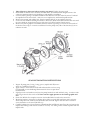
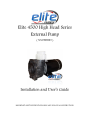
Elite 4500 High Head Series External Pump ( 5000EHH85 ) Installation and User’s Guide IMPORTANT SAFETY INSTRUCTIONS, READ AND FOLLOW ALL INSTRUCTIONS. SAVE THESE INSTRUCTIONS **NEVER RUN PUMP DRY!! NEVER EXCEED 25psi INTERNAL CASE PRESSURE!! ***THIS PUMP IS ONLY TO BE USED AS AN EXTERNAL “OUT-OF-POND” PUMP. NEVER ALLOW PUMP TO BECOME SUBMERGED!! We congratulate you on your choice of the ELITE PUMPS, INC. centrifugal pump. ALL OF OUR PUMPS CAN BE "VALVED BACK" AS LONG AS IT’S DONE ON THE DISCHARGE LINE. IT WILL NOT ONLY REDUCE THE FLOW, IT WILL LOWER THE WATT USEAGE AND EXTEND THE LIFE OF THE MOTOR AND THE SEAL! INSTALLATION Please read carefully! When properly installed, your new pump will provide dependable, trouble-free service. Do not submerse the unit in water - it is not a submersible pump. Do not allow the pump to become submerged or otherwise get wet. Locate the pump as near the source to be pumped as possible. A flooded suction is preferred. The pump is not self-priming. Therefore, if the fluid level is below the pump, a swing type check valve or a foot valve must be installed below water level. The pump and inlet line must be primed prior to start up. Do not run pump dry! Mount the motor base to a secure, immobile foundation preferably one that will dampen vibration. Use only plastic fittings on both the inlet and discharge ports. Seal the inlet & discharge fittings with Teflon pipe dope. These fittings should be self-supported and in neutral alignment with each port (i.e.,Fittings must not be forced into port alignment which may cause premature line failure or damage to the pump volute). Never restrict the inlet! Keep both inlet line as free of elbows and valves as possible. Always use pipe of adequate diameter. This will reduce friction losses and maximize output. Never use an inlet line of smaller diameter than the discharge line. Minimize the suction lift. NOTE: THE PUMP MOTOR IS DESIGNED FOR 115 VAC 60HZ POWER ONLY! WARNING: SHUT OFF ELECTRICAL POWER BEFORE INSTALLATION AND / OR SERVICING THIS PUMP! Carefully, examine the power cord before use. Do not use this power cord if there is any visible damage. Do not use this power cord in water or if the motor or electrical receptacle is in contact with any standing water! This power cord should only be plugged into a properly installed 115 VAC GFI receptacle! ALWAYS TEST CYCLE A GFI RECEPTACLE TO DETERMINE ITS CONDITION BEFORE USE! DISSASEMBLY 1. Shut off power to the motor before servicing any pump! Unplug the power cord. 2. Disassemble the bracket-motor assembly from the volute - six P-Bolts and six flanged lock nuts. The volute may remain attached to the plumbing to help simplify re-installation. 3. Lock the shaft by placing a screwdriver blade into the shaft slot at the fan end of the motor. Unthread the impeller from the motor shaft - Take care not to misplace the small metal impeller washer. 4. Remove the ceramic, with rubber boot, from the impeller hub (if you are replacing the seal). 5. Loosen the four M-Bolts attaching the bracket to the motor. Rotate the bracket counter-clock-wise until the screw heads are located in the large key hole slots. Lift off the bracket from the motor. 6. Remove the carbon-graphite seal assembly from the bracket by pressing it out from the motor-side of the bracket. Do not pry it out with a screwdriver from the pump cavity-side of the bracket (if you are replacing the seal)! SEAL INSTALLATION INSTRUCTIONS 1. Inspect all pump parts (O-ring, O-ring groove, impeller hub ID, motor shaft, etc.) and dean if necessary. 2. Apply sealant to the bracket bore ID wall and around the seal case using Gasgacinch® or a non-hardening Silicon material. Never use petroleum based materials. 3. Lightly press the seal member evenly into the pump bracket bore until uniformly snug. A ratchet socket that is larger than the face can be used. Never touch or apply pressure to the carbon graphite seal face. 4. Screw four M-Bolts five complete turns into the threaded holes located on the motor face. 5. Mount the bracket to the motor by aligning the key holes over each bolt head, then rotate cock-wise which will position the small key hole slot under each bolt head. Tighten each bolt with a wrench to secure the bracket to the motor (08-25 Ib. in.). 6. Carefully, lubricate the seal seat elastomer OD and impeller hub ID with water. Press the seal seat into the impeller hub making certain that the ceramic is in evenly - the sealing surface should be parallel with the impeller hub. 7. Apply clean water to the carbon-graphite and seal seat sealing surfaces. Do not use silicon lubricants or grease! 8. Lock the shaft by placing a screwdriver blade into the shaft slot at the fan end of the motor. Thread the impeller onto the motor shaft (Insure that the small impeller washer is in place on the impeller). Thread until the washer securely contacts the shaft shoulder. Be careful not to cross-thread the impeller. 9. Seat the large O-ring into the bracket O-ring groove. 10. Assemble the volute onto the bracket with six P-Bolts (10-24 x 2 3/4" carriage bolts) and six flanged lock nuts. Tighten in a cross pattern (30 Ib. in.). 11. Install the drain plug and O-rinq, into the volute drain hole. 12. Before operating, allow a proper cure time for the sealant used in steps 2 and 3. MAINTENANCE Lubrication Motor - Permanently Lubricated ball bearings - no service required. Rotary Seal - Requires no lubrication after assembly. The pump must be drained and the inside flushed if pump is to be stored for more than 3 months. Salt build up on seal will cause abrasion if left to dry. TROUBLESHOOTING AID Motor Just Hums Or Will Not Rotate Occasionally the seals on a newer pump are tight and they keep the pump from turning over. The motor hums but the impeller will not turn. There is an easy fix. Locate the flat-headed shaft screw at the rear of the motor, in the center. With the pump turned off, insert a flat-headed screwdriver into the screw and (while the pump is plugged in) give the screw-driver a clockwise twist. This should start a sticky pump. Once the seals are broken-in this should no longer be a problem. Pump is Noisy There are five principal causes of excessive noise: The fan is rubbing up against the fan cover. Simply remove the fan cover and run the pump. If noise ceases then reinstall fan cover allowing more clearance. A restriction on the intake line such as an elbow near the intake port or an intake line that is narrower than the discharge lines causes cavitation as well as pipe vibration. Test by restricting the discharge line and if noise lessens then intake restriction is the cause. Bearing noise. Please operate the pump continuously for 48 hours to allow bearing grease to properly disperse. If the noise persists then please follow the instructions on the enclosed warranty card. Placing the pump on a wood or metal. Use padding to eliminate resonance noise. There is a rubber washer (slinger) located on the shaft between the motor and the pump head. The slinger can move away from the middle and rub causing a squealing sound. Simply slide it back to the middle of the shaft.