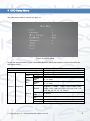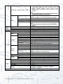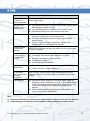
1
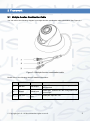
APOHDSDI-EYE 1080P HD-SDI ANALOGUE CAMERA User’s Manual V1.0 11 / 2013 i Welcome Thank you for purchasing our 1080P HD-SDI ANALOGUE CAMERA. This user’s manual is designed to be a reference tool for the installation and operation of your system. Here you can find information about the corresponding analogue camera’s features and functions, as well as a detailed installation method. Before installation and operation please read the following safeguards and warnings carefully! ii Important Safeguards and Warnings 1.Electrical safety All installation and operation here should conform to your local electrical safety codes. The power supply shall conform to the requirement in the SELV (Safety Extra Low Voltage) and must make sure that the limited power source is rated 12V DC. Please note: Do not connect two power supplying sources to the device at the same time; it may result in device damage! We assume no liability or responsibility for all the fires or electrical shock caused by improper handling or installation. We are not liable for any problems caused by unauthorized modification or attempted repair. 2.Transportation Security Please ensure that the product does not endure heavy stresses, violent vibration or contact with water during transportation, storage and installation. Please use the original packing material (or the material of the same quality) if you need to return it to vendor. 3.Installation Do not apply power to the product before completing installation. Do not put object(s) on the product. Please install a proper power cut-off device during the installation connection. 4.Qualified engineers needed All the examination and repair work should be done by the qualified service engineers. We are not liable for any problems caused by unauthorised modifications or attempted repair. 5. Environment This product should be installed in a cool, dry place away from direct sunlight, inflammable, explosive substances and etc. Please keep it away from environments that contain electromagnetic radiation or objects that produce it. Please keep sound ventilation around the device at all times. Do not allow the water and other liquid to penetrate into the device if casing has been compromised. This series product complies with the IP66 standard specified in the Degrees of Protection Provided by Enclosure. Ensure lightning surge protection is in place to make sure you fully protect camera circuitry from electrical overload. iii Please make sure the CCD (CMOS) component is away from the radiation of the laser beam device. Otherwise it may result in CCD (CMOS) optical component damage. It is recommended that the grounding studs of the product should be grounded, so to further enhance the reliability of the camera. 6. Daily Maintenance Please shut down the device and then unplug the power cable before you begin any maintenance work. Do not touch the CCD (CMOS) optic component. Please use an air jet to clean the dust off the lens surface. You can use the dry cloth with some alcohol or mild detergent to clear if necessary. When the camera is not in use please put the dustproof cap to protect the CCD (CMOS) component. Do not use volatile solvent such as the benzene, paint thinner or detergent with the ability to abrade surfaces. It may result in lens damage or adversely affect the device’s performance. 7. Accessories Always use all the accessories recommended by manufacturer. Before installation, please open the package and check that all the components are included. Contact your local retailer/vendor ASAP if something is missing. 8. Box Contents: Accessory Name Amount Camera Unit 1 User’s Manual 1 Installation Accessories Bag 1 CD 1 iv Table of Contents 1 General Introduction ...................................................................................................... 1 1.1 Overview ........................................................................................................... 1 1.2 Features ............................................................................................................ 1 1.3 Specifications .................................................................................................... 2 1.3.1 Performance ............................................................................................... 2 2 3 Framework..................................................................................................................... 3 2.1 Multiple-function Combination Cable................................................................. 3 2.2 Dimension ......................................................................................................... 4 Installation ..................................................................................................................... 5 3.1 Device Installation ............................................................................................. 5 4 OSD Setup Menu .......................................................................................................... 8 5 FAQ ............................................................................................................................. 10 v 1 General Introduction 1.1 Overview This type of camera conforms to the HD-SDI specifications. It supports high speed video signal, which means there is almost no delay in the transmission. The HD-SDI interface uses the coaxial cable to transmit video signals and uses the BNC port as the cable standard. The main benefit to this camera is its ability to record in 1080P HD definition, providing excellent quality video imagery to monitor. It also uses DC 12V for a power supply and you can use an inbuilt OSD button function to adjust internal camera settings. 1.2 Features Data Transmission Coaxial cable. Use the BNC port as the cable standard. Peripheral Equipment Support peripheral equipment connections via the RS485 port. Supports various peripheral device control protocols. . Power External power adapter. Supports a DC 12V power supply. Day/Night mode auto switch (ICR switch.) Supports OSD button function. Supports 1080P@25fps, 1080P@30fps, 720P@25fps, 720P@30fps, 720P@50fps, 720P@60fps. Supports WDR (Wide Dynamic Range). Supports anti-flicker. Supports HLC (Highlight Compensation). Backlight compensation: auto screen split to allow backlight compensation to adjust the brightness. Assistant Function © Copyright Qvis ®. All documentation rights reserved. 1 1.3 Specifications 1.3.1 Performance Please refer to the following sheet for digital camera performance specification: Model Parameter APOHDSDI-EYE System Video Parameters Main Processor High performance processor Image Sensor 1/3-inch CMOS Pixel 1920(H)*1080(V) Day/Night Gain Control White Balance Support day/night mode switch and IR-CUT at the same time. Fixed/Auto Manual/Auto/Day/Night Manual/Auto PAL: It ranges from 1/3 to 1/10000. NTSC: It ranges from 1/4 to 1/10000. Exposure Video Rate Frame Conform to the SDI specifications SMPT274/292 protocol Video Bit Rate PAL:1920*1080@25fps, 1280*720@25 fps, 1280*720@50 fps; NTSC:1920*1080@30fps, 1280*720@30 fps, 1280*720@60 fps Mirror Support mirror and flip Aux Function Image Video Information Lens Interface Support WDR, HLC, BLC, anti-flicker, low motion blur, low noise, 3D NR, motion detect, privacy mask Support parameter setup such as brightness, contrast. OSD menu M12 lens, 6mm (3.6mm optional) AUX Interface General Parameters Video Output 1-channel HD-SDI output RS485 Port May set image and OSD. Power Power Consumption IR Protective Level Working Temperature Working Humidify Dimensions (Unit: mm) Weight Installation Support DC 12V power Max: 5W 20m IP66 -10°C~+60°C ≤95% Φ 113×86 280g (without packaging) Wall-mount, ceiling © Copyright Qvis ®. All documentation rights reserved. 2 2 Framework 2.1 Multiple-function Combination Cable You can refer to the following diagram for multiple-function combination cable information. See Figure 2-1. Figure 2-1 Multiple-function combination cable Please refer to the following sheet for detailed information: SN Port Name Function Note 1 HD-SDI SDI output Sends SDI video stream conforming to the HDSDI standard. 2 RS485 RS485 port RS485 port. Controls the 485 configuration tool to set image. 3 DC 12V Power port Power port. Input DC 12V. input © Copyright Qvis ®. All documentation rights reserved. 3 2.2 Dimension Please refer to the following two figures for dimension information. The units are in mm. See Figure 2-2 and Figure 2-3. Figure 2-2 Dimension illustration 1 Figure 2-3 Dimension illustration 2 © Copyright Qvis ®. All documentation rights reserved. 4 3 Installation IMPORTANT: Before the installation, please make sure the installation surface can sustain at least 3X weight of the bracket and the camera. 3.1 Device Installation Please follow the steps listed below to install the device. Please refer to Figure 3-1 for reference. STEP 1: Turn the decoration ring clockwise to remove it from the snap joints. STEP 2: Please take the installation position map, in the accessories bag, and then paste it on to the ceiling or the wall according to your monitor area requirements. Draw and then drill three plastic expansion bolts holes in the installation surface and then insert three expansion bolts in the holes. Secure these three bolts firmly. Please draw the cable out from the cable exit when you install the device. STEP 3: Adjust the device installation pedestal to the proper position and then line up the three screw holes in the device pedestal to the three plastic expansion bolt holes in the installation position. Put the three self-tapping screws in the three plastic expansion bolts firmly. Loosen the M3X8 cross recessed pan head slot screw, of the pedestal, to unfasten the preforming (do not completely remove, just loosen). Adjust the lens to the proper monitor angle and then use the original preforming to turn the M3X8 cross recessed pan head slot screw back tightly. STEP4: Line up the three spigots of the decoration ring to the jags, from the bottom to the top and then turn clockwise until you hear the click sound. The installation is now complete. Figure 3-1 Device installation illustration 1 Important Please pay attention to the dome camera’s lens direction when you are installing. Please refer to the following figure for detailed information. See Figure 3-2. © Copyright Qvis ®. All documentation rights reserved. 5 Figure 3-2 Device installation illustration 2 Note This series product supports two cable exits. One is from the bottom and the other is from the side. Please refer to the following figure for cable exit from the side information. Figure 3-3 Device installation illustration 3 Please earth the GND port of the device to enhance the device reliability. The GND port is near the cable exit port on the rear of the dome. The GND uses the M2X5 pan screw. © Copyright Qvis ®. All documentation rights reserved. 6 Figure 3-4 Device installation illustration 4 © Copyright Qvis ®. All documentation rights reserved. 7 4 OSD Setup Menu The OSD setup interface is shown in Figure 4-1. Figure 4-1 OSD setup Please see the table below for more information about the options and modes to choose from within the OSD setup menus: Parameter Lens Auto Low noise Low Motion Blur Exposure Exposure Gain Max Gain Min Shutter Max Shutter Min Shutter Manual Shutter Max Shutter Min Gain Max Gain Min Note Mode: manual 0~ 100 0~ 100 P:0~ 40ms N:0~ 33ms P:0~ 40ms N:0~ 33ms 1/100000,1、10000, 1/4000, 1/2000, 1/1000, 1/500, 1/250, 1/120, 1/100, 1/60, 1/50, 1/30, 1/25, 1/15, 1/12, 1/10, 1/8, 1/6, 1/5, 1/4, 1/3, custom 0~ 300ms 0~ 300ms 0~ 100 0~ 100 © Copyright Qvis ®. All documentation rights reserved. 8 50HZ: 1/10000, 1/4000, 1/2000, 1/1000, 1/500, 1/250, 1/100, 1/50, 1/25, 1/12, 1/10, 1/6, 1/5, 1/4, 1/3 60HZ: 1/10000, 1/4000, 1/2000, 1/1000, 1/500, 1/250, 1/120, 1/60, 1/30, 1/15, 1/12, 1/8, 1/6, 1/4, custom Note: 50HZ and 60HZ modes have different exposure levels without low motion blur or low noise. BLC/WDR/HLC Note: You can enable only one mode at once. 0 means off. On, off 0~ 100 0~ 100 Note: Only auto exposure and outdoor anti-flicker have this function. Auto/Manual/Day/Night 0~ 100 0~ 100 Auto/BW/color Input up to 22 characters. On, off On, off On, off 0 ~3 On, off 0 ~ 100 0 ~ 100 Position, size Note: Adjust position and size via arrow key. Area 30, display off, sensitivity 50 On, off 0~7 On, off Position, size Note: Adjust position and size via arrow key. Display off English 1~ 254 115200, 38400, 9600, 2400 Click on Apply when you modified setup. 0~ 100 0~ 100 0~ 100 0~ 100 0~ 100 Anti-flicker(outdoor, 50HZ, 60HZ) BLC BLC BLC WDR HLC White Balance White Balance Blue Red Day&Night Camera Name Mirror Mirror Flip Motion Area Sel Area State Sensitivity Motion Threshold Area Setup Advanced Privacy Mask Default Privacy Mask Area Sel Area State Area Setup Default Language COM Setup Image 3DNR Sharpness Brightness Contrast Saturation Video Default Address Baudrate Apply 1080P@25, 1080P@30, 720P@25, 720P@30, 720P@50, 720P@60 Except video and language, restore all default. © Copyright Qvis ®. All documentation rights reserved. 9 5 FAQ Bug Solution / Reason I cannot boot up the device or operate it properly. Please click the RESET button for at least five seconds to restore factory default setup. The water has leaked into the camera casing The unauthorised front or rear cap removal many result in water leaking into the camera housing. The glass front cap has sustained a heavy knock or strike. The waterproof plug of the rear cap has come loose. IR video is poor. The Incorrect supply power has been used. The IR light cannot provide illumination up to its maximum level. The object being monitored/focused upon is out of the IR distance range. IR-CUT does not turn to the night mode. The front end photosensitive chip cannot sense the IR light. I cannot upgrade the device via network. I cannot login to the client-end or the WEB online service. When network upgrade operation has failed, you can use port 3800 to continue upgrade. The Active X control is blocked. The display card version needs to be DX8.1 or higher. Network connection error has occurred. Invalid network setup. Invalid user name or password. I cannot play the download file. To guarantee setup update once you have completed it Power adapter There is no video player installed. There is no DX8.1 or higher installed. After you have modified setup, please reboot the device via the software to make sure the setup has been updated to the storage medium. The general power adapter can only work reliably within the temperature range of between 0℃ to 40 ℃. If the power supply is being operated outside this temperature range then this may result in an unstable power supply being provided to the camera. Please replace with an industrial-grade power adapter if you are using it in a harsh environment. Note This user’s manual is for reference only. Slight differences may be found in user interface. All the designs and software here are subject to change without prior written notice. © Copyright Qvis ®. All documentation rights reserved. 10 For more information about our IP Cameras and other available cameras, NVRs & accessories, please visit our website: www.adata.co.uk Alternatively scan this QR code with your smart phone to be directed instantly to our website: © Copyright Qvis ®. All documentation rights reserved. 11