1
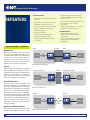
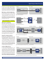
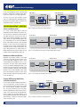
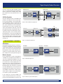
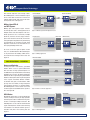
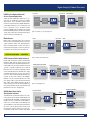
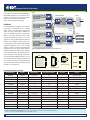
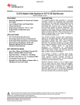
Integrated DeviceTechnology
DeviceTechnology
Integrated
Signal Integrity Products
POWER MANAGEMENT | ANALOG & RF | INTERFACE & CONNECTIVITY | CLOCKS & TIMING | MEMORY & LOGIC | TOUCH & USER INTERFACE | VIDEO & DISPLAY | AUDIO
TARGET APPLICATIONS
Repeaters:
PCI Express® Gen 2 Applications
With the increase of signal speeds in the computing, storage and communications applications, system designers face greater signal integrity challenges. The Signal Integrity Product (SIP) portfolio from Integrated Device Technology provides signal conditioning devices
• Blade servers
for popular multi-gigabit per second IO protocols delivering signal quality over extended • Storage systems
distances while offering simplified design by alleviating board layout constraints.
• Cabled PCIe devices
• Notebooks & Docking stations
• Mux, Demux, and Switch
USB 3.0 Applications
• Workstations & Desktops
• Notebooks & Docking stations
• Peripheral USB devices
SAS/SATA Applications
• Servers & Workstations
• Notebooks & Docking stations
Figure 1: Typical Signal Deterioration Over Long Channels
• External SATA storage drives
Signal Integrity Challenge
• SAS port expanders
High speed signals can deteriorate to unacceptable levels by the time they reach end receivers,
due to transmitter, receiver, and channel characteristics (see figure above).
Serial RapidIO® Applications
• ATCA blades
• Wireless systems
• Military VITA-41 & VPX systems
XAUI Applications
• Routers & Switches
• ATCA blades
• PON access systems
• Blade servers
Other Applications
• Common public radio interface (CPRI)
• Open base station architecure (OBSAI)
• Infiniband
Retimers
PCI Express® Gen 3 Applications
IDT Repeaters and Retimers
Resolve Signal Integrity Challenges
IDT’s Family of Repeaters and Retimers is specifically designed to resolve the issue shown in the
above figure and to ensure minimized jitter and
maximized eye opening at the target receiver by
compensating for cable and PCB trace attenuation and ISI jitter. This is accomplished by boosting the transmitted signal, by equalizing the received signal, or by doing both when either option
by itself is not sufficient due to channel length or
due to discontinuities generated by vias and connectors. In addition, IDT Retimers minimize random jitter, further increasing signal quality.
• Computing
• Storage
IDT Repeaters
• Communications
The IDT SIP family of repeater devices include
support for: 5Gbps PCI Express® (PCIe) Gen2,
USB 3.0, 6Gbps SAS/SATA; 6.25Gbps Serial
RapidIO® 2.1, and other standards for computing,
storage and communications applications.
• Consumer electronics
For help or more information:
Hotline: (408) 284 8208
email: [email protected]
IDT | THE ANALOG + DIGITAL COMPANY
SIP devices incorporate advanced receive equalization and transmit de-emphasis capabilities, as
well as diagnostic features that help IDT customers achieve a simplified design with faster timeto-market. Specifically, the devices drive long
on-board traces, backplane traces and cables to
external devices to ensure optimum system performance. In addition, they include loss of signal
(LOS) detection and individual channel loopback
diagnostic capabilities as well as 2:1 mux/demux
functions. Devices support 2, 4, or 8 differential
channels, configurable via I2C, control pins, or
EEPROM. The devices offer power-saving modes
for the lowest possible power consumption.
IDT Retimers
The IDT Retimer devices are the industry’s first
signal-conditioning parts fully compliant with
the PCIe 3.0 specification. They are compliant to
the PCIe Automatic Link Equalization procedure,
easing system design and enhancing reliability with any PCIe-compliant expansion card or
host bus adapter. IDT Retimers are designed to
improve signal integrity and to more than double
maximum PCB trace and cable lengths. These
devices minimize both random and deterministic
jitter from the input signal before transmitting it
out to target devices.
IDT Repeaters and Retimers are ideal for solving signal integrity problems in blade servers,
enterprise storage, communication systems, and
cloud computing.
SIGNAL INTEGRITY PRODUCT FAMILY OVERVIEW 1
Integrated Device Technology
REPEATERS
REPEATER FEATURES
•Supports automatic download of configuration
from external EEPROM with a single or multiple
repeaters on I2C bus
•Compensates for cable and PCB trace attenuation
and ISI jitter
•Power minimization in active and shutdown modes
•Programmable receiver equalization up to 30db
•No external bias resistors or reference
clocks required
•Programmable de-emphasis up to -8.5dB
•Recovers data stream even when the differential
signal eye is completely closed due to trace
attenuation and ISI jitter
•Channel mux mode, demux mode, 1 to 2 channels
multicast, and Z-switch function mode
REPEATER BENEFITS
•Full PCIe protocol support
•Extends maximum cable length to over
10 meters and trace length over 65 inches in
PCIe applications
•SAS/SATA, Out of Board (OOB) Support
•Configurable via external pins, while
extended programming ranges are available
via I2C interface
PCIe APPLICATIONS — REPEATERS
Blade
•Speeds up system design time by allowing
usage of longer trace and cable lengths
•Minimizes BER
Back Plane
Blade
Blade Servers
Blade servers inherently require the use of long
interconnects and multiple connectors to transfer signals between blades. IDT PCIe Repeaters
can be used to transmit boosted signals into
backplanes and to recover from long trace-related and connector-related signal attenuations
and jitter at the receiving end. See Figure 2.
Chipset
PCIe
(Trace)
Repeater
Repeater
PCIe
(Trace)
Chipset
x16 PCIe
(Trace)
Figure 2: Blade Server Application
Storage
Similar to blade server applications, Storage Area
Networks (SAN) face a challenge of transferring
reliable PCIe signals between redundant storage
processors. IDT PCIe Repeaters can boost transmitted signals and restore noisy and attenuated
signals at the receiving end. See Figure 3.
Storage Processor Card
Chipset
PCIe
(Trace)
Mid Plane
Repeater
PCIe
(Trace)
Storage Processor Card
Repeater
PCIe
(Trace)
Chipset
PCIe
(Trace)
Chipset
Cabled PCIe Systems
There are various system applications using
cables to transmit PCIe signals between chassis
(see Figure 4). Networking and storage equipment, medical instrumentation, data acquisition
systems such as scopes and protocol analyzers,
and peripheral devices are just a few examples
of PCIe cabled systems. IDT Repeaters permit the
use of less expensive and longer cables, allowing for significant savings and improving distance
constraints. Expensive PCIe cables can be replaced with less expensive ones for a significant
savings. See Figure 4.
Figure 3: Storage Application
System B
System A
Chipset
PCIe
(Trace)
PCIe
Repeater
(Cable)
Repeater
Notebooks and Docking Stations
PCIe connectors available in docking stations
need to pass the compliance test. This is a chal2 SIGNAL INTEGRITY PRODUCT FAMILY OVERVIEW
Figure 4: Cabled PCIe Application
IDT | THE ANALOG + DIGITAL COMPANY | www.IDT.com
Signal Integrity Product Overview
Notebook
Docking Station
PCIe
(Trace)
Chipset
PCIe
(Trace)
PCIe Connector
lenging test, since a signal’s quality degrades as
it passes from the chipset inside the notebook,
through traces and connectors. IDT Repeaters
can be used at the PCIe connector inside the
docking station to resolve this issue. See Figure 5.
Repeater
Mux, Demux, and Switch Applications
IDT PCIe Repeaters permit a variety of muxing
(2 links to 1 link), demuxing (1 link to 2 links), and
switching configurations (2 links to 2 links) supporting long traces and cables (see Figure 6). Detailed information on all these configurations can
be found in the “Channel muxing” sections of IDT
PCIe Repeater data sheets.
USB 3.0 APPLICATIONS — REPEATERS
Figure 5: Notebook Application
PCIe
Host
Repeater
PCIe
Host
End
Point
PCIe
EQ
Workstations and Desktops
Workstations and desktops, due to their size, inherently require the use of long interconnects to
transfer signals from internal boards to front and
back panel USB ports. Each USB 3.0 port needs
to pass the compliance test. This can be a challenging test, since a signal’s quality degrades as
it passes from the USB 3.0 controller, through
traces, cables, and connectors, to the USB ports.
To resolve this issue, IDT USB Repeaters can be
used at both back panel and front panel USB 3.0
ports to restore the signals at the ports and prevent compliance test issues. See Figure 7.
Figure 6: Mux / Demux Application
Front Panel
Back Panel
Workstation or Desktop
Front Panel Card
USB 3.0 Port
ot
USB 3.00 Port
Internal
Cable
Repeater
USB
B 33.0
.00 ((Trace)
Tra
racce)
USB 3.0
(Trace)
USB
Controller
USB 3.0
(Trace)
Repeater
Connector
Figure 7: Workstation and Desktop Application
Notebooks and Docking Stations
Peripheral USB 3.0 Devices
In cases where peripheral USB devices, such
as hard disk drives, solid state drives, printers,
and wireless routers, are placed at a significant
distance from the USB host system (desktop,
notebook, workstation, etc.), the signals transmitted across long cables might be degraded to the
point of being unrecoverable at the receiving end.
With signal pre-conditioning, IDT USB Repeaters
reduce the effect of degradation and enable the
www.IDT.com | THE ANALOG + DIGITAL COMPANY | IDT
Notebook
USB 3.0
(Trace)
USB 3.0
(Trace)
Repeater
USB 3.0 Port
Chipset
Docking Station
Connector
Figure 8: Notebook Application with Chipset Containing USB 3.0 Controller
Notebook
Chipset
Docking Station
USB 3.0
Controller
USB 3.0
(Trace)
USB 3.0
(Trace)
Repeater
USB 3.0 Port
Docking stations using USB 3.0 connectors need
to pass USB compliance, which is measured at
a USB 3.0 port. This is a challenging test, since
a signal’s quality degrades as it passes from the
chip set (Figure 8) or USB 3.0 controller (Figure
9) inside the notebook, through traces and connector on its path, to a USB 3.0 port. IDT USB Repeaters can be used at the USB 3.0 port inside
the docking station to boost the signal at the port,
thereby resolving the degradation issue.
Connector
Figure 9: Notebook Application with USB 3.0 Controller Not Included in ChipsetController
SIGNAL INTEGRITY PRODUCT FAMILY OVERVIEW 3
Integrated Device Technology
use of very long USB 3.0 cables. With IDT USB
Repeaters, inexpensive and lower quality cables
can also be used for cost-sensitive applications.
To ensure successful signal reception at both
ends, it is recommended that IDT USB Repeaters
be placed near the USB 3.0 ports inside the host
and peripheral device. See figure 10.
USB 3.0 Peripheral
USB 3.0 Host
USB 3.0 Port
Chipset
USB 3.0 Port
USB 3.0
Cable
Repeater
Target
USB 3.0
Device
Repeater
USB
B 3.
33.00 ((Trace)
Trace))
USB
B 3.
33.00 ((Trace)
Trace))
SAS, SATA APPLICATIONS — REPEATERS
Servers and Workstations
In a server, storage drives (HDD or SSD) are
plugged directly into a midplane card, which connects to the main system board containing CPUs
and HBAs. During the transmission of SAS or
SATA signals between CPUs/HBAs and storage
drives, signals are significantly degraded as they
pass through long traces on system and midplane
boards and multiple connectors. IDT SAS/SATA
Repeaters can be used to ensure that differential
eye opening at the receiver exceeds 6Gbps SAS
and SATA receiver standard specifications. The
figures below depict the use of IDT repeaters in
6Gbps SATA-based data transfers (Figure 11) and
in 6Gbps SAS-based applications (Figure 12).
Figure 10: Application with Peripheral USB 3.0 Devices
Chipset
with SATA
Controller
Stor
Storage
Mid
plane Board
Midplane
System Board
SAS
(Trace)
S
SSD/HDD
S
SSD/HDD
S
SSD/HDD
S
SSD/HDD
S
SSD/HDD
S-RIO
S
SSD/HDD
(Trace)
S
SSD/HDD
S
SSD/HDD
Repeater
C
onnnec
on
ecttor
Connector
Figure 11: Server Application with Chipset Containing 6Gbps SATA Controller
Notebooks and Docking Stations
External SATA Storage Hard Drives
and Solid State Drives
In cases where peripheral SATA storage devices,
such as hard disk drives or solid state drives, are
placed a significant distance away from the SATA
host system (desktop, notebook, workstation,
etc.), the signal transmitted across long cables
might be degraded to the point of being unrecoverable at the receiving end. IDT SAS/SATA Repeaters resolve this issue and enable the use of
very long 6Gbps SAS/SATA cables. With IDT SAS/
SATA Repeaters, inexpensive and lower quality
cables can also be used.
4 SIGNAL INTEGRITY PRODUCT FAMILY OVERVIEW
System Board
Chipset
Midplane Board
SAS
(Trace)
SAS
Controller
Repeater
Storage
SAS
(Trace)
SSD/HDD
SSD/HDD
SSD/HDD
SSD/HDD
SSD/HDD
S-RIO
SSD/HDD
(Trace)
SSD/HDD
SSD/HDD
Connector
Figure 12: Server Application with 6Gbps SAS Controller
eSATA Port
Notebook
Docking Station
Repeater
Chipset
SATA
(Trace)
Repeater
eSATA Port
Notebooks and Docking Stations using eSATA
connectors for peripheral storage devices need
to pass SAS/SATA compliance, which is measured at 6Gbps SAS or SATA port. This is a challenging test, since the signal’s quality degrades
as it passes from the SATA/eSATA adapter card,
through traces and connectors on its path, before
reaching the 6Gbps eSATA port. IDT SAS/SATA
Repeaters can be used at the 6Gbps SAS or SATA
port inside the docking station to restore signal
quality at the port and prevent compliance failure
issues. See Figure 13.
Connector
Figure 13: Notebook and Docking Station Application
IDT | THE ANALOG + DIGITAL COMPANY | www.IDT.com
Signal Integrity Product Overview
To ensure successful signal reception at both
ends, it is recommended that IDT SAS/SATA Repeaters be placed near the 6Gbps SAS or SATA
ports inside the host and peripheral device. See
Figure 14.
eS
ot
eSATA Port
Chipset
SAS Port Expanders
One of the important features of the 6Gbps SAS
protocol is its ability to increase storage capacity via SAS Port Expanders. The standard allows
up to 255 expanders, which can translate to Petabytes of total storage within a single system. The
host system communicates with the expanders
through cables that can be up to 10 meters long.
To pass SAS compliance, both host system and
port expander SAS ports need to deliver high signal quality so that the transmitted signals, attenuated by long cables, can be correctly received.
IDT SAS Repeaters can be used at the 6Gbps SAS
port inside the host system and port expanders to
boost transmitted signals, to restore the received
signals at the port, and assure reliable operation.
See Figure 15.
S-RIO APPLICATIONS — REPEATERS
SATA storage
Notebook or PC
SATA/
eSATA
adapter
card
Repeater
S
ot
eSATA
Port
eSATA
Cable
HDD,
SSD
Repeater
R
epeater
Repeater
(USB 3.0 Trace)
Connector
Figure 14: External SATA Storage Application
System Board
Chipset
Midplane Board
SAS
Controller
SAS
(cable)
Expander unit
SAS
(cable)
Expander unit
Storage
SSD/HDD
SSD/HDD
SSD/HDD
SSD/HDD
Repeater
StorageS-RIO
Port Expander
Repeater
Connector
SAS
cables
Port Expander
SSD/HDD
SSD/HDD
SSD/HDD
SSD/HDD
Repeater
Port
SAS
cables
Figure 15: Port Expanders Application
ATCA Blades
ATCA blades inherently require the use of long interconnects and multiple connectors to transfer
signals between blades. IDT Serial RapidIO Repeaters can be used to transmit boosted signals
into backplanes and to recover from long tracerelated and connector-related signal attenuations and jitter at the receiving end. See Figure 16.
ATCA Blade
Chipset
Back Plane
S-RIO
(Trace)
Repeater
S-RIO
(Trace)
ATCA Blade
Repeater
S-RIO
(Trace)
Chipset
Wireless Systems
Carrier grade wireless systems are designed for
scalability via (1) backplane-based modular designs or (2) a combination of midplane cards and
external expansion cards. In the first case, during
the transmission of Serial RapidIO packets between S-RIO cards, signals are significantly degraded as they pass through long trace lines on
backplane boards, two connectors, and several
vias. IDT S-RIO Repeaters can be used to ensure
that differential eye openings at the receiver exceed 6.25Gbps S-RIO receiver standard specifications. Figure 17 depicts the use of IDT repeaters in wireless systems with backplanes
In the second case, the main controller card
needs to communicate both with an internal expansion card through midplane card traces and
www.IDT.com | THE ANALOG + DIGITAL COMPANY | IDT
Figure 16: ATCA Blade Application
Baseband processing board
DSP
units
S-RIO
switch
Back Plane
Repeater
S-RIO
(Trace)
Baseband processing board
Repeater
S-RIO
switch
DSP
units
Figure 17: Wireless Systems with Backplanes
SIGNAL INTEGRITY PRODUCT FAMILY OVERVIEW 5
Integrated Device Technology
with external expansion cards through cables.
IDT S-RIO Repeaters can be used to boost signals
for trace and cable transmissions and to ensure
reliable communication with internal and external expansion cards. See Figure 18.
Expansion
p
Module
Control Module
Controller
Card
S-RIO
(Trace)
To ensure successful signal reception at both
ends, it is recommended that IDT S-RIO Repeaters be placed near the 6.25Gbps S-RIO connectors inside the host and target switch cards. See
Figure 19.
XAUI APPLICATIONS — REPEATERS
Routers and Switches
In enterprise routers and switches, specialized
modules within a chassis system communicate
with each other via high speed backplanes. As
the 10Gb Ethernet protocol becomes more widely
adopted in these systems, backplanes implement
XAUI connections required by the protocol. Both
modules and backplanes often require long board
traces. Signals transmitted between modules
accumulate noise, jitter, and attenuations while
passing from one module, through backplane
and backplane connectors, to another module.
IDT XAUI Repeaters can be used to ensure that
received signals exceed XAUI receiver specifications. See Figure 20.
ATCA Blades
ATCA blades make heavy use of inter-blade data
transfers, making it necessary for high speed differential signals to be transmitted over long interconnects and through multiple connectors. IDT
XAUI Repeaters can be used to transmit boosted
signals into backplanes and to recover from long
trace-related and connector-related signal attenuations and jitter at the receiving end. See
Figure 21.
6 SIGNAL INTEGRITY PRODUCT FAMILY OVERVIEW
Repeater
Back Plane
Switch Cards
S-RIO
(Trace)
Expansion
Signal
Processing
Card
Signal
Processing
Card
Military Open VITA-41
and VPX Systems
Military Open VPX Systems require transfers
of S-RIO packets from a S-RIO payload card to
multiple switch cards via backplanes. The transmitted signal must cross 2 connectors, multiple
board vias, and traces on host, target, and backplane cards. Due to this connection, the transmitted signal might be degraded to the point of being
unrecoverable at the receiving end. IDT S-RIO
Repeaters resolve this issue and enable the use
of very long 6.25Gbps S-RIO traces.
Repeater
S-RIO
Cable
Figure 18: Wireless Systems with Expansion Cards
Payload Card
PowerPC /
FPGA
S-RIO
(Trace)
Repeater
S-RIO
(Trace)
Repeater
S-RIO
(Trace)
S-RIO
Switch
and
Chipset
CPUs
Figure 19: Military Application
Backplane
Ethernet module
XAUI
(Trace)
Ethernet controller
Repeater
XAUI
(Trace)
Supervisor module
XAUI
(Trace)
Supervisory circuits
Repeater
XAUI
(Trace)
Security module
XAUI
(Trace)
Security Circuits
Repeater
Figure 20: Router or Switches Application
ATCA Blade
10GbE
MAC
Back Planee
XAUI
(Trace)
Repeater
XAUI
(Trace)
ATCA Blade
Repeater
XAUI
(Trace)
10GbE
Chipset
MAC
Figure 21: ATCA Application
IDT | THE ANALOG + DIGITAL COMPANY | www.IDT.com
Signal Integrity Product Overview
PON (Passive Optical Network)
Access System Application
Similar to ATCA applications, PON access systems face the challenge of transferring reliable
XAUI signals across backplane. XAUI signals
need to be transferred from a 10GbE (10Gbit Ethernet) MAC located on a line card through card
traces, connectors, and a backplane before
reaching a 10GbE switch included on the control
board. IDT XAUI Repeaters can boost transmitted
signals and restore noisy and attenuated signals
at the receiving end. See Figure 22.
Blade Servers
Blade servers inherently require the use of long
interconnects and multiple connectors to transfer
signals between blades. IDT XAUI Repeaters
boost transmitted signals, restore noisy and attenuated received signals, and ensure good signal quality at the receiving end. See Figure 23.
Line Card
Network
Processor
Back Planee
10GbE
MAC
Control Board
XAUI
(Trace)
Repeater
Repeater
10GbE
Switch
Figure 22: PON Access System Application
Blade
10GbE
MAC
Back Plane
XAUI
(Trace)
Repeater
XAUI
(Trace)
Blade
Repeater
XAUI
(Trace)
10GbE
Chipset
MAC
OTHER APPLICATIONS — REPEATERS
CPRI (Common Public Radio Interface)
Public radio transmission stations contain Radio
Equipment (RE) with RF front end circuits that
need to communicate with Radio Equipment Controllers (REC). The connection between these two
systems is typically established via an optical
CPRI link. There are different topologies linking
one or more REC with one or more RE units: single
or multiple point-to-point, ring, tree, and chain. In
each case, if the connection lengths between the
systems are less than 15 meters, IDT 6.25Gbps
Repeaters can be used to enable the use of low
cost copper cables in place of expensive optical
fiber cables. IDT 6.25Gbps Repeaters placed at
cable connectors ensure that received CPRI signals exceed minimum receiver specifications and
minimize bit error rates. See Figure 24.
OBSAI (Open Base Station
Architecture Initiative)
The OBSAI RP3 specification defines the interface between the baseband control module and
the Remote Radio Unit (RRU). A single Baseband
module can act as a hub to one or more RRUs. In
some cases, it is desirable to have RRUs placed
several kilometers away from the baseband module. In this scenario, optical cables must be used
to connect the systems. In other cases, main control modules reside within 15 meters from RRUs
www.IDT.com | THE ANALOG + DIGITAL COMPANY | IDT
Figure 23: Blade Server Application
Radio Equipment Control
Radio Equipment
CPRI
Control S-RIO
Module (Trace) Repeater (cable) Repeater
Radio Equipment
RRadio
M
Module
CPRI
S-RIO Radio
Repeater (cable) Repeater (Trace) Module
Figure 24: CPRI Application
Remote Radio Unit
Baseband Hub
Baseband
Control
module
OBSAI
(cable)
Repeater
RF Block
Remote Radio Unit
Repeater
OBSAI
(cable)
Repeater
RF Block
Port
Figure 25: OBSAI Application
SIGNAL INTEGRITY PRODUCT FAMILY OVERVIEW 7
Integrated Device Technology
and, similar to short-distance CPRI applications,
IDT 6.25Gbps Repeaters can be used in these applications to enable the use of low cost copper
cables in place of expensive optical fiber
cables. See Figure 25 (previous page).
Infiniband
In high-performance computing and enterprise
data centers, an Infiniband link is a preferred
choice with its high throughput, low latency,
quality of service, failover, and scalability features. The InfiniBand architecture specification
defines a connection between processor nodes
and high performance I/O nodes, such as storage devices. The specification allows wide area
networks, but Infiniband is mostly used as a local storage area network (SAN). In SAN topology,
Infiniband components such as links, channel
adaptors, switches, and routers typically transfer
Infiniband packets via copper cables. Because
Infiniband components might be several meters
away from one another, transmitted signals between components may degrade and become
unrecoverable. IDT 6.25Gbps Repeaters can be
used at Infiniband ports to boost transmitted signals and to restore noisy and attenuated signals
at the receiving end, thereby resolving this signal
integrity issue. See Figure 26.
Server
Infiniband
circuits
Infiniband Switch
Infinibandd
(Trace) Repeater
Server
Sw
Switch
C
Card
Repeater
Infiniband
circuits
Router
Ethernet
Repeater
Infinibandd
(Trace) Repeater
Infiniband
(cables)
Server
Infiniband
circuits
Infiniband Switch
Infinibandd
(Trace) Repeater
Server
Sw
Switch
CCard
Repeater
Infiniband
circuits
Storage
SSD/HDD
SSD/HDD
SSD/HDD
SSD/HDD
SSD/HDD
S-RIO
SSD/HDD
Repeater
Infinibandd
(Trace) Repeater
Figure 26: Infiniband Storage Area Network (SAN) Application
Actual Size
Package Types and Proportions
4mm
9mm
4mm
100 BGA
4mm
7.5mm
9mm
20-QFN
36-QFN
(0.5mm pad pitch)
36-QFN
100 BGA
20-QFN
(0.5mm pad pitch)
IDT REPEATER PRODUCT SELECTOR
IDT Part Number *
Protocol
Configurability**
Max Data Rate (Gbps)
Channels
Package
89HP0504P
PCIe Gen 2
Pins and I C
5.0
4
100-BGA, 36-QFN
89HP0504PB
PCIe Gen 2
Pins
5.0
4
36-QFN
89HP0508P
PCIe Gen 2
I2C
5.0
8
100-BGA
89HP0504U
USB 3.0
Pins
5.0
4
36-QFN
89HP0504UB
USB 3.0
IC
5.0
4
36-QFN
2
2
89HP0604S
SAS/SATA
Pins and I C
6.0
4
100-BGA, 36-QFN
89HP0604SB
SAS/SATA
Pins
6.0
4
36-QFN
89HP0608S
SAS/SATA
IC
6.0
8
100-BGA
89HP0604R
Serial RapidIO
Pins and I C
6.25
4
100-BGA
89HP0608R
Serial RapidIO
I2C
6.25
8
100-BGA
89HP0604X
XAUI
Pins and I C
6.25
4
100-BGA
2
2
2
2
2
89HP0608X
XAUI
IC
6.25
8
100-BGA
89HP0604Q
Multi
I2C
6.25
4
36-QFN
89HP0604QB
Multi
Pins
6.25
4
36-QFN
89HP0602Q
Multi
Pins
6.25
2
20-QFN
* Part ordering for variations: green or non green package, commercial or industrial range, and tape and reel / bulk. In addition, 100-BGA and 36-QFN package variations are
available for 89HP0504P and 89HP0604S parts. Please, refer to last page of datasheets for orderable part numbers
** Use I2C for access to the full extended set of configuration options
8 SIGNAL INTEGRITY PRODUCT FAMILY OVERVIEW
IDT | THE ANALOG + DIGITAL COMPANY | www.IDT.com
Signal Integrity Product Overview
RETIMER FEATURES
High Performance
•Minimizes random input jitter
•Minimizes deterministic ISI jitter
•Compensates for channel attenuations
•Tunable RX and TX performance and power
•Up to 8dB of transmit deemphasis
•Programmable multi-stage equalizer
•CTLE and 5 tap DFE
•Fast acquisition PLL for L0s exit
•On-chip SERDES eye scope
SerDes Power Savings
•Supports low swing operation
•Auto low power for unused lanes
PCIe Standards and Compatibility
•PCI Express Base Specification 3.0 compliant
•PCI Express Base Specification 2.1 compliant
Hot Plug Support
•Link Configurability
•Configurable to 1x8, 1x4, 1x1, 2x4, 2x1
•Automatic per port link width negotiation
•Per-lane SerDes configuration
– De-emphasis, equalization, drive
Clocking
•Standard 100 MHz PCIe reference clock
•SSCLK (Spread Spectrum) and non-SSCLK
•Writing new or initial image into
external EEPROM
•Expose internal global CSR space to
system controller
Reliability, Availability and Serviceability
•Physical layer error checking and accounting
•End-to-end data path parity protection
PCIe Applications — Retimers
IDT Retimer devices contain a mix of high performance and instrumentation features and include extensive configurability of RX and TX functions. These retimers fully support the automatic equalization
procedure, newly defined in the PCIe 3.0 specification. The parts are optimized for power consumption
and incorporate high performance features, such as multi-stage equalizer with CTLE and 5 tap DFE,
automatic handshake for RX equalization compliant with PCIe Express® 3.0, and fast acquisition PLLs
for L0 exits.
Test, debug, and optimization features make this part ideal for quick design turnaround time. For example, on-die eye scope with in-field diagnostics is provided for quick in-system optimization of eye
characteristics via multiple configuration registers. An evaluation board is also available and is accompanied by a user-friendly graphical user interface (GUI) software utility. The family of Retimers
also supports extensive configurability for every feature via an SMBus or I2C slave device. Additionally,
the configuration data can be downloaded from a serial-EEPROM. Multiple features are provided to
minimize power consumption, including Active State Power Management (ASPM) of each link as well
as half-swing SerDes mode and automatic power reduction on unused lanes. IDT Retimers, similar to
IDT PCIe Repeaters, are ideal for high performance enterprise applications including blade servers,
enterprise storage, communication systems, and cloud computing.
•Checksum Serial EEPROM content protected
Test and Debug
•Per link/lane error diagnostic registers
•All registers accessible from I2C or JTAG port
•SerDes test modes
•Several loopback modes
www.IDT.com | THE ANALOG + DIGITAL COMPANY | IDT
SIGNAL INTEGRITY PRODUCT FAMILY OVERVIEW 9
Integrated Device Technology
COLLATERAL DOCUMENTATION
89HP0504P 4-channel PCIe Gen2 Signal Repeater
89HP0504P Product Brief
89HP0504P Data Sheet
89HP0504P Device Errata (Revision ZB)
89HP0504P Device Errata (Revision ZA)
AN-728: IDT Signal Repeater - Managing Board designs
Across Silicon revisions “Q”, “ZA” and “ZB”
89EBP0504P (BGA) Evaluation Board
User Manual
89EBP0504P (BGA) Eval Board Schematics
(layered for online viewing)
89EBP0504P (BGA) Eval Board Schematics
(optimized for printing)
89EBP0504P (BGA) Eval Board Schematics Cadence Database
89EBP0504P (BGA) Eval Board OrCAD Schematics
89EBP0504P (QFN) Eval Board Schematics
(layered for online viewing)
89EBP0504P (QFN) Eval BoardSchematics
(optimized for printing)
89EBP0504P (QFN) Evaluation Board User Manual
89EBP0504P (QFN) Eval Board Schematics
(layered for online viewing)
89EBP0504P (QFN) Eval Board Schematics
(optimized for printing)
89EBP0504PB (QFN) Evaluation Board
User Manual
89HP0504PB 4-channel PCIe Gen2 Signal Repeater
89HP0504PB Product Brief
89HP0504PB Data Sheet
89HP0504PB Device Errata (Revision ZB)
89HP0508P 8-channel PCIe Gen2 Signal Repeater
89HP0508P Product Brief
89HP0508P Data Sheet
89HP0508P Device Errata (Revision ZB)
89HP0508P Device Errata (Revision ZA)
AN-728: IDT Signal Repeater - Managing Board designs
Across Silicon revisions “Q”, “ZA” and “ZB”
89EBP0508P Eval Board Schematics
(layered for online viewing)
89EBP0508P Eval Board Schematics (optimized for printing)
89EBP0508P Eval Board Schematics Cadence Database
89EBP0508P Eval Board Layout Database
89EBP0508P Evaluation Board User Manual
89EBP0508P Eval Board Schematics
(layered for online viewing)
89EBP0508P Eval Board Schematics (optimized for printing)
89EBP0508P Eval Board Schematics Cadence Database
89EBP0508P Eval Board OrCAD Schematics
89HP0504U 4-channel USB 3.0 Signal Repeater
89HP0504U Product Brief
89HP0504U Data Sheet
89HP0504U Device Errata (Revision ZB)
89HP0504U Device Errata (Revision ZA)
10 SIGNAL INTEGRITY PRODUCT FAMILY OVERVIEW
89EBP0504U Evaluation Board
User Manual
89EBP0504U Eval Board Schematics
(layered for online viewing)
89EBP0504U Eval Board Schematics (optimized for printing)
89HP0602Q 2-channel 6.25Gbps Signal repeater
89HP0602Q Product Brief
89HP0602Q Data Sheet
89HP0602Q Device Errata (Revision ZB)
89EBP0602Q SATA Evaluation Board
User Manual
89EBP0602Q-SATA Eval Board Schematics
(layered for online viewing)
89EBP0602Q-SATA Eval Board Schematics
(optimized for printing)
89HP0504UB 4-channel USB 3.0 Signal Repeater
89HP0504UB Product Brief
89HP0504UB Data Sheet
89HP0504UB Device Errata (Revision ZB)
89EBP0504UB Evaluation Board
User Manual
89EBP0504UB Eval Board Schematics
(layered for online viewing)
89EBP0504UB Eval Board Schematics (optimized for printing)
89EBP0602Q USB Evaluation Board
89EBP0602Q-USB Eval Board Schematics
(layered for online viewing)
89EBP0602Q-USB Eval Board Schematics
(optimized for printing)
EBP0602Q USB Evaluation Board User Manual
89HP0604S 4-channel SAS/SATA 6G Signal Repeater
89HP0604S Product Brief
89HP0604S Data Sheet
89HP0604S Device Errata (Revision ZB)
89HP0604S Device Errata (Revision ZA)
89HP0604Q 4-channel 6.25Gbps Signal repeater
89HP0604Q Product Brief
89HP0604Q Data Sheet
89HP0604Q Device Errata (Revision ZB)
89EBP0604S Evaluation Board
User Manual
89EBP0604S Eval Board Schematics
(layered for online viewing)
89EBP0604S Eval Board Schematics (optimized for printing)
89HP0604QB 4-channel 6.25Gbps Signal repeater
89HP0604QB Product Brief
89HP0604QB Data Sheet
89HP0604QB Device Errata (Revision ZB)
89HP0604SB 4-channel SAS/SATA 6G Signal Repeater
89HP0604SB Product Brief
89HP0604SB Data Sheet
89HP0604SB Device Errata (Revision ZB)
89EBP0604SB Evaluation Board
User Manual
89EBP0604SB Eval Board Schematics
(layered for online viewing)
89EBP0604SB Eval Board Schematics
(optimized for printing)
89HP0608S 8-channel SAS/SATA 6G Signal Repeater
89HP0608S Product Brief
89HP0608S Data Sheet
89HP0608S Device Errata (Revision ZB)
89HP0604R 4-channel sRIO 2.1 Signal Repeater
89HP0604R Product Brief
89HP0604R Data Sheet
89HP0604R Device Errata (Revision ZB)
89HP0608R 8-channel sRIO 2.1 Signal Repeater
89HP0608R Product Brief
89HP0608R Data Sheet
89HP0608R Device Errata (Revision ZB)
89HT0808P 8-channel PCIe Gen3 Retimer
89HT0808P Product Brief
89HT0816P 16-channel PCIe Gen3 Retimer
89HT0816P Product Brief
APPLICATION NOTES AND WHITE PAPERS
AN-729, IDT Signal Repeater Interoperability Repor
AN-784, Extending Cable/Trace Lengths
with IDT PCIe Repeaters
AN-785, Extending Cable/Trace Lengths
with IDT USB3.0 Repeaters
AN-786, Extending Cable/Trace Length
with IDT SAS/SATA Repeaters
AN-787, Extending Cable Trace Lengths
with IDT XAUI Repeaters
PCIe Gen3 EqualizationTraining & IDT Retimers
SOFTWARE
IDT Signal Manager Software for Signal Repeaters
IDT Signal Manager - Software User
Manual For Signal Repeaters
IDT Signal Manager Software for Signal Re-Timers
89HP0604X 4-channel XAUI 6.25G Signal Repeater
89HP0604X Product Brief
89HP0604X Data Sheet
89HP0604X Device Errata (Revision ZB)
89HP0608X 8-channel XAUI 6.25G Signal Repeater
89HP0608X Product Brief
89HP0608X Data Sheet
89HP0608X Device Errata (Revision ZB)
IDT | THE ANALOG + DIGITAL COMPANY | www.IDT.com
Signal Integrity Product Overview
EVALUATION KITS
P0508P 16-lane PCIeG2 Evaluation Board
USB to I2C Bridge
(option for configuration)
16-lane Slot
I2C
Configuration Switches
16-lane Finger Connection
PCIe G2 EVALUATION BOARDS
89KT0508P
16-lane,
with USB/I2C
Configuration
89KT0504P
16-lane,
with USB/I2C
and Pin
Configuration
89KT0504P-QFN
16-lane,
with USB/I2C
Configuration
89KT0504PB-QFN
16-lane, with
Pin Configuration
PCIe PASSIVE TRACE CARDS
Available by request with other PCIe Repeater card purchases | All are 16-lanes
6-inch
12-inch
www.IDT.com | THE ANALOG + DIGITAL COMPANY | IDT
24-inch
SIGNAL INTEGRITY PRODUCT FAMILY OVERVIEW 11
Signal Integrity Product Overview
USB 3.0 EVALUATION BOARDS
89KT0504U
2-lane, with I2C Configuration
89KT0602Q-USB
1-lane, with Pin Configuration
89KT0504UB
2-lane, with Pin Configuration
SATA EVALUATION BOARDS
All support 6Gbps SATA operation
89KT0604SB
2-lane, with Pin Configuration
89KT0604S
2-lane, with I2C Configuration
EVALUATION BOARD ORDERING INFORMATION
89KT0602Q-SATA
1-lane, with Pin Configuration
CONFIGURATION UTILITY
Protocol
Device
Description
KIT Ordering Code
PCIe Gen 2
P0504P
P0504P (100-BGA), 16-lane, 5Gbps, PCIeG2 Evaluation Board
89KTP0504P-BGA
PCIe Gen 2
P0504P
P0504P (36-QFN), 16-lane, 5Gbps, PCIeG2 Evaluation Board
89KTP0504P-QFN
PCIe Gen 2
P0504PB
P0504PB (36-QFN), 16-lane, 5Gbps, PCIeG2 Evaluation Board
89KTP0504PB-QFN
PCIe Gen 2
P0504P
P0504P (36-QFN), 1-lane cable, 5Gbps, PCIeG2 Evaluation Board
89KTP0504P-QFN-2
PCIe Gen 2
P0504PB
P0504PB (36-QFN), 1-lane cable, 5Gbps, PCIeG2 Evaluation Board
89KTP0504PB-QFN-2
PCIe Gen 2
P0508P
P0508P (100-BGA), 16-lane, 5Gbps, PCIeG2 Evaluation Board
89KTP0508P
SATA 6Gbps
P0604S
P0604S (36-QFN), 2-port, 6Gbps,
89KTP0604S
SATA 6Gbps
P0604SB
P0604SB (36-QFN), 2-port, 6Gbps, SATA Evaluation Board
89KTP0604SB
USB 3.0
P0504U
P0504U (36-QFN), 2-lane, 5Gbps, USB3 Evaluation Board
89KTP0504U
USB 3.0
P0504UB
P0504UB (36-QFN), 2-lane, 5Gbps, USB3 Evaluation Board
89KTP0504UB
Multi
P0602Q
P0602Q (20-QFN), 2-lane, 5Gbps, USB3 Evaluation Board
89KTP0602Q-USB
Multi
P0602Q
P0602Q (20-QFN), 2-lane, 6Gbps, SATA Evaluation Board
89KTP0602Q-SATA
So that performance optimization is easy,
IDT supplies a Windows GUI configuration utility
• Extensive control of all key operating
parameters is possible
• EEPROM programming for multiple
devices is also supported
DISCLAIMER Integrated Device Technology, Inc. (IDT) and its subsidiaries reserve the right to modify the products and/or specifications described herein at any time and at IDT’s sole discretion. All information in this document, including descriptions of product features and performance, is subject to change without notice. Performance specifications and the operating parameters
of the described products are determined in the independent state and are not guaranteed to perform the same way when installed in customer products. The information contained herein is provided without representation or warranty of any kind, whether express or implied, including, but not limited to, the suitability of IDT’s products for any particular purpose, an implied
warranty of merchantability, or non-infringement of the intellectual property rights of others. This document is presented only as a guide and does not convey any license under intellectual property rights of IDT or any third parties. IDT’s products are not intended for use in life support systems or similar devices where the failure or malfunction of an IDT product can be reasonably
expected to significantly affect the health or safety of users. Anyone using an IDT product in such a manner does so at their own risk, absent an express, written agreement by IDT.
Integrated Device Technology, IDT and the IDT logo are registered trademarks of IDT. Other trademarks and service marks used herein, including protected names, logos and designs, are the property of IDT or their respective third party owners. © Copyright 2011. All rights reserved.
IDT | THE ANALOG + DIGITAL COMPANY
OV_SIPFAMILY_REVA0311
SIGNAL INTEGRITY PRODUCT FAMILY OVERVIEW 12