1
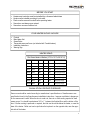
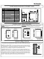
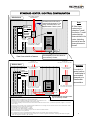
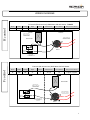
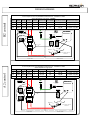
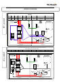
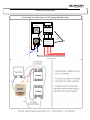
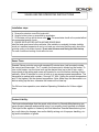
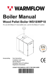
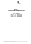
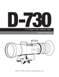
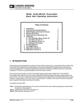
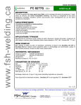
Heater Model __________ Serial # __________ ULTRA-SAUNA HEATER Proudly made in USA since 1964 MEDIUM HEATERS 6.0-9.0 KW Installation Instructions & User Manual ULTRA-SAUNA HEATER INSTALLATION INSTRUCTIONS— Medium Heaters 6.0-9.0 1 BEFORE YOU START Heater and controls must be installed by a licensed electrician Heater must be installed according to local codes. Plastic must be removed from shell before operating heater. Sauna door must always open outward. Sauna door can never include a lock. YOUR HEATER SHOULD INCLUDE Controls Main Heater Unit Sauna Rocks Thermostat sensor wall cover (not included with T-model heaters) Installation Instructions Warning Sign HEATER SIZING Ultra Sauna Heaters—Medium (16” W x 14” D x 28-3/4” H) Model Watts Volts Phase Amps Max Room Size 60240 6000 240 1 25 42 sq ft (12.8 sq m) 60208 6000 208 1 28.9 42 sq ft (12.8 sq m) 75240 7500 240 1 31.3 64 sq ft (19.5 sq m) 75208 7500 208 1 36.1 64 sq ft (19.5 sq m) 90240 9000 240 1 37.5 88 sq ft (27 sq m) 90240-3 9000 240 3 21.7 88 sq ft (27 sq m) 90208 9000 208 1 43.3 88 sq ft (27 sq m) 90208-3 9000 208 3 25 88 sq ft (27 sq m) SAUNA ROOM VENTING GUIDELINES Sauna room should be vented according to manufacturer’s specifications or Scandia sauna room specification found in the Scandia sauna installation instructions. Improper ventilation is dangerous for the sauna user’s health. When the door is under cut, there is no other venting required in small sauna rooms. You should have between 3/4” to 1” between the finished floor and the bottom of the door. If further venting is preferred or required, the inlet vent should be below the heater, or near the base of the heater. Outlet vent can be just below the top bench on the opposite side, near the opposite side of the heater. 2 SAUNA HEATER GUARD RAIL PLACEMENT GUIDE A B C D E F G H I J CHASSIS To Ceiling (H-7ft) MEDIUM Description Width Of Heater Shell Wall to Face of Heater Side of Heater to Wall (Min.) Height of Heater Shell Wall to Inside of Guard (Min.) Lower to Upper Mounting F.F. to Bottom Mount Heater Center to Wall (Min.) F.F. to Bottom of Heater Top of Heater to Ceiling (7ft.) 6.0KW‐9.0KW 16" 14" 5" 28 3/4" 19" 22 1/2" 14" 13" 10" 40" J A H C To wall or guard rail C L E F D G B H I Minimum dimensions of heater guard must be 26” L x 19” d x 33-3/4” H—Top rail of guard must be below heater vent CONTROL PANEL MODELS AND SIZES F control: suitable for heater model 60240, and heaters F Control Rough-In Dimensions with remote contactors. Control Cover Plate A/B control: suitable for heater models 60208, 75240, A/B Control Rough -In Dimensions 75208, 90240, 90208 (standard or T-model heaters) Control Box Control Cover Plate 9 ¾” Control Box 8 ¼” 4" 6" 4" 3 " 14 ¼” 12 ¼” 8" 10 1/2" 0 0 45 15 45 15 30 30 22ga Brushed Aluminum 22 ga Brushed Aluminum I8 ga Galvanized Paint-loc Steel I8 ga Galvanized Paint -loc Steel * NOTE: rough-in ½” extra on box dimensions CONTROL PANEL LOCATION All controls must be mounted on the outside of the sauna, NEVER inside the room. COMMERCIAL INSTALLATION – for 60-min timer, follow the residential installation recommendations. For 24-hour timer, you may place the control panel either in front of the sauna or in the mechanical or electrical room away from the sauna room. Please note that the thermostat capillary tube is only 4 ft long, therefore for controls placed away from the sauna, we recommend T-model heaters, where the thermostat is built in the heater itself. 12" Door opens on the right RESIDENTIAL INSTALLATION – For convenience, place the control box at eye level by the door, approximately 12” from the door opening and 52” from the floor (see fig. 1). For conduit and wire size, type and quantities, see specific heater wiring diagram charts. Sauna exterior wall 52" 3 STANDARD HEATER / CONTROL CONFIGURATION Line Feeds /Ground From B reaker 60-min timer Thermostat sensor bulb must be the sauna 10” from ceiling—horizontal position. Use supplied bracket to hold it in place. Note: Therm ostat mounted inside S ensor B ulb Control panel on the outside of sauna room. Recessed mounted. All Ultra-Sauna heaters can be ordered as T-model from factory. T-model heaters have the thermostat built in the heater, eliminating the need to have the thermostat sensor in the wall. C ontrol Box H eater W arning Signs Line feeds/ground from C ontrol box to H eater Wall mounted inside sauna room 10-12” View from outside of sauna Recommended grill vent below heater improves efficiency of heater. O p t io n # 1 C o n t ro ls n e a r d o o r 24-hour timer O p t io n #2 C o n t ro ls in re m ot e lo c a t io n Important: Control panel on the outside of sauna room. Recessed L in e F e e d s / G ro u n d F ro m B re a k e r L in e F e e ds / G ro u n d F ro m B re a k e r C o n tro ls b e h in d c o v e r (2 4 ho u r tim er ) C o n tr o ls ( 2 4 ho u r tim er) H eater L in e f e e d s / g ro u n d f ro m C o n t ro l b ox t o H e a t e r Wall mounted inside sauna room For controls in remote locations, T-model heater is recommended, please ask your Scandia sales representative. L in e f e e d s / gro u n d f ro m C o n t ro l b o x t o H e a t e r 10-12” IM P O R T A N T N O T E S: - Recommended grill vent below heater improves efficiency of heater. H e a t e r m u s t b e in s t a lle d b y a lic e n s e d e le c t ric ia n . H e a t e r m u s t b e in s t a lle d in s id e t h e s a u n a ro o m a n d m o u n t e d o 10-12” n e f o o t f rom t h e f lo o r . C o n t ro ls m u s t b e in s t a lle d o u t s id e o f t h e s a u n a ro o m . T h e rm o s ta t c a p illa ry s e n s o r b u lb m u s t b e lo c a t e d in s id e t h e s a u n a ro o m (h o riz o n t a l p o s it io n ) a p p ro x . 1 0 in c h e s f ro m c e ilin g . A ll w irin g m u s t c o m p ly w it h L o c a l a n d S ta t e o rd in a n c e s : a ll w irin g in t o t he s a u n a ro o m m u s t b e ra t e d f o r a t le a s t 9 0 d e g re es C e ls iu s (1 9 4 d e g F a re n h ie t ). S t a n d a rd s a u n a c e ilin g h e ig h t is 7 f e e t . C o n s u lt all lo c a l c o d e s b e f o re in s t a lla t io n . W a rn in g sig n s m u s t b e in s t a lle d a t e y e lev e l o n d o o r a n d a b o v e h e a t e r . D o o r m u st a lw a y s s w in g o u t w a rd . A ir in t a k e v e n t m u s t b e in s t a lle d b e lo w h ea t e r a n d a n a ir e x h a u s t v e n t s ho u ld b e in s t a lle d . T h e rm o s ta t s h o u ld b e p la c e d b e h in d c o v er a n d o u t o f c o n t ro l o f g u e s t s / m e m b e rs . S e t t in g s h o u ld b e n o h ig h e r t h a n 1 8 0 d e g re e s f a re n h e it (8 5 C e lc iu s) 4 WIRING DIAGRAMS H control H Controls (for T-Model Heaters) Series 30 Watts 3000 Series 45 Watts 4500 60 60 6000 6000 3000 W atts to 6000 W atts Hea ters Volts Am ps Phase Mas Room Size Circuit Breaker W ires from control to heater B Controls (60 minute timer) 6000 Watts 240 Volt Heater ‐ T‐Model 240 / 208 12.5 / 14.4 1 20 sq ft 20 3 qty #14 ga H Controls (for T-Model Phase Heaters) 3000 W atts to 6000 W atts Heaters Voltage Amps Max Room Size Circuit Breaker Wires (Control to Heater) 1 30 sq ft 3 qty #10 ga 240 / 208 18.8 / 21.7 30 240 / 208 240 Single-phase only 240/208 H Controls (thermostat on heater )Volts 42 sq ft 30/40 1 1240V Sing le phase 42 sq ft 30 3 qty #10 ga 3 qty #8 ‐ 2 qty #14 25 25 / 28.9 Heater Controls H igh -Limit Line Timer to H igh -Limit on Base of H eater Power Feed W ires Pow er to L1 and L 2 Thermostat T1 L1 T2 H igh Limit L2 Timer H eater Element s H eater Elem ent Line T2 t o heater element s F control Series Series 3030 4545 60 6060 Series F Controls (60 minute timer) 3000 Watts to 6000 W atts Heaters Single-phase only 240/208 Volts Watts Watts 3000 3000 4500 4500 6000 6000 6000 Watts F Controls (60 minute timer) 6000 Watts 240 Volt Heater Phase MasRoom RoomSize Size Circuit Circuit Breaker Wires Wires from control to heater Phase Mas Breaker from control to heater Volts Volts Amps Am ps 240 240 //208 208 240 //208 208 240 240 / 208 240 240 / 208 12.5 / 14.4 14.4 Amps 18.8 / 21.7 21.7 2525 // 28.9 25 28.9 Voltage 11 11 Phase 2020sqsqft ft Max Room Size 3030sqsqft ft F Control s (60 min ute timer 11 4242 sqsq ft ft 1 42 sq ft version ) 240V S ingle Phase 2020 Circuit Breaker 3030 30/40 30 30/40 Heater 3 qty 3 qty #14#14 ga ga Wires (Control to Heater) 3 qty #10#10 ga ga 3 qty 33 qty #8 ‐ 2 qty #14 qty #10 ga ga 3 qty #10 Co ntrols Thermostat High -Limit Line Timer to H igh- Limit on Base of Heat er High Limit P ower Feed W ires Pow er to L1 and L2 T1 Heat er Elem ents H eater Element Line T2 t o heater elem ents L1 T2 Timer L2 5 WIRING DIAGRAMS B2 control Series 60 B Controls (60 minute timer) 6000 Watts 208 Volt Heater ‐ 7000 Watts to 9000 Watts 240/208 Volt single phase ‐ T‐Models B C o n tro ls ( 6 0 m in u te tim e r) 7 5 0 0 W a tt s to 9 0 0 0 W a t ts H e a te rs Watts Voltage Amps Phase Max Room Size Circuit Breaker Supply Wires (Inc.Ground) Wires (Control to Heater) 6000 Se ries 75 75 90 90 S in g le -p h a se o n ly 2 4 0 / 2 0 8 V o lts. F o r T -M o d e l H e a te r s 208 28.9 W atts 1 Vo lts 42 sq ft Am ps P ha s e 7500 240/208 31.3 / 36.1 750 0 240 / 20 8 31.3 1 / 36.1 900 0 240 / 20 8 9000 240/208 37.5 / 43.3 S In g l e P h a s e P owe r F eed 1 56 sq ft 1 1 37.5 / 43.3 1 80 sq ft 40 3 qty #8 M as Ro om S ize C irc ui t B reak e r 56 s40 q ft 80 s q ft 3 qty #8 40 50 50 3 qty #8 ‐ 2 qty #14 W ir es fr om c ontro l to h eater 3 qty #8 3 qty 3 qty #8 ‐ 2 qty #14 # 8 ga - 2 q ty #14 3 qty # 8 ga - 2 q ty #14 3 qty #8 ‐ 2 qty #14 G ro u n d 2 S c a n di a el ec tr i c h e at e r s a r e U L lis t e d G r ound T e rm in a l Ti m e r C o n ta cto r H i g h L i m it S w i tc h T -s ta t To c on ta c tor c o ils 1 2 To co n t a cto r c o i ls C o n ta cto r Ele m e n t 2 E le m e n t 1 1 1 3 2 4 ** 9kw heaters will have 3 elements ** 2 Co n tro l B o x S a un a He a t er A Controls (60 minute timer) 7500 Watts to 9000 W atts Heaters Single-phase only 240/208 Volts A2 control Series A Controls (60 minute timer) 6000 Watts 208 Volt Heater ‐ 7000 Watts to 9000 Watts 240/208 Volt single phase Watts Voltage Amps Phase Max Room Size Circuit Breaker Supply Wires (Inc.Ground) 6000 75 7500 240/208 31.3 / 36.1 1 m inute 56 sq ft A Co ntro ls (60 tim e r) 7500 40 W atts to 90003 qty #8 W atts He a te rs 3 qty #8 ‐ 2 qty #14 S ingle -phase o nly 240/ 208 Vo lts 3 qty #8 ‐ 2 qty #14 9000 240/208 37.5 / 43.3 1 80 sq ft 50 3 qty #8 SI ngle P hase P owe r Fee d 28.9 1 2 1 42 sq ft 40 3 qty #8 Wires (Control to Heater) 60 90 208 3 qty #8 ‐ 2 qty #14 Gro und Scandi a electric heaters are U L li sted Grou nd Termina l T-stat C onta ctor 1 2 To co ntacto r coi ls H ig h Lim it Sw itch To con tactor coils Tim er C onta ct or E leme nt 2 Elem ent 1 2 1 1 2 Con trol Box 3 4 ** 9kw heaters will have 3 elements ** S auna H eate r 6 WIRING DIAGRAMS Series Series B3 control 90-3 120-3 90 A3 Controls (60 minute timer) 9000 Watts to 12000 Watts Heaters B3 Controls (60 minute timer) 9000 Watts 240/208 Volt 3 phase ‐ Three-phase only 240/208 Volts T‐Model Watts Volts Amps Watts Voltage 9000 240 / 208 12000 240 / 208 Amps 21.7 / 25 29 / 33.4 9000 240/208 21.7/25 Th re e Ph Phase ase Three Power wer Fe Feed ed Po 2 13 2 1 Phase Mas Room Size Circuit Breaker Phase Max Room Size Circuit Breaker 3 80 sq ft 3 3 3 120 sq ft 80 sq ft Supply Wires (incl ground) Supply Wires (Inc.Ground) 4 qty #8 ga 60 40 40 50 Wires from control to heater Wires (Control to Heater) 4 qty #8 ga - 2 qty #14 4 qty #8 ga 40 4 qty #8 ga - 2 qty #14 4 qty #10 4 qty #10 ‐ 2 #14 Grou ndGround Sc andi a el ectri c heaters Sc andi a el ectri c heaters are U L l isted are U L l isted Gro und Ground Terminal Terminal TT-stat -stat tor CContacCtoontac r 11 22 T -stat High Limit High L imit o actor ls To To contactor contactor coils coils High Limit S witc h S witc h S witc h Tim er Timer To To contactor contactor coils coils 1 2 Contact or Con C ta ct or Element 3 Element 3 Element 2 Element 2 Element 1 Element 1 12 1 11 2 1 3 2 To To Hig Highh Lim it Limit 3 2 34 5 6 45 6 3 Sauna Heater Sauna H eater Sauna H eater Control Control Box Box A3 Controls (60 minute timer) 9000 Wa tts to 120 00 Wa tts Hea ters Three-phase only 240/208 Volts A3 control Series Volts Amps 90-3 Watts 9000 240 / 208 21.7 / 25 Phase 3 120-3 12000 240 / 208 29 / 33.4 3 Th re e Ph ase Po wer Fe ed 1 2 3 Mas Room Size Circuit Breaker 80 sq ft 60 120 sq ft 40 Supply Wires (incl ground) 4 qty #8 ga Wires from control to heater 4 qty #8 ga - 2 qty #14 4 qty #8 ga 4 qty #8 ga - 2 qty #14 Grou nd Sc andi a el ectri c heaters are U L l is ted T -stat Gro und Term inal C on tac to r 1 Tim er 2 High L imit S witc h To contactor coils To contactor coils C on ta ct or El ement 3 Ele me nt 2 Ele ment 1 1 To H ig h Lim it 1 2 2 3 4 5 6 3 Con trol Box Saun a H eate r 7 WIRING DIAGRAMS Converting 60 minute timer to 24 hr programmable timer. L1 T1 T -s ta t C o n ta c to r 1 T im er T2 L2 2 To c o n t a c t or c o il s To c o n t a c t or c o il s C o n ta c t o r L T T o H ig h Lim it 1 2 3 C o n tro l B o x T1 L1 L2 T2 8 SAUNA HEATER OPERATING INSTRUCTIONS Installation steps: A. Remove the protective cover off the heater shell. B. Hang the heater in place or as specified by manufacturer. C. Fill the heater rock tray with the sauna rocks. Note: This sauna heater should not be operated without the recommended quantity of rocks. D. ENSURE GOOD AIR CIRCULATION AROUND SENSOR BULB. Install the heater guard around rail around heater. After installation is completed, the heater should be turned on to maximum temperature for one hour to break any rocks having fault lines and to burn off the protective coating on the heater elements. Do not enter the sauna room during the initial start-up. The smell of smoke and cracking of rocks will not re-occur. Sauna Timer: Scandia’ Sauna controls come with standard 60 minute timer (wall mounted outside the sauna) and thermostat . For T models, the thermostat is located on the heater. To turn on the heater, turn the timer knob up the desired time (up to the 60 min. mark). Leave knob at the setting and sauna will operate for one hour before shutting off automatically. Allow 30 minutes for room to heat up to an average sauna temperature. The thermostat is marked with numbers 1 through 10. With 1 being the coolest temperature and 10 the highest. Set the desired temperature. Note: Make sure the thermostat is on before setting up the time, otherwise the heater will not heat up.’’ For 24-hour timer operation, see attached Operating Guidelines for 24-hour digital timer. Product Liability: The buyer acknowledges that the goods sold to them by Scandia Manufacturing can cause property damage and personal injury if not properly sized, handled or installed. The buyer further agrees to indemnify and hold harmless Scandia Manufacturing from any or all claims for damage, loss and/or liability arising out of improper handling, sizing and/or installation of goods. 9 Programming Instructions 24 digital hour timer To Set or Change the Day and Time: To clear entire memory, press key. Hold down the CLOCK key while pressing either the DAY, HOUR or MINUTES keys. Continue pressing until the desired day or number is shown. Then simply lift finger off of the CLOCK key to set. Display To Set Program (ON/OFF times): Reset port to cancel all prior settings Press TIMER key once to enter into program mode. Display will show “1 ON - - - - “ Press DAY key to choose any of 15 different day combinations for the first ON time. Note: days of the week having the same program should be copied by selecting the desired combination of days. Press the HOUR key and then the MINUTE key to select the desired first ON time. ON/AUTO/OFF Selection Key Indicator LED “ON” when connected to power source and contacts are closed. Press TIMER key once. Display will show “1 OFF - - - - “. Repeat previous step to select the desired OFF time. Repeat the entire sequence to complete up to eight ON/OFF times as desired. When programming is done, press the CLOCK key then the MANUAL key repeatedly until the indicator bar is above the word “AUTO” To Review Program: Press TIMER key repeatedly. When done, press CLOCK key to return to the time of day. To Cancel/Change Part of the Program: Press TIMER key repeatedly until the particular ON or OFF time appears, the repeatedly press the DAY key until the display show “ - - - - “ Set new ON and OFF time. ( See: To Set Programs ) To Override Automatic Operation: Press MAMUAL key to move indicator bar to the desired ON or OFF position. Note: Timer will not resume automatic operation until indicator bar is repositioned above the word AUTO. 10 ULTRA SAUNA - WARRANTY Your Ultra Sauna heater has been engineered and built to the highest quality standards, and is backed by this warranty to assure your complete satisfaction: (1) SCANDIA Mfg warrants on the terms and conditions set forth below for ten years to the Original Owner only, at the Original Installation site only, this equipment to be free from defect in material and/or workmanship under normal use as specified in the equipment’s instructions, FROM DATE OF PURCHASE and thereafter. (2) A TEN YEAR LIMITED WARRANTY applies only on the heater unit as manufactured by and at SCANDIA Mfg., - Manufacturing Plant – and specifically excludes all components and/or parts which are accessories therein, namely: the gas valve; pilot generator: heating element; contactor; timer switch; thermostat; and, high limit, for which their respective manufacturers warranties apply. The TEN YEAR LIMITED WARRANTY does not apply for units that have been installed in commercial locations such as clubs, condominiums, apartments, spas or military facilities. In commercial locations, Scandia will provide a one-year warranty on the unit. (3) During the first year SCANDIA will, at its option, repair or exchange at the Factory all parts which it finds have become inoperative during said warranty period due to a defect in material or workmanship, without cost to customer except for freight and/or crating charges. (4) For the period commencing with the second year and for the ten year warranty of the original purchaser only, at the original installation only, SCANDIA will, at its option, repair or exchange at the Factory, all parts which it finds have become inoperative during said warranty period due to a defect in material or workmanship except the following parts which are excluded from this warranty: the gas valve; pilot generator: heating element; contactor; timer switch; thermostat; and, high limit. (5) This warranty in its entirety becomes null and void if unit is rented or to be used for rental purposes or installed in any mobile or fixed prefab rental room. If original purchaser is a corporation then, the president of said corporation, shall be construed as registered Original Owner for all purposes herein, otherwise this warranty in its entirety becomes null and void. (6) This warranty in its entirety becomes null and void if unit has been installed by an unlicensed party by and/or in the city and/or county where installation is made. Furthermore if unit is disassembled and/or tampered with in any way possible by any one (individual and/or company) then this warranty in its entirety becomes null and void. SCANDIA reserves the right to substitute new equipment or parts on any orders for replacement hereunder, but shall not be obligated to do so. This warranty is solely for the benefit of the original purchaser and no one else, and only if the installation and operating instructions applicable to the model purchased are followed. These instructions are furnished with the unit and also are available by writing SCANDIA’s warehouse. These instructions are incorporated herein by reference as if set forth in full. This warranty does not cover damages which appear to SCANDIA to have resulted from neglect, alteration, abuse, misuse, accident, flood, fore or other act of force majeure, or other than normal use. This warranty is expressly in lieu of other warranties, or liabilities, express or implied, by the Company or its representatives, and in lieu of all other obligations and liabilities for damage to persons or property caused in any manner by the heater or its component parts. More specifically, by not by way of limitation, SCANDIA assumes no liability for damages which may occur as a result of neglect or intentional misuse of the unit, and the purchaser or user of the unit agrees to assume all liability for the consequences of its use or misuse by such purchaser or user, and his, its or their respective employees and agents or other third person. THERE ARE NO WARRANTIES WHICH EXTEND BEYOND THE DESCRIPTION ON THE FACE HEREOF. NO REPRESENTATION OR WARRANTIES ARE MADE, EXPRESSED OR IMPLIED, OTHER THAN THOSE EXPRESSLY HEREIN SET FORTH TO THE ORIGINAL PURCHASER ONLY. To obtain the benefits of this Warranty, the inoperative parts and/or complete heater must be sent to Scandia, all shipping and crating charges prepaid. And all repaired or replaced parts or heaters will be returned freight collect. This warranty is effective only when the attached Factory Registration Stub is completed and returned to the manufacturer. Please contact Scandia for return authorization at 877-467-2862 or via e-mail [email protected] Warranty stub must be mailed or completed online within thirty DAYS TO REGISTER AND VALIDATE THIS WARRANTY, WHICH BECOMES VALID ONLY IF THE HEATER HAS BEEN PURCHASED DIRECTLY FROM SCANDIA MFG., AND/OR AUTHORIZED DEALERS IN U.S.A., its territories or possessions. TO VALIDATE WARRANTY VISIT WWW.SCANDIAMFG.COM/PRODUCT_REGISTRATION.HTML AND REGISTER YOUR PRODUCT. ALL PRODUCTS MUST BE REGISTERED PRIOR TO ANY WARRANTY CLAIMS. 11