1
INSTRUCTION MANUAL
R.C. SYSTEMS CO. INC.
MODEL ST-72 16,32,48 or 64 CHANNEL CONTROLLER
(Revision b 2.0 – Firmware 2.0 & later)
Warning: Read & understand contents of this manual prior to
operation. Failure to do so could result in serious injury or death.
PHONE: (409)986-9800 FAX: (409) 986-9880
8621 HWY 6 HITCHCOCK, TX 77563
Website: http://www.rcsystemsco.com
SECTION 1 GENERAL DESCRIPTION ............................................................. 1
1.1
1.2
1.3
1.3.1
1.3.2
1.3.3
1.3.4
1.3.5
1.4
IMPORTANT SAFETY ISSUES ......................................................................... 1
GENERAL DESCRIPTION................................................................................. 2
DATA DISPLAY SCREENS ............................................................................... 3
MAIN DATA SCREEN
24 HOUR TREND SCREEN
BAR GRAPHS SCREEN
COMBINATION SCREEN
ZONE SCREEN
3
5
6
7
8
SPECIFICATIONS ............................................................................................. 9
1.4.1 DC POWER SUPPLY REQUIREMENTS
9
1.4.1.1 600 WATT AC – 24VDC POWER SUPPLY
9
1.4.1.2 150 WATT AC – 24VDC POWER SUPPLY
9
1.4.1.3 RELAYS
10
1.4.2 AMBIENT TEMPERATURE RANGE
10
1.4.3 HUMIDITY RANGE
10
1.4.4 ALTITUDE
10
1.4.5 HOUSINGS
10
1.4.6 NON-INTRUSIVE MAGNETIC KEYPAD
10
1.4.7 APPROVALS
11
SECTION 2 BASIC OPERATION .................................................................... 12
2.1
2.2
2.3
MAIN MENU CONFIGURATION ...................................................................... 12
CHANGING MENU VARIABLES USING THE KEYPAD ................................. 20
ALARM OUTPUTS .......................................................................................... 20
2.3.1 STANDARD RELAY 1, 2, AND 3
2.3.1.1 A1 A2 & A3 VOTES REQUIRED
2.3.1.2 ACKNOWLEDGE
2.3.1.3 FAILSAFE
2.3.1.4 ZONE 1-8
2.3.1.5 OVERRIDE CHANNELS 1-8
2.3.2 HORN/PIEZO
2.3.2.1 A1 A2 & A3
2.3.2.2 ACKNOWLEDGE
2.3.2.3 FAILSAFE
2.3.2.4 PIEZO ALARM
2.3.3 DISCRETE RELAY
2.3.4 PROGRAMMABLE RELAY
2.4
22
22
22
22
23
23
23
23
24
24
24
24
25
CHANNEL CONFIGURATION ENTRY MENU ................................................. 25
2.4.1 CHANNEL CONFIGURATION MENUS
2.4.2 ALARM 1 / ALARM 2 / ALARM 3 MENU
2.4.2.1 SETPOINT
2.4.2.2 LATCHING
2.4.2.3 TRIP ON
2.4.2.4 ON/OFF DELAYS
2.4.2.5 HORN ON
2.4.2.6 COLOR
2.4.2.7 ENABLED
2.4.3 FAULT ALARM MENU
2.4.4 DATA FROM MENU TO SET INPUT SOURCE
1
26
27
27
27
27
27
27
28
28
28
28
2.4.4.1 SOURCE
2.4.4.2 MIN RAW & MAX RAW
2.4.4.3 FILTER SAMPLE COUNT
2.4.4.4 LOCAL CAL
2.4.4.5 MARKER MENU
2.4.4.6 REMOTE ID
2.4.4.7 ALIAS
2.4.4.8 INTERFACE
2.4.4.9 SLAVE BYTE ORDER
2.4.5 LINEARIZE
2.4.6 CONFIGURE MENU
2.4.6.1 INFO / MEASUREMENT NAME
2.4.6.2 ZERO / SPAN
2.4.6.3 DECIMAL POINTS
2.4.6.4 CHANNEL ON?
2.4.6.5 ZONE
2.4.6.6 DEADBAND
2.4.6.7 COPY TO CHANNEL
2.4.6.8 COPY TO GROUP
2.4.6.9 RESTORE CH. DEFAULTS
2.5
COMMUNICATION SETTINGS MENU ............................................................ 36
2.5.1 COM 1-4 SETTINGS
2.5.1.1 FUNCTION
2.5.1.2 BAUDRATE
2.5.1.3 PARITY
2.5.1.4 TIMEOUT
2.5.1.5 POLL DELAY
2.5.1.6 SYMPATHY ENABLED
2.5.1.7 RADIO SETUP
2.5.1.8 SLAVE BYTE ORDER
2.5.1.9 WIRELESS TIMEOUT
2.5.2 MODBUS TCP SETTINGS
2.5.2.1 SLAVE BYTE ORDER
2.5.2.2 MASTER TIMEOUT
2.5.2.3 MASTER POLL DELAY
2.5.3 NETWORK SETTINGS
2.5.3.1 DHCP ENABLED
2.5.3.2 HOSTNAME
2.5.3.3 IP ADDRESS
2.5.3.4 NETMASK
2.5.3.5 GATEWAY
2.5.4 TROUBLESHOOTING
2.5.4.1 VIEW COMM FAILURES
2.5.4.2 CLEAR FAILURE COUNTS
2.6
2.6.1
2.6.2
2.6.3
29
29
30
30
31
32
32
32
32
33
33
34
34
34
34
34
35
35
35
35
37
37
38
38
38
38
38
39
39
39
40
40
40
40
40
41
41
41
41
41
41
42
43
SECURITY MENU ............................................................................................ 43
USER NAME
LOCK CODE
MODBUS LOCK CODE
43
43
43
2
2.7
SYSTEM MENU ............................................................................................... 43
2.7.1 VERSION
45
2.7.2 CONFIGURE
45
2.7.2.1 NAME
46
2.7.2.2 CONTRAST
46
2.7.2.3 DATE & TIME
46
2.7.2.4 ENABLE CHANNEL COUNT
46
2.7.2.5 DISPLAY ALARM
46
2.7.2.6 WARMUP & CAL PURGE TIME
46
2.7.2.7 ZONE SCREEN ENABLED
46
2.7.2.8 BLOCK NEGATIVE
46
2.7.2.9 RELAY REFRESH
46
2.7.3 ZONE NAMES
47
2.7.4 MIMIC MODE
47
2.7.5 SD CARD
48
2.7.5.1 CARD STATUS
48
2.7.5.2 LOGGER ENABLED
49
2.7.5.3 SAVE CONFIGURATION FILE
49
2.7.5.4 LOAD CONFIGURATION FILE
49
2.7.5.5 VIEW LOG FILE TREND
49
2.7.6 VIEW EVENT LOG
50
2.7.7 CLEAR EVENT LOG
51
2.7.8 VIEW SENSOR LIFE
51
SECTION 3 INPUT/OUTPUT BOARDS ........................................................... 52
3.1
3.2
MAIN I/O INTERFACE BOARD # 10-0331 ...................................................... 52
INPUT / OUTPUT OPTION BOARDS .............................................................. 53
3.2.1 OPTIONAL ANALOG INPUT BOARD # 10-0334
54
3.2.2 OPTIONAL DISCRETE RELAY BOARD # 10-0345
56
3.2.3 OPTIONAL *BRIDGE SENSOR INPUT BOARD #10-0347
57
3.2.4 BRIDGE SENSOR INPUT BOARD INITIAL SETUP
58
3.2.5 OPTIONAL 4-20mA ANALOG OUTPUT BOARD #10-0348
59
3.2.6 OPTIONAL PROGRAMMABLE RELAY BOARD # 10-0350
60
3.2.7 OPTIONAL 24VDC 600 WATT POWER SUPPLY
62
3.2.8 OPTIONAL 24VDC 150 WATT POWER SUPPLY #10-0172
63
SECTION 4 DIAGNOSTICS ............................................................................. 64
4.1
4.2
4.3
4.4
4.4.1
4.4.2
4.5
4.6
4.7
4.8
4.9
STANDARD RELAYS ...................................................................................... 64
DISCRETE RELAYS ........................................................................................ 65
PROGRAMMABLE RELAYS ........................................................................... 65
ANALOG INPUTS ............................................................................................ 66
VIEW INPUTS
CALIBRATE BOARD
66
66
ANALOG OUTPUTS ........................................................................................ 67
PIEZO .............................................................................................................. 67
LEDS ............................................................................................................... 68
SERIAL PORTS ............................................................................................... 69
I/O BOARD CONFIGURATION........................................................................ 70
SECTION 5 MODBUS ...................................................................................... 71
5.1
5.2
MODBUS TCP ................................................................................................. 71
MODBUS SLAVE WRITES .............................................................................. 71
3
5.3
MODBUS SLAVE REGISTER LOCATION ...................................................... 71
5.3.1 COILS
72
5.3.2 DISCRETE INPUTS
72
5.3.3 INPUT REGISTERS
74
5.3.4 HOLDING REGISTERS
78
5.3.5 STANDARD RELAY 1
79
5.3.6 STANDARD RELAY 2
82
5.3.7 STANDARD RELAY 3
84
5.3.8 DISCRETE RELAYS
87
5.3.9 HORN/PIEZO
87
5.3.10 CHANNEL CONFIGURATION
88
5.3.11 PROGRAMMABLE RELAYS
91
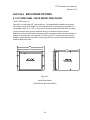
SECTION 6 ENCLOSURE OPTIONS .............................................................. 95
6.1
6.2
6.3
ST-72PM PANEL / RACK MOUNT ENCLOSURE ........................................... 95
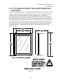
ST-72N4 NEMA 4X LARGE WALL MOUNT FIBERGLASS ENCLOSURE ..... 96
ST-72CP NEMA 4X COMPACT WALL MOUNT FIBERGLASS ENCLOSURE
97
6.4
ST-72XP NEMA 7 WALL MOUNT ALUMINUM ENCLOSURE ........................ 99
6.5
ST-72 MAIN I/O & OPTION PCB FOOTPRINT DIMENSIONS AND
ENCLOSURE CAPACITIES ....................................................................................... 100
SECTION 7 WIRELESS OPTION .................................................................. 102
7.1
7.1.1
7.1.2
7.1.3
7.2
RADIO SETUP MENU ................................................................................... 103
HOP CHANNEL
SYSTEM ID
MODE
104
104
104
WIRELESS MONITOR MODE ....................................................................... 104
7.2.1 RADIO STATUS ALARMS - WIRELESS MONITOR MODE
7.2.1.1 COMMUNICATIONS ERROR
7.2.1.2 LOW BATTERY
7.2.1.3 CALIBRATIONS
7.3
7.4
7.5
7.5.1
7.5.2
7.5.3
7.5.4
7.6
105
105
106
106
WIRELESS MODBUS SLAVE MODE............................................................ 106
WIRELESS MODBUS MASTER MODE ........................................................ 106
ANTENNA SELECTION ................................................................................ 107
DIPOLE AND COLLINEAR ANTENNAS
YAGI ANTENNAS
MOUNTING NEAR OTHER ANTENNAS
COAX CABLES
107
107
108
108
SURGE PROTECTION & GROUNDING ........................................................ 108
7.6.1 ANTENNA GROUNDING
109
SECTION 8 WEBPAGE ................................................................................. 111
8.1
8.2
8.3
8.4
8.5
8.5.1
8.5.2
8.5.3
8.5.4
SYSTEM SCREEN ......................................................................................... 112
ZONE SCREEN ............................................................................................. 113
CHANNEL SCREEN ...................................................................................... 114
EVENT LOG SCREEN ................................................................................... 115
CONFIGURE .................................................................................................. 116
ALARM OUTPUTS
CHANNEL CONFIGURATION
COPY CHANNELS
PROGRAMMABLE RELAYS
116
117
117
118
4
8.5.5 SYSTEM CONFIGURATION
118
8.5.6 CONFIGURATION UPLOAD/DOWNLOAD
119
SECTION 9 TROUBLESHOOTING ............................................................... 120
9.1
9.1.1
9.1.2
9.1.3
9.2
CHANNEL ERRORS...................................................................................... 120
COMM ERROR
CONFIG ERROR
I/O ERROR
120
120
120
RESET TO FACTORY DEFAULTS ............................................................... 121
SECTION 10 NETWORK CONNECTION ........................................................ 122
10.1
10.2
10.3
10.4
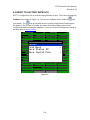
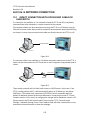
DIRECT CONNECTION WITH CROSSOVER CABLE OR HUB/SWITCH ..... 122
CONNECTING THE ST-72 TO AN EXISTING LAN ....................................... 123
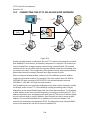
CONNECTING THE ST-72 ON AN ISOLATED NETWORK .......................... 124
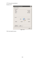
STATIC IP CONFIGURATION ....................................................................... 125
10.4.1 ST-72 STATIC IP CONFIGURATIION
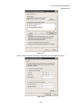
10.4.2 WINDOWS XP STATIC IP CONFIGURATION
10.4.3 DYNAMIC IP CONFIGURATION
10.5
125
125
128
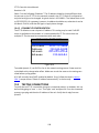
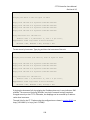
TESTING CONNECTIONS............................................................................. 128
5
REVISION HISTORY
Revision a 2.0
Revision b 2.0
9/11/2012
5/19/2014
Update Section 2, 3, 6 and add Revision History page
Update Section 2.7.4
1
ST-72 Controller Users Manual
Revision b 2.0
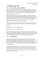
SECTION 1 GENERAL DESCRIPTION
1.1 IMPORTANT SAFETY ISSUES
The following symbols are used in this manual to alert the user of important instrument
operating issues:
This symbol is intended to alert the user to the presence of important
operating and maintenance (servicing) instructions.
!
!
This symbol is intended to alert the user to the presence of
dangerous voltage within the instrument enclosure that may be
sufficient magnitude to constitute a risk of electric shock.
WARNINGS:
Shock Hazard - Disconnect or turn off power before servicing this instrument.
WARNING- EXPLOSION HAZARD- DO NOT REPLACE FUSE UNLESS POWER HAS
BEEN SWITCHED OFF OR THE AREA IS KNOWN TO BE NON-HAZARDOUS.
!
!
WARNING- EXPLOSION HAZARD- DO NOT DISCONNECT EQUIPMENT UNLESS
POWER HAS BEEN SWITCHED OFF OR THE AREA IS KNOWN TO BE NONHAZARDOUS.
Use a properly rated CERTIFIED AC power (mains) cable installed as per local or
national codes
A certified AC power (mains) disconnect or circuit breaker should be mounted
near the controller and installed following applicable local and national codes. If
a switch is used instead of a circuit breaker, a properly rate CERTIFIED fuse or
current limiter is required to be installed as per local or national codes. Markings
for positions of the switch or breaker should state (I) for on and (O) for off.
Clean only with a damp cloth without solvents.
Equipment not used as prescribed within this manual may impair overall safety.
1
ST-72 Controller Users Manual
Revision b 2.0
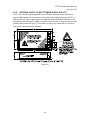
1.2 GENERAL DESCRIPTION
The R. C. Systems Co. Inc. ST-72 64 channel Controller is designed to display and control
alarm event switching for up to 64 sensor data points. It may also be set as a 16, 32 or
48 channel controller for applications needing fewer inputs. Three programmable
standard alarms with features such as ON and OFF delays, Alarm Acknowledge, along
with dedicated horn and fault relays make the ST-72 well suited for many multi-point
monitoring applications. Data may be input to the ST-72 by optional analog inputs or via
the multiple communication ports. These communication ports are programmable so
the controller can be configured with multiple Master or Slave configurations. With a
Modbus RTU slave RS-485 port configured, sending data to PCs, PLCs, DCSs, or even
other ST-72 Controllers is available. The Ethernet port allows the unit to be a
ModbusTCP Master and Slave and also provides access to the embedded webpage.
Options such as analog I/O and discrete relays for each alarm are easily added to the
addressable I2C bus. Option boards have 16 channels and therefore require multiple
boards for 64 channel applications.
In addition to traditional analog and serial methods of providing monitored values, the
ST-72 is also capable of sending and receiving wireless data.
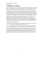
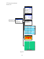
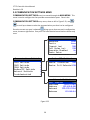
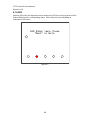
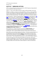
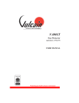
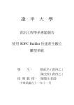
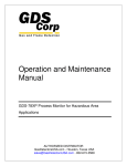
A color 320 x 240 pixel graphic LCD readout displays monitored data as bar graphs,
trends and engineering units. System configuration is through user friendly menus or
via the internal webpage that can be accessed through the Ethernet connection built
into the main I/O Board. All configuration data is retained in non-volatile memory
during power interruptions and can also be backed up and loaded using the SD card
located to the left of the display. The ST-72 front panel is shown below in Figure1-1
displaying the Combination screen. Additional data screens are shown in section 1.
2
ST-72 Controller Users Manual
Revision b 2.0
16, 32, 48, 64 Channel
Graphic Display & Alarm Controller
!
* DO NOT REMOVE
WHEN LED IS ON
Ch07
Measurement Name
PCTLEL
2400 Counts
Min:0
Max:95
Avg:32
Zero:0
Span:100
50
100 27
24
21
18
15
12
9
6
Menu
Alarm
Reset
Next
Edit
3m
SD Card
80
60
40
20
0
Serial No.
72-1020
Standard
Relay 1
Standard
Relay 2
Standard
Relay 3
Fault
Relay
Horn
Relay
Figure1-1
1.3 DATA DISPLAY SCREENS
The ST-72 Controller offers five distinct graphic displays for depicting the monitored
data. These are Main Data, 24 Hour Trend, Bar Graphs, Zone and Combination Screens.
Pressing
Menu
from any of these display screens will bring you to the Main Menu.
Edit
Pressing
from the Main Data, 24 Hour Trend or Combination Screens will skip the
Main Menu and bring you directly to the Channel Configuration Menu for the channel
that is selected.
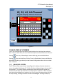
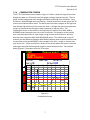
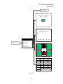
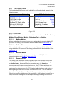
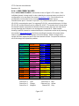
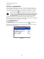
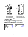
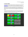
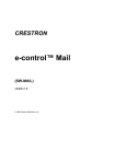
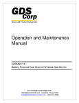
1.3.1 MAIN DATA SCREEN
The ST-72 Main Data screen shown below (Figure1-1) displays all active channels at
once. It is capable of displaying 16, 32, 48 or 64 channels depending on the controller’s
configuration. This screen displays measurement name and uses a bar graph and
colored cells that flash with new alarms to indicate alarm conditions. Once the alarms
have been acknowledged by an operator the cell will remain the appropriate color but
will stop flashing, showing the alarm has been acknowledged. Utilizing the Display
3
ST-72 Controller Users Manual
Revision b 2.0
Alarm feature in the Systems Configuration menu allows new alarms to always force the
LCD to the Main Data screen. This is useful for applications requiring channels with new
alarms to be displayed.
While in the Main Data screen, use
/
/
/
to highlight any cell and press
Edit
Next
to go directly to that channel’s configuration menu or press
twice to scroll
through that channel’s individual data screens. The exploded channel 38 in the example
below (Figure 1-2) indicates it is the channel selected and unused channels are grayed
out when turned off.
Measurement
%
Oxygen
Measurement
%
Measurement
Measurement
Measurement
Measurement
Measurement
Measurement
Measurement
Measurement
Measurement
ppm
H2S
Measurement
Measurement
Measurement
Measurement
Measurement
Measurement
Measurement
46PCTLEL
38
Measurement
Measurement
Measurement
Measurement Name
Measurement
Measurement
Measurement
Measurement
Measurement
Measurement
Measurement
Measurement
Measurement
Measurement
Measurement
%
Oxygen
Measurement
Measurement
Measurement
%
Oxygen
Measurement
Ppm
%
Oxygen
Measurement
Measurement
Measurement
Measurement
Measurement
Measurement
%
Oxygen
Measurement
Measurement
Measurement
Measurement
Measurement
Measurement
Measurement
Measurement
Measurement
Measurement
Measurement
Ch.
Ch.
Measurement
H2S
32
off
48
off
Figure 1-2
Main Data Screen (64 Ch. Mode)
4
Oxygen
ST-72 Controller Users Manual
Revision b 2.0
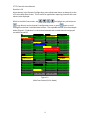
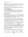
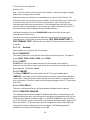
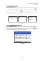
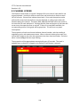
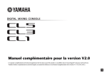
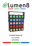
1.3.2 24 HOUR TREND SCREEN
The ST-72 24 Hour Trend screen shown in Figure 1-3 displays a 24 hour trend of input
data for the channel selected. Vertical tic marks are each hour and horizontal tic marks
are each 10% of full scale. Colored lines indicate alarm levels. The alarm level lines have
triangles on the right end that indicate high and low trip for each alarm level. A triangle
that points up represents a high trip alarm and one that points down represents a low
trip alarm. Since each data point must be collected for several minutes before it may be
displayed, it is likely input values will fluctuate during this interval. Therefore, MAX,
MIN and AVERAGE values are stored in RAM memory for each subinterval. To
accurately portray the trend, a vertical line is drawn between MIN & MAX values for
each subinterval. The AVERAGE value pixel is then left blank, leaving a gap in the
vertical line. This is demonstrated in the noisy area of the 24 hour trend in Figure 1-3. If
the MAX & MIN values are within 2% of each other there is no need for the vertical line
and only the AVERAGE value pixel is darkened as in the quiet areas. If there is no trend
data available, the corresponding section of the graph will be grayed out. This will occur
on power interruptions.
The top portion of each trend screen indicates channel number, real time reading in
engineering units, measurement name, range, and MIN, MAX & AVERAGE values for the
preceding 24 hour period. When a channel reaches alarm state, the colored bar
changes to the color that represents that alarm level and flashes. Once the alarm is
acknowledged the bar stops flashing.
Measurement
Zero: 0
Min: 1
100
20Hr
Name
Span: 100
MAX: 82
16Hr
12Hr
80
60
40
20
0
Figure 1-3
24 Hour Trend Screen
5
45
ppmH2S
10/20/2010
Avg: 26
8Hr
4Hr
ST-72 Controller Users Manual
Revision b 2.0
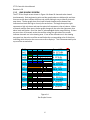
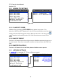
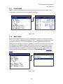
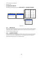
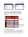
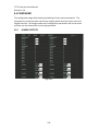
1.3.3 BAR GRAPHS SCREEN
The ST-72 Bar Graphs screen shown in Figure 1-4 allows 16 channels to be viewed
simultaneously. Both engineering units and bar graph values are indicated in real time.
Lines across the bars indicate the alarm trip points making it easy to identify channels
near alarm. The bar graph alarm lines have colored triangles on the bottom that
indicate alarm level and high or low trip for each alarm. A triangle that points right
represents a high trip alarm and one that points left represents a low trip alarm. When
a channel reaches alarm state, the bar graph changes to the color that represents that
alarm level and flashes. Once the alarm is acknowledged the bar stops flashing. If there
are more than 16 channels active the scroll bar along the right side of the screen
indicates channels not in the viewing area. If one of the channels not in the viewing
area goes into alarm the scroll bar arrow flashes the corresponding color of the alarm
indicating which direction the user must scroll to display it. This is demonstrated by the
top scroll bar arrow below.
Ch16
2
Ch17
54
PCTLEL
Ch18
18
PCTLEL
Ch19
6
PCTLEL
Ch20
4
ppmH2S
Ch21
67
ppmH2S
Ch22
28
PCTLEL
Ch23
13.6
%O2
Ch24
20.8
%O2
Ch25
ppmH2S
Fault
Ch26
75
PSI
Ch27
17
PCTLEL
Ch28
38
ppmH2S
Ch29
8
Ch30
15
Ch31
2
Figure 1-4
Bar Graphs Screen
6
ppmH2S
PCTLEL
ppmH2S
ST-72 Controller Users Manual
Revision b 2.0
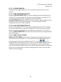
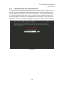
1.3.4 COMBINATION SCREEN
The ST-72 Combination screen shown in Figure 1-5 offers a view of a single channel but
displays the data as a 30 minute trend, bar graph and large engineering units. The bar
graph and the background color changes and flashes indicating alarm condition. Once
the alarm is acknowledged they stop flashing. Colored lines across the bar graph and 30
minute trend indicate alarm levels. The alarm level lines have triangles on the right end
that indicate high and low trip for each alarm level. A triangle that points up represents
a high trip alarm and one that points down represents a low trip alarm. The
Combination Screen is also useful for testing inputs for stability since MAX, MIN &
AVERAGE values reset each time this screen is selected. For example, to test stability
over a one hour period for an input, begin timing as soon as the channel is selected.
One hour later record the MAX, MIN & AVERAGE values. The visible trend is only 30
minutes, but the difference between MAX & MIN indicates peak to peak excursions over
the one hour period and AVERAGE is the average for the hour. Longer or shorter tests
may also be run. A blue vertical line is drawn on the screen when the screen is selected
and moves to the left indicating how long this screen has been active. The example
below (Figure 1-5) has been active for 26 minutes.
Ch07
Measurement Name
PCTLEL
2400 Counts
Min:0
Max:90
Avg:32
Zero:0
Span:100
50
100 27
24
21
18
15
12
80
60
40
20
0
Figure 1-5
Combination Screen
7
9
6
3m
ST-72 Controller Users Manual
Revision b 2.0
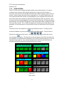
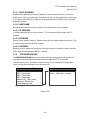
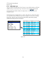
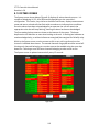
1.3.5 ZONE SCREEN
The ST-72 Zone screen displays the eight possible zones simultaneously. If an alarm
condition occurs the user will be able to quickly see in what zone the situation is
occurring. Each active zone is divided into alarm levels which are green until an alarm is
present. Inactive zones and alarm levels are grayed out. If an alarm should occur, the
zone name field will flash and the corresponding box in the assigned zone will turn the
color of the alarm that is present or alternate if two different colors are present. Once
the alarm has been acknowledged the name field will stop flashing. Utilizing the Display
Alarm feature in the Systems Configuration menu allows new alarms to always force the
LCD to the Zone screen. This is useful for applications requiring zones with alarms to be
displayed. If the Zone feature is not utilized this screen can be turned off in the Systems
Menu.
The Zone screen is also helpful for configuring the different zones. To display all the
channels included in any zone, press
Edit
while in the Zone screen. This will cause a
blue box to outline one of the zones. Use
/
/
/
to select the correct
Edit
zone and press
again. The Main Data screen will appear with all the channels that
are included in the selected zone displayed in color and the channels that are not in the
selected zone grayed out. Any channel needed to be included or excluded from the
selected zone can be selected and configured from this screen.
North
A1
Tank
A1
West
A1
Entrance
A2
A3
F
A1
Farm
A2
A3
Main
F
A1
Gate
A2
A3
Switchgear
A1
Control
A2
A3
ZONE
F
A1
Room
ZONE
F
A1
Figure 1-6
Zone Screen
8
A2
Room
A3
F
Process
A2
A3
F
A3
F
A3
F
7
A2
8
A2
ST-72 Controller Users Manual
Revision b 2.0
1.4 SPECIFICATIONS
1.4.1 DC POWER SUPPLY REQUIREMENTS
Standard ST-72 power requirements are 10-30VDC @ 12 watts applied to terminals 1 &
3(+) and 5 & 7(-) of TB4 on the standard I/O Board (see section 3.0). Optional features
increase power consumption as described below:
Discrete Relay Board option; add 6.5 watts per board (assumes all 16 relays are
energized).
Programmable Relay Board option; add 6.5 watts per board (assumes all 16 relays
are energized).
Analog Input Board option; add 1/2 watts per board plus transmitter power
consumption.
4-20mA Output Board option; add 2.5 watts per board.
Bridge Sensor Input Board option; add 3 watts max per board with eight 10-0192
modules installed (power consumption of the sensors not included).
Auxiliary Standard Relay Board option; add 2.5 watts.
Isolated Serial Expansion Board; add 1.5 watts.
TB4 terminals 2, 4, 6 & 8 of the standard I/O Board provide a maximum of 500mA
fused output power for powering of auxiliary external devices such as relays, lamps
or transmitters. Power consumed from these terminals should be considered when
calculating system power consumption.
1.4.1.1 600 WATT AC – 24VDC POWER SUPPLY
*110-120 VAC @8.5A max
*220-240VAC @ 5A max
* Universal AC input automatically selects AC input range.
The 600 watt power supply (Figure 3-7) is for powering the ST-72 and up to 64
detectors. This power supply can be paralleled with up to three additional 600 watt
power supplies providing up to 2400 watts for applications with large power
requirements. It also features a built in DC-OK signal and remote on-off control.
1.4.1.2 150 WATT AC – 24VDC POWER SUPPLY
*110-120 VAC @3.2A max
*220-240VAC @ 1.6A max
* A slide switch on the front of the power supply selects AC input range.
The 10-0172 150 watt power supply (Figure 3-7) is for powering the ST-72 and up to 64
detectors.
9
ST-72 Controller Users Manual
Revision b 2.0
1.4.1.3 RELAYS
The ST-72 comes standard with five Standard SPDT 5A relays, consisting of one
dedicated HORN and one dedicated FAULT relay plus 3 programmable alarm relays.
Programmable relays provide voting logic for ALARM 1, ALARM 2, and ALARM 3.
Discrete relays and additional Programmable relays are optional. All relays are rated at
5 Amp for 28 VDC and 250 ~VAC RESISTIVE loads.
!
IMPORTANT: Appropriate diode (DC loads) or MOV (AC loads) snubber devices
must be installed with inductive loads to prevent RFI noise spikes. Relay wiring should
be kept separate from low level signal wiring.
1.4.2 AMBIENT TEMPERATURE RANGE
-25 to 60 degrees C
1.4.3 HUMIDITY RANGE
0 TO 90% R. H. Non-Condensing.
1.4.4 ALTITUDE
Recommended up to 2000 meters
1.4.5 HOUSINGS
*General purpose panel mount weighing 7 lbs and including hardware for 19” rack
mounting (
Figure 6-1).
*NEMA 4X wall mount in fiberglass enclosure weighing 54 lbs (
Figure 6-2).
*Includes non-intrusive magnetic keypad.
1.4.6
NON-INTRUSIVE MAGNETIC KEYPAD
The ST-72 operator interface includes eight front panel touch keys
Menu
/
Alarm
Reset
/
Next
/
Edit
/
/
/
/
. A magnetic keypad option offers these eight keys with adjacent
magnetic keys. This option is included as a standard feature. It is useful in applications
where it may be inconvenient to open the enclosure’s door to access the touch keypad.
10
ST-72 Controller Users Manual
Revision b 2.0
1.4.7 APPROVALS
C22.2 No. 142-M1987 - Process Control Equipment
CAN/CSA-C22.2 No.152-M1984 - Combustible Gas Detection Instruments
ANSI/ISA-12.13.01-2000 - Performance Requirements for Combustible Gas Detectors
CSA-C22.2 No. 213-M1987- Non-Incendive Electrical Equipment for Use in Class I,
Division 2 Hazardous Locations
UL Std No. 1604, Third Ed. - 1994 - Electrical Equipment for Use in Class I and II, Division
2; Class III Hazardous (Classified) Locations
ANSI/ISA-12.12.01-2010 - Non-Incendive Electrical Equipment for Use in Class I and II,
Division 2 and Class III, Divisions 1 and 2 Hazardous (Classified) Locations
CSA File # = 219995 and may be seen at: CSA-International.org.
11
ST-72 Controller Users Manual
Revision b 2.0
SECTION 2 BASIC OPERATION
The ST-72 offers 5 graphic screens for viewing monitored data and several Set-Up menu
screens for operator interface to configuration menus. The Main Data screen allows
viewing of all active channels simultaneously. The Trend screen displays a 24 hour trend
one channel at a time. The Combination screen displays a bar graph, large engineering
units and a 30 minute trend one channel at a time. The Zone screen displays the eight
possible zones simultaneously. Input channels may be displayed in sequence from the
Next
Trend and Combination screens with
/
.
switches between the 5 graphic
data screens. When ST-72 power is applied, the graphic LCD starts in the Main Data
screen.
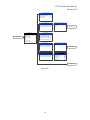
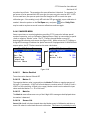
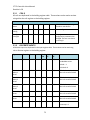
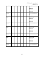
2.1 MAIN MENU CONFIGURATION
Variables inside Main menu tree allow optimum ST-72 configuration for a wide range of
demanding multi-point monitoring applications. The main menu is entered by pressing
Menu
Channel configuration menus are entered by pressing
Edit
from any channel’s data
Edit
screens, and scrolling to the desired menu using
/
. Pressing
again enters
the selected menu’s tree of variables. This Setup mode may be exited manually by
Next
pressing
or automatically when no keys are pressed for 5 minutes. Alarm relays
and front panel alarm LED indicators remain active during the Setup mode. A Security
menu offers a password feature to prevent tampering with ST-72 parameters. See
Figure 2-1 – Figure 2-7 for a complete ST-72 menu tree layout.
12
ST-72 Controller Users Manual
Revision b 2.0
Standard
Relay
A1
Votes
Required
1
A2
Votes
Required
0
A3
Votes
Required
0
Acknowledge
No
Failsafe
Zone
No
1
Yes
Override 1 Channel
Standard Relay Menus are
Identical
Horn/Piezo
Alarm
Outputs
Standard
Relay
1
~
Standard
Relay
2
~
Standard
Relay
3
~
Horn/Piezo
~
Discrete
~
Relay
Alarm
1
Alarm
2
Alarm
3
Beep
On
On
Acknowledge
Yes
Failsafe
No
Piezo
No
Alarm
Discrete
Channel
Config
Measurment
1 PCTLEL
Name
Ch.37
Measurment
46 PCTLEL
Name
Ch.38
Measurment
6 PCTLEL
Name
Ch.39
Main
Channel
~
Config
Communication
Security:
~
COM2
Settings
~
COM3
Settings
~
COM4
Settings
~
Settings
No
A3
Failsafe
No
Settings
Modbus
Timeout
Poll
9600
(ms)
Delay
Radio
500
(ms)
~
ModbusTCP
Slave
Security:
~
System
~
User
Name
Diagnostics
~
Lock
Code
Modbus
Unlocked
Default
Lock
User
Code
Byte
Timeout(ms)
Master
Poll
v1.00
Configure
~
Zone
~
Names
Card
View
Settings
Yes
Controller1
Address
192.168.0.100
Netmask
255.255.255.0
Gateway
192.168.0.1
~
Event
Clear
500
Delay(ms)250
Enabled
Hostname
System
View
ABCD
0
Network
SD
Settings
Order
Master
DHCP
Version
250
Setup
COM1-4 Menus are Identical
~
Settings ~
Master
BaudRate
~
Settings
~
Unlocked
No
Failsafe
Function
Settings
Settings
Network
Failsafe
A2
COM1
COM1
ModbusTCP
Menu
Outputs
Relay
A1
See Figure 2-2
Communication
Alarm
0
Event
Sensor
Log
~
Log
~
Life
~
See Figure 2-4
Entering Diagnostics mode. Inputs will not
be processed. Alarm relays and analog
outputs may change, causing undesirable
states affecting equipment connected to
this controller.
Ok
(Edit)
Cancel
(Next)
Diagnostics
Standard
Relays
~
Discrete
Relays
~
Programmable
Relays
~
Analog
Inputs
~
Analog
outputs
~
Piezo
~
LEDs
Serial
I/O
~
Ports
Board
Config
~
~
Figure 2-1
13
See Figure 2-5/2-7
ST-72 Controller Users Manual
Revision b 2.0
Ch.
38 Alarm
1
SetPoint
20
Latching
No
Trip On
High
On Delay (sec)
0
Off Delay (min)
0
Horn Drive
Yes
Ch. 38 Alarm 2
SetPoint
40
Latching
No
Trip On
High
On Delay (sec)
0
Off Delay (min)
0
Horn Drive
Yes
Color
Red
Ch. 38 Alarm 3
SetPoint
60
Latching
No
Trip On
High
On Delay (sec)
0
Off Delay (min)
0
Horn Drive
Yes
Color
Red
Enabled?
Channel Config
See Figure 2-1
Channel 38 Config
Alarm 1
~
Alarm 2
~
Alarm 3
~
Measurment Name Ch.38
46 PCTLEL
Fault Alarm
~
Data From
~
Measurment Name Ch.39
6 PCTLEL
Linearize
~
Configure
~
Measurment Name Ch.37
1 PCTLEL
Ch.
No
38 Fault Alarm
SetPoint
-10
Ch. 38 Data From
Src
Analog Input
Min Raw
800
Max Raw
4000
Filter Sample Count
Local Cal
10
See Figure 2-3
Board Default
Marker Menu
~
Ch. 38 Linearize
Input
Output
10.00
10.00
20.00
20.00
30.00
30.00
40.00
40.00
50.00
50.00
60.00
60.00
70.00
70.00
80.00
80.00
90.00
90.00
Ch. 38 Configure
Info
Measurement Name
Engineering Units PCTLEL
Zero
0
Span
100
Decimal Points
Channel On?
Zone
Deadband
Figure 2-2
14
0
Yes
1
(%)
1
Copy To Channel
~
Copy To Group
~
Restore Ch. Defaults
~
See Figure 2-3
ST-72 Controller Users Manual
Revision b 2.0
Ch.
38 Alarm
1
SetPoint
20
Latching
No
Trip On
High
On Delay (sec)
Off Delay
0
(min)
0
Horn Drive
Ch.
Yes
38 Alarm
2
SetPoint
40
Latching
No
Trip On
High
On Delay (sec)
Off Delay
0
(min)
0
Horn Drive
Yes
Color
Red
Ch.
38 Alarm
3
SetPoint
60
Latching
No
Trip On
High
On Delay (sec)
Off Delay
0
(min)
0
Horn Drive
Yes
Color
Red
Enabled?
Channel 38 Config
See Figure 2-2
Alarm 1
~
Alarm 2
~
Alarm 3
~
Fault Alarm
~
Data From
~
Linearize
~
Configure
~
Ch.
No
38 Fault Alarm
SetPoint
-10
Ch. 38 Data From
Src
Ch.
Analog Input
Min Raw
800
Max Raw
4000
Filter Sample Count
Local Cal
10
38 Marker Menu
Marker Enabled
Marker
%
Mark as
No
-16
IN CAL
Sensor Life
No
Board Default
Marker Menu
~
Ch. 38 Linearize
Input
Output
10.00
10.00
20.00
20.00
30.00
30.00
40.00
40.00
50.00
50.00
60.00
60.00
70.00
70.00
80.00
80.00
90.00
90.00
Ch.01 Copy To Channel
Copy To
2
Ch. 38 Configure
Info
Measurement Name
Engineering Units PCTLEL
Zero
0
Span
100
Decimal Points
Channel On?
Zone
Deadband
0
Yes
1
(%)
1
Copy To Channel
~
Copy To Group
~
Restore Ch. Defaults
~
Figure 2-3
15
Ch.01 Copy To Group
Copy To Group
Copy Now
Ch.01-16
~
ST-72 Controller Users Manual
Revision b 2.0
Configure
Name
Controller 1
Contrast
50
Date
10/20/2010
Time
09:43:28
Enable Channel Count 64
Display Alarm
Main Data
Warmup Time
1
Cal Purge Time (min)
1
Zone Screen Enabled Yes
Block Negative
Yes
Zone Names
System
Version
See Figure 2-1
v1.00
Zone 1
North Entrance
Zone 2
Tank Farm
Zone 3
West Gate
Zone 4
Switchgear Room
Zone 5
Control Room
Zone 6
Main Process
Zone 7
Zone 7
Zone 8
Zone 8
Configure
~
Zone Names
~
SD Card
~
Card Status OK
View Event Log
~
Logger Enabled
Clear Event Log
~
Save Config File
~
View Sensor Life
~
Load Config File
~
View Log File Trend
~
SD Card
YES
Time
Date
Event
Ch.
09:42
07/13/2010
Alarm 1 out
19
09:30
07/13/2010
Alarm Reset
09:28
07/13/2010
Alarm 1 in
19
08:15
07/13/2010
System Boot
--
21:37
07/12/2010
Alarm 1 out
07
21:35
07/12/2010
Alarm 2 out
07
21:30
07/12/2010
Alarm 2 in
07
21:28
07/12/2010
Alarm 1 in
07
17:56
07/09/2010
Comm Error
16
15:53
07/02/2010
Config Error
22
11:15
06/12/2010
Cold Boot
--
09:37
06/01/2010
Cal out
46
09:30
06/01/2010
Cal in
46
05:36
05/24/2010
Fault out
32
05:35
05/24/2010
Fault in
32
19
System
Version
V1.00
Configure
Are you sure you want to
clearNames
the event log?
Zone
SD Card
Yes (Edit)
No (Next)
View Event Log
Clear Event Log
Figure 2-4
16
~
~
~
~
~
Measurement
% Oxygen
Measurement
% Oxygen
Measurement
Measurement
Measurement
Measurement
Measurement
Measurement
Measurement
Measurement
Measurement
ppm H2S
Measurement
Measurement
Measurement
Measurement
Measurement
Measurement
Measurement
Measurement
Measurement
Measurement
Measurement
Measurement
Measurement
Measurement
Measurement
Measurement
Measurement
Measurement
Measurement
Measurement
Measurement
% Oxygen
Measurement
Measurement
Measurement
% Oxygen
Measurement
Ppm H2S
% Oxygen
Measurement
Measurement
Measurement
Measurement
Measurement
Measurement
% Oxygen
Measurement
Measurement
Measurement
Measurement
Measurement
Measurement
Measurement
Measurement
Measurement
Measurement
Measurement
Ch. 32 off
Ch. 48 off
Measurement
ST-72 Controller Users Manual
Revision b 2.0
Standard
Relay
Standard
Relay 1
Off
Standard
Relay 2
Off
Standard
Relay 3
Off
Fault
Horn
Relay
Off
Relay
Off
Discrete
Relay
Discrete
Relay
Ch.01-16
Discrete
Relay
Ch.01-16 ~
Alarm
1
~
Discrete
Relay
Ch.17-32 ~
Alarm
2
~
Discrete
Relay
Ch.33-48~
Alarm
3
~
Discrete
Relay
Ch.49-64~
Fault
~
See Figure 2-6
~
Programmable
Diagnostics
See Figure 2-1
Standard
Relays
~
Discrete
Relays
~
Programmable
Relays
~
Analog
Inputs
~
Analog
outputs
~
Piezo
~
LEDs
~
Serial Ports
~
I/O
~
Board
Config
Programmable
Rly.01
Off
Programmable
Rly.02
Off
Programmable
Rly.03
Off
Programmable
Rly.04
Off
Programmable
Rly.05
Off
"
"
Programmable
"
Rly.16
Analog
"
Off
Input
Analog
Input
Analog
Input
Ch.01-16
~
View
Analog
Input
Ch.17-32
~
Calibrate
Analog
Input
Ch.33-48
~
Analog
Input
Ch.49-64
~
Analog
Output
Ch.01-16
Inputs
~
Board
~
See Figure 2-6
Analog
Output
Ch.01-16
Analog
Output
Ch.01-16 ~
Analog
Out 1
Analog
Output
Ch.17-32 ~
Analog
Out 2
4mA
Analog
Output
Ch.33-48 ~
Analog
Out 3
12mA
Analog
Output
Ch.49-64 ~
Analog
Out 4
20mA
Analog
Out 5
16mA
"
Analog
"
"
Out 7
8mA
"
0mA
See Figure 2-7
Figure 2-5
17
ST-72 Controller Users Manual
Revision b 2.0
Discrete
Relay
Ch.01-16
Alarm
1
Alarm
1
~
Ch.01
Alarm
1
Off
Alarm
2
~
Ch.02
Alarm
1
Off
Alarm
3
~
Ch.03
Alarm
1
Off
~
Ch.04
Alarm
1
Off
~
Ch.05
Alarm
1
Off
Fault
"
"
Ch.16
Alarm
Raw
Analog
View
Input
Ch.01-16
Inputs
Calibrate
~
Board
~
See Figure 2-5
Analog
Output
Ch.01-16
Analog
Out
1
Analog
Out
2
4mA
Analog
Out
3
12mA
Analog
Out
4
20mA
Analog
Out
5
16mA
"
Analog
"
Out
"
7
8mA
"
0mA
Figure 2-6
18
"
"
1
Off
Counts
Raw
Counts
Ch.01:
001436
Ch.09:
001258
Ch.02:
002248
Ch.10:
001682
Ch.03:
003108
Ch.11:
002654
Ch.04:
001792
Ch.12:
003677
Ch.05:
003859
Ch.13:
002451
Ch.06:
001862
Ch.14:
001236
Ch.07:
001724
Ch.15:
002799
Ch.08:
002193
Ch.16:
001560
Calibrate
Board
Calibrate
Input
01
~
Calibrate
Input
02
~
Calibrate
Input
03
~
Calibrate
Input
04
~
Calibrate
Input
05
~
"
Calibrate
"
Input
"
"
16
~
ST-72 Controller Users Manual
Revision b 2.0
See Figure 2-5
Piezo Beep Test. Press
"Next"
To Exit.
BEEP!
LED
Blink Test. Press
"Next" To Exit.
Diagnostics
Standard
Relays
~
Discrete
Relays
~
Programmable
See Figure 2-1
Relays
~
Analog
Inputs
~
Analog
outputs
~
Piezo
~
LEDs
~
Serial
I/O
Ports
Board
Config
~
TXA
TXB
RXA
RXB
SUCCESS
COM1
~
RXA
RXB
Connect
Connect
COM1 to COM2 and COM3 to
TXA->RXA and TXB->RXB.
TXA
TXB
2
or
4
Wire.
RXA
RXB
RXA
RXB
COM4
TXA
TXB
Analog Input
Ch1 – Ch16
Analog Input
Ch17 – Ch32
Bridge Input
Ch33 – Ch48
Bridge Input
Ch49 – Ch64
Disc. Relay
Alarm 1
Ch1 – Ch16
Disc. Relay
Alarm 1
Ch17 – Ch32
Disc. Relay
Alarm 1
Ch33 – Ch48
Disc. Relay
Alarm 1
Ch49 – Ch64
Disc. Relay
Alarm 2
Ch1 – Ch16
Disc. Relay
Alarm 2
Ch17 – Ch32
Disc. Relay
Alarm 2
Ch33 – Ch48
Disc. Relay
Alarm 2
Ch49 – Ch64
Disc. Relay
Alarm 3
Ch1 – Ch16
Disc. Relay
Alarm 3
Ch17 – Ch32
Disc. Relay
Alarm 3
Ch33 – Ch48
Disc. Relay
Alarm 3
Ch49 – Ch64
Disc. Relay
Fault Alarm
Ch1 – Ch16
Disc. Relay
Fault Alarm
Ch17 – Ch32
Disc. Relay
Fault Alarm
Ch33 – Ch48
Disc. Relay
Fault Alarm
Ch49 – Ch64
Analog Out
Ch1 – Ch16
Analog Out
Ch17 – Ch32
Analog Out
Ch33 – Ch48
Analog Out
Ch49 – Ch64
Programmable
Relay
19
COM4.
FAILURE
COM3
Figure 2-7
COM2
TXA
TXB
ST-72 Controller Users Manual
Revision b 2.0
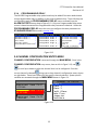
2.2 CHANGING MENU VARIABLES USING THE KEYPAD
Upon entering a menu, a blue highlight bar controlled by
/
indicates the
selected variable. Some are simple YES/NO or ON/OFF entries toggled by pressing
Edit
. Others, such as Measurement Name and Eunits fields may have many ASCII
character possibilities. Allowed ASCII characters are as follows:
ABCDEFGHIJKLMNOPQRSTUVWXYZ[\]^_`abcdefghijklmnopqrstuvwxyz{|}~ blank space
!"#→%&`()*+,-./0123456789:;<=>?@.
scrolls through each allowed entry.
field is complete,
Edit
Edit
places a cursor over the item and
/
/
move the cursor within a field. When the
clears the cursor and loads it into non-volatile memory where it is
retained indefinitely and
Next
will cancel any changes that have been made in the active
Next
field. With no cursor present,
closes open menus in reverse order and returns the
LCD to the most recent data display.
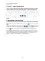
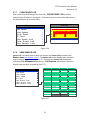
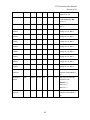
2.3 ALARM OUTPUTS
The menu item identified as ALARM OUTPUTS is accesses through the Main Menu.
Selecting it allows users to configure the different types of outputs that can be
connected to the ST-72 controller through the menu shown in Figure 2-8. The variables
under this menu are STANDARD RELAY 1, STANDARD RELAY 2, STANDARD
RELAY 3, HORN/PIEZO, DISCRETE RELAY, and PROGRAMMABLE RELAY
BOARD.
20
ST-72 Controller Users Manual
Revision b 2.0
Standard
A1
Votes
Required
1
A2
Votes
Required
0
A3
Votes
Required
0
Acknowledge
No
Failsafe
No
Zone
Alarm
Relay
1
Yes
Override 1 Channel
Standard Relay and Programmable
Relay Menus are Identical
Horn/Piezo
Outputs
0
Standard
Relay
1
~
Alarm
1
Beep
Standard
Relay
2
~
Alarm
2
On
Standard
Relay
3
~
Alarm
3
On
Horn/Piezo
~
Acknowledge
Discrete
~
Failsafe
No
Piezo
No
Relay
Programmable
Relay
Brd ~
Yes
Alarm
Discrete
Relay
A1
Failsafe
No
A2
Failsafe
No
A3
Failsafe
No
Programmable
Brd
Programmable
Relay
1
~
Programmable
Relay
2
~
Programmable
Relay
3
~
Programmable
Relay
4
~
Programmable
Relay
5
~
Programmable
Relay
6
~
Programmable
Relay
7
~
Figure 2-8
21
Relay
ST-72 Controller Users Manual
Revision b 2.0
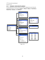
2.3.1 STANDARD RELAY 1, 2, AND 3
Every ST-72 comes standard with three programmable relays that the user can
individually program to suit their needs. This is achieved through the STANDARD
RELAY menus accessed from the ALARM OUTPUTS menu. Only one Standard
Relay menu screen is shown in Figure 2-9 because all the standard relay’s menus are
identical. Under the STANDARD RELAY menu the user can configure the following.
Alarm
Outputs
Standard
Relay
Standard
Relay
1
~
A1
Votes
Required
1
Standard
Relay
2
~
A2
Votes
Required
0
Standard
Relay
3
~
A3
Votes
Required
0
Horn/Piezo
~
Acknowledge
No
Discrete
~
Failsafe
No
~
Zone
Relay
Programmable
Relay
1
Yes
Override 1 Channel
Standard Relay and Programmable
Relay Menus are Identical
0
Figure 2-9
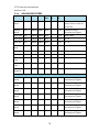
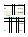
2.3.1.1 A1 A2 & A3 VOTES REQUIRED
A1 Votes Required, A2 Votes Required, & A3 Votes Required are the number
of A1, A2, & A3 level alarms that must be present for the relay to activate. This allows
creation of logical AND function equations that control standard relays. Default settings
for standard relay 1 are A1 Votes = 01 A2 Votes = 00 & A3 Votes = 00 which
causes relay 1 to trip if any channel has an A1 level alarm active. Default settings for
standard relay 2 are A1 Votes = 00 A2 Votes = 01 & A3 Votes = 00 which causes
relay 2 to trip if any channel has an A2 level alarm active. Example: If either default
setting is modified such that A1 Votes = 02 and A2 Votes = 01, then any two
channels must have an A1 level alarm active and any one channel must have an A2 level
alarm active to trip that relay. REMEMBER! One of the A1s and the A2 could be on the
same channel. These level alarms must come from a channel included in the Zone
entry described below.
2.3.1.2 ACKNOWLEDGE
Turning Acknowledge YES allows the standard relay to be deactivated during alarm
conditions by an Alarm Reset. This is useful if an audible device is being driven by the
relay
2.3.1.3 FAILSAFE
Failsafe controls relay activation for this standard relay. Failsafe YES causes the
relay to de-energize during alarm conditions and energize when there is no alarm.
Thereby, a power failure forces the relay contact to the alarm position. Note the
22
ST-72 Controller Users Manual
Revision b 2.0
standard Fault relay is always failsafe and may be monitored separately to indicate loss
of power conditions in many applications.
2.3.1.4 ZONE 1-8
Zones offer additional flexibility by controlling which channel zones trip this menu’s
standard alarm relay. There are eight possible zones that can be assigned to the relays
individually. Some applications have different types of sensors, or sensors in different
areas connected to the same ST-72 Controller. In these cases, it may be undesirable for
a sensor in one area to trip the same relay as a sensor in another area. The Zone
menus may restrict this. For example, channels 1-32 might be set to trip standard relay
1 while channels 33-64 trip standard relay 2. This is done by assigning channels 1-32 to
zone 1 and channels 33-64 to zone 2 and turning only zone 1 to YES for Standard relay
1 and only zone 2 to YES for standard relay 2. Another possibility is channels 1-32 be
set to trip standard relay 1 while channels 33-64 trip relays on an optional discrete relay
PCB configured for Alarm 1 (see section 3.2.2).
2.3.1.5 OVERRIDE CHANNELS 1-8
Override allows entering one of the 256 different alarms that will trip this relay
regardless of the Votes or Zone entries. There are four alarms per channel and 64
channels and any one of these alarms may be used as the Over Ride. This feature is
useful when one channel’s alarm has more significance than the others. Up to eight
override alarms may be entered per relay.
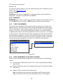
2.3.2 HORN/PIEZO
The ST-72 is equipped with a low decibel audible piezo which chirps when keys are
pressed and may be configured to audibly indicate alarm conditions. The standard horn
relay is similar to the standard A1 & A2 relays.
Alarm
Outputs
Horn/Piezo
Standard
Relay
1
~
Alarm
1
Beep
Standard
Relay
2
~
Alarm
2
On
Standard
Relay
3
~
Alarm
3
On
Horn/Piezo
~
Acknowledge
Discrete
~
Failsafe
No
~
Piezo
No
Relay
Programmable
Relay
Alarm
Yes
Figure 2-10
2.3.2.1 A1 A2 & A3
Alarm 1, Alarm 2, & Alarm 3 menus control how this alarm level from each channel
will affect the standard horn relay. Choices are OFF, ON or BEEP (one Hz. Pulsating).
As an example, A1 conditions might pulse the horn (BEEP) and A2 conditions to cause
a steady horn (ON). Any other combination of these 3 choices is possible for A1, A2,
and A3 levels affecting the horn relay. This feature is very useful since it allows the horn
relay to serve as another level A1, level A2, level A3 or both. Individual channel alarms
23
ST-72 Controller Users Manual
Revision b 2.0
may also be configured to not affect the Horn relay on a channel by channel basis (see
section 2.4.2.5).
2.3.2.2 ACKNOWLEDGE
Turning Acknowledge YES allows the Horn relay to be deactivated during alarm
conditions by an Alarm Reset. This is useful if an audible device is being driven by the
relay
2.3.2.3 FAILSAFE
Failsafe controls relay activation for this relay. Failsafe YES causes the horn relay to
de-energize during alarm conditions and energize when there is no alarm. Thereby, a
power failure forces the relay contact to the alarm position.
2.3.2.4 PIEZO ALARM
Piezo Alarm ON causes the audible piezo to duplicate the action of the horn relay.
This feature may be used to provide a low decibel indication of the status of the
system’s horn.
2.3.3 DISCRETE RELAY
10-00345 Discrete relay options may also be configured to function in a Failsafe mode
using the ALARM OUTPUTS menu shown in Figure 2-11. Entering YES causes these
discrete relays to have energized coils when no alarm condition exists for the associated
channel and de-energized coils when the alarm occurs. Failsafe is useful for indicating
failed relay coils and loss of power conditions.
Alarm
Outputs
Discrete
Relay
Standard
Relay
1
~
A1
Failsafe
No
Standard
Relay
2
~
A2
Failsafe
No
Standard
Relay
3
~
A3
Failsafe
No
Horn/Piezo
~
Discrete
~
Relay
Programmable
Relay
~
Figure 2-11
24
ST-72 Controller Users Manual
Revision b 2.0
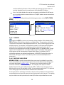
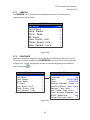
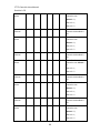
2.3.4 PROGRAMMABLE RELAY
The 10-0350 Programmable relay option board may be added if the user needs sixteen
more programmable relays in addition to the three standard relays. These 16 relays are
configured through the PROGRAMMABLE RELAY menus accessed from the
ALARM OUTPUTS menu show in Figure 2-12. Only one Programmable Relay menu
screen is shown because all the Programmable relay’s menus are identical. Under the
PROGRAMMABLE RELAY menu the user can configure the same parameters as
STANDARD RELAYS discussed in section 2.3.1.
Alarm
Outputs
Programmable
Relay
Brd
Programmable
Relay
Brd
Standard
Relay
1
~
Programmable
Relay
1
~
A1
Votes
Required
1
Standard
Relay
2
~
Programmable
Relay
2
~
A2
Votes
Required
0
Standard
Relay
3
~
Programmable
Relay
3
~
A3
Votes
Required
~
Programmable
Relay
4
~
Acknowledge
~
Programmable
Relay
5
Horn/Piezo
Discrete
Relay
Programmable
Relay
Brd ~
"
"
Programmable
Relay
0
No
~
Failsafe
"
~
Zone
No
16
~
Override 1 Channel
Standard Relay and Programmable
Relay Menus are Identical
1
Yes
0
Figure 2-12
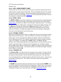
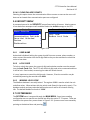
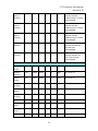
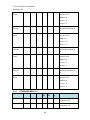
2.4 CHANNEL CONFIGURATION ENTRY MENU
CHANNEL CONFIGURATION is accessed through the MAIN MENU. Once in the
CHANNEL CONFIGURATION entry menu, show on left in Figure 2-13; use
/
to scroll up or down to select the channel that is to be configured. Once the
Edit
correct channel is selected
brings you to that channel’s configuration menu, shown
on right below. These items affect only the specific channel selected. System specific
variables are accessed through the MAIN MENU shown in Figure 2-1.
Channel
Config
Measurment
1 PCTLEL
Name
Measurment
46 PCTLEL
Name
Measurment
6 PCTLEL
Channel
Ch.37
Ch.38
Ch.39
1
~
Alarm
2
~
Alarm
3
~
Fault
Alarm
~
From
~
Linearize
~
Configure
~
Figure 2-13
25
Config
Alarm
Data
Name
38
ST-72 Controller Users Manual
Revision b 2.0
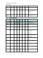
2.4.1 CHANNEL CONFIGURATION MENUS
Once the appropriate channel has been selected its configuration menu allows the
following parameters to be accessed: Alarm 1, Alarm 2, Alarm 3, Fault Alarm,
Data From, Linearize, and Configure.
Ch.
38
Alarm
1
SetPoint
20
Latching
No
Trip
On
On
High
Delay
Off
(sec)
Delay
Horn
0
(min)
0
Drive
Yes
Ch.
Ch.
No
On
(sec)
Delay
Horn
0
(min)
0
Drive
Config
1
~
Alarm
2
~
Alarm
3
~
Fault
Alarm
~
~
Linearize
~
Configure
~
Alarm
2
40
Latching
No
Trip
On
On
High
Delay
Off
(sec)
Delay
Horn
0
(min)
0
Drive
Yes
Color
Red
Yes
Color
Alarm
From
High
Delay
Off
Data
3
Latching
On
38
Alarm
60
Trip
Channel
38
SetPoint
38
SetPoint
Red
Enabled?
No
Ch.
38
Fault
Alarm
SetPoint
Ch.
38
Data
Src
From
Analog
Input
Min
Raw
800
Max
Raw
4000
Filter
Local
Sample
Cal
Marker
-10
Count
Board
10
Default
Menu
~
Ch.
38
Linearize
Input
Output
10.00
10.00
Name
20.00
20.00
Units PCTLEL
30.00
30.00
Zero
0
40.00
40.00
Span
100
50.00
50.00
0
60.00
60.00
Yes
70.00
70.00
1
80.00
80.00
1
90.00
90.00
Ch.
Info
38
Configure
Measurement
Engineering
Decimal
Points
Channel
On?
Zone
Deadband
Copy
To
Copy
To
Restore
(%)
Channel
~
Group
~
Ch.
~
Defaults
Figure 2-14
26
ST-72 Controller Users Manual
Revision b 2.0
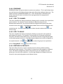
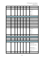
2.4.2 ALARM 1 / ALARM 2 / ALARM 3 MENU
The ALARM MENU parameters are listed only once, because alarms 1, 2, and 3 are
identical except A1 does not have the option to change the color, it is always yellow,
and only A3 can be turned off if not needed. The following parameters can be accessed
while in the ALARM MENUS.
Ch. 38 Alarm 3
Channel 38 Config
Alarm 1
~
Alarm 2
~
Alarm 3
~
Fault Alarm
~
Data From
~
Linearize
~
Configure
~
SetPoint
60
Latching
No
Trip On
High
On Delay (sec)
0
Off Delay (min)
0
Horn Drive
Yes
Color
Red
Enabled?
No
Figure 2-15
2.4.2.1 SETPOINT
SETPOINT is the value where the alarm trips. It is entered in engineering units. For
example, if a channel monitors 0-50 ppmH2S and the alarm must trip at 10 ppm, the
correct entry is 10.00.
2.4.2.2 LATCHING
LATCHING determines either manual or automatic alarm reset operation. YES
requires a manual Alarm Reset to unlatch the alarm even though an alarm condition no
longer exists. YES also causes this alarm group’s common relay, front panel LED, and
optional discrete relay to latch. NO allows all outputs for this alarm to automatically
reset as soon as the alarm condition clears.
2.4.2.3 TRIP ON
TRIP ON is set to HIGH for increasing alarms or LOW for decreasing alarms to
determine if the alarm activates upon exceeding or falling below the setpoint.
2.4.2.4 ON/OFF DELAYS
The ON DELAY / OFF DELAY entries allow ON and OFF time delays affecting how
long the setpoint must be surpassed before an alarm event transition occurs. ON delays
are limited to 10 seconds while OFF delays may be as long as 120 minutes. Delays are
useful in many applications to prevent nuisance alarms and unwanted cycling into and
out of alarm conditions.
2.4.2.5 HORN ON
The HORN ON entry allows linking this alarm to the common horn relay. NO causes
the alarm to have no effect upon the horn relay. Entering YES causes this alarm to
27
ST-72 Controller Users Manual
Revision b 2.0
turn the horn relay on steady, or, to pulse it depending upon horn configuration in the
system menu (see section 2.3.2.1).
2.4.2.6 COLOR
COLOR gives the option of assigning A2 or A3 alarms different colors besides the
default RED. The options are RED BLUE and ORANGE.
2.4.2.7 ENABLED
ENABLED? Alarm 3 only. Because most applications require only two alarm levels, A3
is turned NO (off) from the factory. YES activates the A3 alarm level if needed.
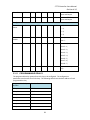
2.4.3 FAULT ALARM MENU
The channel alarm identified as Fault activates when the input is out of range in the
negative direction. The fault level is always low trip and the dedicated common fault
relay is always failsafe. The minimum setting is -10% of full scale. The factory default
setting is -10; which is -10% of 100 or default full scale value. If the full scale value is
changed the fault value is automatically updated to reflect the new value. For example
if the fault level is -10 and the full scale value is changed from 100 to 50 the fault level
will automatically changed to -5 which is -10% of the new full scale value. If the fault
level is -5 (-5% of full scale) and the full scale value is changed from 100 to 50 the fault
level will automatically changed to -2.5 which is -5% of the new full scale value.
Channel 38 Config
Alarm 1
~
Alarm 2
~
Alarm 3
~
Fault Alarm
~
Data From
~
Linearize
~
Configure
~
Ch. 38 Fault Alarm
SetPoint
-10
Figure 2-16
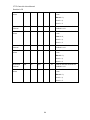
2.4.4 DATA FROM MENU TO SET INPUT SOURCE
Channels may be independently configured to accept input data from the following
sources:
An analog input PCB attached to the I2C bus. These include Analog and Bridge
input boards.
Modbus RS-485 from up to four configured master ports connected to Modbus
slave devices.
Modbus TCP/IP connected to the Ethernet port.
Note: Each Modbus menu selection also requests the RTU # and the Alias
register # location of the data to be retrieved from the RTU. Alias register
28
ST-72 Controller Users Manual
Revision b 2.0
numbers define the location of the variable representing the input value and
must be obtained from the manufacturer of the Modbus RTU device.
One of our Radio Modem kits may be connected to the Modbus RS-485 master
port to enable wireless communication to ST-48/RF wireless sensor transmitters.
See section 7.2.
Channel’s inputs are configured using the following parameters in the DATA FROM
MENU.
Channel
38
Config
Ch.
38
Data
From
Alarm
1
~
Src
Alarm
2
~
Min
Raw
800
Alarm
3
~
Max
Raw
4000
Alarm
~
Filter
~
Local
Linearize
~
Marker
Configure
~
Fault
Data
From
Analog
Sample
Cal
Count
Board
Menu
Input
10
Default
~
Figure 2-17
2.4.4.1 SOURCE
Edit
toggles the SRC or source entry between Analog, Modbus 16bit, Modbus 16bit
Signed, Modbus 32bit, Wireless Monitor, and Digital Input. This parameter tells the ST72 where the information to be displayed comes from. Each 16 channel group can have
multiple sources. For example if an application needs 12 4-20 inputs and 52 Modbus
inputs the first 12 channels can be programmed for Analog input and the last 52
channels can be programmed to accept the Modbus inputs. For Modbus 16bit, a single
register will be interpreted as an unsigned 16bit integer. For Modbus 16bit signed, a
single register will be interpreted as a signed 16bit integer. For Modbus 32bit, 2
consecutive registers are read and interpreted as a 32bit IEEE Floating Point value. In
32bit Mode, the register value is read directly and not scaled with Min/Max Raw
parameters.
2.4.4.2 MIN RAW & MAX RAW
MIN/MAX RAW is the Min Raw and Max Raw counts entries included in Input Data
From: menus define the range of input counts that provide Measurement Range readout values described in section 2.4.6.2. This menu entry is determined by the A/D
converter resolution of the channel’s input. For example, if the input is a 10 bit
Modbus® device with zero at 200 counts and 100% at 1000 counts, then this menu’s
MIN should be set at 200 and MAX at 1000. If communicating with the ST-72’s optional
12 bit Analog Input PCB the MIN should be 800 and the MAX 4000.
If the input device’s resolution is unknown, the live counts variable on the Combination
screen displays actual raw A/D counts currently being read by this channel. This reading
may be used to test the input device for what A/D counts are provided for zero and
29
ST-72 Controller Users Manual
Revision b 2.0
100% if these values are unknown. Forcing the input device to read zero should provide
the A/D counts value needed to make this channel’s display also read zero. Likewise,
forcing the input device to read 100% should provide the A/D counts value needed to
make the ST-72 channel’s display also read 100%.
Note: Each Data From: item has a matching default Min/Max counts value of 20% to
100% with ± 5% over/under range applied. If the default value is incorrect for the input
device it should be edited.
2.4.4.3 FILTER SAMPLE COUNT
The FILTER SAMPLE COUNT is the number of samples from an Analog Input
channel that are averaged together before displayed. The valid range is 1-40 with the
default value of 10. If a channel has a noisy input the sample rate can be increased
causing the noise to average itself out. This higher number of samples causes the
channel to react slower to input.
2.4.4.4 LOCAL CAL
LOCAL CAL is available with the Analog Input option. There are three choices Board
Default, On, and Off. With the Analog Input option used for both the Analog and Bridge
input boards, Board Default automatically turns the local calibration feature On for the
Bridge input and Off for the Analog Input. If there is a need to calibrate a channel locally
and the board default is Off it can be manually changed.
ST-72 CAL MODE features allow pushbutton calibration of zero and span values. This
feature should be utilized only when there are no other zero/span controls within the
monitoring system since it is inappropriate to calibrate a signal at more than one point.
Therefore, if calibration is to be performed at another transmitter or monitoring device,
the ST-72 CAL MODE feature should not be used.
The CALIBRATION MENU allows entering the correct Cal ZERO & Cal SPAN set-point
values needed to calibrate the sensor. These are entered in the same engineering units
as input range. Set Zero & Set Span controls in this menu allow pushbutton
Edit
calibration by moving the highlight bar to each and pressing the
. A live reading of
the channel’s value in the tool tip box allows calibration checks to see if an adjustment is
needed. Unintentional calibrations are reset by the Set Unity Gain menu item. Set
Unity Gain resets zero offset to 0 and span gain to 1. It is useful for returning the
calibration to a known starting place. Sensor aging may be monitored by recording zero
and span readings at Unity Gain when it is new, and again at later dates when
degradation may have occurred.
To check zero calibration, apply the ZERO calibration value to the sensor and observe
the live reading. If the zero reading differs from the zero setpoint, a calibration is
needed. To calibrate zero, move the highlight bar to Set Zero and press
warning message explains that pressing
Edit
Edit
. A
again will change the zero calibration and
30
ST-72 Controller Users Manual
Revision b 2.0
any other key will exit. The procedure for span calibration is identical. For example, if a
gas sensor is to be spanned with 50% span gas, the span set-point must be 50%. If 45%
is to be used later, the span set-point must be changed to 45% to match the span
calibration gas. If the reading is only 40% with the 50% gas applied, a span calibration is
Edit
needed. Move the pointer to the Set Span entry and press
twice. Unity Gain
may be used at anytime to cancel incorrect calibrations and start again.
2.4.4.5 MARKER MENU
Some transmitters or monitoring devices providing ST-72 inputs also indicate special
modes of operation, such as Calibration, Maintenance or Fault, by transmitting a special
<4mA or negative “Marker” value. The ST-72 offers channel Marker menus for
detecting and indicating such events (see Figure 2-18). While active, the ST-72diplays a
6-digit ASCII message to indicate the special event and if equipped with 10-0348 4-20mA
output option, the ST-72 also transmits the same <4mA value.
Ch.
Src
38
Data
From
Wireless
Ch.
Marker
Enabled
Marker
%
Raw
200
Max
Raw
1000
ID
10
Interface
COM1
Marker
Marker
Monitor
Min
Remote
38
Menu
Mark
as
Sensor
Menu
Yes
-16
IN
Life
CAL
Yes
~
Figure 2-18
2.4.4.5.1
Marker Enabled
Turns the marker feature ON and OFF
2.4.4.5.2
Marker %
The negative Marker value is entered into the Marker % field as a negative percent of
full scale. For example, -15.62% of full scale detects a marker value of 1.5mA (1.5mA is 15.62% of full scale when 4-20mA is the range). Marker mode is active when the input
value reads the Marker % +- 1% of full scale.
2.4.4.5.3
Mark As
The Mark As menu allows user entry of the 6-digit ASCII message to be displayed when
the marker is detected.
2.4.4.5.4
Sensor Life
Sensor Life should only be activated when the Marker event is Calibration and when a
sensor life value is transmitted after each calibration. This feature is provided primarily
31
ST-72 Controller Users Manual
Revision b 2.0
for use when interfacing the ST-72 to R. C. Systems’ ST-48 Sensor Transmitters which
may be configured to transmit sensor life values after each calibration (Figure 2-19). For
Sensor Life to record properly the monitor must perform as follows: After the
Calibration Marker interval, 4.0mA transmits for 10 seconds to indicate its calibration
mode is complete. The monitor then transmits between 4.0mA and 5.0mA for five
seconds depending on remaining sensor life where 4.0mA = 0% and 5.0mA = 100%
remaining sensor life. The ST-72 reads this value and records it as the channel’s Sensor
Life. Sensor Life is stored in the ST-72 Modbus database and displayed as a bar-graph in
the Sensor Info screen (see section 2.7.7). It is a useful tool for planning sensor
replacement schedules.
Figure 2-19
2.4.4.6 REMOTE ID
When the Data From is set to receive input through the Communications ports, this is
where the salve’s unique ID number is entered. Remote ID numbers up to 247 are valid.
2.4.4.7 ALIAS
The Alias register numbers define the location of the variable representing the input
value of the Modbus data received through the Communications ports. This number
must be obtained from the manufacturer of the Modbus RTU device.
2.4.4.8 INTERFACE
The Interface assigns what communication port the Modbus slave or Wireless radio is
connected to and the channel will get its data from. The communication port that is
assigned here must be configured as a Modbus Master or Wireless Monitor in the
Communications Menu (see section 2.5.1).
2.4.4.9 SLAVE BYTE ORDER
If Modbus 32 BIT is selected, a Byte Order entry appears at the bottom of the menu.
This determines WORD and BYTE alignment of data at the remote Modbus transmitter
when sending its 4 byte IEEE Floating Point values. With the select bar on this entry, the
Edit
toggles between the 4 possible modes.
32
ST-72 Controller Users Manual
Revision b 2.0
2.4.5 LINEARIZE
The linearization menu allows each channel to have its own linearization curve stored in
the controller’s non-volatile memory. Input versus output points must be entered in
percent of full scale values. This means if the range is 0-200 ppmH2S then 100 ppm is
50% of full scale. Zero input will provide a zero output and 100% input a 100% output.
Nine intermediate points may be entered to define the curve.
38
Linearize
Alarm
1
~
Input
Output
Alarm
2
~
10.00
10.00
Alarm
3
~
20.00
20.00
Fault
Alarm
~
30.00
30.00
~
40.00
40.00
Linearize
~
50.00
50.00
Configure
~
60.00
60.00
70.00
70.00
80.00
80.00
90.00
90.00
Channel
Data
38
Ch.
Config
From
Figure 2-20
2.4.6 CONFIGURE MENU
From the entry level setup menu in Figure 2-14 the CONFIGURE menu may be entered
for setting variables defining how the controller presents monitored data to the various
graphic displays.
Channel 38 Config
Ch. 38 Configure
Alarm 1
~
Info
Alarm 2
~
Engineering Units PCTLEL
Alarm 3
~
Zero
0
Fault Alarm
~
Span
100
Data From
~
Decimal Points
Linearize
~
Channel On?
Configure
~
Zone
1
Deadband (%)
1
Copy To Channel
~
Copy To Group
~
Restore Ch. Defaults
~
Figure 2-21
33
Measurement Name
0
Yes
ST-72 Controller Users Manual
Revision b 2.0
2.4.6.1 INFO / MEASUREMENT NAME
The first two items in this menu are for entering the 16 character Measurement Name
and 6 character engineering unit ASCII fields. Eunits should define the units of measure
for what this channel is to display. Measurement Name should describe the source of
this data in the user’s terminology. Section 2.2 of this manual describes how to use the
front keypad to modify these fields.
2.4.6.2 ZERO / SPAN
The ZERO / SPAN entries allow configuration of the measurement range displayed by
this channel. Measurement Range works along with A/D Counts menus, described in
section 2.4.4.2, to define the range of the input signal’s engineering units. For example,
if a channel’s input is 4-20mA from a transmitter monitoring 0 to 10ppm chlorine, then
the Zero value should equal 0.000 and the Span value equal 10.00. The six ASCII
engineering units previously entered are automatically displayed at the top of each
menu as a reminder. Four digits must appear in this entry so trailing 0’s may appear
here that are not displayed on other data screens.
2.4.6.3 DECIMAL POINTS
Resolution of displayed channel values is configured in this menu by setting the number
digits trailing the decimal point. Values are limited to a maximum of four digits, and a
polarity sign. An auto-ranging feature displays the highest resolution allowed by this
menu’s decimal point entry. For example, if three decimal points are entered, and the
range is 0 to 100ppm, the reading will be 0.000 at 0ppm and 100.0 at 100ppm.
However, this may be undesirable due to the high resolution at zero unless the sensor’s
output is extremely stable. If decimal points are limited to one, the 0ppm reading
becomes 0.0 and the 100ppm reading remains 100.0. Resolution may be limited further
by setting decimal points to 0. In the above example, this would cause 0ppm to display
0 and 100ppm to display 100.
2.4.6.4 CHANNEL ON?
The Channel On? entry determines if this channel is to be utilized. Turning it off will
cause the controller to never process inputs applied to this channel and no alarms will
be tripped or data displayed. Inactive channels will be grayed out on the Main Data
screen and skipped when scrolling through the 30 Minute Trend screens. Channels may
be turned off in groups of 16. This is done in the System Setup menu described in
section 2.7.2.4.
2.4.6.5 ZONE
The ZONE feature allows assigning of channels into up to eight possible ZONES. This
is useful for applications that may need all of alike gases or inputs from a certain area to
be grouped together. Once the channels are assigned to a certain group relays can be
configured to respond to only the channels in this ZONE (see section 2.3.1.4).
34
ST-72 Controller Users Manual
Revision b 2.0
2.4.6.6 DEADBAND
DEADBAND allows forcing low values to continue to read zero. This is useful when there
are small amounts of background gases that cause fluctuating readouts above zero. The
highest amount of deadband allowed is 5%. The 4-20mA output is affected by this
menu item and will remain at 4mA until the input gets above the programmed
deadband level.
2.4.6.7 COPY TO CHANNEL
This menu simplifies the Setup procedure by allowing similar channels to be copied from
one to another. For example, if some channels are identical except for the
Measurement Name entry, one channel could be configured and copied to the other
channels that are the same. Only Measurement Name then must be configured on the
copied channels. Use
more to copy.
Edit
and
/
to select channel numbers and
Edit
once
2.4.6.8 COPY TO GROUP
This menu simplifies the Setup procedure by allowing one channel to be copied to a
whole group of channels. For example, if some groups of 16 channels are identical
except for the Measurement Name entry; one channel could be configured and copied
to the whole group at one time. Only Measurement Name then must be configured on
the copied channels. Use
Edit
point to Copy Now? Press
and
Edit
/
to select the group to be copied then
once more to copy.
2.4.6.9 RESTORE CH. DEFAULTS
This menu allows the user to reset a specific channel to factory defaults without
affecting any other channels. This is useful if a channel must be changed to a different
input. All channel configuration will be reset and the user can configure the new
parameters from the factory defaults. A confirming dialog box will appear before the
channel is reset protecting against an accidental restore.
35
ST-72 Controller Users Manual
Revision b 2.0
2.5 COMMUNICATION SETTINGS MENU
COMMUNICATION SETTINGS menu is accessed through the MAIN MENU. This
menu is used to configure the four possible communication ports. Once in the
COMMUNICATION SETTINGS entry menu, show on left in Figure 2-22; use
/
to scroll up or down to select the communication port that is to be configured.
Edit
Once the correct com port is selected
brings you to that com port’s configuration
menu, shown on right below. Com ports 1-4 have identical menus and are shown only
once.
COM1
Settings
Function
Modbus
Master
BaudRate
9600
Parity
None
Timeout
Poll
(ms)
Delay
Sympathy
Radio
500
(ms)
250
Enabled
No
Setup
~
COM1-4 Menus are Identical
Communication
Settings
ModbusTCP
COM1
Settings
~
Slave
COM2
Settings
~
Master
Timeout(ms)
COM3
Settings
~
Master
Poll
COM4
Settings
~
ModbusTCP
Network
Settings
Settings
Troubleshooting
Byte
Settings
Order
ABCD
500
Delay(ms)250
~
~
~
Network
DHCP
Enabled
Hostname
Yes
Controller1
Address
192.168.0.100
Netmask
255.255.255.0
Gateway
192.168.0.1
Figure 2-22
36
Settings
ST-72 Controller Users Manual
Revision b 2.0
2.5.1 COM 1-4 SETTINGS
The four Modbus RS-485 ports can be individually configured multiple ways using the
following menus.
Communication
Settings
COM1
Settings
COM1
Settings
~
Function
COM2
Settings
~
BaudRate
9600
COM3
Settings
~
Parity
None
COM4
Settings
~
Timeout
~
Poll
~
Sympathy
~
Radio
ModbusTCP
Network
Settings
Settings
Troubleshooting
Modbus
Master
(ms)
Delay
(ms)
Enabled
500
250
No
Setup
~
COM1-4 Menus are Identical
Figure 2-23
2.5.1.1 FUNCTION
The Function parameter allows the communication ports to be set as Modbus Master,
Modbus Slave, Wireless Monitor, Redundant Port, or Disabled.
2.5.1.1.1
Modbus Master
Master mode allows the communication port to poll any device using the Modbus RTU
protocol. This setting is also utilized for Wireless Modbus Master. See section 7.4.
2.5.1.1.2
Modbus Slave
Slave mode allows the communication port to be polled by any Modbus Master device
using the Modbus RTU protocol. This setting is also utilized for Wireless Modbus Slave.
See section 7.3
2.5.1.1.3
Wireless Monitor
This mode is exclusively for wireless communication to our ST-48/RF wireless sensor
transmitters (please visit ST-48/RF). See section 7.2.
2.5.1.1.4
Redundant Port
This setting allows the user to create a redundant port which uses the settings from
another port that is already configured. Redundant mode works with ports configured
as Modbus Master. When configured as a redundant port, the Primary port
communicates until it gets a communication error. The ST-72 then switches to the
redundant port and continues to poll the slave nodes. When communication has
switched to the redundant port the ST-72 trips the Fault relay, beeps, and displays a
warning telling the user there has been a communication error. The user is able to
Ignore the warning for 12 hours or Test the Primary port. Ignoring the problem gives
technicians time to trouble shoot and fix the problem. If the problem is not going to be
fixed, the warning message can be cleared permanently by disabling the redundant
37
ST-72 Controller Users Manual
Revision b 2.0
port. If the user chooses to test the port and it passes, a success message will appear
and the error message will be cleared.
Before a Primary port switches to its redundant port, a scan must fail 3 times. All
channels setup to use the primary port are polled. At the end of the scan, if an error has
occurred on any channel, the error count is incremented. After 3 scans fail, the
redundant port takes over communication. If the redundant port also fails 3 times,
communication is switched back to the primary port. When both ports fail, the ST-72
will continuously switch between primary and redundant port.
Individual channels do not enter COMM ERROR mode unless both primary and
redundant port failures occur.
Manual test can be performed on the redundant or primary port by going into the
redundant port’s com setting menu and selecting TEST REDUNDANT PORT or
TEST PRIMARY PORT. While in this menu the ST-72 also gives the active port on
the screen.
2.5.1.1.5
Disabled
Select Disable to turn the port off if not needed.
2.5.1.2 BAUDRATE
This setting allows user to set the data rate of the communication port. The options
include 9600, 19200, 38400, 57600, and 115200.
2.5.1.3 PARITY
A PARITY bit is a bit that is added to ensure that the number of bits with the
value one in a set of bits is even or odd. Parity bits are used as the simplest form of error
detecting code. The default is None.
2.5.1.4 TIMEOUT
The Master TIMEOUT menu item affects the ST-72’s master Modbus ports.
TIMEOUT is the length of time in milliseconds the controller waits before a Modbus
request fails. Three consecutive failed requests must occur before a communication
error is indicated. This item is useful for optimizing throughput to the ST-72 from other
slave RTUs.
2.5.1.5 POLL DELAY
The time in milliseconds the unit will delay between Modbus master requests.
2.5.1.6 SYMPATHY ENABLED
The sympathy feature allows multiple ST-90 Quad controllers, communicating on the
same communication port, to go into an alarm condition simultaneously when any one
ST-90 controller detects an alarm condition. If SYMPATHY ENABLED is set to YES then
the ST-72 controller, which is the master in the network, broadcasts alarm flags to all ST90s in the network. ST-90 controllers that are configured to react to these flags then
energize their relays configured to trip for that alarm. The following sympathy
parameters only show up if sympathy is set to YES.
38
ST-72 Controller Users Manual
Revision b 2.0
2.5.1.6.1
FAULT TRANSMIT
When set to YES the ST-72 broadcasts the Fault alarm flag out of the communication
port. This option is only available if SYMPATHY ENABLED is set to YES.
2.5.1.6.2
A1 TRANSMIT
When set to YES the ST-72 broadcasts the alarm 1 alarm flag out of the communication
port. This option is only available if SYMPATHY ENABLED is set to YES.
2.5.1.6.3
A2 TRANSMIT
When set to YES the ST-72 t broadcasts the alarm 2 alarm flag out of the communication
port. This option is only available if SYMPATHY ENABLED is set to YES.
2.5.1.6.4
SYMPATHY A2 ACK
When set to YES the ST-72 broadcasts the alarm acknowledge flag to acknowledge all
ST-90 relays on the network configured to be acknowledgeable. This option is only
available if SYMPATHY ENABLED is set to YES.
2.5.1.6.5
A3 TRANSMIT
When set to YES the ST-72 broadcasts the alarm 3 alarm flag out of the communication
port. This option is only available if SYMPATHY ENABLED is set to YES.
2.5.1.7 RADIO SETUP
RADIO SETUP is used to configure radio kits that are connected directly to the ST-72.
See section 7.1.
2.5.1.8 SLAVE BYTE ORDER
If Modbus Slave is selected, a BYTE ODER entry appears in the menu. This
determines WORD and BYTE alignment of data at the remote Modbus transmitter when
sending its 4 byte IEEE Floating Point values. With the select bar on this entry, the
toggles between the 4 possible modes. Min / Max Raw values are not used in this
mode.
Edit
2.5.1.9 WIRELESS TIMEOUT
If Wireless Monitor is selected, a WIRELESS TIMEOUT entry appears in the menu.
Edit
The
toggles between 1m, 6m, 12m, and 18m. These represent the number of
minutes the ST-72 will wait before going into COMM. ERROR. See section 7.2.1.
39
ST-72 Controller Users Manual
Revision b 2.0
2.5.2
MODBUS TCP SETTINGS
Communication
Settings
ModbusTCP
COM1
Settings
~
Slave
COM2
Settings
~
Master
Timeout(ms)
COM3
Settings
~
Master
Poll
COM4
Settings
~
ModbusTCP
Network
Settings
Settings
Troubleshooting
Byte
Settings
Order
ABCD
500
Delay(ms)250
~
~
~
Figure 2-24
2.5.2.1 SLAVE BYTE ORDER
If Modbus Slave is selected, a BYTE ODER entry appears in the menu. This
determines WORD and BYTE alignment of data at the remote Modbus transmitter when
sending its 4 byte IEEE Floating Point values. With the select bar on this entry, the
toggles between the 4 possible modes. Min / Max Raw values are not used in this
mode.
Edit
2.5.2.2 MASTER TIMEOUT
The time in milliseconds before the unit gives up on a Modbus request and moves on to
the next channel. After three consecutive timeouts, the channel enters the COM Error
state.
2.5.2.3 MASTER POLL DELAY
The time in milliseconds the unit will delay between Modbus master requests.
2.5.3 NETWORK SETTINGS
See section 10 for integrating a ST-72 into an Ethernet network.
Communication
Settings
Network
Settings
COM1
Settings
~
DHCP
COM2
Settings
~
Hostname
COM3
Settings
~
Address
192.168.0.100
COM4
Settings
~
Netmask
255.255.255.0
~
Gateway
192.168.0.1
ModbusTCP
Network
Settings
Settings
Troubleshooting
~
~
Figure 2-25
40
Enabled
Yes
Controller1
ST-72 Controller Users Manual
Revision b 2.0
2.5.3.1 DHCP ENABLED
Enable this parameter to allow the IP address to be set automatically by an external
DHCP server. When this parameter is enabled, the unit can be accessed by its hostname
or IP address, although the IP address will be dependent on the DHCP server and could
potentially change.
2.5.3.2 HOSTNAME
Hostname identifies the unit on a network as an alternative to the IP address.
2.5.3.3 IP ADDRESS
IP address identifies the unit on a network. This is automatically set when DHCP is
enabled.
2.5.3.4 NETMASK
Specify if your network requires. Netmask specifies the subnet addressing scheme. This
is automatically set when DHCP is enabled.
2.5.3.5 GATEWAY
Gateway is the IP address of the device that may connect this subnet to other networks.
This is automatically set when DHCP is enabled.
2.5.4 TROUBLESHOOTING
The TROUBLESHOOTING option in the communication settings menu can prove to be
very helpful when setting up communications through the ST-72’s numerous
communication ports. This feature allows the user to see how many messages were
either corrupt when received or not received at all.
Communication Settings
Troubleshooting
COM1 Settings
~
View comm failures
~
COM2 Settings
~
Clear failure counts
~
COM3 Settings
~
COM4 Settings
~
ModbusTCP Settings
~
Network Settings
~
Troubleshooting
~
Figure 2-26
41
ST-72 Controller Users Manual
Revision b 2.0
2.5.4.1 VIEW COMM FAILURES
When VIEW COMM FAILURES is selected the screen in Figure 2-27 is shown. Each
individual channel is shown and it is color coded by the communication port that it is
configured for in its own Data From menu (see section 2.4.4). If the channel is not
configured to receive data from a communication port it is shown in grey.
Communication port 1 is shown in cyan (Ch.1-11), communication port 2 in orange
(Ch.12-20), communication port 3 in magenta (Ch.21-31), communication port 4 in blue
(Ch. 33-41), and the Ethernet port in yellow (Ch. 42-47). The number that is shown after
the channel number represents the number of times a query was sent out and either a
corrupt message was received or no message was received at all. When trouble
shooting a specific channel or communication port a simple test can be ran by resetting
this number (see section 2.5.4.2) and then recording the number of communication
failures received after a known amount of time has passes. Make a change to the
system and then repeat the test for the same amount of time. Compare the results to
see if the change has helped the problem.
Ch.01:4
Ch.17:0
Ch.33:1067
Ch.49
Ch.02:6
Ch.18:0
Ch.34:0
Ch.50
Ch.03:7
Ch.19:0
Ch.35:0
Ch.51
Ch.04:2
Ch.20:0
Ch.36:0
Ch.52
Ch.05:4
Ch.21:213
Ch.37:0
Ch.53
Ch.06:3
Ch.22:200
Ch.38:0
Ch.54
Ch.07:6
Ch.23:215
Ch.39:0
Ch.55
Ch.08:7
Ch.24:204
Ch.40:0
Ch.56
Ch.09:5
Ch.25:210
Ch.41:0
Ch.57
Ch.10:3
Ch.26:209
Ch.42:658
Ch.58
Ch.11:4
Ch.27:218
Ch.43:700
Ch.59
Ch.12:0
Ch.28:216
Ch.44:668
Ch.60
Ch.13:0
Ch.29:211
Ch.45:687
Ch.61
Ch.14:0
Ch.30:204
Ch.46:698
Ch.62
Ch.15:0
Ch.31:207
Ch.47:690
Ch.63
Ch.16:0
Ch.32
Ch.48
Ch.64
Comm Port 1
Comm Port 2
Comm Port 3
Cyan
Orange
Magenta
Comm Port 4
Ethernet Port
Channel Off
Figure 2-27
42
Blue
Yellow
Grey
ST-72 Controller Users Manual
Revision b 2.0
2.5.4.2 CLEAR FAILURE COUNTS
Selecting this option clears the communication failure counter so test can be run or old
data can be cleared after communication ports are configured.
2.6 SECURITY MENU
A password entered in the SECURITY menu allows locking all menus. Viewing menus
is not denied but attempts to edit variables flashes the Locked message on the LCD.
Main
Alarm
Menu
Outputs
Channel
Config
Communication
Security:
Security:
~
User
Name
~
Lock
Code
Settings ~
Unlocked
Modbus
Lock
Unlocked
Default
User
Code
0
~
System
~
Diagnostics
~
Figure 2-28
2.6.1 USER NAME
Authorized individuals locking the system should first enter a name, phone number, or
other contact information into the 10 digit field so they can be contacted to unlock the
unit at a later date.
2.6.2 LOCK CODE
To lock or unlock the system the correct 4 digit authorization number must be entered
into the Lock Code field. The ST-72 will ask this 4 digit code to be re-entered and then
it will be lock. Once locked, re-entering the code will unlock the unit.
It is very important to record the 4 digit code. However, if lost the controller may be
unlocked by entering the override code: 8621
2.6.3 MODBUS LOCK CODE
The Modbus database is normally locked. The register 40099 is used to unlock the unit
and allow writes. When written with the unlock code (found in the security menu). The
database unlocks and stays unlocked while writes occur and for 10 minutes of being
idle. The default Modbus lock code is “1234”.
2.7 SYSTEM MENU
The SYSTEM menu is accessed through the MAIN MENU. Some items needing
configuration are not specific to a channel but affect the entire ST-72 system. These are
located in the system entry menu shown in Figure 2-29. System menus are accessed by
pointing to the desired item and pressing
Edit
43
.
ST-72 Controller Users Manual
Revision b 2.0
Configure
Name
Controller
Contrast
Date
10/20/2010
Time
09:43:28
Enable
Channel
Display
Warmup
Cal
Time
Screen
Block
Negative
Relay
Refresh
0
Names
Tank
Farm
Zone
3
West
Gate
Zone
4
Switchgear
Room
Zone
5
Control
Room
Zone
6
Main
Zone
7
Zone
7
Zone
8
Zone
8
~
Card
Status
~
Logger
Log
~
Save
Config
File
~
Life
~
Load
Config
File
~
View
Log
v1.00
~
Names
~
Mimic
Mode
~
Card
Sensor
Yes
(min)
2
Zone
View
1
Enabled Yes
1
Configure
Event
1
(min)
Zone
Version
Clear
Data
Zone
System
Event
Main
(min)
Zone
View
Count 64
Alarm
Time
Purge
Zone
SD
1
50
Log
North
SD
Entrance
Mimic
Process
Mimic
Mode
Mode
Enabled
Configure
Slave
No
COM1
ID
1
Card
OK
Enabled
File
YES
Trend
~
Time
Date
Event
09:42
07/13/2010
Alarm
1
out
Ch.
19
09:30
07/13/2010
Alarm
Reset
19
09:28
07/13/2010
Alarm
1
08:15
07/13/2010
System
21:37
07/12/2010
Alarm
21:35
07/12/2010
Alarm
21:30
07/12/2010
Alarm
21:28
07/12/2010
Alarm
17:56
07/09/2010
Comm
15:53
07/02/2010
Config
11:15
06/12/2010
Cold
09:37
06/01/2010
Cal
out
46
09:30
06/01/2010
Cal
in
46
05:36
05/24/2010
Fault
out
32
Version
05:35
05/24/2010
Fault
in
32
Configure
in
19
Boot
--
1
out
07
2
out
07
2
in
07
1
in
07
Error
16
Error
Boot
22
--
System
SD
Measurement
%
Oxygen
Measurement
%
Measurement
Measurement
Measurement
Measurement
Measurement
Measurement
Measurement
Measurement
Measurement
ppm
H2S
Measurement
Measurement
Measurement
Measurement
Measurement
Measurement
Measurement
Measurement
Measurement
Measurement
Measurement
Measurement
Measurement
Measurement
Measurement
Measurement
Measurement
Measurement
Measurement
Measurement
Measurement
%
Oxygen
Measurement
Measurement
Measurement
%
Oxygen
Measurement
Ppm
%
Oxygen
Measurement
Measurement
Measurement
Measurement
Measurement
Measurement
%
Oxygen
Measurement
Measurement
Measurement
Measurement
Measurement
Measurement
Measurement
Measurement
Measurement
Measurement
Measurement
Ch.
Ch.
Measurement
H2S
32
off
48
off
Figure 2-29
44
Oxygen
V1.00
Are you sure you want
clearNames
the event log?
Zone
Card
Yes (Edit)
No
View Event Log
Clear Event Log
to
(Next)
~
~
~
~
~
ST-72 Controller Users Manual
Revision b 2.0
2.7.1 VERSION
The VERSION line in the System menu displays the version of firmware that is
programmed in the controller.
System
Version
v1.00
Configure
~
Zone
Names
~
Mimic
Mode
~
SD
Card
View
Clear
View
~
Event
Log
Event
Sensor
~
Log
~
Life
~
Figure 2-30
2.7.2 CONFIGURE
Some items needing configuration are not specific to a channel but affect the entire ST72 system. These are located in the CONFIGURE entry menu shown on the right side
of Figure 2-31. System Configuration menus are accessed by pointing to the desired
Edit
item and pressing
.
System
Version
Configure
v1.00
Name
Unit-72-3967
Configure
~
Contrast
Zone
Names
~
Date
10/20/2010
Mimic
Mode
~
Time
09:43:28
~
Enable
~
Display
Log
~
Warmup
Life
~
Cal
SD
Card
View
Clear
View
Event
Event
Sensor
Log
Figure 2-31
45
Channel
Alarm
Time
Purge
Zone
50
Data
(min)
Time
Screen
Count 64
Main
(min)
1
1
Enabled Yes
Block
Negative
Relay
Refresh
Yes
(min)
0
ST-72 Controller Users Manual
Revision b 2.0
2.7.2.1 NAME
Assign the controller a name for use in the backup configuration file name on the SD
card. The controller name is limited to 16 characters.
2.7.2.2 CONTRAST
The Configure menu item identified as CONTRAST allows users to adjust the LCD
contrast to a level suitable to the ambient lighting. Selecting CONTRAST and pressing
Edit
causes the
/
keys to increase and decrease LCD contrast.
2.7.2.3 DATE & TIME
Adjust the date and time here for use in DATA and EVENT LOGGING. This is a factory
setting but may need to be adjusted for the end users location.
2.7.2.4 ENABLE CHANNEL COUNT
For applications that do not need 64 channels, the ST-72 can be configured to display
16, 32, or 48. With fewer channels to be displayed in MAIN DATA screen the cells
expand for better resolution.
2.7.2.5 DISPLAY ALARM
Utilizing the display alarm feature in the System menu allows the ST-72 controller to
force the LCD to the MAIN DATA or ZONE screens when an alarm level is reached. This
proves to be useful if channel or zone must be displayed when in alarm. The MAIN
DATA screen is the default alarm screen from the factory.
2.7.2.6 WARMUP & CAL PURGE TIME
WARMUP & CAL PURGE TIME are available to prevent unwanted alarm trips
during these times. This time can be adjusted up to five minutes for sensors that take a
long time to warmup or drift back down after a calibration.
2.7.2.7 ZONE SCREEN ENABLED
In some applications all points are linked together in one large ZONE so the ZONE screen
does not need to be displayed. Turning ZONE SCREEN ENABLED to NO causes
scrolling through the screens to skip the ZONE screen.
2.7.2.8 BLOCK NEGATIVE
This setting prevents negative channel values from being displayed. It applies to all
channels.
2.7.2.9 RELAY REFRESH
RELAY REFRESH menu allows reactivation of Acknowledged alarms after the time period
expires. This feature is used primarily to restart audible alarm devices after having been
silenced by an acknowledge function (via serial port or pressing the Alarm Reset button).
An entry of 0 seconds effectively disables the Alarm Refresh function. Maximum of 60
minutes allowed.
46
ST-72 Controller Users Manual
Revision b 2.0
2.7.3 ZONE NAMES
ZONES 1-8 names can be edited for a quick reference while in the zone screen. These
16 character names show up in the title bar of each zone.
System
Version
Zone
Names
v1.00
Zone
1
Configure
~
Zone
2
Tank
Farm
Zone
Names
~
Zone
3
West
Gate
Mimic
Mode
~
Zone
4
Switchgear
Room
~
Zone
5
Control
Room
~
Zone
6
Main
Log
~
Zone
7
Zone
7
Life
~
Zone
8
Zone
8
SD
Card
View
Event
Clear
View
Log
Event
Sensor
North
Entrance
Process
Figure 2-32
2.7.4 MIMIC MODE
When mimic mode is enabled, the ST-72 will duplicate the data and alarms of another
ST-72 which can be connected with RS485 or TCP/IP. Entering the communications port
and slave ID allows the ST-72 to automatically retrieve programmed configuration
parameters from the Main controller. The Mimic controller’s communication port must
be configured as the Modbus Master and the Main controller’s communication port is
set to Modbus Slave. Once connected the Mimic controller will update automatically
one minute after any parameter is changed in the Main controller. Alarm Reset from
either controller will acknowledge any relay set to Acknowledge YES (see section
2.3.1.2).
System
Version
Mimic
v1.00
Mimic
Mode
Configure
~
Configure
Zone
Names
~
Slave
Mimic
Mode
~
SD
Card
View
Clear
View
Event
Event
Sensor
~
Log
~
Log
~
Life
~
Figure 2-33
47
ID
Mode
Enabled
No
COM1
1
ST-72 Controller Users Manual
Revision b 2.0
2.7.5 SD CARD
A two gigabyte SD card comes standard with each ST-72. This SD card is not needed for
normal operation, but is useful for data logging and backing up configuration.
When the data logger is enabled, every ten minutes the Min, Max, Average, Alarm 1/2/3
status, Fault status, Calibration status, and Alarm reset for each active channel is written
to the SD card in one minute intervals. The log files are stored on the SD card by date.
Each day a new file is created and stored in a directory structure as follows:
UNIT_NAME\YEAR\MONTH\DAY.csv. The files are comma delimited text files and
work with MS Excel, which can be used to create historical plots of the data.
The first line in the file contains a date stamp. The next line is the header. The header
shows the name of each column. The AVG fields in the header list the zero and span
values for that channel. The zero and span can be used when creating plots. Another
line exists for each minute of the day. Those lines are time stamped with the hour and
minute.
The numeric format of the MIN, MAX, and AVG values are based on channel settings.
The decimal precision is the same that is viewed from the unit. This can be adjusted
with the decimal points parameter in each channel’s Configure menu.
The SD Card can store more than 1 year of historical data, but backups of the card
should be performed on occasion. Backing up logs requires removing the SD card and
inserting it in a PC that has a card reader interface.
System
Version
SD
v1.00
Card
Configure
~
Logger
Zone
Names
~
Save
Mimic
Mode
~
~
SD
Card
View
Clear
View
Event
Event
Sensor
Log
Card
Status
OK
Enabled
YES
Config
File
~
Load
Config
File
~
View
Log
File
Trend
~
Log
~
Life
~
Figure 2-34
2.7.5.1 CARD STATUS
When the SD card is properly inserted into the card slot CARD STATUS will display
OK. If the SD card is removed or becomes corrupt the green LED (Figure1-1) will blink
continuously and CARD STATUS will say CARD NOT FOUND.
48
~
ST-72 Controller Users Manual
Revision b 2.0
2.7.5.2 LOGGER ENABLED
Enabling the Data Logger allows the ST-72 to record the channel data for all active
channels.
2.7.5.3 SAVE CONFIGURATION FILE
By selecting SAVE CONFIG FILE the current configuration file will be backed up on
the SD card. This can be beneficial in the event of a board failure or if multiple ST-72s
must be programmed the same. The filename of the saved will be
UniteNameDDMMYY.cfg where DDMMYY is the current date. Saving configuration will
overwrite previous saves from the same date. It is recommended to backup
configuration once a unit is fully configured.
2.7.5.4 LOAD CONFIGURATION FILE
Once a file is backed up on the SD card it can be loaded back into the ST-72 to change
the current configuration to a previous configuration or the SD card can be moved to
another unit and the configuration can be copied to the second unit. This is done by
selecting LOAD CONFIG FILE then select the name and date of the configuration file
that is to be copied.
2.7.5.5 VIEW LOG FILE TREND
VIEW LOG FILE TREND displays historic 24 hours of data using the 24 Hour Trend
screen format shown in Figure 1-3. The user selects the date to be displayed and all
active channels for that day are loaded into the ST-72. Use the
/
to scroll
through the 64 channels of Historic data. The ST-72 24 Hour Historic Trend data screen
is identified by the cyan background color in the graph area. All alarm processing is
active during viewing of historic trend and if a new alarm becomes present a prompt will
ask the user if they would like to continue viewing the historic data or exit this mode
and view real time readings.
49
ST-72 Controller Users Manual
Revision b 2.0
2.7.6 VIEW EVENT LOG
The ST-72 logs the last 2000 events, first in first out, in non-volatile memory so a SD card
is NOT necessary to view the event log. The events are time and date stamped and if
channel specific the number is shown in the right column. Use
through the events.
/
to scroll
The following events are logged: Alarm 1 In, Alarm 1 Out, Alarm 2 In, Alarm 2 Out, Alarm
3 In, Alarm 3 Out, Fault In, Fault Out, Comm Error, Config Error, IO Error, Cal In, Cal Out,
System Boot, Cold Boot, Alarm Reset, Remote Alarm Reset, Alarm Refresh, Marker,
Configuration Change, and Event Log Cleared.
System
Time
Date
Event
Ch.
v1.00
09:42
07/13/2010
Alarm 1 out
19
~
09:30
07/13/2010
Alarm Reset
19
~
09:28
07/13/2010
Alarm 1 in
19
Mimic Mode
~
08:15
07/13/2010
System Boot
--
SD Card
~
21:37
07/12/2010
Alarm 1 out
07
View Event Log
~
21:35
07/12/2010
Alarm 2 out
07
Clear Event Log
~
21:30
07/12/2010
Alarm 2 in
07
View Sensor Life
~
21:28
07/12/2010
Alarm 1 in
07
17:56
07/09/2010
Comm Error
16
15:53
07/02/2010
Config Error
22
11:15
06/12/2010
Cold Boot
--
09:37
06/01/2010
Cal out
46
09:30
06/01/2010
Cal in
46
05:36
05/24/2010
Fault out
32
05:35
05/24/2010
Fault in
32
Version
Configure
Zone Names
Figure 2-35
50
ST-72 Controller Users Manual
Revision b 2.0
2.7.7 CLEAR EVENT LOG
After initial setup and testing of the controller, CLEAR EVENT LOG is used to
manually clear all events in the log file. If the event log is not cleared the older events
will be pushed out as new ones occur.
System
System
Version
Version
v1.00
V1.00
Configure
Configure
~
Zone Names
~
Are you sure you want to
clearNames
the event log?
Zone
Mimic Mode
~
SD Card
Yes (Edit)
SD Card
~
View Event Log
~
View Event Log
Clear Event Log
Clear Event Log
~
View Sensor Life
~
No (Next)
2.7.8 VIEW SENSOR LIFE
Sensor Life is available when at least one channel has Sensor Life activated in the
Marker menu (see section 2.4.4.5). The Sensor Info screen displays each channel’s
sensor status as illustrated in Figure 2-37. Channels with Sensor Life disabled are
indicate by Ch. # Disabled below the bar. Cal Required indicates no Calibration
Marker value has been received by the ST-72.
System
Measurement
%
Oxygen
Measurement
%
v1.00
Measurement
Measurement
Measurement
Measurement
Configure
~
Measurement
Measurement
Measurement
Measurement
Zone
Names
~
Measurement
ppm
H2S
Measurement
Measurement
Mimic
Mode
~
Measurement
Measurement
Measurement
Measurement
~
Measurement
Measurement
Measurement
Measurement
Measurement
Measurement
Measurement
Measurement
Measurement
Measurement
Measurement
Measurement
Measurement
Measurement
Measurement
%
Oxygen
Measurement
Measurement
Measurement
%
Oxygen
Measurement
Ppm
%
Oxygen
Measurement
Measurement
Measurement
Measurement
Measurement
Measurement
%
Oxygen
Measurement
Measurement
Measurement
Measurement
Measurement
Measurement
Measurement
Measurement
Measurement
Measurement
Measurement
Ch.
Ch.
Measurement
SD
Card
View
Clear
View
Event
Event
Sensor
Log
~
Log
~
Life
~
Figure 2-37
51
H2S
32
off
48
off
~
~
~
~
Figure 2-36
Version
~
Oxygen
ST-72 Controller Users Manual
Revision b 2.0
SECTION 3 INPUT/OUTPUT BOARDS
3.1 MAIN I/O INTERFACE BOARD # 10-0331
!
!
The most basic ST-72 Controller requires only the I/O Board shown in Figure 3-1 for
interfacing to field wiring. The ST-72 primary power supply is applied to terminals 1 &
3(+) and 5 & 7(-) of TB4. This may be from 10 – 30 VDC. WARNING! HIGH VOLTAGES
SUCH AS 115 VAC APPLIED TO THESE TERMINALS MAY CAUSE SEVERE DAMAGE! DC
output terminals 2 & 4(+) and 6 & 8(-) on TB4 provide up to 500mA of fused output
power for powering remote devices such as lamps, transmitters etc.
This Board includes two RS-485 ports that can be independently configured either
master or slave, one Ethernet port, five Standard SPDT 5A relays, consisting of one
dedicated HORN and FAULT relay plus 3 programmable alarm relays, and power supply
I/O terminals. The Ethernet port allows the unit to be a ModbusTCP Master and Slave
and also provides access to the embedded webpage. The failsafe Fault circuit detects
firmware and CPU failures along with transmitter failures. JP1 allows the RS-485 ports
to be configured for 2 or 4 wire operation. A 40 pin ribbon cable connects the I/O Board
to the ST-72 CPU and Display nest assembly. Two I2C bus connectors allow addition of
optional functions such as analog I/O and discrete alarm relays for each channel.
Horizontal jumpers installed in position 1 at JP1 connect the RS-485 port’s RX & TX lines,
simplifying 2 wire daisy chains by providing additional terminals for incoming and
outgoing cables. For example, installing the two COM 1 jumpers connects screw
terminals 1 & 5 and terminals 3 & 7 at TB3. RS-485 terminating resistors R5 (COM 1)
and R11 (COM 2) are located on the MAIN I/O Board and installed by moving the
jumpers at JP2 to position 1. These resistors should not be installed if the port is not at
the end of the communication line.
TB1 of the Main I/O Board allows the ST-72 to be acknowledged remotely. A low signal
at this input will simulate an Alarm Reset event (see section 2.3.1.2). The ‘+’ input of
TB1 is pulled up to +5V. An external circuit or relay can pull the ‘+’ input low (to the ‘-‘
input) to activate the Alarm Reset event. The wiring to the external circuitry should be
no longer than 10 feet.
An optional Auxiliary Standard Relay piggyback Board (part # 10-0332) may be added to
the I/O Board via ribbon cable J3. This option adds another five SPDT 5A relays that
mimic the five standard relays. Auxiliary Standard Relay contacts are available at TB1 on
the optional 10-0332 shown in Figure 3-1.
An optional RS-485 Isolated piggyback Board (part # 10-0368) may be added to the I/O
Board via ribbon cable J5. This option adds two additional isolated RS-485 ports for a
total of four. These two additional serial ports can also be configured for either Master
or Slave. Horizontal jumpers installed in position 1 at JP2 & JP3 (com port 3) and JP5 &
JP6 (com port 4) connects the RS-485 port’s RX & TX lines, simplifying 2 wire daisy chains
by providing additional terminals for incoming and outgoing cables. For example,
installing the two COM 1 jumpers connects screw terminals 1 & 5 and terminals 3 & 7 at
52
ST-72 Controller Users Manual
Revision b 2.0
TB1. RS-485 terminating resistors are installed by moving the jumpers at JP1 (com port
3) and JP4 (com port 4) to position 1. These resistors should not be installed if the port
is not at the end of the communication line.
TB1 allowes
external Alarm
Reset contacts.
J9 is 40 pin ribbon to main
controller.
J5 Ribbon connector
to optional IS PCB.
Ethernet Port
J1 & J2 connect to I2C optional
I/O.
J3 Ribbon connector
to optional AR PCB.
Fuses DC OUT power to
option boards that require 24
VDC. ( 2A 5x20m)
Apply only nominal 24 VDC
(min 10 VDC, max 30 VDC)
power to terminals 1,3
+24VDC & 5,7 -24VDC
(COM) of TB4.
TB4 terminals 2,4 +24VDC &
6,8 -24VDC (COM) provide
Fused 24 VDC power to ST-72
option boards requiring such
power.
Figure 3-1
Main I/O Board
3.2 INPUT / OUTPUT OPTION BOARDS
Telephone style RJ11 connections (J3 and J4 on all option Boards) are used to add
optional 16 channel analog and digital I/O. All option Boards must have 24 VDC applied
to TB3 or TB4 which are tied together making daisy chaining the 24 VDC from one
option board to another possible. All I/O options except the Programmable Relay Board
have LEDs to indicate which channel and alarm they are assigned to. The Programmable
Relay is not limited to groups of 16 channels like the other options so the LEDs are not
required. The connected I/O screen in the Diagnostics Menu is also useful for displaying
and programming the connected I/O Boards.
53
ST-72 Controller Users Manual
Revision b 2.0
3.2.1
OPTIONAL ANALOG INPUT BOARD # 10-0334
!
In compliance with CSA C22.2 No. 152 certification, the 4-20 ma
input does not include or imply approval of the LEL gas detection apparatus
such as sensors, transmitters, or devices connected to the system. In order to
maintain CSA Certification of the system, all 4-20 ma gas detection
instruments connected to the input must also be CSA Certified.
Many transmitters or sensors have analog output signals and the 12 bit Analog Input
Board, shown in Figure 3-2, is available to accept these. TB1 and TB2 with 24 positions
each, offers 3 terminals per channel for distributing power and receiving analog inputs.
These are EXC and HI / LO inputs. TB3 and TB4 with only two positions each, is for daisy
chaining the power supply from one option board to another. When the transmitters
are hi power three wire units it is recommended this power be supplied to each option
board with its own pair of wires connected directly to the DC power supply. Precision
150 ohm 5 watt resistors (R1 – R16) between each channel’s IN LO and IN HI terminals
are termination resistors for 4-20mA inputs.
EXC and IN LO terminals are bussed together internally. EXC terminals are tied directly
to TB3 and TB4 +24 VDC and IN LO terminals are tied to TB3 and TB4 power supply
common. Bussing allows transmitter power to be brought into the system at a single
point (TB3 or TB4) and distributed back out at each channel’s EXC / IN LO terminals to
simplify field wiring. Figure 3-2 includes typical wiring to 2 & 3 wire 4-20mA
transmitters.
54
ST-72 Controller Users Manual
Revision b 2.0
LEDs indicate board
configuration.
Ch.01-16
Ch.17-32
Ch.33-48
Ch.49-64
D3
D4
D5
D6
J3
AI
D1
Status
J3 & J4 are interchangeable
I2C connectors used to add
option PCB assemblies to
the ST-72
J4
J2
PGM
EXC HI LO EXC HI LO EXC HI LO EXC HI LO EXC HI LO EXC HI LO EXC HI LO EXC HI LO
EXC HI LO EXC HI LO EXC HI LO EXC HI LO EXC HI LO EXC HI LO EXC HI LO EXC HI LO
EXC HI LO
01/17
33/49
09/25
41/57
02/18
34/50
10/26
42/58
11/27
43/59
03/19
35/51
R4
R3
R2 R1
R9
R10 R11 R12
04/20
36/52
12/28
44/60
05/21
37/53
13/29
45/61
06/22
38/54
14/30
46/62
07/23
39/55
15/31
47/63
08/24
40/56
16/32
48/64
R6
Rev E
R5
R7
EXC HI LO EXC HI LO EXC HI LO EXC HI LO EXC HI LO EXC HI LO EXC HI LO EXC HI LO
EXC HI LO
TB2
TB4
TB3
J1
24VDC
EXC HI LO EXC HI LO EXC HI LO EXC HI LO EXC HI LO EXC HI LO EXC HI LO EXC HI LO
24VDC Power
For External Device
TB1
+ -
Plus (+) Signal
Input
24VDC
+ -
Power Supply
Common
TB3 & TB4 24VDC inputs
are tied together making
daisy chaining the options
easier, and is the bulk power
for transmitter. EXC+ is
wired internally to channel
"EXC's" and EXC- (COM)
to channel "LO's".
R8 R16 R15 R13 R14
ST-72 Analog Input Board
0010-1260 ASSY: 10-0344
R1-R16 are 150 ohm terminating
resistors for 4-20ma inputs.
EXC
HI
LO
EXC
HI
LO
+PWR
SIG
NC
+PWR
SIG
COM
2 Wire 4-20 mA
Transmitter
3 Wire 4-20 mA
Transmitter
Figure 3-2
55
ST-72 Controller Users Manual
Revision b 2.0
3.2.2 OPTIONAL DISCRETE RELAY BOARD # 10-0345
An optional Discrete Relay Board, shown in Figure 3-3, adds sixteen 5 amp (resistive)
form C relays per sixteen channel alarm board. Each BOARD may be configured via
Diagnostics Menu in the ST-72 for ALARM 1, ALARM 2, ALARM 3 or FAULT for channels
1-16, 17-32, 33-48 or 49-64. Each relay has a LED associated with it indicating whether
the relay is energized. An illuminated LED indicates energized. Alarm groups, or zones,
may be created by connecting adjacent channels together using JP5 as shown. This
creates an OR function with selected channels, causing any alarm included within the
zone to actuate ALL zoned relays. Failsafe operation of 10-0345 discrete relays may be
programmed in the system configuration menu as described in section 2.3.3. Many ST72 applications utilize the five standard alarm relays (see section 3.0) and sixteen
optional programmable relay board, and do not require discrete relays for each of the
64 alarm events (64 A1s, 64 A2s, 64 A3s & 64 Faults). If discrete relays are needed for
all 64 alarms, then sixteen boards are required. Each 10-0345 is powered with 24 VDC
at TB3 and TB4.
TB5 provides an open collector failure detection output. If communication is lost with
the CPU board or if the relay board’s processor fails, the positive terminal of TB5 is
pulled low.
!
All relays are rated at 5 Amp for 28 VDC and 250 ~VAC RESISTIVE loads.
IMPORTANT: Appropriate diode (DC loads) or MOV (AC loads) snubber devices must be
installed with inductive loads to prevent RFI noise spikes. Relay wiring should be kept
separate from low level signal wiring.
56
ST-72 Controller Users Manual
Revision b 2.0
LEDs indicate board
configuration.
TB3 & TB4 24VDC
inputs are tied together
making daisy chaining
the options easier.
J3 & J4 are interchangeable I2C connectors
used to add other option PCB assemblies to
the controller.
JP5 allows "zoning" of adjacent channel
alarms. All zoning jumpers are placed
vertically. DWG. exhibits channels 1-4 and
channles 5-7 creating two zones. All relays
in a zone switch togeather. Unused jumpers
may be stored horizantally.
Figure 3-3
3.2.3 OPTIONAL *BRIDGE SENSOR INPUT BOARD #10-0347
An optional 16-channel, 12 bit Bridge Sensor Input board allows popular gas detectors to
be connected directly to the ST-72 without additional signal conditioning or
transmitters. Up to eight dual channel 10-0192 modules may be installed in each 16channel 10-0347. Each 10-0192 channel is equipped with a bridge amplifier and balance
potentiometer and an adjustable switching regulator for setting the correct sensor
excitation voltage. A three position coarse gain jumper allows setting the gain of the
bridge amplifier. Fault supervision circuitry forces the ST-72 into a FAULT condition
upon sensor failure or removal.
This option may also be configured to accept 4-20mA inputs for mixing bridge sensors
and current loops into the same board. Placing any channel’s 2 position Bridge/4-20mA
jumper into 4-20mA position and installing the associated precision 100 ohm socketed
resistor allows 4-20mA signals to be applied to its C & A terminals. The 10-0192 sensor
modules are not required for channels accepting 4-20mA.
Channels receiving input data from this board should have the Data From: menu set for
Analog Input, as described in section 2.4.4. The board default activates Cal Mode
described in section 2.4.4.4 needed to zero and span sensor readings. After performing
the one time only Initial Setup as described below, all subsequent calibrations are by the
ST-72’s electronic Cal Mode menus.
57
ST-72 Controller Users Manual
Revision b 2.0
*Catalytic sensors connected directly to the ST-72 should be limited to ranges of 01000ppm.
3.2.4 BRIDGE SENSOR INPUT BOARD INITIAL SETUP
Catalytic bead sensors vary widely in power requirements and sensitivity. It is therefore
important to configure each channel to match the sensor with which it will operate.
1.
!
!
Prior to connecting sensors, apply power to the system. Note this board requires
24VDC power be connected to its TB3 or TB4 terminals 1 & 2 as shown in Figure
3-4. Measure the voltage between each channel’s A and R terminals and set the
Voltage Adjust potentiometers for the correct sensor excitation voltage. This
may range from 1.5 volts to 7.5 volts depending upon sensor specifications.
Sensors may be damaged by accidental over voltage conditions. It is
recommended the Voltage Adjust potentiometer screws be covered by a
dollop of RTV or similar material after completion of this procedure to avoid
accidental over voltage conditions.
2.
Remove system power and connect sensor wires to the R-C-A terminals. Reapply
system power and confirm correct voltage across each sensor’s A & R terminals.
Note: If sensor wires are long, it may be necessary to measure the excitation
voltage at the sensor end to compensate for I2R losses in the wiring.
3.
With the minus voltmeter lead on TB3 common, connect the plus lead to the
channel’s red test point. With zero air on that sensor, adjust its Balance
potentiometer for .4 volts at the test point.
4.
Apply 50% span gas to the sensor and allow the test point voltage to stabilize.
Two volts = 100% input to the A – D Converter and .4 volts = 0%. Therefore, 1.2
volts = 50%. Place the 3 position Coarse Gain jumper into the position which
reads between .8 volts and 1.2 volts on the test point with 50% gas on the
sensor. Gain settings for each jumper position are as follows: no jumper = 1,
LOW = 7, MED = 21, HI = 41. Multiple jumpers have an additive affect upon gain,
so the LOW and MED jumpers together provide a gain of 28.
Initial setup is now complete and normally only requires repeating if a sensor is
replaced. Final calibration of this channel may now be performed using the ST-72’s
electronic Cal Mode feature described in section 2.4.4.4.
58
ST-72 Controller Users Manual
Revision b 2.0
LEDs indicate board
configuration.
J3 & J4 are interchangeable I2C connectors
used to add other option PCB assemblies to
the controller.
.4-2.0 VDC
SENSOR VOLTS
ADJUST
GAIN
JUMPER
BALANCE
ADJUST
Up to 8, 10-0192
Dual Bridge input
modules may be
installed.
.4-2.0 VDC
SENSOR VOLTS
ADJUST
GAIN
JUMPER
BALANCE
ADJUST
Disconnect power
before removing
or installing
modules.
#10-0192
Dual Channel Bridge input
modules plug into sockets on main
terminal board. Not required for
4-20mA channels.
REF ANA
LEL Sensor
CH.1 - CH.16
100 ohm
Res. Sockets
R-C-A are from Bridge type sensors. 4-20mA
may be applied to any channel's C&A
terminals by addition of 100 ohm resistor
(R1-R16) and setting LEL/4-20mA jumper to
4-20mA.
Figure 3-4
3.2.5 OPTIONAL 4-20mA ANALOG OUTPUT BOARD #10-0348
An optional 16 bit 4-20mA analog output board, shown in Figure 3-5, may be connected
to the I2C bus. Each channel’s output will transmit 4mA for 0% readings and 20mA for
100% readings. Loop drive capability depends upon the level of the ST-72’s primary DC
power supply. With at least 20 volts DC primary power they are capable of driving
20mA through a 750 ohm load. Outputs are self powered and DC power should not be
provided by the receiving device. Note: This board requires nominal 24VDC power be
connected to TB3 or TB4 terminals as shown in Figure 3-5. Since the board has 16
channels, four are required for 64 channel applications.
59
ST-72 Controller Users Manual
Revision b 2.0
The analog output board has a failure detection circuit. If the output board’s processor
fails, or if communication is lost with the CPU board, then the outputs of all channels go
to 0mA.
LEDs indicate board
configuration.
J3 & J4 are interchangeable
I2C connectors used to add
option PCB assemblies to
the ST-72
TB3 & TB4 24VDC
inputs are tied together
making daisy chaining
the options easier.
Figure 3-5
3.2.6 OPTIONAL PROGRAMMABLE RELAY BOARD # 10-0350
An optional Programmable Relay Board, shown in Figure 3-6, adds 16 programmable 5
amp (resistive) form C relays per 16 channel alarm board. Each relay may be configured
via the Alarm Outputs Menu in the ST-72 Main Menu for ALARM 1 VOTES, ALARM 2
VOTES, ALARM 3 VOTES, ACKNOWLEDGE, FAILSAFE, ZONES and OVERRIDES. Each relay
can be individually programmed for any channel or combination of channels using the
zone and override parameters. Many ST-72 applications need more than the five
standard relays that are provided on the Main I/O Board, but do not need a separate
60
ST-72 Controller Users Manual
Revision b 2.0
relay contact for each channel. The Programmable Relay Board is a viable cost effective
option. It gives the flexibility of an additional 16 fully programmable relays.
Each 10-0350 is powered with 24 VDC at TB3 and TB4. Each relay has a LED associated
with it indicating whether the relay is energized. An illuminated LED indicates energized
relays.
TB5 provides an open collector failure detection output. If communication is lost with
the CPU board or if the relay board’s processor fails, the positive terminal of TB5 is
pulled low.
!
All relays are rated at 5 Amp for 28 VDC and 250 ~VAC RESISTIVE loads.
IMPORTANT: Appropriate diode (DC loads) or MOV (AC loads) snubber devices must
be installed with inductive loads to prevent RFI noise spikes. Relay wiring should be
kept separate from low level signal wiring.
!
J3 & J4 are interchangeable I2C connectors
used to add other option PCB assemblies to
the controller.
TB3 & TB4 24VDC
inputs are tied together
making daisy chaining
the options easier.
LEDs indicate relay state.
"ON" = Energized
Figure 3-6
61
ST-72 Controller Users Manual
Revision b 2.0
3.2.7 OPTIONAL 24VDC 600 WATT POWER SUPPLY
The ST-72 Controller may be powered from 10-30VDC. However, many applications
require 24VDC power for the monitors or transmitters providing inputs to the ST-72. A
600 watt AC / DC power supply may be included for these applications (115VAC or
230VAC). When ordered from the factory, it is pre-wired to provide 24VDC primary
power for the ST-72 controller as well as any transmitters or monitors that may be
connected by the end user.
Figure 3-7
600 Watt 24VDC Power Supply
62
ST-72 Controller Users Manual
Revision b 2.0
3.2.8 OPTIONAL 24VDC 150 WATT POWER SUPPLY #10-0172
The ST-72 Controller may be powered from 10-30VDC. However, many applications
require 24VDC power for the monitors or transmitters providing inputs to the ST-72. A
150 watt AC / DC power supply may be included for these applications (115VAC or 230
VAC selected via slide switch). When ordered from the factory, it is pre-wired to provide
24VDC primary power for the ST-72 controller as well as any transmitters or monitors
that may be connected by the end user.
Figure 3-8
63
ST-72 Controller Users Manual
Revision b 2.0
SECTION 4 DIAGNOSTICS
A System Diagnostic Mode shown in Figure 2-5 - Figure 2-7 may be entered during
normal operation from the MAIN menu. The entry menu, shown below, offers useful
routines for testing front panel LED’s, relays, serial ports and analog I/O. It is exited
Next
manually by pressing
and automatically if no keys are pressed for 5
minutes. The unit will reboot when diagnostics is exited. It is very important
!
to understand that CHANNEL INPUT DATA IS NOT PROCESSED DURING THE
DIAGNOSTICS MODE. It is possible to miss important input values while
utilizing
! this mode and appropriate safeguards should be in place. However, the
Diagnostics Mode can prove invaluable when testing I/O since relays and analog outputs
may be stimulated without driving inputs to precise levels.
4.1 STANDARD RELAYS
STANDARD RELAY allows manual actuation of the Standard Relays while in the
Diagnostic mode. Highlight the relay to be actuated and press
I/O board confirm relay actuation.
Edit
Standard Relay
Standard Relay 1
Off
Standard Relay 2
Off
Standard Relay 3
Off
Fault Relay
Off
Horn Relay
Off
Figure 4-1
64
LEDs on the Main
ST-72 Controller Users Manual
Revision b 2.0
4.2 DISCRETE RELAYS
DISCRETE RELAYS allows manual actuation of the connected Discrete Relays while
in the Diagnostic mode. Highlight the channel group to be actuated and press
Edit
.
Edit
Then select the alarm group and press
. These steps bring you to the screen on the
right in Figure4-2 and allow the actuation of each relay in the group to be activated
individually. LEDs on the Discrete Relay board confirm relay actuation.
Discrete Relay
Discrete Relay Ch.01-16
Alarm
1
Discrete Relay Ch.01-16 ~
Alarm 1
~
Ch.01 Alarm
1
Off
Discrete Relay Ch.17-32 ~
Alarm 2
~
Ch.02 Alarm 1
Off
Discrete Relay Ch.33-48~
Alarm 3
~
Ch.03 Alarm 1
Off
Discrete Relay Ch.49-64~
Fault
~
Ch.04 Alarm 1
Off
~
Ch.05 Alarm 1
Off
"
"
Ch.16 Alarm
"
"
1
Off
Figure4-2
4.3 PROGRAMMABLE RELAYS
PROGRAMMABLE RELAY allows manual actuation of the Programmable Relays
while in the Diagnostic mode. Highlight the relay to be actuated and press
the Programmable Relay board confirm relay actuation.
Programmable
Programmable Rly.01
Off
Programmable Rly.02
Off
Programmable Rly.03
Off
Programmable Rly.04
Off
Programmable Rly.05
Off
"
"
"
Programmable Rly.16
Figure 4-3
65
"
Off
Edit
LEDs on
ST-72 Controller Users Manual
Revision b 2.0
4.4 ANALOG INPUTS
By selecting a channel group you can VIEW INPUTS or CALIBRATE BOARD.
Raw
Analog
Input
Analog
Input
Analog
Input
Ch.01-16
~
View
Analog
Input
Ch.17-32
~
Calibrate
Analog
Input
Ch.33-48
~
Analog
Input
Ch.49-64
~
Counts
Raw
Counts
Ch.01:
001436
Ch.09:
001258
Ch.02:
002248
Ch.10:
001682
Ch.03:
003108
Ch.11:
002654
Ch.04:
001792
Ch.12:
003677
Ch.05:
003859
Ch.13:
002451
Ch.06:
001862
Ch.14:
001236
Ch.07:
001724
Ch.15:
002799
Ch.08:
002193
Ch.16:
001560
Ch.01-16
Inputs
~
Board
~
Calibrate
Board
Calibrate
Input
01
~
Calibrate
Input
02
~
Calibrate
Input
03
~
Calibrate
Input
04
~
Calibrate
Input
05
~
"
Calibrate
"
Input
"
"
16
~
Figure 4-4
4.4.1 VIEW INPUTS
The channel inputs are displayed as raw counts and can be useful for trouble shooting.
These counts have no calibration applied to them so the user can see if a particular
channel’s Analog to Digital counts.
4.4.2 CALIBRATE BOARD
Initial calibrating of each analog input channel is done at the factory by selecting each
channel, one at a time, and applying 20mA. The analog input board self adjust its
output and stored this value in non volatile memory.
66
ST-72 Controller Users Manual
Revision b 2.0
4.5 ANALOG OUTPUTS
If the ST-72 is equipped with an analog output option board the output can be manually
stimulated by selecting the channel group then the channel to be ramped up. Pressing
the
Edit
increases the output value in 4mA increments from 0mA to 20mA.
Analog Output
Analog Output Ch.01-16
Analog Output Ch.01-16 ~
Analog Out 1
Analog Output Ch.17-32 ~
Analog Out 2
4mA
Analog Output Ch.33-48 ~
Analog Out 3
12mA
Analog Output Ch.49-64 ~
Analog Out 4
20mA
Analog Out 5
16mA
"
"
"
Analog Out 16
Figure 4-5
4.6 PIEZO
Selecting PIEZO pulses the controller’s local Piezo buzzer.
Piezo Beep Test. Press
"Next"
To Exit.
BEEP!
Figure 4-6
67
8mA
"
0mA
ST-72 Controller Users Manual
Revision b 2.0
4.7 LEDS
Selecting LEDs from the diagnostics menu causes the six LEDs on the front panel to blink
without affecting their corresponding relays. All six relay will cycle individually as
indicated on the screen.
LED
Blink Test. Press
"Next" To Exit.
Figure 4-7
68
ST-72 Controller Users Manual
Revision b 2.0
4.8 SERIAL PORTS
Testing the controllers 2 standard and 2 optional communication ports is made easy by
connecting the ports together as shown in Figure 4-8 and selecting SERIAL PORTS in
the diagnostic menu. The controller does a self diagnostic by polling one
communication port with the other to ensure correct operation. It gives a SUCCESS or
FAILURE report. If the optional communication ports 3 and 4 are not installed they will
show a failure as illustrated in Figure 4-8.
TXA
TXB
RXA
RXB
SUCCESS
COM1
RXA
RXB
Connect
Connect
COM2
TXA
TXB
COM1 to COM2 and COM3 to
TXA->RXA and TXB->RXB.
TXA
TXB
COM4.
2
4
Wire.
RXA
RXB
FAILURE
COM3
or
RXA
RXB
COM4
TXA
TXB
Figure 4-8
69
ST-72 Controller Users Manual
Revision b 2.0
4.9 I/O BOARD CONFIGURATION
The board configuration screen shows all connected I/O options. This is also the menu
where the user must go if they want to change the configuration or channel group of an
option board. To change the configuration of an option board first go to the I/O Board
configuration screen. All the connected I/O boards are displayed. Second remove the
PGM jumper J2 on the option board you want to configure. A box will be displayed as
show below in Figure 4-9. Use
/
to select the parameter to be changed and
Edit
press the
to toggle trough the options. Third replace the PGM jumper J2, once the
correct configuration is selected. The box will disappear once the jumper is reinstalled.
These three steps can be repeated for as many options as necessary, but only one PGM
jumper J2 can be removed at a time.
Analog Input
Ch1 – Ch16
Analog Input
Ch17 – Ch32
Bridge Input
Ch33 – Ch48
Bridge Input
Ch49 – Ch64
Disc. Relay
Alarm 1
Ch1 – Ch16
Disc. Relay
Alarm 1
Ch17 – Ch32
Disc. Relay
Alarm 1
Ch33 – Ch48
Disc. Relay
Alarm 1
Ch49 – Ch64
DR
Board
Settings
Disc. Relay
Disc.
Channel
Range
Alarm 2
Alarm
Disc.
Ch.01-16
Alarm
Disc. Relay
Alarm 2
Ch1 – Ch16
Ch17
Disc. Relay
Alarm 3
Ch1 – Ch16
Disc. Relay
Alarm 3
Ch17 – Ch32
Disc. Relay
Alarm 3
Ch33 – Ch48
Disc. Relay
Alarm 3
Ch49 – Ch64
Disc. Relay
Fault Alarm
Ch1 – Ch16
Disc. Relay
Fault Alarm
Ch17 – Ch32
Disc. Relay
Fault Alarm
Ch33 – Ch48
Disc. Relay
Fault Alarm
Ch49 – Ch64
Analog Out
Ch1 – Ch16
Analog Out
Ch17 – Ch32
Analog Out
Ch33 – Ch48
Analog Out
Ch49 – Ch64
Alarm
–
Ch32
Ch33
Programmable
Relay
Figure 4-9
70
Relay
2
– Ch48
Ch49
Alarm
1
Relay
2
– Ch64
ST-72 Controller Users Manual
Revision b 2.0
SECTION 5 MODBUS
!
In compliance with CSA C22.2 No. 152 certification, the Wireless /
MODBUS interface to a LEL gas detector may only be used for data collection
or record keeping with regard to combustible gas detection and not for
performance verification.
The ST-72 is equipped with two standard RS-485 ports that can be independently
configured as Modbus master or slave, an optional RS-485 Isolated piggyback Board
(part # 10-0368) may be added to the I/O Board via ribbon cable J5. This option adds
two additional isolated RS-485 ports for a total of four. These two additional serial ports
can also be configured for either Master or Slave. Section 5.0 defines register locations
of data available via the ST-72 slave port.
5.1 MODBUS TCP
In addition to the RS-485 ports, the ST-72 supports both master and slave ModbusTCP.
ModbusTCP is always enabled through the Ethernet port. See section 2.5 for Modbus
configuration options. The ModbusTCP slave is always active on port 502. The unit can
be polled by its IP Address or hostname. When ModbusTCP slave is used, the slave ID
field of the message is ignored. Channels can be configured to poll using the ST-72’s
ModbusTCP master interface. Devices are polled by IP Address, not hostname.
5.2 MODBUS SLAVE WRITES
The Modbus slave ports allow function code 5 (write coil), as well as function code 6,
and 16 (write holding registers). These function codes can be used to write
configuration parameters to the ST-72. By default, all Modbus writes are disabled
except the unlock parameter 40099. The Modbus lock code can be written to register
40099 to enable writes to other registers. The unit will be unlocked for 10 minutes after
the last write occurs. After the 10 minute timeout, the unit will automatically save any
parameters that have been written. All written parameters can be saved manually by
writing a value of 1 to coil 95 or register 40095.
Writing parameters that span multiple registers (such as 32bit floating points) requires
function code 16. All of the registers must be written at once.
5.3 MODBUS SLAVE REGISTER LOCATION
The following tables describe the ST-72’s Modbus slave database. Any portion of this
data may be read by a Modbus master device such as a PC, PLC or DCS. Since the
Modbus port is RS-485, many ST-72s may be multi-dropped onto the same cable.
71
ST-72 Controller Users Manual
Revision b 2.0
5.3.1 COILS
All coils are duplicated in the holding register table. These values can be read or written
using either the coil register or the holding register.
Actions
Alarm
Reset
N/A
1
1
N/A
1
5
Write 1 to simulate pressing
the alarm reset button
Save
Config
N/A
95
95
N/A
1
5
Saves configuration now
Config
Changed
N/A
96
96
N/A
1
5
This register is set to 1 when a
configuration parameter has
changed. The user can clear it
by writing 0.
5.3.2
DISCRETE INPUTS
All discrete inputs are duplicated in the input register table. These values can be read using
either discrete register or the holding register.
Type
Channel
First
Last
Block Read
Size
FC
Write
FC
Notes
Lock Status
N/A
12005
12005
N/A
N/A
Indicates the lock state
for Modbus writes.
2
Locked = 1
Unlocked = 0
Standard
Relay 1
State
N/A
12020
12020
N/A
2
N/A
Off = 0, On = 1, doesn’t
take into account failsafe
Standard
Relay 2
State
N/A
12021
12021
N/A
2
N/A
Off = 0, On = 1, doesn’t
take into account failsafe
Standard
Relay 3
State
N/A
12022
12022
N/A
2
N/A
Off = 0, On = 1, doesn’t
take into account failsafe
Fault Relay
State
N/A
12023
12023
N/A
2
N/A
Off = 0, On = 1, doesn’t
take into account failsafe
Horn Relay
State
N/A
12024
12024
N/A
2
N/A
Off = 0, On = 1, doesn’t
take into account failsafe
Warmup
N/A
12025
12025
N/A
2
N/A
Not in warmup = 0
In warmup = 1
72
ST-72 Controller Users Manual
Revision b 2.0
Standard
Relay 1
Flashing
N/A
12026
12020
N/A
4
N/A
False = 0, True = 1.
Indicates whether
standard relay 1 has been
acknowledged.
Standard
Relay 2
Flashing
N/A
12027
12027
N/A
4
N/A
False = 0, True = 1.
Indicates whether
standard relay 2 has been
acknowledged.
Standard
Relay 3
Flashing
N/A
12028
12028
N/A
4
N/A
False = 0, True = 1.
Indicates whether
standard relay 3 has been
acknowledged.
Fault Relay
Flashing
N/A
12029
12029
N/A
4
N/A
False = 0, True = 1.
Indicates whether the
fault has been
acknowledged.
Horn Relay
Flashing
N/A
12034
12034
N/A
4
N/A
False = 0, True = 1.
Indicates whether the
horn relay has been
acknowledged.
Alarm 1
Status
1-64
13449
13512
1
2
N/A
Off = 0, On = 1
Alarm 1
Flashing
1-64
13513
13576
1
2
N/A
Off = 0, On = 1
Alarm 2
Status
1-64
13577
13640
1
2
N/A
Off = 0, On = 1
Alarm 2
Flashing
1-64
13641
13704
1
2
N/A
Off = 0, On = 1
Alarm 3
Status
1-64
13705
13768
1
2
N/A
Off = 0, On = 1
Alarm 3
Flashing
1-64
13769
13832
1
2
N/A
Off = 0, On = 1
Fault Status 1-64
13833
13896
1
2
N/A
Off = 0, On = 1
Comm
Error
1-64
13897
13960
1
2
N/A
Off = 0, On = 1
Config
Error
1-64
13961
14024
1
2
N/A
Off = 0, On = 1
IO Error
1-64
14025
14088
1
2
N/A
Off = 0, On = 1
Channel Data
73
ST-72 Controller Users Manual
Revision b 2.0
Cal Flag
1-64
14089
14152
1
2
N/A
Off = 0, On = 1
Marker
Detected
1-64
14153
14216
1
2
N/A
Off = 0, On = 1
Linearizing
1-64
14217
14280
1
2
N/A
Set if the channel’s
linearize map is non
default.
Off = 0, On = 1
Error
Flashing
5.3.3
1-64
14281
14344
1
2
N/A
Unacknowledged error.
Off = 0, On = 1
INPUT REGISTERS
Type
Channel
First
Last
Block Read
Size
FC
Write
FC
Notes
Product ID
N/A
32001
32001
N/A
4
N/A
Reads value 72
Version
N/A
32002
32002
N/A
4
N/A
Reads version * 100
Custom
Feature
N/A
32003
32003
N/A
4
N/A
N/A
Customer
ID
N/A
32004
32004
N/A
4
N/A
N/A
Lock Status
N/A
32005
32005
N/A
4
N/A
Indicates the lock state for
Modbus writes.
Locked = 1
Unlocked = 0
Boot Date,
Year
N/A
Boot Date,
Mon
N/A
Boot Date,
Day
N/A
Boot Time,
Hour
N/A
Boot Time,
Min
N/A
Boot Time,
Sec
N/A
32006
32006
N/A
4
N/A
System boot timestamp
0000 - 9999
32007
32007
N/A
4
N/A
System boot timestamp
0 – 12
32008
32008
N/A
4
N/A
System boot timestamp
0 – 31
32009
32009
N/A
4
N/A
System boot timestamp
0 – 23
32010
32010
N/A
4
N/A
System boot timestamp
0 – 59
32011
32011
N/A
4
N/A
System boot timestamp
0 – 59
74
ST-72 Controller Users Manual
Revision b 2.0
Standard
Relay 1
State
N/A
32020
32020
N/A
4
N/A
Off = 0, On = 1, doesn’t
take into account failsafe
Standard
Relay 2
State
N/A
32021
32021
N/A
4
N/A
Off = 0, On = 1, doesn’t
take into account failsafe
Standard
Relay 3
State
N/A
32022
32022
N/A
4
N/A
Off = 0, On = 1, doesn’t
take into account failsafe
Fault Relay
State
N/A
32023
32023
N/A
4
N/A
Off = 0, On = 1, doesn’t
take into account failsafe
Horn Relay
State
N/A
32024
32024
N/A
4
N/A
Off = 0, On = 1, doesn’t
take into account failsafe
Warmup
N/A
32025
32025
N/A
4
N/A
Not in warmup = 0
In warmup = 1
Standard
Relay 1
Flashing
N/A
32026
32020
N/A
4
N/A
False = 0, True = 1.
Indicates whether
standard relay 1 has been
acknowledged.
Standard
Relay 2
Flashing
N/A
32027
32027
N/A
4
N/A
False = 0, True = 1.
Indicates whether
standard relay 2 has been
acknowledged.
Standard
Relay 3
Flashing
N/A
32028
32028
N/A
4
N/A
False = 0, True = 1.
Indicates whether
standard relay 3 has been
acknowledged.
Fault Relay
Flashing
N/A
32029
32029
N/A
4
N/A
False = 0, True = 1.
Indicates whether the fault
has been acknowledged.
Horn Relay
Flashing
N/A
32034
32034
N/A
4
N/A
False = 0, True = 1.
Indicates whether the
horn relay has been
acknowledged.
Active Port
for COM1
N/A
32030
32030
N/A
4
N/A
When a redundant port is
enabled, this value
indicates which port is in
use. (0) or the port
number of the redundant
port (1-3). (PortNumber –
1)
75
ST-72 Controller Users Manual
Revision b 2.0
Active Port
for COM2
N/A
32031
32031
N/A
4
N/A
See active port for COM1.
(1) or the port number of
the redundant port (0,2,3).
(PortNumber – 1)
Active Port
for COM3
N/A
32032
32032
N/A
4
N/A
See active port for COM1.
(2) or the port number of
the redundant port (0,1,3).
(PortNumber – 1)
Active Port
for COM4
N/A
32033
32033
N/A
4
N/A
See active port for COM1.
(3) or the port number of
the redundant port (0-2).
(PortNumber – 1)
Channel Data
Analog
Output
1-64
31001
31064
1
4
N/A
16bit integer value
tracking analog output.
Uses a range of 800 – 4000
to represent 4-20mA.
Channel
Value
1-64
33001
33064
1
4
N/A
16bit representation of
float w/ +-5% over/under
range. * see formula
Channel
Value
1-64
33065
33192
2
4
N/A
32bit IEEE Floating point
Channel
Value
1-64
33193
33384
3
4
N/A
Character string
representation of value. 2
ASCII characters per
register
Alarm 1
Status
1-64
33449
33512
1
4
N/A
Off = 0, On = 1
Alarm 1
Flashing
1-64
33513
33576
1
4
N/A
Off = 0, On = 1
Alarm 2
Status
1-64
33577
33640
1
4
N/A
Off = 0, On = 1
Alarm 2
Flashing
1-64
33641
33704
1
4
N/A
Off = 0, On = 1
Alarm 3
Status
1-64
33705
33768
1
4
N/A
Off = 0, On = 1
Alarm 3
Flashing
1-64
33769
33832
1
4
N/A
Off = 0, On = 1
76
ST-72 Controller Users Manual
Revision b 2.0
Fault
Status
1-64
33833
33896
1
4
N/A
Off = 0, On = 1
Comm
Error
1-64
33897
33960
1
4
N/A
Off = 0, On = 1
Config
Error
1-64
33961
34024
1
4
N/A
Off = 0, On = 1
IO Error
1-64
34025
34088
1
4
N/A
Off = 0, On = 1
Cal Flag
1-64
34089
34152
1
4
N/A
Off = 0, On = 1
Marker
Detected
1-64
34153
34216
1
2
N/A
Off = 0, On = 1
Linearizing
1-64
34217
34280
1
2
N/A
Set if the channel’s
linearize map is non
default.
Off = 0, On = 1
Error
Flashing
1-64
34281
34344
1
2
N/A
Unacknowledged error.
Off = 0, On = 1
Sensor Life
1-64
34401
34464
1
4
N/A
-2 = Disabled, -1 = Cal
Required, 0 – 100 = Sensor
life
* 16bit representation of float w/ +-5% over/under range is calculated as follows:
77
ST-72 Controller Users Manual
Revision b 2.0
5.3.4
HOLDING REGISTERS
Type
Channel
First
Last
Block
Size
Read
FC
Write
FC
Notes
Alarm
Reset
N/A
40001
40001
N/A
3
6, 16
Simulates the alarm reset
button. Write a value of 1
to activate.
System
Name
N/A
40010
40017
N/A
3
6, 16
Character string, 2
characters per register
Date, Year
N/A
40020
40020
N/A
3
6, 16
0000 - 9999
Date, Mon
N/A
40021
40021
N/A
3
6, 16
0 – 12
Date, Day
N/A
40022
40022
N/A
3
6, 16
0 – 31
Time,
Hour
N/A
40023
40023
N/A
3
6, 16
0 – 23
Time, Min
N/A
40024
40024
N/A
3
6, 16
0 – 59
Time, Sec
N/A
40025
40025
N/A
3
6, 16
0 – 59
Warmup
Time
N/A
40027
40027
N/A
3
6, 16
Time in minutes. 0 – 5
Cal Purge
Time
N/A
40028
40028
N/A
3
6, 16
Time in minutes. 0 – 5
Block
Negative
N/A
40029
40029
N/A
3
6, 16
No = 0, Yes = 1
Zone 1
Name
N/A
40030
40037
N/A
3
6, 16
Character string, 2
characters per register
Zone 2
Name
N/A
40038
40045
N/A
3
6, 16
Character string, 2
characters per register
Zone 3
Name
N/A
40046
40053
N/A
3
6, 16
Character string, 2
characters per register
Zone 4
Name
N/A
40054
40062
N/A
3
6, 16
Character string, 2
characters per register
Zone 5
Name
N/A
40062
40069
N/A
3
6, 16
Character string, 2
characters per register
Zone 6
Name
N/A
40070
40077
N/A
3
6, 16
Character string, 2
characters per register
Zone 7
Name
N/A
40078
40085
N/A
3
6, 16
Character string, 2
characters per register
Zone Names
78
ST-72 Controller Users Manual
Revision b 2.0
Zone 8
Name
N/A
40086
40093
N/A
3
6, 16
Character string, 2
characters per register
Save
Config
N/A
40095
40095
N/A
3
6
Saves configuration now
Config
Changed
N/A
40096
40096
N/A
3
6
This register is set to 1
when a configuration
parameter has changed.
The user can clear it by
writing 0.
Security
Unlock
N/A
40099
40099
N/A
3
6
This register must be
written with the Modbus
unlock code before any
parameter can be written
using function codes 6 or
16. 0000 – 9999, 1234
Actions
5.3.5
STANDARD RELAY 1
Type
Channel First
Last
Block Read
Size
FC
Write
FC
Notes
A1 Votes
N/A
40100
40100
N/A
3
6, 16
Alarm 1 channels
required. 0 - 64
A2 Votes
N/A
40101
40101
N/A
3
6, 16
Alarm 2 channels
required. 0 – 64
A3 Votes
N/A
40102
40102
N/A
3
6, 16
Alarm 3 channels
required. 0 - 64
Acknowledge
N/A
40103
40103
N/A
3
6, 16
Relay is
acknowledgeable. No = 0,
Yes = 1
Failsafe
N/A
40104
40104
N/A
3
6, 16
Relay is failsafe. No = 0,
Yes = 1
Zone 1
Enable
N/A
40105
40105
N/A
3
6, 16
Use zone 1 channels for
voting. No = 0, Yes = 1
Zone 2
Enable
N/A
40106
40106
N/A
3
6, 16
Use zone 2 channels for
voting. No = 0, Yes = 1
Zone 3
Enable
N/A
40107
40107
N/A
3
6, 16
Use zone 3 channels for
voting. No = 0, Yes = 1
Zone 4
Enable
N/A
40108
40108
N/A
3
6, 16
Use zone 4 channels for
voting. No = 0, Yes = 1
79
ST-72 Controller Users Manual
Revision b 2.0
Zone 5
Enable
N/A
40109
40109
N/A
3
6, 16
Use zone 5 channels for
voting. No = 0, Yes = 1
Zone 6
Enable
N/A
40110
40110
N/A
3
6, 16
Use zone 6 channels for
voting. No = 0, Yes = 1
Zone 7
Enable
N/A
40111
40111
N/A
3
6, 16
Use zone 7 channels for
voting. No = 0, Yes = 1
Zone 8
Enable
N/A
40112
40112
N/A
3
6, 16
Use zone 8 channels for
voting. No = 0, Yes = 1
Override 1
Channel
N/A
40113
40113
N/A
3
6, 16
Create an override
channel. 0 is disabled. 0 64
Override 1
Alarm
N/A
40114
40114
N/A
3
6, 16
Alarm for this override
channel to use.
Alarm 1 = 0,
Alarm 2 = 1,
Alarm 3 = 2
Override 2
Channel
N/A
40115
40115
N/A
3
6, 16
Create an override
channel. 0 is disabled. 0 64
Override 2
Alarm
N/A
40116
40116
N/A
3
6, 16
Alarm for this override
channel to use.
Alarm 1 = 0,
Alarm 2 = 1,
Alarm 3 = 2
Override 3
Channel
N/A
40117
40117
N/A
3
6, 16
Create an override
channel. 0 is disabled. 0 64
Override 3
Alarm
N/A
40118
40118
N/A
3
6, 16
Alarm for this override
channel to use.
Alarm 1 = 0,
Alarm 2 = 1,
Alarm 3 = 2
Override 4
Channel
N/A
40119
40119
N/A
80
3
6, 16
Create an override
channel. 0 is disabled. 0 64
ST-72 Controller Users Manual
Revision b 2.0
Override 4
Alarm
N/A
40120
40120
N/A
3
6, 16
Alarm for this override
channel to use.
Alarm 1 = 0,
Alarm 2 = 1,
Alarm 3 = 2
Override 5
Channel
N/A
40121
40121
N/A
3
6, 16
Create an override
channel. 0 is disabled. 0 64
Override 5
Alarm
N/A
40122
40122
N/A
3
6, 16
Alarm for this override
channel to use.
Alarm 1 = 0,
Alarm 2 = 1,
Alarm 3 = 2
Override 6
Channel
N/A
40123
40123
N/A
3
6, 16
Create an override
channel. 0 is disabled. 0 64
Override 6
Alarm
N/A
40124
40124
N/A
3
6, 16
Alarm for this override
channel to use.
Alarm 1 = 0,
Alarm 2 = 1,
Alarm 3 = 2
Override 7
Channel
N/A
40125
40125
N/A
3
6, 16
Create an override
channel. 0 is disabled. 0 64
Override 7
Alarm
N/A
40126
40126
N/A
3
6, 16
Alarm for this override
channel to use.
Alarm 1 = 0,
Alarm 2 = 1,
Alarm 3 = 2
Override 8
Channel
N/A
40127
40127
N/A
81
3
6, 16
Create an override
channel. 0 is disabled. 0 64
ST-72 Controller Users Manual
Revision b 2.0
Override 8
Alarm
N/A
40128
40128
N/A
3
6, 16
Alarm for this override
channel to use.
Alarm 1 = 0,
Alarm 2 = 1,
Alarm 3 = 2
5.3.6
STANDARD RELAY 2
Type
Channel First
Last
Block
Size
Read
FC
Write
FC
Notes
A1 Votes
N/A
40140
40140
N/A
3
6, 16
Alarm 1 channels
required. 0 - 64
A2 Votes
N/A
40141
40141
N/A
3
6, 16
Alarm 2 channels
required. 0 – 64
A3 Votes
N/A
40142
40142
N/A
3
6, 16
Alarm 3 channels
required. 0 - 64
Acknowledge
N/A
40143
40143
N/A
3
6, 16
Relay is acknowledgeable.
No = 0, Yes = 1
Failsafe
N/A
40144
40144
N/A
3
6, 16
Relay is failsafe. No = 0,
Yes = 1
Zone 1
Enable
N/A
40145
40145
N/A
3
6, 16
Use zone 1 channels for
voting. No = 0, Yes = 1
Zone 2
Enable
N/A
40146
40146
N/A
3
6, 16
Use zone 2 channels for
voting. No = 0, Yes = 1
Zone 3
Enable
N/A
40147
40147
N/A
3
6, 16
Use zone 3 channels for
voting. No = 0, Yes = 1
Zone 4
Enable
N/A
40148
40148
N/A
3
6, 16
Use zone 4 channels for
voting. No = 0, Yes = 1
Zone 5
Enable
N/A
40149
40149
N/A
3
6, 16
Use zone 5 channels for
voting. No = 0, Yes = 1
Zone 6
Enable
N/A
40150
40150
N/A
3
6, 16
Use zone 6 channels for
voting. No = 0, Yes = 1
Zone 7
Enable
N/A
40151
40151
N/A
3
6, 16
Use zone 7 channels for
voting. No = 0, Yes = 1
Zone 8
Enable
N/A
40152
40152
N/A
3
6, 16
Use zone 8 channels for
voting. No = 0, Yes = 1
Override 1
Channel
N/A
40153
40153
N/A
3
6, 16
Create an override
channel. 0 is disabled. 0 64
82
ST-72 Controller Users Manual
Revision b 2.0
Override 1
Alarm
N/A
40154
40154
N/A
3
6, 16
Alarm for this override
channel to use.
Alarm 1 = 0,
Alarm 2 = 1,
Alarm 3 = 2
Override 2
Channel
N/A
40155
40155
N/A
3
6, 16
Create an override
channel. 0 is disabled. 0 64
Override 2
Alarm
N/A
40156
40156
N/A
3
6, 16
Alarm for this override
channel to use.
Alarm 1 = 0,
Alarm 2 = 1,
Alarm 3 = 2
Override 3
Channel
N/A
40157
40157
N/A
3
6, 16
Create an override
channel. 0 is disabled. 0 64
Override 3
Alarm
N/A
40158
40158
N/A
3
6, 16
Alarm for this override
channel to use.
Alarm 1 = 0,
Alarm 2 = 1,
Alarm 3 = 2
Override 4
Channel
N/A
40159
40159
N/A
3
6, 16
Create an override
channel. 0 is disabled. 0 64
Override 4
Alarm
N/A
40160
40160
N/A
3
6, 16
Alarm for this override
channel to use.
Alarm 1 = 0,
Alarm 2 = 1,
Alarm 3 = 2
Override 5
Channel
N/A
40161
40161
N/A
83
3
6, 16
Create an override
channel. 0 is disabled. 0 64
ST-72 Controller Users Manual
Revision b 2.0
Override 5
Alarm
N/A
40162
40162
N/A
3
6, 16
Alarm for this override
channel to use.
Alarm 1 = 0,
Alarm 2 = 1,
Alarm 3 = 2
Override 6
Channel
N/A
40163
40163
N/A
3
6, 16
Create an override
channel. 0 is disabled. 0 64
Override 6
Alarm
N/A
40164
40164
N/A
3
6, 16
Alarm for this override
channel to use.
Alarm 1 = 0,
Alarm 2 = 1,
Alarm 3 = 2
Override 7
Channel
N/A
40165
40165
N/A
3
6, 16
Create an override
channel. 0 is disabled. 0 64
Override 7
Alarm
N/A
40166
40166
N/A
3
6, 16
Alarm for this override
channel to use.
Alarm 1 = 0,
Alarm 2 = 1,
Alarm 3 = 2
Override 8
Channel
N/A
40167
40167
N/A
3
6, 16
Create an override
channel. 0 is disabled. 0 64
Override 8
Alarm
N/A
40168
40168
N/A
3
6, 16
Alarm for this override
channel to use.
Alarm 1 = 0,
Alarm 2 = 1,
Alarm 3 = 2
5.3.7
STANDARD RELAY 3
Type
Channel First
Last
Block
Size
Read
FC
Write
FC
Notes
A1 Votes
N/A
40180
40180
N/A
3
6, 16
Alarm 1 channels
required. 0 - 64
A2 Votes
N/A
40181
40181
N/A
3
6, 16
Alarm 2 channels
required. 0 – 64
84
ST-72 Controller Users Manual
Revision b 2.0
A3 Votes
N/A
40182
40182
N/A
3
6, 16
Alarm 3 channels
required. 0 - 64
Acknowledge
N/A
40183
40183
N/A
3
6, 16
Relay is
acknowledgeable. No =
0, Yes = 1
Failsafe
N/A
40184
40184
N/A
3
6, 16
Relay is failsafe. No = 0,
Yes = 1
Zone 1
Enable
N/A
40185
40185
N/A
3
6, 16
Use zone 1 channels for
voting. No = 0, Yes = 1
Zone 2
Enable
N/A
40186
40186
N/A
3
6, 16
Use zone 2 channels for
voting. No = 0, Yes = 1
Zone 3
Enable
N/A
40187
40187
N/A
3
6, 16
Use zone 3 channels for
voting. No = 0, Yes = 1
Zone 4
Enable
N/A
40188
40188
N/A
3
6, 16
Use zone 4 channels for
voting. No = 0, Yes = 1
Zone 5
Enable
N/A
40189
40189
N/A
3
6, 16
Use zone 5 channels for
voting. No = 0, Yes = 1
Zone 6
Enable
N/A
40190
40190
N/A
3
6, 16
Use zone 6 channels for
voting. No = 0, Yes = 1
Zone 7
Enable
N/A
40191
40191
N/A
3
6, 16
Use zone 7 channels for
voting. No = 0, Yes = 1
Zone 8
Enable
N/A
40192
40192
N/A
3
6, 16
Use zone 8 channels for
voting. No = 0, Yes = 1
Override 1
Channel
N/A
40193
40193
N/A
3
6, 16
Create an override
channel. 0 is disabled. 0 64
Override 1
Alarm
N/A
40194
40194
N/A
3
6, 16
Alarm for this override
channel to use.
Alarm 1 = 0,
Alarm 2 = 1,
Alarm 3 = 2
Override 2
Channel
N/A
40195
40195
N/A
85
3
6, 16
Create an override
channel. 0 is disabled. 0 64
ST-72 Controller Users Manual
Revision b 2.0
Override 2
Alarm
N/A
40196
40196
N/A
3
6, 16
Alarm for this override
channel to use.
Alarm 1 = 0,
Alarm 2 = 1,
Alarm 3 = 2
Override 3
Channel
N/A
40197
40197
N/A
3
6, 16
Create an override
channel. 0 is disabled. 0 64
Override 3
Alarm
N/A
40198
40198
N/A
3
6, 16
Alarm for this override
channel to use.
Alarm 1 = 0,
Alarm 2 = 1,
Alarm 3 = 2
Override 4
Channel
N/A
40199
40199
N/A
3
6, 16
Create an override
channel. 0 is disabled. 0 64
Override 4
Alarm
N/A
40200
40200
N/A
3
6, 16
Alarm for this override
channel to use. Alarm 1 =
0,
Alarm 2 = 1,
Alarm 3 = 2
Override 5
Channel
N/A
40201
40201
N/A
3
6, 16
Create an override
channel. 0 is disabled. 0 64
Override 5
Alarm
N/A
40202
40202
N/A
3
6, 16
Alarm for this override
channel to use.
Alarm 1 = 0,
Alarm 2 = 1,
Alarm 3 = 2
Override 6
Channel
N/A
40203
40203
N/A
3
6, 16
Create an override
channel. 0 is disabled. 0 64
Override 6
Alarm
N/A
40204
40204
N/A
3
6, 16
Alarm for this override
channel to use.
Alarm 1 = 0,
Alarm 2 = 1,
Alarm 3 = 2
86
ST-72 Controller Users Manual
Revision b 2.0
Override 7
Channel
N/A
40205
40205
N/A
3
6, 16
Create an override
channel. 0 is disabled. 0 64
Override 7
Alarm
N/A
40206
40206
N/A
3
6, 16
Alarm for this override
channel to use.
Alarm 1 = 0,
Alarm 2 = 1,
Alarm 3 = 2
Override 8
Channel
N/A
40207
40207
N/A
3
6, 16
Create an override
channel. 0 is disabled. 0 64
Override 8
Alarm
N/A
40208
40208
N/A
3
6, 16
Alarm for this override
channel to use.
Alarm 1 = 0,
Alarm 2 = 1,
Alarm 3 = 2
5.3.8
DISCRETE RELAYS
Type
Channel First
Last
Block
Size
Read
FC
Write
FC
Notes
A1
Failsafe
N/A
40220
40220
N/A
3
6, 16
Makes discrete relays
boards that use alarm 1
failsafe. No = 0, Yes = 1
A2
Failsafe
N/A
40221
40221
N/A
3
6, 16
Makes discrete relays
boards that use alarm 2
failsafe. No = 0, Yes = 1
A3
Failsafe
N/A
40222
40222
N/A
3
6, 16
Makes discrete relays
boards that use alarm 3
failsafe. No = 0, Yes = 1
5.3.9
HORN/PIEZO
Type
Channel
First
Last
Block
Size
Read
FC
Write
FC
Notes
Alarm 1
Mode
N/A
40230
40230
N/A
3
6, 16
Off = 0,
On = 1,
Beep = 2
87
ST-72 Controller Users Manual
Revision b 2.0
Alarm 2
Mode
N/A
40231
40231
N/A
3
6, 16
Off = 0,
On = 1,
Beep = 2
Alarm 3
Mode
N/A
40232
40232
N/A
3
6, 16
Off = 0,
On = 1,
Beep = 2
Acknowledge
N/A
40233
40233
N/A
3
6, 16
Off = 0, On = 1
Failsafe
N/A
40234
40234
N/A
3
6, 16
No = 0, Yes = 1
Piezo Alarm
N/A
40235
40235
N/A
3
6, 16
No = 0, Yes = 1
5.3.10 CHANNEL CONFIGURATION
Type
Channel
First
Last
Block
Size
Read
FC
Write
FC
Notes
Tag
1-64
40401
40912
8
3
16
2 characters per register
Eng. Units
1-64
40913
41104
3
3
16
2 characters per register
Zero Value
1-64
41297
41424
2
3
16
Integer and divisor
Zero Value
1-64
41425
41552
2
3
16
32bit IEEE Float
Span Value
1-64
41553
41680
2
3
16
Integer and divisor
Span Value
1-64
41681
41808
2
3
16
32bit IEEE Float
Setpoint
1-64
41809
41936
2
3
16
Integer and divisor
Setpoint
1-64
41937
42064
2
3
16
32bit IEEE Float
Latching
1-64
42065
42128
1
3
6, 16
No = 0, Yes = 1
Trip
1-64
42129
42192
1
3
6, 16
Low = 0, high = 1
On Delay
1-64
42193
42256
1
3
6, 16
Time in seconds. 0 – 10
Off Delay
1-64
42257
42320
1
3
6, 16
Time in minutes. 0 - 120
Horn Drive
1-64
42321
42448
1
3
6, 16
No = 0, Yes = 1
Setpoint
1-64
42449
42576
2
3
16
Integer and divisor
Setpoint
1-64
42577
42704
2
3
16
32bit IEEE Float
Latching
1-64
42705
42768
1
3
6, 16
No = 0, Yes = 1
Trip
1-64
42769
42832
1
3
6, 16
Low = 0, high = 1
On Delay
1-64
42833
42896
1
3
6, 16
Time in seconds. 0 – 10
Alarm 1
Alarm 2
88
ST-72 Controller Users Manual
Revision b 2.0
Off Delay
1-64
42897
42960
1
3
6, 16
Time in minutes. 0 - 120
Horn Drive
1-64
42961
43024
1
3
6, 16
No = 0, Yes = 1
Color
1-64
43025
43088
1
3
6, 16
Alarm color displayed
on the unit
Red = 0,
Blue = 1,
Orange = 2
Alarm 3
Setpoint
1-64
43089
43216
2
3
16
Integer and divisor
Setpoint
1-64
43217
43344
2
3
16
32bit IEEE Float
Latching
1-64
43345
43408
1
3
6, 16
No = 0, Yes = 1
Trip
1-64
43409
43472
1
3
6, 16
Low = 0, high = 1
On Delay
1-64
43473
43536
1
3
6, 16
Time in seconds. 0 – 10
Off Delay
1-64
43537
43600
1
3
6, 16
Time in minutes. 0 - 120
Horn Drive
1-64
43601
43664
1
3
6, 16
No = 0, Yes = 1
Color
1-64
43665
43728
1
3
6, 16
Alarm color displayed
on the unit
Red = 0,
Blue = 1,
Orange = 2
Enable
1-64
43729
43792
1
3
6, 16
No = 0, Yes = 1
Setpoint
1-64
43793
43920
2
3
16
Integer and divisor
Setpoint
1-64
43921
44048
2
3
16
32bit IEEE Float
1-64
44369
44432
1
3
6, 16
Analog In = 0,
Fault
Data From
Source
Modbus 16bit = 1,
Signed Modbus 16bit =
2,
Modbus 32bit = 3,
Wireless Monitor = 4,
Digital In = 5
Min Raw
1-64
44433
44496
1
3
89
6, 16
Integer
ST-72 Controller Users Manual
Revision b 2.0
Max Raw
1-64
44497
44560
1
3
6, 16
Integer
Remote ID
1-64
44561
44624
1
3
6, 16
0 – 247
Interface
1-64
44625
44688
1
3
6, 16
COM1 = 0
COM2 = 1
COM3 = 2
COM4 = 3
TCP/IP = 4
Filter Count
1-64
44689
44752
1
3
6,16
1 – 40
Local Cal
1-64
44753
44816
1
3
6,16
No = 0,
Yes = 1,
Board Default = 2
Byte Order
1-64
44881
44944
1
3
6,16
ABCD = 0
CDAB = 1
BADC = 2
DCBA = 3
Alias
1-64
44945
45072
2
3
16
Modbus alias. 0 – 65535
IP Address
1-64
45073
45200
2
3
16
Target address for
ModbusTCP
TCP/IP Port
1-64
45201
45328
1
3
6, 16
TCP/IP port for
ModbusTCP. 0 - 65535
Point 1
1-64
45329
45584
4
3
16
2x 32bit IEEE Floats,
Input and Output
Point 2
1-64
45585
45840
4
3
16
2x 32bit IEEE Floats,
Input and Output
Point 3
1-64
45841
46096
4
3
16
2x 32bit IEEE Floats,
Input and Output
Point 4
1-64
46097
46352
4
3
16
2x 32bit IEEE Floats,
Input and Output
Point 5
1-64
46353
46608
4
3
16
2x 32bit IEEE Floats,
Input and Output
Point 6
1-64
46609
46864
4
3
16
2x 32bit IEEE Floats,
Input and Output
Point 7
1-64
46865
47120
4
3
16
2x 32bit IEEE Floats,
Input and Output
Linearize Map
90
ST-72 Controller Users Manual
Revision b 2.0
Point 8
1-64
47121
47376
4
3
16
2x 32bit IEEE Floats,
Input and Output
Point 9
1-64
47377
47632
4
3
16
2x 32bit IEEE Floats,
Input and Output
1-64
47633
47696
1
3
6, 16
0 = 0,
Configure
Decimal
Points
1 = 1,
2 = 2,
3 = 3,
Channel
Enable
1-64
Zone
1-64
47697
47760
1
3
6, 16
No = 0,
Yes = 1
47761
47824
1
3
6, 16
Zone 1 = 0,
Zone 2 = 1,
Zone 3 = 2,
Zone 4 = 3,
Zone 5 = 4,
Zone 6 = 5,
Zone 7 = 6,
Zone 8 = 7,
Deadband%
1-64
47825
47952
2
3
16
32bit IEEE Float (0.0 –
5.0)
5.3.11 PROGRAMMABLE RELAYS
The programmable relay option allows 16 relays to be configured. The configuration
parameters are the same for all 16 relays. The following table shows the base address of each
programmable relay.
Programmable Relay
Number
Base Modbus Address
Relay 1
49000
Relay 2
49040
Relay 3
49080
Relay 4
49120
Relay 5
49160
Relay 6
49200
Relay 7
49240
91
ST-72 Controller Users Manual
Revision b 2.0
Relay 8
49280
Relay 9
49320
Relay 10
49360
Relay 11
49400
Relay 12
49440
Relay 13
49480
Relay 14
49520
Relay 15
49560
Relay 16
49600
The register for each relay parameter is determined by adding the offset to that relay’s base
address.
Type
Channel Address Block
Offset
Size
Read
FC
Write
FC
Notes
A1 Votes
N/A
0
N/A
3
6, 16
Alarm 1 channels required. 0 64
A2 Votes
N/A
1
N/A
3
6, 16
Alarm 2 channels required. 0 –
64
A3 Votes
N/A
2
N/A
3
6, 16
Alarm 3 channels required. 0 64
Acknowledge
N/A
3
N/A
3
6, 16
Relay is acknowledgeable. No =
0, Yes = 1
Failsafe
N/A
4
N/A
3
6, 16
Relay is failsafe. No = 0, Yes = 1
Zone 1
Enable
N/A
5
N/A
3
6, 16
Use zone 1 channels for voting.
No = 0, Yes = 1
Zone 2
Enable
N/A
6
N/A
3
6, 16
Use zone 2 channels for voting.
No = 0, Yes = 1
Zone 3
Enable
N/A
7
N/A
3
6, 16
Use zone 3 channels for voting.
No = 0, Yes = 1
Zone 4
Enable
N/A
8
N/A
3
6, 16
Use zone 4 channels for voting.
No = 0, Yes = 1
Zone 5
Enable
N/A
9
N/A
3
6, 16
Use zone 5 channels for voting.
No = 0, Yes = 1
Zone 6
Enable
N/A
10
N/A
3
6, 16
Use zone 6 channels for voting.
No = 0, Yes = 1
Zone 7
Enable
N/A
11
N/A
3
6, 16
Use zone 7 channels for voting.
No = 0, Yes = 1
92
ST-72 Controller Users Manual
Revision b 2.0
Zone 8
Enable
N/A
12
N/A
3
6, 16
Use zone 8 channels for voting.
No = 0, Yes = 1
Override 1
Channel
N/A
13
N/A
3
6, 16
Create an override channel. 0 is
disabled. 0 - 64
Override 1
Alarm
N/A
14
N/A
3
6, 16
Alarm for this override channel
to use.
Alarm 1 = 0,
Alarm 2 = 1,
Alarm 3 = 2
Override 2
Channel
N/A
15
N/A
3
6, 16
Create an override channel. 0 is
disabled. 0 - 64
Override 2
Alarm
N/A
16
N/A
3
6, 16
Alarm for this override channel
to use.
Alarm 1 = 0,
Alarm 2 = 1,
Alarm 3 = 2
Override 3
Channel
N/A
17
N/A
3
6, 16
Create an override channel. 0 is
disabled. 0 - 64
Override 3
Alarm
N/A
18
N/A
3
6, 16
Alarm for this override channel
to use.
Alarm 1 = 0,
Alarm 2 = 1,
Alarm 3 = 2
Override 4
Channel
N/A
19
N/A
3
6, 16
Create an override channel. 0 is
disabled. 0 - 64
Override 4
Alarm
N/A
20
N/A
3
6, 16
Alarm for this override channel
to use.
Alarm 1 = 0,
Alarm 2 = 1,
Alarm 3 = 2
Override 5
Channel
N/A
21
N/A
3
93
6, 16
Create an override channel. 0 is
disabled. 0 - 64
ST-72 Controller Users Manual
Revision b 2.0
Override 5
Alarm
N/A
22
N/A
3
6, 16
Alarm for this override channel
to use.
Alarm 1 = 0,
Alarm 2 = 1,
Alarm 3 = 2
Override 6
Channel
N/A
23
N/A
3
6, 16
Create an override channel. 0 is
disabled. 0 - 64
Override 6
Alarm
N/A
24
N/A
3
6, 16
Alarm for this override channel
to use.
Alarm 1 = 0,
Alarm 2 = 1,
Alarm 3 = 2
Override 7
Channel
N/A
25
N/A
3
6, 16
Create an override channel. 0 is
disabled. 0 - 64
Override 7
Alarm
N/A
26
N/A
3
6, 16
Alarm for this override channel
to use.
Alarm 1 = 0,
Alarm 2 = 1,
Alarm 3 = 2
Override 8
Channel
N/A
27
N/A
3
6, 16
Create an override channel. 0 is
disabled. 0 - 64
Override 8
Alarm
N/A
28
N/A
3
6, 16
Alarm for this override channel
to use.
Alarm 1 = 0,
Alarm 2 = 1,
Alarm 3 = 2
94
ST-72 Controller Users Manual
Revision b 2.0
SECTION 6 ENCLOSURE OPTIONS
6.1 ST-72PM PANEL / RACK MOUNT ENCLOSURE
The ST-72PM shown in
Figure 6-1 is a half width 19” rack enclosure. It is supplied with hardware that allows
mounting in either a 1/2 width 19” rack style cabinet or it may be panel mounted in a
rectangular cutout (7.1” x 9.3”). Only one 16 channel I/O option Boards such as analog
input or discrete relays may be mounted directly to the back of the enclosure.
Additional 16 channel I/O option boards must be located external from the assembly on
another mounting plate. An extension I2C cable up to 10’ is required for this purpose.
Weight is approximately 7 pounds. Properly ground the enclosure and follow national
and local electrical codes.
Figure 6-1
Rack/Panel Mount
(Panel Mount Bezel Not Shown)
95
ST-72 Controller Users Manual
Revision b 2.0
6.2 ST-72N4 NEMA 4X LARGE WALL MOUNT FIBERGLASS
ENCLOSURE
The ST-72N4 shown in
Figure 6-2 is a fiberglass NEMA 4X wall mount enclosure. Eleven, 16 channel I/O option
boards, such as analog input or discrete relays, may be mounted inside this enclosure
with the addition of a 0010-1269 expansion plate. It is suitable for mounting outdoors
but an above mounted weather deflector shield is recommended. Weight is
approximately 55 pounds. Figure 6-4 provides important warning information
concerning correct grounding procedures for non-metallic enclosures. Conduit entries
are not provided so installers may place entries as needed. Bottom or lower side areas
are recommended. Care must be taken to avoid drilling into circuit boards mounted
inside the enclosure. Properly ground the enclosure and follow national and local
electrical codes.
Figure 6-2
NEMA 4X Wall Mount
96
ST-72 Controller Users Manual
Revision b 2.0
6.3 ST-72CP NEMA 4X COMPACT WALL MOUNT FIBERGLASS
ENCLOSURE
The ST-72CP shown in Figure 6-3 is a fiberglass NEMA 4X wall mount enclosure. One, 16
channel I/O option PCB’s, such as analog input or relays, may be mounted inside this
enclosure making it ideal for Modbus or wireless applications. It is suitable for
mounting outdoors but an above mounted weather deflector shield is recommended.
Weight is approximately 17 pounds. Figure 6-4 provides important warning information
concerning correct grounding procedures for non-metallic enclosures. Conduit entries
are not provided so installers may place entries as needed. Bottom or lower side areas
are recommended. Care must be taken to avoid drilling into circuit boards mounted
inside the enclosure. Properly ground the enclosure and follow national and local
electrical codes.
Figure 6-3
97
ST-72 Controller Users Manual
Revision b 2.0
Figure 6-4
98
ST-72 Controller Users Manual
Revision b 2.0
6.4 ST-72XP NEMA 7 WALL MOUNT ALUMINUM ENCLOSURE
The ST-72XP shown in
Figure 6-5 is an aluminum NEMA 4X / 7 wall mount enclosure designed for mounting
into DIV 1&2 Groups B,C,D potentially hazardous areas. Five, 16 channel I/O option
PCB’s, such as analog inputs or discrete relays, may be mounted inside this enclosure
with the addition of a 0010-1284 expansion plate. It is suitable for mounting outdoors
but an above mounted weather deflector shield is recommended. Weight is
approximately 110 pounds. Properly ground the enclosure and follow national and local
electrical codes.
Figure 6-5
NEMA 7 Wall Mount
99
ST-72 Controller Users Manual
Revision b 2.0
6.5 ST-72 MAIN I/O & OPTION PCB FOOTPRINT DIMENSIONS
AND ENCLOSURE CAPACITIES
ST-72 controllers have virtually unlimited possibilities for configuration of options such
as analog I/O, relays, and others. Figure 6-6 provides the Main I/O and all option PCB
dimensions and mounting footprint. All ST-72 enclosure styles require the Main I/O PCB
(Figure 3-1) but also support the mounting of additional option PCB’s as described
below:
72-01 Panel mount
o One option + I/O
o Use aluminum 19” expansion plate adds Four options (RCS Part #00100321)
72-02 Full 19” Rack mount (one ST-72)
o Three options + I/O
o Use aluminum 19” expansion plate adds Four options (RCS Part #00100321)
72-03 Full 19” Rack mount (two ST-72s)
o Two options + 2 I/O
o Use aluminum 19” expansion plate adds Four options (RCS Part #00100321)
72-04 NEMA 4X Large fiberglass enclosure
o Six options + I/O
o Or two single/dual radio options + five regular options + I/O
o Use NEMA 4X expansion plate adds Five options (RCS Part #0010-1269)
72-05 NEMA 4X Stainless steel enclosure
o Six options + I/O
o Or two single/dual radio options + five regular options + I/O
o Use NEMA 4X expansion plate adds Five options (RCS Part #0010-1269)
72-06 NEMA 7 Div. 1 enclosure
o Three options + I/O
o Use NEMA 7 expansion plate adds Two options (RCS Part #0010-1284)
72-07 NEMA 4X compact fiberglass enclosure
o One single/dual radio option + I/O
o Use NEMA 4X compact expansion plate adds One option (RCS Part #00101323)
100
ST-72 Controller Users Manual
Revision b 2.0
6.875
6.722
.125" holes (4places)
MAIN I/O & OPTION PCB
FOOTPRINT
.152
0.0
4.180
4.017
.217
0.0
Figure 6-6
Option Board Dimensions and Mounting Footprint
101
ST-72 Controller Users Manual
Revision b 2.0
SECTION 7 WIRELESS OPTION
ST-72’s communication ports may be connected to a FHSS (Frequency Hopping Spread
Spectrum) wireless radio modem shown in
Figure7-1. There are two different frequency options offered, 900 MHz and 2.4 GHz.
900 MHz is available in a single port modem (10-0364) or dual port modem (10-0365).
2.4 GHz is also available in a single port (10-0357) or dual port modem (10-0358). The
dual port radio modems have two radio modules installed and can be used to receive
and transmit data simultaneously. The radio kit options allow three separate modes of
wireless operation. These are “Wireless Monitor” (section 7.2) accepting data from ST48/RF sensor transmitters, “Wireless Modbus Slave” (section 7.3) providing data to a
Modbus master (master side of network requires additional radio), and “Wireless
Modbus Master” (section 7.4) accepting wireless data from Modbus slaves (slaves side
of network requires additional radio). When used in the “Wireless Receiver” mode the
radio must be connected to a port configured for WIRELESS MONITOR. “Wireless
Modbus Master” mode requires the radio be connected to the ST-72’s RS-485 port
configured for MODBUS MASTER and “Wireless Modbus Slave” mode connects it to
the RS-485 port configured for MODBUS SLAVE (Section 2.5.1.1). It is important to
remember RADIO SETUP functions described in section 7.1 may be performed from the
COMMUNICATION SETTINGS menu.
Each transceiver on a wireless network must have their RADIO SETUP menus
configured to share the same hopping channel (0-32) and System ID (0-255) to
communicate. All R.C. Systems wireless transceivers utilize a Server-Client network
where Clients synchronize their hopping to the Server. The Server transmits a beacon at
the beginning of every hop (50 times per second). Client transceivers listen for this
beacon and upon hearing it will indicate InRange with the LED on the radio modem
board and synchronize their hopping with the Server. Each network should consist of
only one Server. There should never be two servers on the same RF Channel number in
the same coverage area as the interference between the two servers will severely
hinder RF communications. The Server must be in a powered location (as opposed to a
battery powered ST-48/RF utilizing a “sleep” mode) and Servers typically should be
centrally located since all Clients must receive the beacon in order to communicate.
102
ST-72 Controller Users Manual
Revision b 2.0
2.4 GHz Radio Modem
900 MHz Radio Modem
Note:
Note:
10-0357 Has One Radio Module Installed
10-0364 Has One Radio Module Installed
10-0358 Has Two Radio Modules Installed
10-0365 Has Two Radio Modules Installed
Figure7-1
7.1 RADIO SETUP MENU
Radio modules connected to the ST-72’s communication port may be configured
Edit
through the RADIO SETUP menu. Pressing the
key with the arrow pointing to the
Radio Setup menu brings the RADIO SETUP menus to the screen (right side of
Figure 7-2).
COM1
Function
Modbus
Poll
Radio
(ms)
Setup
Channel
System
9600
(ms)
Delay
Hop
Master
BaudRate
Timeout
Radio
Settings
Mode
500
250
~
COM1-4 Menus are Identical
Figure 7-2
103
ID
Setup
17
108
Server
ST-72 Controller Users Manual
Revision b 2.0
7.1.1 HOP CHANNEL
Hop Channel may be set from 1-32 using the ST-72 keypad and assigns the pseudorandom radio frequency hopping pattern. A transceiver will not go InRange of or
communicate with a transceiver operating on a different Hop Channel.
7.1.2 SYSTEM ID
System ID may be set from 1-255 using the ST-72 keypad and is similar to a password
character or network number and makes network eavesdropping more difficult. A
transceiver will not go in range of or communicate with a transceiver operating on a
different System ID.
7.1.3 MODE
Mode may be set for CLIENT or SERVER. For a single ST-72 communicating to up to
64 battery powered ST-48/RF transceivers, Mode must = Server. To prolong battery
life, ST-48/RFs sleep most of the time and therefore may not be Servers. If an
application calls for multiple ST-72 locations, only one may be set for Server and all
others must be Clients. This single Server transmits a beacon which all of the network’s
Clients synchronize to. ONLY ONE SERVER PER NETWORK.
7.2 WIRELESS MONITOR MODE
Wireless Monitor mode is exclusively for wireless communication to our ST-48/RF
wireless sensor transmitters (please visit ST-48/RF). In Monitor mode the radio
connects to the ST-72’s communication port and receives input data from up to 64 ST48/RF sensor transmitters. Wired and wireless inputs may be mixed between the ST72’s 64 channels so it is possible to also accept wired signals from analog input option
PCBs described in section 3.2.
Use the WIRELESS MONITOR setting shown in Figure 7-3 ONLY FOR
COMMUNICATION TO ST-48/RF WIRELESS TRANSCEIVERS. See section 7.4 for setting up
wireless networks with other Modbus slave devices.
ST-48/RFs transmit 200 counts for 0% and 1000 counts for 100% full scale readings so
Input Min/Max menu values should be 200 & 1000. The Remote ID menu entry must
match the Remote Id address setting in the ST-48/RF providing data to this ST-72
channel. Input Req is typically set to VALUE but also allows a Battery Voltage entry
into this field. Entering Battery Voltage causes the channel to display (and alarm)
from battery voltage levels at this ST-48/RF. Voltage level of the 3.6 volt lithium battery
in this ST-48/RF is also displayed on this screen.
104
ST-72 Controller Users Manual
Revision b 2.0
Ch.
Src
38
Data
Wireless
From
Ch.
38
Marker
Menu
Monitor
Marker
Enabled
Yes
Min
Raw
200
Marker
%
-16
Max
Raw
1000
Remote
ID
10
Interface
COM1
Marker
Menu
Mark
as
Sensor
IN
Life
CAL
Yes
~
Figure 7-3
7.2.1 RADIO STATUS ALARMS - WIRELESS MONITOR MODE
When an ST-72 channel’s INPUT DATA FROM menu is set for WIRELESS
MONITOR, in addition to processing the ST-48/RF’s 10-bit “counts” value, it also
receives status bits indicating Communications Error, Low Battery and
Calibration.
Ch07-ComErr
Wireless
PCTLEL
2400 Counts
Min:0
Max:90
Avg:32
Zero:0
Span:100
50
100 27
24
21
18
15
12
9
6
3m
RmtCal, LoBatt,
ComErr conditions
Displayed here
80
60
40
Observe this arrow to monitor
time between RF transmissions.
Arrow resets to right of screen
after each transmission (typically
5 minutes with Comm Error after
18 minutes).
20
0
Figure 7-4
7.2.1.1 COMMUNICATIONS ERROR
Each channel’s 30-minute trend screen (Figure 7-4) is very useful for diagnosing wireless
problems since it indicates amount of time since the most recent transmission was
received. The arrow on the bottom of the trend screen resets to far right each time a
transmission is received by that channel. When not in alarm, ST-48/RFs transmit every
5-minutes so the arrow should never progress past the 5-minute interval. The ST-72
105
ST-72 Controller Users Manual
Revision b 2.0
activates the channel’s FAULT alarm and indicates ComErr if no transmission has
been received in 18 consecutive minutes. This interval can be adjusted in the
communication settings menu for transmitters that are configured to communicate
more often. See section 2.5.1.12.
7.2.1.2 LOW BATTERY
Indicates the ST-48/RFs integral 3.6V lithium D cell (part # 10-0293) has dropped to
below 3.3V and should be replaced very soon. LoBatt is indicated on the ST-72’s
LCD readout and the background color turns red. Relays are not energized by low
battery conditions. The actual battery voltage of each ST-48/RF may be seen in the
INPUT DATA FROM screen described above in section 7.2.
7.2.1.3 CALIBRATIONS
Calibrations performed at the ST-48/RF force a transmission of 75 counts (negative
15.62%) which may be indicated on the ST-72’s LCD readout by In Cal by using the
“Marker Menu” described in section 2.4.4.5. Alarms are inhibited while the “Marker
Value” of -15.62% is activated.
7.3 WIRELESS MODBUS SLAVE MODE
Wireless Modbus allows one or many ST-72s to function as wireless Modbus slaves
by connecting their RS-485 Modbus slave ports to a radio modem. These wireless
networks require a Modbus master such as a DCS, HMI or another ST-72 64 Channel
Controller; also equipped with a radio modem. As in all R. C. Systems wireless networks,
one transceiver must be designated as Server and all others as Clients. No special
configuration is required by the master or slave since this is a standard Modbus RTU
network. However, radios must have the same Hop Channel and System ID settings
to communicate.
The entire ST-72 Modbus database, including registers and supported Function Codes, is
documented in section 5.3.
7.4 WIRELESS MODBUS MASTER MODE
ST-72 applications as a “Wireless Modbus master” are similar to the “Wireless Monitor”
mode described in section 7.2 and wiring to the radio modem is identical. The radio
setup menus described in section 7.1 may also be used for configuring hop channel and
system ID settings. The difference is each Channel’s INPUT DATA FROM menu must
be configured with the correct MODBUS values to match the slave device instead of
Wireless Monitor. Wired and wireless inputs may be mixed between the ST-72’s 64
channels so it is also possible to accept wired signals from analog input option PCB’s
described in section 3.2.
This is a popular application when the Modbus slave is another remote ST-72, ST-71 or
our ST-90/QUAD controller available with built in radio modem compatible with the ST72 Radio Kit. Other Modbus slave devices may also be converted to wireless by addition
of another Radio Kit at the slave’s location.
106
ST-72 Controller Users Manual
Revision b 2.0
7.5 ANTENNA SELECTION
7.5.1 DIPOLE AND COLLINEAR ANTENNAS
These antennas are connected to the Radio via a length of coax cable. If the cable is
larger than 6mm diameter (1/4 inch), do not connect the cable directly to the radio
connection on the ST-72 enclosure. Thick cables have large bending radii and sideways
force on the connector can cause a poor connection. Use a short flexible pigtail
between the thick cable and the radio.
The polarity of these antennas is the same as the main axis, and they are normally
installed vertically. They can be mounted horizontally (horizontal polarity), however the
antenna at the other end of the wireless link would need to be mounted perfectly
parallel for optimum performance. This is very difficult to achieve over distance. If the
antenna is mounted vertically, it is only necessary to mount the other antennas
vertically for optimum “coupling” – this is easy to achieve.
Dipole and collinear antennas provide best performance when installed with at least 1
to 2 “wavelengths” clearance of walls or steelwork. The wavelength is based on the
frequency:
Wavelength in meters = 300 / frequency in MHz
Wavelength in feet = 1000 / frequency in MHz
Therefore, 900 MHZ antennas require at least 2/3 meter (2 feet) and 2.4GHz 15 cm (6
inches). Antennas may be mounted with less clearance but radiation will be reduced. If
the radio path is short this won’t matter. It is important the antenna mounting bracket
to well connected to “earth” or “ground” for good lightning surge protection.
7.5.2
YAGI ANTENNAS
Yagi antennas are directional along the central beam of the antenna. The folded
element is towards the back and the antenna should be “pointed” in the direction of the
transmission. Yagis should also be mounted with at least 1 to 2 wavelengths of
clearance from other objects. The polarity of the antenna is the same as the direction of
the orthogonal elements. For example, if the elements are vertical the Yagi transmits
with vertical polarity.
In networks spread over wide areas, it is common for a central unit to have an omnidirectional antenna and the remote units to have Yagi antennas. In this case, as the
omni-directional antenna will be mounted with vertical polarity, then the Yagis must
also have vertical polarity. Care needs to be taken to ensure the Yagi is aligned correctly
to achieve optimum performance.
107
ST-72 Controller Users Manual
Revision b 2.0
Two Yagis can be used for a point-to-to link. In this case they can be mounted with the
elements horizontally to give horizontal polarity. There is a large degree of RF isolation
between horizontal and vertical polarity (approx –30dB) so this installation method is a
good idea if there is a large amount of interference from another system close by
transmitting vertical polarity.
An important mounting tip – if a Yagi has drainage holes in the dipole element, do not
mount the antenna with the drainage holes.
7.5.3
MOUNTING NEAR OTHER ANTENNAS
Avoid mounting your network’s antenna near any other antenna even when the other
antenna is transmitting on a different radio band. High RF energy of the transmission
from a close antenna can “deafen” a receiver. This is a common cause of problems with
wireless systems.
Because antennas are designed to transmit parallel to the ground rather than up or
down, vertical separation between antennas is a lot more effective than horizontal
separation. If mounting near another antenna cannot be avoided, mounting it beneath
or above the other antenna is better than mounting beside it. Using different polarity to
the other antenna (if possible) will also help to isolate the RF coupling.
7.5.4
COAX CABLES
If a coax cable connects to the antenna via connectors, it is very important to
weatherproof the connection using our 1000-2314 or equivalent sealing tape. Moisture
ingress into a coax cable connection is the most common cause of problems with
antenna installations. A three layer sealing process is recommended – an initial layer of
electrical PVC tape, followed by a second layer of self-vulcanizing weatherproofing tape
(1000-2314), with a final layer of electrical PVC tape.
Allowing a drip “U loop” of cable before the connection is also a good idea. The loop
allows water to drip off the bottom of the U instead of into the connection, reduces
installation strain and provides spare cable length in case later the original connectors
need to be removed, the cable cut back and new connectors fitted.
Avoid installing coax cables together in long parallel paths. Leakage from one cable to
another has a similar effect as mounting an antenna near another antenna.
7.6 SURGE PROTECTION & GROUNDING
Voltage surges can enter the ST-72 via the antenna connection, power supply
connection, connections to other equipment and even the “earth” or “ground”
connection. Surges are electrical energy following a path to earth and the best
protection is achieved by “draining” the surge energy to earth via an alternate path.
108
ST-72 Controller Users Manual
Revision b 2.0
Wireless devices need to have a solid connection to earth via a ground stake or ground
grid if the soil has poor conductivity. Solid connection means a large capacity conductor
(not a small wire) with no coils or sharp bends. All other devices connected to the ST-72
need to be grounded to the same ground point. There can be significant resistance
between different ground points leading to very large voltage differences during
lightning activity. As many wireless units are damaged by earth potential surges due to
incorrect grounding as direct surge voltage.
It is very difficult to protect against direct lightning strikes but the probability of a direct
strike at any one location is very small. Unfortunately, power line surges and
electromagnetic energy in the air can induce high voltage surges from lightning activity
several miles away.
7.6.1
ANTENNA GROUNDING
Electromagnetic energy in the air will be drained to ground via any and every earth
path. An earth path exists between the antenna and the ST-72 and to protect against
damage this earth path current must be kept as small as possible. This is achieved by
providing better alternate earth paths. It is important to ground the antenna to the
same ground point as the ST-72. Antennas are normally mounted to a metal bracket
which should be grounded to the ST-72 earth connection. Surge energy induced into
the antenna will be drained first by the mount’s ground connection, second by the
outside shield of the coax cable to the ground connection on the radio and third by the
internal conductor of the coax cable via the radio electronics. This third earth path
causes damage unless the other two paths provide a better earth connection allowing
surge energy to bypass the electronics.
When an antenna is located outside of a building and outside of an industrial plant
environment, external coax surge diverters are recommended to further minimize the
effect of surge current in the inner conductor of the coax cable.
Coax surge diverters have gas-discharge element which breaks down in the presence of
high surge voltage and diverts any current directly to a ground connection. A surge
diverter is not normally required when the antenna is within a plant or factory
environment, as the plant steelwork provides multiple parallel ground paths and good
earthing will provide adequate protection without a surge diverter.
Connections to other equipment
Surges can enter the wireless unit from connected devices, via 1/O, serial or Ethernet
connections. Other data devices connected to the wireless unit should be well grounded
to the same ground point as the wireless unit.
109
ST-72 Controller Users Manual
Revision b 2.0
Special care needs to be taken where the connected data device is remote from the
wireless unit requiring a long data cable. As the data device and the wireless unit cannot
be connected to the same ground point, different earth potentials can exist during surge
conditions.
There is also the possibility of surge voltages being induced on long lengths of wire from
nearby power cables. Surge diverters can be fitted to the data cable to protect against
surges entering the wireless unit.
The same principle applies to I/O device is not close to the wireless unit, the risk of
surge increases. Surge diverters for I/O wiring are available to protect the wireless unit.
110
ST-72 Controller Users Manual
Revision b 2.0
SECTION 8 WEBPAGE
All ST-72 controllers come standard with an embedded webpage. The webpage gives
remote access to view and configure parameters inside the controller. There are two
levels of security clearance. The first level allows the user to view channel status and
configuration while the second level allows the user to change configuration parameters
directly from the computer.
The webpage requires a modern web browser. Supported browsers include Internet
Explorer 8*, Google Chrome, or Mozilla Firefox 2+. Viewing pages in an outdated
browser will result in improperly drawn pages.
In order to view the webpage first the user must know the IP address or, if DHCP
enabled, the controller’s hostname. This information can be viewed from the Network
Settings menu (see section 2.5.3). Once the name or address is entered into a browser a
pop up box ask the user for the username and password. The name and password are
fixed. The NAME: admin and the PASSWORD: controller64. After access is gained the
user will be able to see channel data, event logs and configuration. If a parameter
needs to be changed the user must login before the controller will accept the change.
This login password can be changed in the Security menu under Modbus Lock Code (see
section 2.6.3). The default Modbus Lock Code is 1234.
* Internet Explorer does not allow access to hostnames that contain a ‘_’ character.
111
ST-72 Controller Users Manual
Revision b 2.0
8.1 SYSTEM SCREEN
The System screen shown below (Figure 8-1) displays all active channels at once. It is
capable of displaying 16, 32, 48 or 64 channels depending on the controller’s
configuration. This screen, very similar to the Main Data screen, displays measurement
name and uses a colored cells that flash with new alarms to indicate alarm conditions.
Once the alarms have been acknowledged by an operator the cell will remain the
appropriate color but will stop flashing, showing the alarm has been acknowledged.
The five standard relays states are shown at the bottom of the screen. The boxes
duplicate the LED behavior as seen when looking at the unit. A flashing box indicates an
unacknowledged relay, a red box indicates an energized (de-energized for failsafe) relay.
While in the System screen, use the mouse to click on any cell to go directly to that
channel’s individual data screens. The unused channels are grayed out when turned off.
Viewing only channels belonging to a certain zone can be enabled using the zone drop
down box. Selecting a zone will cause channels belonging to other zones to dim.
The System screen is updated automatically every 15 seconds.
Figure 8-1
112
ST-72 Controller Users Manual
Revision b 2.0
8.2 ZONE SCREEN
The webpage’s Zone screen (Figure 8-2) displays the eight possible zones simultaneously
see section 1.3.5. If an alarm condition occurs the user will be able to quickly see in
what zone the situation is occurring. Each active zone is divided into alarm levels which
are green until an alarm is present. Inactive zones and alarm levels are grayed out. If an
alarm should occur, the zone name field will flash and the corresponding box in the
assigned zone will turn the color of the alarm that is present or alternate if two different
colors are present. Once the alarm has been acknowledged the name field will stop
flashing.
To display all the channels included in any zone, use the mouse to click that zone box.
The System screen will appear with all the channels that are included in the selected
zone displayed in color and the channels that are not in the selected zone dimmed.
The zone screen is updated automatically every 15 seconds.
Figure 8-2
113
ST-72 Controller Users Manual
Revision b 2.0
8.3 CHANNEL SCREEN
The Channel screen shown in Figure 8-3 displays a 24 hour trend of input data for the
channel selected. Vertical tic marks are each hour and horizontal tic marks are each
10% of full scale. Colored lines indicate alarm levels. Since each data point must be
collected for several minutes before it may be displayed, it is likely input values will
fluctuate during this interval. Therefore, MAX, MIN and AVERAGE values are stored in
the controller for each subinterval. Checking the Min, Max and Avg box in the lower left
corner turns the respective lines on and off. If there is no trend data available, the
corresponding section of the graph will be grayed out. This will occur on power
interruptions.
The top portion of each trend screen indicates channel number, real time reading in
engineering units, and measurement name. When a channel reaches alarm state, the
colored bar changes to the color that represents that alarm level and flashes. Once the
alarm is acknowledged the bar stops flashing.
The top portion of the page updates automatically every 15 seconds. The trend is
updated when a channel is changed or the ‘Refresh Trend’ button is pressed.
Figure 8-3
114
ST-72 Controller Users Manual
Revision b 2.0
8.4 EVENT LOG SCREEN
Displays the last 2000 events logged in the ST-72. The events are logged in a first in first
out format, in non-volatile memory so a SD card is not necessary to view the event log.
These events include Alarms In and Out, Alarm Resets, Calibrations, System and Cold
Boots, and Communication and Configuration Error. The events are time and date
stamped and if channel specific the number is shown in the right column in Figure 8-4.
Figure 8-4
115
ST-72 Controller Users Manual
Revision b 2.0
8.5 CONFIGURE
The configuration pages allow viewing and editing of most system parameters. The
exceptions are communication and security settings which must be set from the unit’s
keypad interface. All changes made to the configuration parameters will not be saved
until the user has entered the correct login password.
8.5.1
ALARM OUTPUTS
Figure 8-5
116
ST-72 Controller Users Manual
Revision b 2.0
8.5.2
CHANNEL CONFIGURATION
Figure 8-6
8.5.3
COPY CHANNELS
Figure 8-7
117
ST-72 Controller Users Manual
Revision b 2.0
8.5.4
PROGRAMMABLE RELAYS
Figure 8-8
8.5.5
SYSTEM CONFIGURATION
Figure 8-9
118
ST-72 Controller Users Manual
Revision b 2.0
8.5.6 CONFIGURATION UPLOAD/DOWNLOAD
The configuration upload/download page allows transferring system configuration to or
from the unit via the webpage. When the download link is clicked, the unit saves the
current configuration into a file and transfers it to the user. It should be saved as a .cfg
file. When uploading configuration, select a .cfg file and press upload. Note that the
maximum length of a filename for an uploaded file is 28 characters. After a successful
upload, the unit will restart and the webpage will attempt to refresh after 30 seconds.
Figure 8-10
119
ST-72 Controller Users Manual
Revision b 2.0
SECTION 9 TROUBLESHOOTING
9.1 CHANNEL ERRORS
The following errors indicate potential hardware or configuration problems. If an error
occurs, a message is displayed for that channel.
9.1.1 COMM ERROR
Comm Error can occur for Modbus or wireless channels. This error indicates the data
was not received. Comm Error can indicate a timeout or an invalid reply from a device.
Check communication settings for the port used as well as the Data from menu for that
channel. The ports themselves can be tested from the Diagnostics menu.
9.1.2 CONFIG ERROR
Config error can occur for Modbus or wireless channels only. This error indicates that
the Interface selected is configured for something else. For example, if COM1 is set to
Modbus slave and a channel 1 is set with a Source of Modbus 16bit and an Interface of
COM1. To correct this, either edit the COM port in Communication Settings menu or
edit the channel’s Interface in the Data From menu.
9.1.3 I/O ERROR
I/O Error indicates a problem communicating with the analog input boards. This error
will affect an entire group of 16 channels at a time, assuming they are all setup for
analog input. Check wiring from the Main I/O Board to the affected Analog Input board.
Verify that the analog input board is setup to for the correct channel group. Only a
single input board in a system can be set to use each channel group. See I/O Board
Config in the Diagnostics Menu.
120
ST-72 Controller Users Manual
Revision b 2.0
9.2 RESET TO FACTORY DEFAULTS
All ST-72 configuration can be reset to factory defaults at once. This is done through the
Coldboot menu shown in Figure 9-1. To access the Coldboot menu, hold the
Edit
Edit
and
cycle power. The
can be released once the Loading Configuration Data progress
bar appears. If a SD Card is installed, this menu will allow backing up the current
configuration before starting the Coldboot. If only one channel’s configuration needs to
be reset refer to section 2.4.6.9.
Measurement
% Oxygen
Measurement
% Oxygen
Measurement
Measurement
Measurement
Measurement
Measurement
Measurement
Measurement
Measurement
Measurement
ppm H2S
Measurement
Coldboot
Menu
Measurement
Measurement
Measurement
Cancel
Measurement
Measurement
~
46PCTLEL
38
Measurement
Measurement
Measurement
Measurement
Cold Boot Measurement Name ~
Measurement
Measurement
Measurement
Measurement
Measurement
Measurement
Measurement
Measurement
Measurement
Measurement
Measurement
% Oxygen
Measurement
Measurement
Measurement
% Oxygen
Measurement
Ppm H2S
% Oxygen
Measurement
Measurement
Measurement
Measurement
Measurement
Measurement
% Oxygen
Measurement
Measurement
Measurement
Measurement
Measurement
Measurement
Measurement
Measurement
Measurement
Measurement
Measurement
Ch. 32 off
Ch. 48 off
Measurement
Card Status OK
Save Config File
Figure 9-1
121
~
ST-72 Controller Users Manual
Revision b 2.0
SECTION 10 NETWORK CONNECTION
10.1 DIRECT CONNECTION WITH CROSSOVER CABLE OR
HUB/SWITCH
If a network is not available, or if it is desired to keep the ST-72 and PC(s) completely
separated from other computers, a simple network can be created.
The simplest network can be created by connecting the ST-72 to a PC directly using an
Ethernet crossover cable. Many modern computers have automatic detection/switching
on the port. In most cases a normal patch cable can directly connect the ST-72 to a PC.
Crossover Cable
192.168.0.1
192.168.0.2
Figure 10-1
If a crossover cable is not available, or if multiple computers need access to the ST-72, a
switch can be connected to the ST-72 and one or more computers using standard patch
cables.
patch cables
Switch
192.168.0.1
192.168.0.2
Figure 10-2
These simple networks will not likely have access to a DHCP server. In this case, if the
ST-72 is configured for DHCP, it will automatically select an IP address on the subnet
169.254.x.x. This subnet uses a netmask of 255.255.0.0 and is compatible with the
default IP addresses chosen by Microsoft Windows. If connecting to a new ST-72 with
firmware version 2.12 or later, no configuration changes will be needed to connect a PC.
Simply connect the PC with a patch cable. Then view the ST-72 ‘Communication
Settings’->’Network Settings’ menu. The IP address field will show a value which can be
entered into the web browser to view the webpage.
122
ST-72 Controller Users Manual
Revision b 2.0
The recommended option for a permanent network is to setup a static IP on the ST-72
and any other devices (or computers) on the network. See section 10.4.
10.2
CONNECTING THE ST-72 TO AN EXISTING LAN
PC
ST-72
192.168.0.101
192.168.0.100
PC
192.168.0.102
Switch
DHCP
Server
192.168.0.1
PC
192.168.0.103
Figure 10-3
A typical network will have a DHCP server, a switch (sometimes combined) and several
devices connected to that switch. An ST-72 can normally be added to such a network
simply by connecting the Ethernet port to the switch using an Ethernet patch cable. The
ST-72’s default settings will allow it obtain an IP address from the DHCP server. Once
this happens, the ST-72 can be accessed from computers and other devices on the
network. Computers access the ST-72 by hostname, or by IP address.
If more than one ST-72 is on the network, and if they need to communicate with each
other, it is recommended to use a static IP configuration (see section 10.4). This is
because there is a possibility that a dynamic address will be changed by the DHCP
server. If the IP address is changed, communication will fail. Static configuration is
necessary when using ModbusTCP master or Mimic mode over TCP/IP.
If accessing the ST-72 from a computer or other device that can resolve its hostname,
dynamic configuration is fine.
123
ST-72 Controller Users Manual
Revision b 2.0
10.3
CONNECTING THE ST-72 ON AN ISOLATED NETWORK
PC
ST-72
192.168.0.2
192.168.1.100
192.168.0.1
ModbusTCP
Slave
192.168.1.101
Switch
Router
Firewall
192.168.1.1
192.168.0.20
PC
PC
192.168.1.102
PC
192.168.0.4
192.168.0.3
Figure 10-4
Another possible network configuration for the ST-72 involves connecting the controller,
with ModbusTCP slave devices, and possibly computers on a network. This network can
then be isolated from a larger company network using a router/firewall. The isolated
network will not see any traffic from the company network unless port forwarding rules
are setup in the router. This configuration offers greater security and improved network
performance when the company network has a large amount of traffic.
When creating an isolated network, make sure to use a different private IP address
range than the outside network. For example; if the main network uses 192.168.0.0 –
192.168.0.255 with a netmask of 255.255.255.0, the isolated network could use
192.168.1.0 – 192.168.1.255 with the same netmask.
Port forwarding rules can usually be configured to only allow certain computers outside
the firewall access to the ST-72. The method for creating forwarding rules is heavily
dependent on the router/firewall being used. See router documentation. The IP address
or MAC address of the source (outside computer), Incoming port, destination (ST-72) IP
address, destination port, and protocol will need to be set. The source IP address should
be set to allow a range or single IP Address. Some firewalls can restrict access by MAC
address. This can be used instead of or in addition to the source IP address. The
protocols for forwarding rules should be TCP/IP. The destination ports should be 80 for
access to the web server, and 502 for access to ModbusTCP.
124
ST-72 Controller Users Manual
Revision b 2.0
In most cases, a router and firewall will separate the network from the internet. It is not
recommended to forward ports from the internet to an ST-72. In cases where offsite
access is needed, a VPN or tunnel connection could be used to get inside the network.
10.4
STATIC IP CONFIGURATION
If you are setting up static IPs on a larger company network, make sure to consult your
IT administrator to obtain an IP address. The IT administrator can also provide the
correct netmask, and gateway. In this case, do not choose your own addresses or you
could cause an address conflict with other devices on the network.
10.4.1 ST-72 STATIC IP CONFIGURATIION
On the ST-72, in the network settings menu, disable DHCP. The IP address should be set
to 192.168.0.x where ‘x’ is any number from 0-255. A typical address would be
192.168.0.2. The netmask should be set to 255.255.255.0. The gateway can be left as
0.0.0.0 unless the ST-72 will be accessing ModbusTCP devices outside a router/firewall.
If the ST-72 needs to poll outside devices, the gateway IP should be set. This is typically
the IP address of a router.
Network
DHCP
Settings
Enabled
Hostname
No
Unit-72-1000
Address
192.168.0.2
Netmask
255.255.255.0
Gateway
0.0.0.0
Figure 10-5
!
After making changes to the network settings menu a power cycle is required.
Make sure to exit the menu before cycling power so that the changes are saved.
10.4.2 WINDOWS XP STATIC IP CONFIGURATION
These steps are similar but not exactly the same in other versions of windows.
To connect a PC to a ST-72 using static IP configuration, the PC must also be configured.
First, access the PC’s network adapter settings. In windows XP, this can be found in the
control panel -> network connections. Open the network adapter which is usually called
‘Local Area Connection’.
125
ST-72 Controller Users Manual
Revision b 2.0
Figure 10-6
Click the properties button.
126
ST-72 Controller Users Manual
Revision b 2.0
Figure 10-7
Select “Internet Protocol (TCP/IP)”, and then click the properties button.
Figure 10-8
127
ST-72 Controller Users Manual
Revision b 2.0
Select “Use the following IP Address”. The IP address should be chosen different than
the one set on the ST-72. For the network created in the ‘ST-72 Static IP configuration’,
only the last digit can be changed. A typical choice is 192.168.0.1. The Subnet mask is set
to 255.255.255.0. If a gateway is present, its address should be set; otherwise it can be
left blank. Click OK, and then OK again to apply these changes.
10.4.3 DYNAMIC IP CONFIGURATION
The ST-72 defaults to use a dynamic IP address. This setting may be used if a DHCP
server is available on the network. It is recommended for ST-72s unless there are
multiple ST-72s that need to communicate with each other.
Network Settings
DHCP Enabled
Hostname
Yes
Unit-72-1000
Address
192.168.0.100
Netmask
255.255.255.0
Gateway
192.168.0.1
Figure 10-9
To enable dynamic IP, set DHCP to Yes in the network settings menu. Power must be
cycled before this change takes effect. Make sure to exit the menu so the settings are
saved before cycling power.
A PC will normally have DHCP enabled by default. If not, follow the steps in section
10.4.2, except choose “Obtain IP address automatically” in the last step.
10.5
TESTING CONNECTIONS
To verify that an ST-72 is accessible, bring up a command prompt. In windows, this can
be found by going to ‘start’ -> ‘run’. Then type ‘cmd’ and press ok. From the command
prompt, type ping and then the IP address of the unit. Verify that 4 reply lines are
printed.
128
ST-72 Controller Users Manual
Revision b 2.0
C:\>ping 192.168.0.2
Pinging 192.168.0.2 with 32 bytes of data:
Reply from 192.168.0.2: bytes=32 time<1ms TTL=128
Reply from 192.168.0.2: bytes=32 time<1ms TTL=128
Reply from 192.168.0.2: bytes=32 time<1ms TTL=128
Reply from 192.168.0.2: bytes=32 time<1ms TTL=128
Ping statistics for 192.168.0.2:
Packets: Sent = 4, Received = 4, Lost = 0 (0% loss),
Approximate round trip times in milli-seconds:
Minimum = 0ms, Maximum = 0ms, Average = 0ms
To test access by hostname: Type ping and then the hostname of the unit.
C:\>ping unit-72-1000
Pinging unit-72-1000 [192.168.0.2] with 32 bytes of data:
Reply from 192.168.0.2: bytes=32 time<1ms TTL=128
Reply from 192.168.0.2: bytes=32 time<1ms TTL=128
Reply from 192.168.0.2: bytes=32 time<1ms TTL=128
Reply from 192.168.0.2: bytes=32 time<1ms TTL=128
Ping statistics for 192.168.0.2:
Packets: Sent = 4, Received = 4, Lost = 0 (0% loss),
Approximate round trip times in milli-seconds:
Minimum = 0ms, Maximum = 0ms, Average = 0ms
If pinging the hostname fails, but pinging the IP address does not, it may indicate a DNS
problem. The command ‘ipconfig /flushdns’ may help if network settings have been
changed recently on the ST-72. Otherwise, the webpage can be accessed by IP address
rather than hostname.
The web links for the ST-72 when using the configuration as shown in section 10.4.1 are
http://192.168.0.2/ or http://unit-72-1000/.
129