1
USER MANUAL
WX 16
Sixteen Channel
Controller
P/N: 77036022-1
Revision: 01.1
Reference Firmware: 6.09 (rev. 4.7)
WX4
The Fixed Gas Detection Experts
WX16 User Manual | 2
THE INFORMATION CONTAINED IN THIS MANUAL IS ACCURATE TO OUR
KNOWLEDGE.
As a result of continuous research and development, the specifications of this product
may be modified at any time without prior notice.
IMPORTANT INFORMATION
The modification of the material and the use of parts of an unspecified origin shall
entail the cancellation of any form of warranty.
The use of the unit has been projected for applications specified in the technical
characteristics. Exceeding the values cannot in any case be authorized.
LIABILITY
Neither Oldham nor any other associated company can be held liable for any
damages, including, without limitations, damages for the loss or interruption of
manufacture, loss of information, defect of the WX4 unit, injuries, loss of time, financial,
or material loss, or any direct or indirect consequence of loss occurring in the context
of the use or impossibility of use of the product, even in the event that Oldham has
been informed of such damage.
SAFETY INSTRUCTIONS
Labels intended to remind you of the principal precautions of use have been placed on
the unit in the form of pictograms. These labels are considered an integral part of the
unit. If a label falls off or becomes illegible, see to it that it is replaced.
Warning: Read & understand contents of this
manual prior to operation. Failure to do so could result in
serious injury or death.
WX16 User Manual | 3
WX16 User Manual | 4
Table of Contents
SECTION - 1
.
Important Safety Issues
1.0
General Description
1.1
Data Display Screens
1.1.1
Trend Screen
1.1.2
Bar Graphs Screen
1.1.3
Combination Screen
1.2
Specifications
1.2.1
DC Power Supply Requirements
1.2.2
Relays
1.2.3
Ambient Temperature Range
1.2.4
Humidity Range
1.2.5
Altitude
1.2.6
Housings
1.2.7
Approvals
7
7
8
9
9
9
9
10
10
10
10
10
10
10
11
SECTION - 2
.
2.0
Basic Operation
2.1
Setup Menu Configuration
2.1.1
Changing Menu Variables Using the Keypad
2.2
Channel Configuration Menus
2.2.1
Channel Setup Entry Menu
2.2.2
Alarm 1 / Alarm 2 / Horn Relay Setup Menu
2.2.3
Alarm 3 / Fault Alarm Menu
2.2.4
Data From? Menu to Set Input Source
2.2.5
Linearization Menu
2.2.6
Configure Menu
2.2.7
Cal Mode
2.3
System Configuration Menus
2.3.1
Common Alarm Relays 1 & 2
2.3.2
10-0195 Discrete Relay “Failsafe” Mode
2.3.3
Common Horn Relay & Local Piezo
2.3.4
Comm Port Menus
2.3.5
Eight / Sixteen Channel Modes
2.3.6
Sensor Information
2.4
Authorization Mode
2.5
LCD Contrast Adjustment
13
13
14
14
15
16
16
17
17
20
20
22
24
25
26
26
27
28
29
29
30
SECTION - 3
.
3.0
Main I/O Interface PCB #10-0142
3.1
Input / Output Optional PCB’s
3.1.1
Optional Analog Input PCB #10-0158
3.1.2
Optional Discrete Relay PCB #10-0195
3.1.3
Optional *Bridge Sensor Input Board #10-0191
31
31
32
32
34
36
WX16 User Manual | 5
3.1.4
3.1.5
3.1.6
3.1.7
3.1.8
Catalytic Bead Sensor Initial Setup
Optional RTD / 4-20mA Analog Input Board #10-0170
Optional 4-20mA Analog Output Board #10-0167
Optional Clock / Printer Interface Board #10-0229
Optional 24 VDC 150 Watt Power Supply
37
38
41
42
44
SECTION - 4
.
4.0
System Diagnostics
45
45
SECTION - 5
.
5.0
ModBus RS-485 Ports
5.1
ModBus Slave Register Locations
49
49
49
SECTION - 6
.
6.0
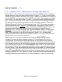
Panel / Rack Mount Enclosure
6.1
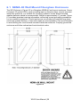
NEMA 4X Wall Mount Fiberglass Enclosure
6.2
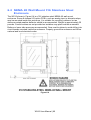
NEMA 4X Wall Mount 316 Stainless Steel Enclosure
6.3
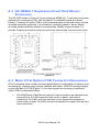
XP NEMA 7 Explosion-Proof Wall Mount Enclosure
6.4
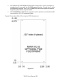
Main I/O & Option PCB Footprint Dimensions
57
57
58
60
61
61
SECTION - 7
.
7.0
Adding The “Wireless” Radio Kit Option
7.1
Radio Setup Menu
7.2
Wireless Receiver Mode
7.2.1
Radio Status Alarms - Wireless Receiver Mode
7.3
Wireless ModBus Slave Mode
7.4
Wireless ModBus Master Mode
7.5
Antenna Selection
7.5.1
Dipole And Collinear Antennas
7.5.2
Yagi Antennas
7.5.3
Mounting Near Other Antennas
7.5.4
Coax Cables
7.6
Surge Protection & Grounding
7.6.1
Antenna Grounding
7.6.2
Connections to Other Equipment
63
63
64
65
65
66
67
67
67
68
68
68
69
69
70
WX16 User Manual | 6
SECTION - 1 .
Important Safety Issues
The following terms and symbols are used in this manual to alert the operator of
important instrument operating issues:
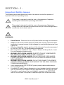
This symbol is intended to alert the user to the presence of important
operating and maintenance (servicing) instructions.
This symbol is intended to alert the user to the presence of dangerous
voltage within the instrument enclosure that may be sufficient magnitude to
constitute a risk of electric shock.
WARNINGS:
Shock Hazard - Disconnect or turn off power before servicing this instrument.
NEMA 4X wall mount models should be fitted with a locking mechanism after
installation to prevent access to high voltages by unauthorized personnel (see
Figure 6.2).
Only the combustible monitor portions of this instrument have been assessed
by CSA for C22.2 No. 152 performance requirements.
This equipment is suitable for use in Class I, Division 2, Groups A, B, C, and
D or non-hazardous locations only.
WARNING- EXPLOSION HAZARD- SUBSTITUTION OF COMPONENTS
MAY IMPAIR SUITABILITY FOR CLASS I, DIVISION 2.
WARNING- EXPLOSION HAZARD- DO NOT REPLACE FUSE UNLESS
POWER HAS BEEN SWITCHED OFF OR THE AREA IS KNOWN TO BE
NON-HAZARDOUS.
WARNING- EXPLOSION HAZARD- DO NOT DISCONNECT EQUIPMENT
UNLESS POWER HAS BEEN SWITCHED OFF OR THE AREA IS KNOWN
TO BE NON-HAZARDOUS.
Use a properly rated CERTIFIED AC power (mains) cable installed as per
local or national codes
A certified AC power (mains) disconnect or circuit breaker should be mounted
near the controller and installed following applicable local and national codes.
If a switch is used instead of a circuit breaker, a properly rate CERTIFIED
fuse or current limiter is required to installed as per local or national codes.
WX16 User Manual | 7
Markings for positions of the switch or breaker should state (I) for on and (O)
for off.
Clean only with a damp cloth without solvents.
Equipment not used as prescribed within this manual may impair overall
safety.
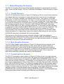
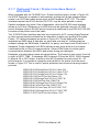
1.0 General Description
The Oldham WX16 Sixteen Channel Controller is designed to display and control
alarm event switching for up to sixteen sensor data points. It may also be set as an
eight channel controller for applications needing fewer inputs. Alarm features such as
ON and OFF delays, Alarm Acknowledge, and a dedicated horn relay make the WX16
well suited for many multi-point monitoring applications. Data may be input to the
®
WX16 by optional analog inputs or the standard ModBus RTU master RS-485 port. A
ModBus RTU slave RS-485 port is also standard for sending data to PC’s, PLC’s,
DCS’s or even other WX16 Controllers. Options such as analog I/O and discrete relays
2
for each alarm are easily added to the addressable I C bus. Option boards have 8
channels and therefore require 2 boards for 16 channel applications.
In addition to traditional analog and serial methods of providing monitored values, the
WX16 is also capable of sending and receiving wireless data as described in section 7
of this manual.
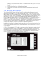
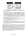
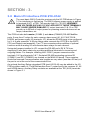
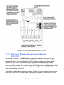
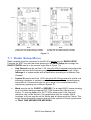
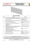
A 240 x 128 pixel graphic LCD readout displays monitored data as bar graphs, trends
and engineering units. System configuration is through user friendly menus and all
configuration data is retained in non-volatile memory during power interruptions. The
WX16 front panel is shown below in Figure 1.0 displaying the 8 channel bar graph
screen. Additional data screens are shown in Figure 2.0.
Figure 1.0
WX16 User Manual | 8
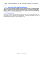
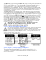
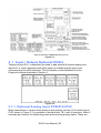
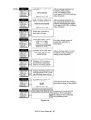
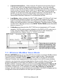
1.1 Data Display Screens
The WX16 Controller offers three distinct graphic displays for depicting the monitored
data. These are Bar Graphs, 24 Hour Trend and Combination. Each is shown in Figure
2.0.
1.1.1 Trend Screen
The WX16 Trend screen shown in Figure 2.0 displays a 24-hour trend of input data for
the channel selected. Horizontal tic marks are each hour and vertical tick marks are
each 10% of full scale. Dashed lines indicate alarm levels. The graphic LCD is 240
pixels wide, so each pixel represents 1/10 hour, or 6 minutes worth of data. The trend
is 100 pixels high, so each represents 1% of full scale in amplitude. Since each data
point must be collected for 6 minutes before it may be displayed, it is likely input values
will fluctuate during this interval. Therefore, MAX, MIN and AVERAGE values are
stored in RAM memory for each 6-minute subinterval. To accurately portray the trend,
a vertical line is drawn between MIN & MAX values for each 6-minute subinterval. The
AVERAGE value pixel is then left blank, leaving a gap in the vertical line. This is
demonstrated in the noisy area of the 24-hour trend in Figure 2.0. If the MAX & MIN
values are within 2% of each other, there is no need for the vertical line, and only the
AVERAGE value pixel is darkened as in the quiet areas.
The top portion of each trend screen indicates channel #, real time reading in
engineering units, measurement name, range, and MIN, MAX & AVERAGE values for
the preceding 24-hour period. The SI field on the top right indicates number of seconds
remaining in the current 6-minute subinterval.
1.1.2 Bar Graphs Screen
The WX16 Bar Graphs screen shown in Figure 2.0 allows all active channels to be
viewed simultaneously. Both engineering units values and bar graph values are
indicated in real time. Lines across the bars indicate the alarm trip points making it
easy to identify channels at or near alarm. A feature in the Systems menu tree allows
new alarms to always force the LCD to the bar graphs screen. This is useful for
applications requiring channels with alarms to be displayed.
1.1.3 Combination Screen
The WX16 Combination screen shown in Figure 2.0 offers a view of a single channel
but displays the data as a 30-minute trend, bar graph and large engineering units. It is
also useful for testing inputs for stability since MAX, MIN & AVERAGE values refresh
each time this screen is selected. For example, to test stability over a one-hour period
for an input, begin timing as soon as the channel is selected. One hour later, record the
MAX, MIN & AVERAGE values. The difference between MAX & MIN indicates peak to
peak excursions over the one-hour period and AVERAGE is the average for the hour.
Longer or shorter tests may also be run. The numeric value shown below the bar graph
indicates number of minutes samples have been taken. After 999 minutes the
AVERAGE buffer overflows and the message ERROR appears in the AVERAGE field.
Exiting this screen resets the buffer and clears the error message.
WX16 User Manual | 9
1.2 Specifications
1.2.1 DC Power Supply Requirements
Standard WX16 power requirements are 10-30 VDC @ 3 watts applied to terminals 9
& 11 of TB2 on the standard I/O PCB (see section 3.0). Optional features increase
power consumption as described below:
Discrete Relay PCB option; add 2 watts per PCB (assumes all 8 relays are
energized).
Analog Input PCB option; add 1/2 watt.
4-20mA Output PCB option; add 1 watt.
Catalytic Bead Sensor Input option; add 12 watts max (assumes maximum sensor
power consumption).
TB2 terminals 10 & 12 of the standard I/O PCB provide a maximum of 500mA
fused output power for powering of auxiliary external devices such as relays,
lamps or transmitters. Power consumed from these terminals should be
considered when calculating system power consumption.
1.2.1.1 150 Watt AC – 24 VDC Power Supply
* 110-120 VAC @3.2A max
* 220-240 VAC @ 1.6A max
* A slide switch on the front of the power supply selects AC input range.
The 10-0172 150 watt power supply (Figure 3.8) is for powering the WX16 and up to
16 detectors. A minimum of 5 watts per channel is available for powering of external
transmitters.
1.2.2 Relays
Common relays are standard and menus provide voting logic for
ALARM 1, ALARM 2, FAULT and HORN. Discrete relays are optional. All
relays are rated at 5 Amp for 28 VDC and 250 ~VAC RESISTIVE loads.
IMPORTANT: Appropriate diode (DC loads) or MOV (AC loads) snubber devices must
be installed with inductive loads to prevent RFI noise spikes. Relay wiring should be
kept separate from low-level signal wiring.
1.2.3 Ambient Temperature Range
-25 to 50 degrees C
1.2.4 Humidity Range
0 to 90% R. H. Non-Condensing
1.2.5 Altitude
Recommended up to 2000 meters
1.2.6 Housings
General purpose panel mount weighing 7 lbs and including hardware for 19” rack
mounting (Figure 6.1).
* NEMA 4X wall mount in fiberglass enclosure weighing 17 lbs (Figure 6.2).
WX16 User Manual | 10
* NEMA 7 wall mount suitable for DIV 1&2 Groups B,C,D weighing 110 lbs (Figure
6.4).
* Includes non-intrusive magnetic keypad.
1.2.6.1 Non-Intrusive Magnetic Keypad
The WX16 operator interface includes five front panel touch keys. A magnetic keypad
option offers these five keys with adjacent magnetic keys. This option is included as a
standard feature. It is useful in applications where it may be inconvenient to open the
enclosure’s door to access the touch keypad.
1.2.7 Approvals
CSA C22.2 No 1010.1 and ISA S82.02; CSA C22.2 No 152 for combustibles; UL 1604
/ C22.2 No 213 (Div 2 Groups A,B,C,D); EN55011 & EN61000 (CE Mark). CSA File # =
252022 and may be seen at: CSA-International.org.
WX16 User Manual | 11
WX16 User Manual | 12
SECTION - 2 .
2.0 Basic Operation
The WX16 offers 3 graphic screens for viewing monitored data and a Setup menu
screen for operator interface to configuration menus. They are shown below in Figure
2.0. The Bar Graphs screen allows viewing of all active channels simultaneously. The
Trend screen displays a 24-hour trend one channel at a time. The Combination screen
displays a bar graph, large engineering units and a
30-minute trend one channel at a time. Input channels may be displayed in sequence
with the UP/DOWN keys. The NEXT key switches between the 3 graphic data screens.
When WX16 power is applied, the graphic LCD returns to the screen active when
power was last removed.
Setup menus are entered by pressing EDIT from any data screen, and scrolling to the
desired menu using the UP/DOWN keys. Pressing EDIT again enters the selected
menu’s tree of variables. This Setup mode may be exited manually by pressing NEXT,
or automatically when no keys are pressed for 5 minutes. Alarm relays and front panel
alarm LED indicators remain active during the Setup mode. An AUTHORIZE menu
offers a password feature to prevent tampering with WX16 parameters.
Figure 2.0
WX16 User Manual | 13
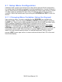
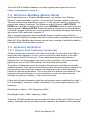
2.1 Setup Menu Configuration
Variables inside system and channel menu trees allow optimum WX16 configuration
for a wide range of demanding multi-point monitoring applications. Access to menus is
via the Setup mode by pressing EDIT and activating the Setup screen shown in Figure
2.0. Menu trees are provided for each of the 16 channels and another for system
variables. Select the desired menu by scrolling with UP/DOWN and EDIT to enter the
menus.
2.1.1 Changing Menu Variables Using the Keypad
Upon entering a menu, a pointer controlled by the UP/DOWN keys indicates the
selected variable. Some are simple YES/NO or ON/OFF entries toggled by pressing
the EDIT key. Others, such as Measurement Name and Eunits fields may have many
ASCII character possibilities. Allowed ASCII characters are as follows:
ABCDEFGHIJKLMNOPQRSTUVWXYZabcdefghijklmnopqrstuvwxyz blank space
!"#$%&`()*+,-./0123456789:;<=>?@. EDIT places a cursor over the item and
UP/DOWN scrolls through each allowed entry. The NEXT key moves the cursor to the
next position within a field. When the field is complete, EDIT clears the cursor and
loads it into non-volatile memory where it is retained indefinitely. With no cursor
present, NEXT closes open menus in reverse order and returns the LCD to the most
recent data display.
WX16 User Manual | 14
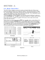
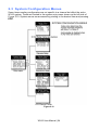
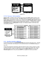
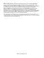
2.2 Channel Configuration Menus
Figure 2.1 illustrates the menu tree for configuring Channel variables. These items
affect only the specific channel selected. System specific variables are in the menu
tree shown in section 2.3.
Figure 2.1
WX16 User Manual | 15
2.2.1 Channel Setup Entry Menu
The entry menu shown on the left side of Figure 2.1 allows access to all configuration
variables for the selected channel. These are, Alarm 1, Alarm 2, Alarm 3, Data
From?, Linearize, Configure and Calibrate.
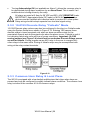
2.2.2 Alarm 1 / Alarm 2 / Horn Relay Setup Menu
Alarms 1 and 2 are identical except A1 may not be acknowledged and front panel LED
indicators are yellow while A2’s are red. Since their configuration menus are the same,
only one is shown in Figure 2.2 for clarity.
Figure 2.2
The first entry determines the Setpoint value where the alarm trips. It is entered in
engineering units. For example, if a channel monitors 0-50 ppmH2S and the alarm
must trip at 10 ppm, the correct entry is 10.00.
Latching determines either manual or automatic alarm reset operation. YES
requires a manual Alarm Reset to unlatch the alarm even though an alarm
condition no longer exists. YES also causes this alarm group’s common relay,
front panel LED, and optional discrete relay to latch. NO allows all outputs for this
alarm to automatically reset as soon as the alarm condition clears.
TRIP ON is set to HIGH for increasing alarms or LOW for decreasing alarms to
determine if the alarm activates upon exceeding or falling below the setpoint.
The ON DELAY / OFF DELAY entries allow ON and OFF time delays affecting
how long the setpoint must be surpassed before an alarm event transition occurs.
ON delays are limited to 10 seconds while OFF delays may be as long as 120
minutes. Delays are useful in many applications to prevent nuisance alarms and
unwanted cycling into and out of alarm conditions.
The HORN ON entry allows linking this alarm to the common horn relay. NO
causes the alarm to have no effect upon the horn relay. Entering YES causes this
alarm to turn the horn relay on steady, or, to pulse it depending upon horn
configuration in they system menu (see section 2.3.1).
Discrete LED indicators on the front panel indicate the status of each alarm and relay.
Any new alarm event causes the associated LED to flash until Alarm Reset occurs
causing an acknowledged steady on condition. Operators should recognize new
alarms by a flashing LED. Alarm Reset also acknowledges, or deactivates, the horn
relay until another new alarm occurs.
WX16 User Manual | 16
All relays are rated at 5 Amp for 28 VDC and 250 ~VAC RESISTIVE loads.
IMPORTANT: Appropriate diode (DC loads) or MOV (AC loads) snubber
devices must be installed with inductive loads to prevent RFI noise spikes.
Relay wiring should be kept separate from low-level signal wiring.
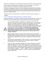
2.2.3 Alarm 3 / Fault Alarm Menu
The discrete channel alarms identified as Alarm 3/Fault may be configured either as a
rd
3 level alarm, or, as a Fault alarm indicating the input is out of range in the negative
direction. When used as a level alarm, features such as on / off delays, latching and
trip direction are also available. It is important to understand that though discrete
channel alarms (LED’s & optional discrete relays) may be set as Alarm 3 level alarms,
the common relay for this group is always a Fault alarm. The fault out of range
threshold for the channel is the most recent Fault trip point entered prior to changing
the menu to Alarm 3. The following example describes how to configure both the Fault
out of range and Alarm 3 level trip points for a channel. Example: If the common Fault
relay must trip as the input falls below negative 10% of full scale, and, the discrete
alarms trip as the input exceeds a level, then the –10% Fault setpoint must be entered
first. Toggle the TYPE menu entry to FAULT and enter –10.00% into the setpoint
entry. Next, toggle the menu back to LEVEL and enter the desired Alarm 3 level
setpoint. The -10% Fault value is retained in memory even though it no longer appears
on the menu.
Figure 2.3
2.2.4 Data From? Menu to Set Input Source
Channels may be independently configured to accept input data from the following
sources (also see Figure 2.4):
An analog input PCB attached to the I C bus.
A sensor input PCB attached to the I C bus.
The ModBus RS-485 master port connected to ModBus slave devices.
Note: Each ModBus menu selection also requests the RTU # and the Alias
register # location of the data to be retrieved from the RTU. Alias register
numbers define the location of the variable representing the input value and
must be obtained from the manufacturer of the ModBus RTU device.
2
2
WX16 User Manual | 17
Our 10-0288 Radio Modem may be connected to the ModBus RS-485 master
port to enable wireless communication to OLCT 200 wireless sensor
transmitters.
EDIT toggles the Data From entry between Analog, Analog with Local Cal or Sensor
Direct, WIRELESS RF900 and ModBus RTU (signed, unsigned & floating point).
Analog should be selected when the channel’s input comes from a transmitter or
monitoring device with a calibrated output such as 4-20mA. Analog with Local Cal is
available when the WX16 will be the point of calibration for the analog input. Sensor
Direct is identical to Analog with Local Cal and both activate the WX16’s Cal Mode
features (see section 2.2.7). Problems may arise if calibrations are performed in two
places upon the same signal, so Cal Mode menus are only visible when Sensor Direct
or Analog with Local Cal is selected. These selections should only be used when the
input originates from a non-calibrated signal source such as the Bridge Sensor Input
option described in section 3.1.3. These applications require the WX16 to be used as
the calibration point, since the sensors have no zero or span controls.
Figure 2.4
2.2.4.1 Min / Max Raw Counts Menus
The Min Raw and Max Raw counts entries included in Input Data From: menus define
the range of input counts that provide Measurement Range read-out values described
in section 2.2.6b. This menu entry is determined by the A/D converter resolution of the
channel’s input. For example, if the input is a 10 bit ModBus device with zero at 200
counts and 100% at 1000 counts, then this menu’s MIN should be set at 200 and MAX
at 1000. If communicating with the WX16’s optional 12 bit Analog Input PCB, the MIN
should be 800 and the MAX 4000.
If the input device’s resolution is unknown, the live counts variable on the bottom of the
screen displays actual raw A/D counts currently being read by this channel. This
reading may be used to test the input device for what A/D counts are provided for zero
and 100% if these values are unknown. Forcing the input device to read zero should
provide the A/D counts value needed to make this channel’s display also read zero.
Likewise, forcing the input device to read 100% should provide the A/D counts value
needed to make the WX16 channel’s display also read 100%.
WX16 User Manual | 18
If ModBus 32 BIT is selected, a Byte Order entry appears at the bottom of the menu.
This determines WORD and BYTE alignment of data at the remote ModBus transmitter
when sending its 4 byte IEEE Floating Point values. With the pointer on this entry, the
EDIT key toggles between the 4 possible modes. Min / Max Raw values are not used
in this mode.
Note Each Data From: item has a matching default Min/Max counts value of 20% to
100% with ± 5% over/under range applied. If the default value is incorrect for the input
device it should be edited.
2.2.4.2 Marker Menus
Some transmitters or monitoring devices providing WX16 inputs also indicate special
modes of operation, such as Calibration, Maintenance or Fault, by transmitting a
special <4mA or negative “Marker” value. The WX16 offers channel Marker menus for
detecting and indicating such events (see Figure 2.5). While active, the WX16 displays
a 6-digit ASCII message to indicate the special event, and if equipped with 10-0167 420mA output option, the WX16 also transmits the same <4mA value.
Marker Enabled turns the marker feature ON and OFF
The negative Marker value is entered into the Marker % field as a negative
percent of full scale. For example, -15.62% of full scale detects a marker value of
1.5mA (1.5mA is -15.62% of full scale when 4-20mA is the range).
The Mark As menu allows user entry of the 6-digit ASCII message to be displayed
when the marker is detected.
Figure 2.5
2.2.4.3 Sensor Life Detection
Sensor Life should only be activated when the Marker event is Calibration and when a
sensor life value is transmitted after each calibration. This feature is provided primarily
for use when interfacing the WX16 to Oldham’s OLCT 200 Transmitters, which may be
configured to transmit sensor life values after each calibration (see Figure 2.6). For
Sensor Life to record properly, the monitor must perform as follows: After the
Calibration Marker interval, 4.0mA transmits for 10 seconds to indicate its calibration
mode is complete. The monitor then transmits between 4.0mA and 5.0mA for five
seconds depending on remaining sensor life where 4.0mA = 0% and 5.0mA = 100%
remaining sensor life. The WX16 reads this value and records it as the channel’s
Sensor Life. Sensor Life is stored in the WX16 ModBus database and displayed as a
WX16 User Manual | 19
bar-graph in the Sensor Info screen (see section 2.3.6). It is a useful tool for planning
sensor replacement schedules.
Figure 2.6
2.2.5 Linearization Menu
The linearization menu allows each channel to have its own linearization curve stored
in the controller’s non-volatile memory. Input versus output points must be entered in
percent of full scale values. This means if the range is 0-200 ppmH2S, then 100 ppm is
50% of full scale. Zero input will provide a zero output and 100% input a 100% output.
Nine intermediate points may be entered to define the curve.
Figure 2.7
2.2.6 Configure Menu
From the entry level setup menu in Figure 2.8, the CONFIGURE menu may be entered
for setting variables defining how the controller presents monitored data to the various
graphic displays.
WX16 User Manual | 20
Figure 2.8
2.2.6.1 Eunits / Measurement Name ASCII Data Fields
The first two items in this menu are for entering the 6 character engineering unit and 16
character Measurement Name ASCII fields. Eunits should define the units of measure
for what this channel is to display. Measurement Name should describe the source of
this data in the user’s terminology. Section 2.1.1 of this manual describes how to use
the front keypad to modify these fields.
2.2.6.2 Input Measurement Range
The ZERO / SPAN entries allow configuration of the measurement range displayed by
this channel. Measurement Range works along with A/D Counts menus, described in
section 2.2.4a, to define the range of the input signal’s engineering units. For example,
if a channel’s input is 4-20mA from a transmitter monitoring 0 to 10ppm chlorine, then
the Zero value should equal 0.000 and the Span value equal 10.00. The six ASCII
engineering units previously entered are automatically displayed at the top of each
menu as a reminder. Four digits must appear in this entry, so trailing 0’s may appear
here that are not displayed on other data screens.
2.2.6.3 Decimal Point Resolution
Resolution of displayed channel values is configured in this menu by setting the
number digits trailing the decimal point. Values are limited to a maximum of four digits,
and a polarity sign. An auto-ranging feature displays the highest resolution allowed by
this menu’s decimal point entry. For example, if three decimal points are entered, and
the range is 0 to 100ppm, the reading will be 0.000 at 0ppm and 100.0 at 100ppm.
However, this may be undesirable due to the high resolution at zero unless the
sensor’s output is extremely stable. If decimal points are limited to one, the 0ppm
reading becomes 0.0 and the 100ppm reading remains 100.0. Resolution may be
limited further by setting decimal points to 0. In the above example, this would cause
0ppm to display 0 and 100ppm to display 100.
2.2.6.4 Turning Off Unused Channels
The Channel On? entry determines if this channel is to be utilized. Turning it off will
cause the controller to never process inputs applied to this channel and no alarms will
be tripped or data displayed. Inactive channels have a line drawn through them on the
Setup screen as indicated by channels 15 & 16 in Figure 2.0. If less than 9 channels
are to be activated, the WX16 may be set for 8 channel mode, deactivating channels 9-
WX16 User Manual | 21
16. This is done in the System Setup menu described in section 2.3. The WX16 will
only allow 15 channels to be turned off. At least one channel must remain on
2.2.6.5 Copy Data To?
This menu simplifies the Setup procedure by allowing similar channels to be copied
from one to another. For example, if all channels are identical except for the
Measurement Name entry, channel 1 could be configured and copied to channels 2 –
16. Only Measurement Name then must be configured on channels 2 – 16. Use EDIT
to increment channel numbers and UP/DN to point to Copy Now? Press EDIT once
more to copy.
2.2.7 Cal Mode
IMPORTANT! Each channel’s CALIBRATION menu is inactive unless its Input Data
From: menu, described in section 2.2.4, is set for Analog with Local Cal or Sensor
Direct. WX16 CAL MODE features allow pushbutton calibration of zero and span
values. This feature should be utilized only when there are no other zero/span controls
within the monitoring system, since it is inappropriate to calibrate a signal at more than
one point. Therefore, if calibration is to be performed at another transmitter or
monitoring device, the WX16 CAL MODE feature should not be used.
The CALIBRATION MENU allows entering the correct Cal ZERO & Cal SPAN setpoint values needed to calibrate the sensor. These are entered in the same
engineering units as input range. Set Zero & Set Span controls in this menu allow
pushbutton calibration by moving the pointer to each and pressing the EDIT key. A live
reading of the channel’s value allows calibration checks to see if an adjustment is
needed. Unintentional calibrations are reset by the Unity Gain menu item. Unity Gain
resets zero offset to 0 and span gain to 1. It is useful for returning the calibration to a
known starting place. Sensor aging may be monitored by recording zero and span
readings at Unity Gain when it is new, and again at later dates when degradation may
have occurred.
To check zero calibration, apply the ZERO calibration value to the sensor and observe
the live reading. If the zero reading differs from the zero setpoint, a calibration is
needed. To calibrate zero, move the pointer to Set Zero and press EDIT. A warning
message explains that pressing EDIT again will change the zero calibration and any
other key will exit. The procedure for span calibration is identical. For example, if an
LEL combustible sensor is to be spanned with 50% LEL span gas, the span set-point
must be 50%. If 45% LEL is to be used later, the span set-point must be changed to
45% to match the span calibration gas. If the reading is only 40% LEL with the 50%
gas applied a span calibration is needed. Move the pointer to the Set Span entry and
press EDIT twice. Unity Gain may be used at any time to cancel incorrect calibrations
and start again.
WX16 User Manual | 22
Figure 2.9
WX16 User Manual | 23
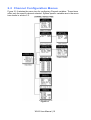
2.3 System Configuration Menus
Some items needing configuration are not specific to a channel but affect the entire
WX16 system. These are located in the system entry menu shown on the left side of
Figure 2.10. System menus are accessed by pointing to the desired item and pressing
EDIT.
Figure 2.10
WX16 User Manual | 24
2.3.1 Common Alarm Relays 1 & 2
READ THIS SECTION CAREFULLY AND TEST ALL SETTINGS BY
SIMULATING WX16 INPUT CONDITIONS THAT SHOULD ACTIVATE
THESE ALARM RELAYS!
Common Relay 1 & Common Relay 2 menus are identical and therefore discussed
only once. It is very important to fully understand these menus, since they determine
the functions of each common relay.
Figure 2.11
The Group menu entry offers additional flexibility by controlling which channels
trip this menu’s common alarm relay. The 3 choices are 1-16, 1-8 or 9-16. Some
applications have different types of sensors, or, sensors in different areas
connected to the same WX16 Controller. In these cases, it may be undesirable for
a sensor on channel 9 to trip the same relay as a sensor on channel 2. The Group
menus may restrict this. For example, channels 1-8 might be set to trip common
relay 1 while channels 9-16 trip common relay 2. Another possibility is channels 18 be set to trip common relay 1 while channels 9-16 trip relays on an optional
discrete relay PCB configured for Alarm 1 (see section 3.2).
Failsafe controls relay activation for this common relay. Failsafe ON causes the
relay to de-energize during alarm conditions and energize when there is no alarm.
Thereby, a power failure forces the relay contact to the alarm position. Note the
common Fault relay is always failsafe and may be monitored separately to indicate
loss of power conditions in many applications.
A1 and A2 Votes allows creation of logical AND function equations that control
common relay 1 & common relay 2. Default settings for common relay 1 are A1
Votes = 01 and A2 Votes = 00, which cause relay 1 to trip if any channel has an
A1 level alarm active. Default settings for common relay 2 are A1 Votes = 00 and
A2 Votes = 01, which cause relay 2 to trip if any channel has an A2 level alarm
active. Example: If either default setting is modified such that A1 Votes = 02 and
A2 Votes = 01, then any two channels must have an A1 level alarm active and
any one channel must have an A2 level alarm active to trip that relay.
REMEMBER! One of the A1’s and the A2 could be on the same channel. These
level alarms must come from a channel included in the Group entry described
above.
WX16 User Manual | 25
Turning Acknowledge ON (not available on Alarm 1) allows the common relay to
be deactivated during alarm conditions by an Alarm Reset. This is useful if an
audible device is being driven by the relay.
All relays are rated at 5 Amp for 28 VDC and 250 ~VAC RESISTIVE loads.
IMPORTANT: Appropriate diode (DC loads) or MOV (AC loads) snubber
devices must be installed with inductive loads to prevent RFI noise spikes.
Relay wiring should be kept separate from low-level signal wiring.
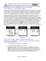
2.3.2 10-0195 Discrete Relay “Failsafe” Mode
10-0195 Discrete relay options may also be configured to function in a Failsafe mode
using the System Setup menu shown in Figure 2.12. Entering YES causes these
discrete relays to have energized coils when no alarm condition exists for the
associated channel and de-energized coils when the alarm occurs. Failsafe is useful
for indicating failed relay coils and loss of power conditions. Important: 10-0195
zoning jumpers (see Figure 3.4) should not be used when Discrete Relays menus
are set for failsafe. Zoning jumpers cause ANY relay in the zone to energize ALL
other relays in the same zone. Zoning of failsafe relays may be accomplished with
wiring at the relay contact terminals.
Figure 2.12
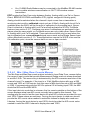
2.3.3 Common Horn Relay & Local Piezo
The WX16 is equipped with a low-decibel audible piezo that chirps when keys are
pressed and may be configured to audibly indicate alarm conditions. The common horn
relay is similar to the common A1 & A2 common relays.
WX16 User Manual | 26
Figure 2.13
Turning Piezo Alarm ON causes the audible piezo to duplicate the action of the
horn relay. This feature may be used to provide a low-decibel indication of the
status of the system’s horn.
Alarm 1 & Alarm 2 menus control how this alarm level from each channel will
affect the common horn relay. Choices are OFF, ON or BEEP (one Hz. Pulsating).
As an example, A2 conditions might pulse the horn (BEEP) and A1 conditions to
cause a steady horn (ON). Any other combination of these 3 choices is possible
for A1 and A2 levels affecting the horn relay. This feature is very useful since it
allows the horn relay to serve as another level A1, level A2 or both for channels 116, 1-8 or 9-16. Individual channel alarms may also be configured to not affect the
Horn relay on a channel by channel basis (see section 2.2.2).
Failsafe & Horn Group menu entries are identical to the descriptions for menus
Common Relay 1 & Common Relay 2 in section 2.3.1.
Turning Acknowledge OFF allows the common Horn relay to drive devices other
than horns or sirens, such as a light or a fan.
Display Alm YES forces the LCD to display the Bar Graphs screen upon any new
alarm. This feature is offered to satisfy applications requiring channels in alarm to
be displayed automatically (all channels are displayed on the Bar Graphs screen).
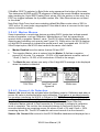
2.3.4 Comm Port Menus
The system Comm Port menu allows setting RTU Slave ID address, Slave Baud rate,
Parity and UART Timer for the comm2 slave ModBus serial port (comm1 master port
ID settings are per channel as described in section 2.2.4). This slave port may be used
to transfer WX16 data to a host device such as a PC, PLC, DCS or even another
WX16. The slave port is addressable, allowing many WX16 controllers to be connected
to a single RS-485 cable. The UART Timer setting is disabled with 00 seconds
entered. Entering a value causes the comm2 slave ModBus serial port to reinitialize if
no ModBus query is processed within this time period. This ensures against serial port
lockup. Section 5 of this manual provides important information describing how to
interface to the WX16’s ModBus slave port.
WX16 User Manual | 27
The Mastr TO (master time out) and Mastr PR (master poll rate) menu items affect the
WX16’s master ModBus port. Time out sets length of time in milliseconds before a
communications error. Three consecutive timeout errors must occur before a
communication error is indicated. This item is useful for optimizing throughput to the
WX16 from other slave RTU’s. Poll Rate sets frequency of data requests to the RTU’s
in milliseconds. This is useful when an RTU is limited in how fast it may respond to
consecutive data requests.
The Echo ACK (echo acknowledge) menu allows alarm reset / alarm acknowledge
functions be sent from the ModBus master port to connected ModBus slave devices
having ModBus coil 2001 assigned as the reset / acknowledge coil. This menu may be
set to OFF, LCL (local) or MB/LCL (ModBus/local). Off disables the feature and 2001
coils of slave devices are unaffected. LCL only writes to the 2001 coils of connected
RTU’s when the local Reset pushbutton is pressed. MB/LCL writes these coils if this
WX16’s 2001 coil has been reset via mobus AND when the local pushbutton is
pressed. The MB/LCL option is useful if WX16s are being cascaded from an HMI or
other ModBus master. A short time delay between reset of remote RTU’s and the
primary WX16 may occur, since remote resets are processed first.
IMPORTANT! ALL MODBUS 2001 COILS ARE WRITTEN BY THIS
FEATURE. DO NOT CONNECT DEVICES WITH 2001 COILS
CONTROLLING OTHER CRITICAL EVENTS!
2.3.4.1 Master Port Radio Setup Menu
The radio kit option may be connected to the comm1 master port and receive
wireless data transmissions from up to sixteen of Oldham’s OLCT 200
wireless sensor transmitters. It is not possible to also use the comm1 master
port to communicate to “wired” ModBus transmitters, and if any channels are set for
ModBus, they will report “comm. error”.
See Section 7 for a detailed discussion of WX16 wireless operation.
Figure 2.14
2.3.5 Eight / Sixteen Channel Modes
The system menu allows setting the WX16 controller to accept either 8 or
16 channels. If 8 channels are selected by this menu, they are channels 1-8,
and 9-16 are disabled.
WX16 User Manual | 28
Figure 2.15
2.3.6 Sensor Information
Sensor Info is available when at least one channel has Sensor Life activated in the
Marker menu (see section 2.2.4b). The Sensor Info screen displays each channel’s
sensor status as illustrated in Figure 2.16. Channels with Sensor Life disabled indicate
Option Disabled above the corresponding empty bar graph. If Sensor Life is enabled,
the channel will have its Measurement Name above the bar, or, an empty bar with a
Cal Required label. Cal Required indicates no Calibration Marker value has been
received by the WX16.
Figure 2.16
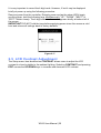
2.4 Authorization Mode
A password entered in the AUTHORIZATION menu allows locking all menus. Viewing
menus is not denied, but attempts to edit variables flashes the Locked message on
the LCD.
Authorized individuals locking the system should first enter a name, phone # or other
contact information into the 10-digit field. To lock or unlock the system, the correct 4digit authorization number must be entered into the Enter Code field. Point to the
Unlock System menu entry and press EDIT to complete the unlock procedure.
WX16 User Manual | 29
It is very important to record the 4-digit code. However, if lost it may be displayed
briefly at power up using the following procedure:
Remove power from the controller. Reapply power and as the alarm LED's begin
scrolling down, hold the following keys simultaneously "UP", "DOWN", "NEXT", &
"EDIT". Watch closely. The 4-digit authorization code appears briefly at bottom left of
the screen.
IMPORTANT! DO NOT hold the keys before applying power since this causes a cold
boot and returns all settings back to factory defaults.
Figure 2.17
2.5 LCD Contrast Adjustment
The Setup menu item identified as CONTRAST allows users to adjust the LCD
contrast to a level suitable to the ambient lighting. Selecting CONTRAST and pressing
EDIT causes the UP/DOWN keys to increase and decrease LCD contrast.
WX16 User Manual | 30
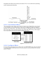
SECTION - 3 .
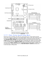
3.0 Main I/O Interface PCB #10-0142
The most basic WX16 Controller requires only the I/O PCB shown in Figure
3.1 for interfacing to field wiring. The WX16 primary power supply is applied
to terminals 9 & 11 of TB2. This may be from 10 – 30 VDC. WARNING!
HIGH VOLTAGES SUCH AS 115 VAC APPLIED TO THESE TERMINALS
MAY CAUSE SEVERE DAMAGE! DC output terminals 10 & 12 on TB2
provide up to 500mA of output power for powering remote devices such as
lamps, transmitters, etc.
This PCB includes both master (COMM 1) and slave (COMM 2) RS-485 ModBus
ports, 5 amp form C relays for each common alarm event (A1, A2, FAULT/A3 &
HORN), and power supply I/O terminals. JP1 allows the RS-485 ports to be configured
for 2- or 4-wire operation. A 26-pin ribbon cable connects the I/O PCB to the WX16
2
CPU and Display nest assembly. Two I C bus connectors allow addition of optional
functions such as analog I/O and discrete alarm relays for each channel.
Horizontal jumpers installed in JP1 connect the RS-485 port’s RX & TX lines,
simplifying 2-wire daisy chains by providing additional terminals for incoming and
outgoing cables. For example, installing the 2 COM 1 jumpers connects screw
terminals 1 & 5 and terminals 3 & 7. Socketed RS-485 terminating resistors R6
(COMM 1) and R12 (COMM 2) are located on the MAIN I/O board. These resistors
should be removed if communication wire lengths are very short (less than 25 feet) or if
the port is not at the end of the communication line.
An optional Auxiliary Relays piggyback PCB (part #10-0144) may be added to the I/O
PCB via ribbon cable J4. These add another form C contact set to the common A1, A2
and HORN alarms. Auxiliary Relay contacts are available at the TB1 (AUX) terminals
shown in Figure 3.1.
WX16 User Manual | 31
Figure 3.1
3.1 Input / Output Optional PCB’s
Telephone style RJ11 connections are used to add optional 8 channel analog and
digital I/O. A screen appears briefly after power up indicating what options are
connected and for which channels. This information is also available from the
Diagnostics Mode described in Section 4.
Figure 3.2
3.1.1 Optional Analog Input PCB #10-0158
Many transmitters or sensors have analog output signals, and the 12 bit Analog Input
PCB, shown in Figure 3.3, is available to accept these. TB1, with 24 positions, offers 3
terminals per channel for distributing power and receiving analog inputs. These are
WX16 User Manual | 32
EXC and HI / LO inputs. TB2, with only two positions, is for connecting the power
supply for powering external transmitters. Precision 100 ohm resistors (R1 – R8)
between each channel’s IN LO and IN HI terminals are socketed termination resistors
for 4-20mA inputs. These may be removed if voltage inputs are to be applied.
EXC and IN LO terminals are bussed together internally. EXC terminals are tied
directly to TB2-1 (+) and IN LO terminals are tied to TB2-2 (-). Bussing allows
transmitter power to be brought into the system at a single point (TB2) and distributed
back out at each channel’s EXC / IN LO terminals to simplify field wiring. Figure 3.3
includes typical wiring to 2- & 3-wire 4-20mA transmitters.
JP1 determines if the 8 analog inputs are applied to channels 1-8 or channels 9-16.
Connecting more than 8 analog inputs requires 2 PCB’s with one JP1 set for channels
1-8 and the other set for channels 9-16.
WX16 User Manual | 33
Figure 3.3
3.1.2 Optional Discrete Relay PCB #10-0195
An optional Discrete Relay PCB, shown in Figure 3.4, adds eight 5 amp (resistive) form
C relays per sixteen channel alarm group (2 PCB’s required when utilizing more than 8
channels). Each PCB may be configured via rotary switch S1 to function for ALARM 1,
ALARM 2 or ALARM 3/FAULT for channels 1-8 or 9-16. A 1-minute time delay after
power is provided to inhibit relay actuation until the system has had time stabilize.
Alarm groups, or zones, may be created by connecting adjacent channels together
using JP4 as shown. This creates a wire OR function with selected channels, causing
any alarm included within the zone to actuate ALL zone relays. Failsafe operation of
10-0195 discrete relays may be programmed in the system menu as described in
WX16 User Manual | 34
section 2.3.2. Many WX16 applications utilize the common alarm relays (see section
3.0) and do not require discrete relays for each of the 48 alarm events (16 A1’s, 16
A2’s & 16 A3’s). If discrete relays are needed for all 48 alarms, then six PCB’s are
required.
5 VDC power to the discrete relay option PCB’s is normally supplied from the WX16
2
2
Controller via the slender I C cables connected to J2 and J3. However, I C cables are
limited in ability to carry this power further than a few feet without a significant voltage
drop. Some WX16 applications with relays for all 48 alarms may require up to 6
boards. TB2 allows a heavier 5 VDC power cable to be connected from terminals on
2
the back of the WX16 front panel assembly, bypassing the I C cable. A 20AWG pair
connected to only one of the several TB2’s is sufficient when these boards are in close
proximity to each other.
All relays are rated at 5 Amp for 28 VDC and 250 ~VAC RESISTIVE loads.
IMPORTANT: Appropriate diode (DC loads) or MOV (AC loads) snubber
devices must be installed with inductive loads to prevent RFI noise spikes.
Relay wiring should be kept separate from low-level signal wiring.
WX16 User Manual | 35
Figure 3.4
3.1.3 Optional *Bridge Sensor Input Board
#10-0191
An optional 8-channel, 12 bit Bridge Sensor Input board allows these popular gas
detectors to be connected directly to the WX16 without additional signal conditioning or
transmitters. Up to four dual channel 10-0192 modules may be installed in each 8channel 10-0191. Each 10-0192 channel is equipped with a bridge amplifier and
balance potentiometer and an adjustable switching regulator for setting the correct
sensor excitation voltage. A 3 position coarse gain jumper allows setting the gain of the
bridge amplifier. Fault supervision circuitry forces the WX16 into a FAULT condition
upon sensor failure or removal.
This option may also be configured to accept 4-20mA inputs for mixing bridge sensors
and current loops into the same board. Placing any channel’s 2 position LEL/4-20mA
WX16 User Manual | 36
jumper into 4-20mA position and installing the associated precision 100 ohm socketed
resistor allows 4-20mA signals to be applied to its C & A terminals. The 10-0192
sensor modules are not required for channels accepting 4-20mA.
Channels receiving input data from this board should have the Data From: menu set
for Sensor, as described in section 2.2.4. This activates Cal Mode menus described in
section 2.2.7 needed to zero and span sensor readings. After performing the one-time
only Initial Setup as described below, all subsequent calibrations are by the WX16’s
electronic Cal Mode menus.
*Catalytic sensors connected directly to the WX16 should be limited to ranges of 01000ppm.
3.1.4 Catalytic Bead Sensor Initial Setup
Catalytic bead sensors vary widely in power requirements and sensitivity. It is therefore
important to configure each channel to match the sensor with which it will operate.
1.
Prior to connecting sensors, apply power to the system. Note this PCB
requires 24 VDC power be connected to its TB2 terminals 1 & 2 as shown in
Figure 3.5. Suitable fused power is available from the Main I/O board’s TB2
terminal 10 & 12 (see Figure 3.1). Measure the voltage between each
channel’s A and R terminals and set the Voltage Adjust potentiometers for the
correct sensor excitation voltage. This may range from 1.5 volts to 7.5 volts
depending upon sensor specifications. Sensors may be damaged by
accidental over voltage conditions. It is recommended the Voltage
Adjust potentiometer screws be covered by a dollop of RTV or similar
material after completion of this procedure to avoid accidental overvoltage conditions.
2.
Remove system power and connect sensor wires to the R-C-A terminals.
Reapply system power and confirm correct voltage across each sensor’s A &
R terminals. Note: If sensor wires are long, it may be necessary to measure
2
the excitation voltage at the sensor end to compensate for I R losses in the
wiring.
3.
With the minus voltmeter lead on TB2-2 (common), connect the plus lead to
the channel’s test point. With zero air on that sensor, adjust its Balance
potentiometer for .4 volts at the test point.
4.
Apply 50% LEL combustible span gas to the sensor and allow the test point
voltage to stabilize. Two volts = 100% input to the A – D Converter and .4
volts = 0%. Therefore, 1.2 volts = 50%. Place the 3 position Coarse LEL Gain
jumper into the position which reads between .8 volts and 1.2 volts on the test
point with 50% LEL gas on the sensor. Gain settings for each jumper position
are as follows: no jumper = 1, LOW = 7, MED = 21, HI = 41. Multiple jumpers
have an additive affect upon gain, so the LOW and MED jumpers together
provide a gain of 28.
WX16 User Manual | 37
Initial setup is now complete and normally only requires repeating if a sensor is
replaced. Final calibration of this channel may now be performed using the WX16’s
electronic Cal Mode feature described in section 2.2.1.
Figure 3.5
3.1.5 Optional RTD / 4-20mA Analog Input Board
#10-0170
An optional 12-bit RTD Sensor Input board, shown in Figure 3.6, allows these popular
temperature sensors to be connected directly to the WX16 without additional signal
conditioning or transmitters. A 3-position range jumper allows setting the gain of the
input bridge amplifier for the three popular ranges of
0-100°C, 0-200°C or 0-400°C. Other ranges are available by special order.
Inputs may also be configured to accept 4-20mA signals, allowing mixing RTD sensors
and current loops into the same board. Two jumpers per channel determine either a
RTD or 4-20mA input. These dual position jumpers, JP1 – JP16, must both be placed
WX16 User Manual | 38
into the UP position for RTD inputs or both in the DOWN position for 4-20mA inputs
(see Figure 3.6).
Channels receiving input data from this board should have the Data From: menu set
for Sensor, as described in section 2.2.4. This activates Cal Mode menus, described in
section 2.2.9, needed to perform zero and span calibrations of RTD sensor readings.
Each channel must be calibrated individually by either simulating desired zero and
span calibration resistance values or by actually placing the channel’s RTD into an
actual precision temperature generator. Ice water is an acceptable method for
generating the 0°C zero temperature value. Upscale span values are best simulated
with an RTD calibrator. Since RTD’s are stable and repeatable over long time periods,
calibrations normally only need to be performed upon initial installation. Since the PCB
has 8 channels, two are required for 16-channel applications. JP25 configures inputs
for channel groups 1-8 or 9-16.
WX16 User Manual | 39
Figure 3.6
WX16 User Manual | 40
3.1.6 Optional 4-20mA Analog Output Board
#10-0167
An optional 10 bit 4-20mA analog output board, shown in Figure 3.7, may be
2
connected to the I C bus. Each channel’s output will transmit 4mA for 0% readings and
20mA for 100% readings. Loop drive capability depends upon the level of the WX16’s
primary DC power supply. With at least 20 volts DC primary power, they are capable of
driving 20mA through a 750 ohm load. Outputs are self-powered, and DC power
should not be provided by the receiving device. Note: This PCB requires nominal 24
VDC power be connected to TB2 terminals 1 & 2 as shown in Figure 3.7. Suitable
power is available from the WX16 Main I/O board’s TB2 terminal 10 & 12 (see Figure
3.1).
Since the PCB has 8 channels, two are required for 16-channel applications. JP1
configures the outputs for channels groups 1-8 or 9-16.
Figure 3.7
WX16 User Manual | 41
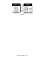
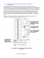
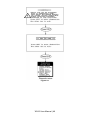
3.1.7 Optional Clock / Printer Interface Board
#10-0229
When equipped with the 10-0229 Clock / Printer Interface option, shown in Figure 3.8,
the WX16 Controller is capable of automatically printing time & date stamped alarm
events to a 24 PIN dot matrix printer such as the Panasonic KX-P1131. The cable
interface between the WX16 and the KX-P1131 may be either parallel or serial.
Parallel interfaces only allow 6 feet of separation, while the RS-232 serial interface
allows up to 50 feet. Distances up to 4000 feet may be obtained using the 10-0229
printer interface option’s RS-422 port but require an additional tri-port RS-422 / RS-232
converter at the printer end of the cable.
The 10-0229 Printer Interface may also be connected to a PC running HyperTerminal
or other communications software as an alternative to hard copy printing of the data.
Printer / PC cable schematics are shown in Figure 3.8. Printer settings for serial
interfaces are 9600 baud, 8 data bits, no parity and one stop bit. Communications
software settings are 9600 baud, 8 data bits, no parity, one stop bit and FlowControl =
Hardware. Printer diagnostic red LED’s indicate printer faults such as out of paper,
overflowed buffer or loss of communications. Green LEDs flicker to confirm good
communications between the WX16 and printer during print attempts.
Examples of printed alarm events are shown below. The format of each event, from left
to right, is DATE, TIME, 16 character ASCII channel ID from the WX16, WX16 channel
#, alarm #, IN or OUT status. A buffer in the WX16 retains the most recent 30 – 35
printed events. It is possible to dump the entire buffer to the printer from the menu
shown in Figure 3.9. This is useful if printer problems have occurred causing missed
printouts.
05/22/03 08:21:00 Storage Tank 103 Chnl 1 Alarm 2 IN
05/22/03 08:21:01 Storage Tank 103 Chnl 1 Alarm 2 OUT
05/22/03 09:12:01 Storage Tank 103 Chnl 13 Alarm 1 IN
05/22/03 09:13:00 Fuel A Flow Chnl 9 Alarm 1 IN
05/22/03 09:13:05 Storage Tank 103 Chnl 1 FAULT IN
05/22/03 09:13:05 Fuel Dock Chnl 2 FAULT IN
05/22/03 09:40:10 Storage Tank 103 Chnl 13 Alarm 2 IN
05/22/03 09:40:14 Fuel Dock Chnl 2 FAULT OUT
05/22/03 09:40:14 Trans Pump 103 Chnl 3 FAULT OUT
05/22/03 09:40:14 Storage Tank 103 Chnl 1 FAULT OUT
05/20/03 11:53:37 Fuel A Flow Chnl 9 Alarm 1 OUT
WX16 User Manual | 42
Figure 3.8
3.1.7.1 Clock / Printer System Setup Menu
Detection of the 10-0229 on the I2C bus causes the Clock / Printer System Setup
menu item to appear. Selecting it and pressing EDIT brings up the menu shown at right
in Figure 3.9. Date / Time menu entries allow setting of correct local time and date.
The ALARM PRINT ON/OFF entry allows printing to be discontinued if turned to OFF.
PORT allows selection of RS-232, RS-422 or the parallel port. With only one port able
to be activated at a time. BUFFER DUMP allows immediate printing of all the 30-35
stored events. PRINT CONFIG allows immediate printing of all channel variables such
as channel ID’s, Engineering Units, etc. PRINTER READY / ERROR indicates the
functional status of the printer.
WX16 User Manual | 43
Figure 3.9
3.1.8 Optional 24 VDC 150 Watt Power Supply
The WX16 Controller may be powered from 10-30 VDC. However, many applications
require 24 VDC power for the monitors or transmitters providing inputs to the WX16. A
150 watt AC / DC power supply may be included for these applications (115 VAC or
230 VAC selected via slide switch). When ordered from the factory, it is pre-wired to
provide 24 VDC primary power for the WX16 controller as well as any transmitters or
monitors that may be connected by the end user.
Figure 3.10
WX16 User Manual | 44
SECTION - 4 .
4.0 System Diagnostics
A System Diagnostic Mode shown in Figures 4.1 and 4.2 may be entered during
normal operation from the Setup menu. The entry menu indicates firmware revision
and offers useful routines for testing front panel LED’s, relays, serial ports and analog
I/O. It is exited manually by pressing NEXT and automatically if no keys are pressed
for 5 minutes. It is very important to understand that CHANNEL INPUT DATA IS NOT
PROCESSED DURING THE DIAGNOSTICS MODE. It is possible to miss
important input values while utilizing this mode and appropriate safeguards
should be in place. However, the Diagnostics Mode can prove invaluable
when testing I/O since relays and analog outputs may be stimulated without driving
inputs to precise levels.
WX16 User Manual | 45
Figure 4.1
WX16 User Manual | 46
Figure 4.2
WX16 User Manual | 47
WX16 User Manual | 48
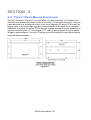
SECTION - 5 .
5.0 ModBus RS-485 Ports
The WX16 is equipped with Master (COMM 1), and Slave (COMM 2), ModBus RTU
ports. Port configurations are described in sections 2.2 and 2.3 of this manual. Section
5.0 defines register locations of data available via the WX16 slave port.
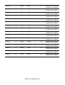
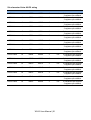
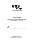
5.1 ModBus Slave Register Locations
The following tables describe the WX16’s ModBus slave database. Any portion of this
data may be read by a ModBus master device such as a PC, PLC or DCS. Since the
ModBus port is RS-485, many WX16s may be multi-dropped onto the same cable.
Memory Integer ASCII
Notes: ASCII may be read 2 characters at a time or in strings using a multiple register read.
Sixteen character channel tag name
Type
Channel
First
Last
Read FC Write FC
Notes
Channel Tag
1
40401
40408
3
n/a
2 characters per register
Channel Tag
2
40409
40416
3
n/a
2 characters per register
Channel Tag
3
40417
40424
3
n/a
2 characters per register
Channel Tag
4
40425
40432
3
n/a
2 characters per register
Channel Tag
5
40433
40440
3
n/a
2 characters per register
Channel Tag
6
40441
40448
3
n/a
2 characters per register
Channel Tag
7
40449
40456
3
n/a
2 characters per register
Channel Tag
8
40457
40464
3
n/a
2 characters per register
Channel Tag
9
40465
40472
3
n/a
2 characters per register
Channel Tag
10
40473
40480
3
n/a
2 characters per register
Channel Tag
11
40481
40488
3
n/a
2 characters per register
Channel Tag
12
40489
40496
3
n/a
2 characters per register
Channel Tag
13
40497
40504
3
n/a
2 characters per register
Channel Tag
14
40505
40512
3
n/a
2 characters per register
Channel Tag
15
40513
40520
3
n/a
2 characters per register
Channel Tag
16
40521
40528
3
n/a
2 characters per register
Six character Eunits Tag
Type
Channel
First
Last
Read FC Write FC
WX16 User Manual | 49
Notes
EUNITS
1
40529
40531
3
n/a
2 characters per register;
3 registers per channel
EUNITS
2
40532
40534
3
n/a
2 characters per register
3 registers per channel
EUNITS
3
40535
40537
3
n/a
2 characters per register
3 registers per channel
EUNITS
4
40538
40540
3
n/a
2 characters per register;
3 registers per channel
EUNITS
5
40541
40543
3
n/a
2 characters per register;
3 registers per channel
EUNITS
6
40544
40546
3
n/a
2 characters per register;
3 registers per channel
EUNITS
7
40547
40549
3
n/a
2 characters per register;
3 registers per channel
EUNITS
8
40550
40552
3
n/a
2 characters per register;
3 registers per channel
EUNITS
9
40553
40555
3
n/a
2 characters per register;
3 registers per channel
EUNITS
10
40556
40558
3
n/a
2 characters per register;
3 registers per channel
EUNITS
11
40559
40561
3
n/a
2 characters per register;
3 registers per channel
EUNITS
12
40562
40564
3
n/a
2 characters per register;
3 registers per channel
EUNITS
13
40565
40567
3
n/a
2 characters per register;
3 registers per channel
EUNITS
14
40568
40570
3
n/a
2 characters per register;
3 registers per channel
EUNITS
15
40571
40573
3
n/a
2 characters per register;
3 registers per channel
EUNITS
16
40574
40576
3
n/a
2 characters per register;
3 registers per channel
WX16 User Manual | 50
Six character Value ASCII string
Type
Channel
First
Last
ASCII Value
1
40577
40579
Read FC Write FC
3
n/a
2 characters per register;
3 registers per channel
ASCII Value
2
40580
40582
3
n/a
2 characters per register
3 registers per channel
ASCII Value
3
40583
40585
3
n/a
2 characters per register
3 registers per channel
ASCII Value
4
40586
40588
3
n/a
2 characters per register
3 registers per channel
ASCII Value
5
40589
40591
3
n/a
2 characters per register
3 registers per channel
ASCII Value
6
40592
40594
3
n/a
2 characters per register
3 registers per channel
ASCII Value
7
40595
40597
3
n/a
2 characters per register
3 registers per channel
ASCII Value
8
40598
40600
3
n/a
2 characters per register
3 registers per channel
ASCII Value
9
40601
40603
3
n/a
2 characters per register;
3 registers per channel
ASCII Value
10
40604
40606
3
n/a
2 characters per register
3 registers per channel
ASCII Value
11
40607
40609
3
n/a
2 characters per register
3 registers per channel
ASCII Value
12
40610
40612
3
n/a
2 characters per register
3 registers per channel
ASCII Value
13
40613
40615
3
n/a
2 characters per register
3 registers per channel
ASCII Value
14
40616
40618
3
n/a
2 characters per register
3 registers per channel
ASCII Value
15
40619
40621
3
n/a
2 characters per register
3 registers per channel
ASCII Value
16
40622
40624
3
n/a
2 characters per register
3 registers per channel
WX16 User Manual | 51
Notes
Memory Floating Point
Notes: Returned as 15 bit 2s complement with ±5% over/under range applied. Therefore, this must be
considered when scaling values to be displayed at the ModBus master. The following equation may be
used to determine a value for display.
Display Value = MODBUS Value [ (Span Value –Zero Value) 1.1] + {Zero Value – [(Span Value – Zero Value) .05]}
32767
Type
Channel
Channel Value 1-16
First
Last
33001-16
n/a
Read FC Write FC
4
n/a
Notes
15bit 2s complement
w/±5% over/under range
Analog Output
Notes: 12 bit integer for Channel Reading value = 800 counts = zero value, 4000 counts = 100% value.
Type
Channel
Reading
Channel
First
Last
1-16
31001
31016
Read FC Write FC
4
Notes
n/a
12bit integer
Channel Status words contain configuration and status bits for a channel. They are as follows:
Type
Channel
Channel Status 1-16
First
Last
31017
31032
Read FC Write FC
4
Notes
n/a
16bit integer
(see bit by bit definition below)
Alarm 1 Trip
Alarm 1 Horn Drive
Alarm 3 Type
Alarm 2 Horn Drive
Linearize
Alarm 3 Trip
Input Marker
Channel Disable
Controller Channel In Cal
ModBus Data Type
reserved
reserved
Alarm 1 Latch
Alarm 2 Latch
Alarm 3 Latch
Alarm 2 Trip
bit0
bit1
bit2
bit3
bit4
bit5
bit6
bit7
bit8
bit9
bit10
bit11
bit12
bit13
bit14
bit15
1 = Low
1 = On
1 = Level
1 = On
1 = On
1 = Low
1 = Input Marker Detected
1 = Disabled
1 = Local Cal Mode
1 = 4 byte float
reserved
reserved
1 = Latching
1 = Latching
1 = Latching
1 = Low
0 = High
0 = Off
0 = Fault
0 = Off
0 = Off
0 = High
0 = Normal Mode
0 = Enabled
0 = Normal Mode
0 = 2 byte integer
reserved
reserved
0 = Non latching
0 = Non latching
0 = Non latching
0 = High
Alarm status words are bits packed into 16 bit integer where lsb = channel 1 alarm status and msb = channel 16
alarm status.
Alarm status (bit = 1 indicates alarm is active)
Type
Channel
Alarm 1 Status 1-16
First
Last
31033
n/a
Read FC Write FC
4
WX16 User Manual | 52
n/a
Notes
packed 16bit integer
Alarm 2 Status 1-16
31034
n/a
4
n/a
packed 16bit integer
Alarm 3 Status 1-16
31035
n/a
4
n/a
packed 16bit integer
*Relay Status
31036
n/a
4
n/a
packed 16bit integer
n/a
*Note: Common Relay status bits (register 31036) are as follows.
Relay 1= bit0.
Relay 2= bit1
Fault Relay = bit2
Horn Relay = bit3
Type
Channel
First
Last
Cal Status
1-16
31037
n/a
Read FC Write FC
4
n/a
packed 16bit integer
Notes
Trend Interval
Timer
1-16
31038
n/a
4
n/a
16bit integer
(Time in Seconds)
Fault Status
1-16
31039
n/a
4
n/a
packed 16bit integer
Alarm LED flashing status
(bit = 1 indicates LED is flashing; “Acknowledge” clears all to 0):
Type
First
Last
Alarm 1 Status 1-16
Channel
31049
n/a
4
n/a
packed 16bit integer
Alarm 2 Status 1-16
31050
n/a
4
n/a
packed 16bit integer
Alarm 3 Status 1-16
31051
n/a
4
n/a
packed 16bit integer
Common
LED Status
31052
n/a
4
n/a
packed 16bit integer
1-16
Read FC Write FC
Notes
LCD Display Screen Displayed Integer
Type
LCD Screen
Channel
First
Last
n/a
31053
n/a
Read FC Write FC
4
WX16 User Manual | 53
n/a
Notes
8bit integer
Sensor Life
Type
Channel
First
Last
Sensor Life
1
31065
n/a
Read FC Write FC
4
n/a
Signed 16bit integer
Notes
Sensor Life
2
31066
n/a
4
n/a
Signed 16bit integer
Sensor Life
3
31067
n/a
4
n/a
Signed 16bit integer
Sensor Life
4
31068
n/a
4
n/a
Signed 16bit integer
Sensor Life
5
31069
n/a
4
n/a
Signed 16bit integer
Sensor Life
6
31070
n/a
4
n/a
Signed 16bit integer
Sensor Life
7
31071
n/a
4
n/a
Signed 16bit integer
Sensor Life
8
31072
n/a
4
n/a
Signed 16bit integer
Sensor Life
9
31073
n/a
4
n/a
Signed 16bit integer
Sensor Life
10
31074
n/a
4
n/a
Signed 16bit integer
Sensor Life
11
31075
n/a
4
n/a
Signed 16bit integer
Sensor Life
12
31076
n/a
4
n/a
Signed 16bit integer
Sensor Life
13
31077
n/a
4
n/a
Signed 16bit integer
Sensor Life
14
31078
n/a
4
n/a
Signed 16bit integer
Sensor Life
15
31079
n/a
4
n/a
Signed 16bit integer
Sensor Life
16
31080
n/a
4
n/a
Signed 16bit integer
*Note: -2 = Disabled, -1 = CAL Required, 0-100 = Sensor Life
Coils
Notes: Set this coil to issue an alarm “Acknowledge” via ModBus (see “Echo Ack” in section 2.3.4).
Type
Alarm Reset
Channel
First
Last
n/a
2001
n/a
Read FC Write FC
n/a
WX16 User Manual | 54
5
Notes
write 0xff to
high byte to set
Memory Discretes
Notes: May be read as single discrete or packed with multiple register read.
Type
Chnl Alarm 1
Type
Chnl Alarm 2
Type
Chnl Alarm 3
Channel
First
Last
1-16
12001-16
n/a
Channel
First
Last
1-16
12017-32
n/a
Channel
First
Last
1-16
12033-48
n/a
Read FC Write FC
2
n/a
Read FC Write FC
2
n/a
Read FC Write FC
2
n/a
Notes
discrete, may be packed
Notes
discrete, may be packed
Notes
discrete, may be packed
Memory Reals
Notes: Real value represents float value without the decimal point such as 123.4 is returned as 1234. Decimal
devisor is returned as 1, 10, 100, or 1000 for decimal position of 1, 2, 3, or 4, where 123.4 would return
the value 10.
Type
Channel
First
Last
Zero Real
1-16
41001-16
n/a
Read FC Write FC
3
n/a
zero real
w/o decimal point
Zero DP
1-16
41017-32
n/a
3
n/a
zero real divisor
Span Real
1-16
41033-48
n/a
3
n/a
span real
w/o decimal point
Span DP
1-16
41049-64
n/a
3
n/a
span real divisor
Alarm 1 Real
1-16
41065-80
n/a
3
n/a
alarm 1 real
w/o decimal point
Alarm 1 DP
1-16
41081-96
n/a
3
n/a
alarm 1 real divisor
Alarm 2 Real
1-16
41097-112
n/a
3
n/a
alarm 2 real
w/o decimal point
Alarm 2 DP
1-16
41113-28
n/a
3
n/a
alarm 2 real divisor
Alarm 3 Real
1-16
41129-44
n/a
3
n/a
alarm 3 real
w/o decimal point
Alarm 3 DP
1-16
41145-60
n/a
3
n/a
alarm 3 real divisor
Fault Real
1-16
41161-76
n/a
3
n/a
alarm 3 real
w/o decimal point
Fault DP
1-16
41177-92
n/a
3
n/a
alarm 3 real divisor
WX16 User Manual | 55
Notes
24-Hour Trend Database
The 24 hour MAX, MIN and AVERAGE trend data may be retrieved over the ModBus serial interface. Each
channel consists of 240 MAX, MIN and AVERAGE values, or, one value for every 1/10 hour (6 minutes). Since
there are 16 channels this database equals 3,840 registers in addresses 33017-36857. Due to the large size,
MAX, MIN or AVERAGE values may only be retrieved one at a time. To improve bandwidth, the master may
retrieve the database in blocks of 120 registers at a time (one half of a channel’s data). The C1 only updates
these 3,840 registers upon receiving an update command from the ModBus master.
Type
Channel
First
Last
Read FC Write FC
Notes
Update MIN
n/a
2065
n/a
n/a
5
Moves 24-hour MIN data
trend to trend data base
Update AVG.
n/a
2066
n/a
n/a
5
Moves 24-hour MIN data
trend to trend data base
Update MAX
n/a
2067
n/a
n/a
5
Moves 24-hour AVG data
trend to trend data base
This update requires several seconds. Therefore, a data ready register is available to notify the master upon
completion.
Type
Channel
First
Last
Read FC Write FC
Notes
MIN Ready
n/a
12065
n/a
2
n/a
0 = data ready;
1 = update in progress
AVG. Ready
n/a
12066
n/a
2
n/a
0 = data ready;
1 = update in progress
MAX Ready
n/a
12067
n/a
2
n/a
0 = data ready;
1 = update in progress
Trend database registers
Type
24-hr Trend
Channel
First
Last
1-16
33017
36857
Read FC Write FC
5
WX16 User Manual | 56
n/a
Notes
Transfers 24-hour trend
for MAX, MIN or AVG.
SECTION - 6 .
6.0 Panel / Rack Mount Enclosure
The WX16 shown in Figure 6.1 is a half-width 19” rack enclosure. It is supplied with
hardware that allows mounting in either a full-width 19” rack style cabinet or it may be
panel-mounted in a rectangular cutout. Only two 8-channel I/O option PCB’s such as
analog input or discrete relays may be mounted directly to the back of the enclosure.
Additional 8-channel I/O option PCB’s must be located external from the assembly on
2
another mounting plate. A 3-foot length of I C cable is also supplied for this purpose.
Weight is approximately 7 pounds. Properly ground the enclosure and follow national
and local electrical codes.
Figure 6.1
WX16 User Manual | 57
6.1 NEMA 4X Wall Mount Fiberglass Enclosure
The WX16 shown in Figure 6.2 is a fiberglass NEMA 4X wall mount enclosure. Seven
8-channel I/O option PCB’s, such as analog input or discrete relays, may be mounted
inside this enclosure. It is suitable for mounting outdoors, but an above-mounted
weather deflector shield is recommended. Weight is approximately 17 pounds. Figure
6.3 provides important warning information concerning correct grounding procedures
for non-metallic enclosures. Conduit entries are not provided so installers may place
entries as needed. Bottom or lower side areas are recommended. Care must be taken
to avoid drilling into circuit boards mounted inside the enclosure. Properly ground the
enclosure and follow national and local electrical codes.
Figure 6.2
WX16 User Manual | 58
Figure 6.3
WX16 User Manual | 59
6.2 NEMA 4X Wall Mount 316 Stainless Steel
Enclosure
The WX16 shown in Figure 6.4 is a 316 stainless steel NEMA 4X wall mount
enclosure. Seven 8-channel I/O option PCB’s, such as analog input or discrete relays,
may be mounted inside this enclosure. It is suitable for mounting outdoors, but an
above-mounted weather deflector shield is recommended. Weight is approximately 30
pounds. Conduit entries are not provided so installers may place entries as needed.
Bottom or lower side areas are recommended. Care must be taken to avoid drilling into
circuit boards mounted inside the enclosure. Properly ground the enclosure and follow
national and local electrical codes.
Figure 6.4
WX16 User Manual | 60
6.3 XP NEMA 7 Explosion-Proof Wall Mount
Enclosure
The WX16XP shown in Figure 6.5 is an aluminum NEMA 4X / 7 wall mount enclosure
designed for mounting into DIV 1&2 Groups B,C,D potentially hazardous areas.
Eleven, 8 channel I/O option PCB’s, such as analog inputs or discrete relays, may be
mounted inside this enclosure. It is suitable for mounting outdoors, but an abovemounted weather deflector shield is recommended. Weight is approximately 110
pounds. Properly ground the enclosure and follow national and local electrical codes.
Figure 6.5
6.4 Main I/O & Option PCB Footprint Dimensions
WX16 controllers have virtually unlimited possibilities for configuration of options such
as analog I/O, discrete relays, printer interface and others. All WX16 enclosure styles
require the Main I/O PCB (Figure 3.1) but also support the mounting of additional
option PCB’s as described below:
WX16PM Panel / Rack Mount supports 2 option positions as standard and 4
more with the 10-0180 expansion plate (since in panel / rack mount
installations 10-0180’s must be mounted in user space behind panels or
inside racks, multiple 10-0180’s may be incorporated to support the required
option positions).
WX16 User Manual | 61
WX16N4 & WX16SS NEMA 4X Wall Mount supports 3 option positions as
standard and 4 more with the 10-0180 expansion plate. If more than 7 option
positions are required, the 10-0178 NEMA 4X wall mount option enclosure
supporting 8 positions may be added.
WX16XP NEMA 7 Wall Mount supports 5 option positions as standard and 3
more with the 10-0181 expansion plate.
Figure 6.6 provides Main I/O and option PCB dimensions.
Figure 6.6
WX16 User Manual | 62
SECTION - 7 .
7.0 Adding The “Wireless” Radio Kit Option
WX16 master / slave serial ports may be connected to a FHSS (Frequency Hopping
Spread Spectrum) wireless radio modem shown in Figure 7.1. There are two different
frequency options offered, 900 MHz and 2.4 GHz. 900 MHz is available in a single port
modem (10-0364) or dual port modem (10-0365). 2.4 GHz is also available in a single
port (10-0357) or dual port modem (10-0358). The dual port radio modems have two
radio modules installed and can be used to receive and transmit data simultaneously.
The radio kit options allow three separate modes of wireless operation. These are
“Wireless Receiver” (section 7.2) accepting data from OLCT 200 sensor transmitters,
“Wireless ModBus Slave” (section 7.3) providing data to a ModBus master (master
side of network requires additional radio), and “Wireless ModBus Master” (section 7.4)
accepting wireless data from ModBus slaves (slaves side of network requires
additional radio). “Wireless Receiver” and “Wireless ModBus Master” modes require
the radio be connected to the WX16’s RS-485 master port and “Wireless ModBus
Slave” mode connects it to the RS-485 slave port (Figure 3.1). It is important to
remember RADIO SETUP functions described in section 7.1 may only be performed
with the radio connected to the master port.
Each transceiver on a wireless network must have its RADIO SETUP menus
configured to share the same hopping channel (0-32) and System ID (0-255) to
communicate. All WX-series wireless transceivers utilize a Server-Client network
where Clients synchronize their hopping to the Server. The Server transmits a beacon
at the beginning of every hop (50 times per second). Client transceivers listen for this
beacon, and upon hearing it, will indicate InRange with the LED on the radio modem
board and synchronize their hopping with the Server. Each network should consist of
only one Server. There should never be two servers on the same RF Channel number
in the same coverage area, as the interference between the two servers will severely
hinder RF communications. The Server must be in a powered location (as opposed to
a battery-powered OLCT 200 utilizing a “sleep” mode) and Servers typically should be
centrally located since all Clients must receive the beacon in order to communicate.
WX16 User Manual | 63
2.4 GHz Radio Modem
900 MHz Radio Modem
Note:
10-0357 Has One Radio Module Installed
10-0358 Has Two Radio Modules Installed
Note:
10-0364 Has One Radio Module Installed
10-0365 Has Two Radio Modules Installed
Figure 7.1
7.1 Radio Setup Menu
Radio modules must be connected to the WX16’s master port for RADIO SETUP.
Pressing the EDIT key with the arrow pointing to the Radio Setup menu brings the
RADIO CONFIG menus to the screen (right side of Figure 7.2).
Hop Channel may be set from 1-32 using the WX16 keypad and assigns the
pseudo-random radio frequency hopping pattern. A transceiver will not go
InRange of or communicate with a transceiver operating on a different Hop
Channel.
System ID may be set from 1-255 using the WX16 keypad and is similar to a
password character or network number and makes network eavesdropping
more difficult. A transceiver will not go in range of or communicate with a
transceiver operating on a different System ID.
Mode may be set for CLIENT or SERVER. For a single WX16 communicating
to up to sixteen battery-powered OLCT 200 transceivers, Mode must =
Server. To prolong battery life, OLCT 200’s sleep most of the time and
therefore may not be Servers. If an application calls for multiple WX16
locations, only one may be set for Server and all others must be Clients. This
single Server transmits a beacon that all of the network’s Clients synchronize
to. ONLY ONE SERVER PER NETWORK.
WX16 User Manual | 64
Figure 7.2
7.2 Wireless Receiver Mode
Wireless Receiver mode is exclusively for wireless communication to Oldham’s OLCT
200 wireless sensor transmitters (See www.oldhamgas.com for more details). In
Receiver mode, the radio connects to the WX16’s master port and receives input data
from up to sixteen OLCT 200 sensor transmitters. Wired and wireless inputs may be
mixed between the WX16’s sixteen channels, so it is possible to also accept wired
signals from analog input option PCB’s described in section 3.1.
Use the WIRELESS RF900 setting shown at center of Figure 7.3 ONLY FOR
COMMUNICATION TO OLCT 200 WIRELESS TRANSCEIVERS. See section 7.4 for
setting up wireless networks with other ModBus slave devices.
OLCT 200’s transmit 200 counts for 0% and 1000 counts for 100% full scale readings
so Input Min/Max menu values should be 200 & 1000. The Remote ID menu entry
must match the Remote ID address setting in the OLCT 200 providing data to this
WX16 channel. Input Req is typically set to VALUE but also allows a BATT entry into
this field. Entering BATT causes the channel to display (and alarm) from battery
voltage levels at this OLCT 200. Voltage level of the 3.6 volt lithium battery in this
OLCT 200 is also displayed on this screen.
Figure 7.3
7.2.1 Radio Status Alarms - Wireless Receiver Mode
When an WX16 channel’s INPUT DATA FROM menu is set for WIRELESS RF900, in
addition to processing the OLCT 200’s 10-bit “counts” value, it also receives status bits
indicating Communications Error, Low Battery and Calibration.
WX16 User Manual | 65
Communications Error – Each channel’s 30-minute trend screens (Figure
7.4) are very useful for diagnosing wireless problems, since they indicate
amount of time since the most recent transmission was received. The down
arrow on top of the trend screen resets to far right each time a transmission is
received by that channel. When not in alarm, OLCT 200’s transmit each 5
minutes, so the arrow should never progress past the 5-minute interval. The
WX16 activates the channel’s FAULT alarm and indicates ComErr if no
transmission has been received in 18 consecutive minutes.
Low Battery status indicates the OLCT 200’s integral 3.6V lithium D cell (part
#10-0293) has dropped to below 3.3V and should be replaced very soon.
LoBatt is indicated on the WX16’s LCD readout and the Alarm 3 LED flashes.
Relays are not energized by low battery conditions. The actual battery voltage
of each OLCT 200 may be seen in the INPUT DATA FROM screen described
above in section 7.2.
Calibrations performed at the OLCT 200 force a transmission of 75 counts
(negative 15.62%) which may be indicated on the WX16’s LCD readout by In
Cal by using the “Marker Menu” described in section 2.2.4b. Alarms are
inhibited while the “Marker Value” of -15.62% is activated.
Figure 7.4
7.3 Wireless ModBus Slave Mode
Wireless MODBUS allows one or many WX16s to function as wireless ModBus slaves
by connecting their RS-485 ModBus slave ports to a radio modem. These wireless
networks require a ModBus master such as a DCS, HMI or another WX16 Sixteen
Channel Controller; also equipped with a radio modem. As in all WX-series wireless
networks, one transceiver must be designated as Server and all others as Clients. No
special configuration is required by the master or slave, since this is a standard
ModBus network. However, radios must have the same Hop Channel and System ID
settings to communicate. Radio modules may only be configured when connected to
the WX16’s master port. If it is necessary to modify Hop Channel and System ID
settings, the radio module may be temporarily connected to the WX16’s master port for
configuration then moved back to the slave port for operation.
WX16 User Manual | 66
The entire WX16 ModBus database, including registers and supported Function
Codes, is documented in section 5.1.
7.4 Wireless ModBus Master Mode
WX16 applications as a “Wireless ModBus master” are similar to the “Wireless
Receiver” mode described in section 7.2 and wiring to the radio modem is identical.
The radio setup menus described in section 7.1 may also be used for configuring hop
channel and system ID settings. The difference is each Channel’s INPUT DATA
FROM menu must be configured with the correct MODBUS values to match the slave
device instead of Wireless RF900. Wired and wireless inputs may be mixed between
the WX16’s sixteen channels so it is also possible to accept wired signals from analog
input option PCB’s described in section 3.1.
This is a popular application when the ModBus slave is another remote WX16 or
Oldham’s WX4 controller available with built in radio modem compatible with the WX16
Radio Kit. Other ModBus slave devices may also be converted to wireless by addition
of another Radio Kit at the slave’s location.
7.5 Antenna Selection
7.5.1 Dipole And Collinear Antennas
These antennas are connected to the radio via a length of coax cable. If the cable is
larger than 6mm diameter (1/4 inch), do not connect the cable directly to the radio
connection on the WX16 enclosure. Thick cables have large bending radii and
sideways force on the connector can cause a poor connection. Use a short flexible
pigtail (such as our 1000-2308) between the thick cable and the radio.
The polarity of these antennas is the same as the main axis, and they are normally
installed vertically. They can be mounted horizontally (horizontal polarity), however the
antenna at the other end of the wireless link would need to be mounted perfectly
parallel for optimum performance. This is very difficult to achieve over distance. If the
antenna is mounted vertically, it is only necessary to mount the other antennas
vertically for optimum “coupling” – this is easy to achieve.
Dipole and collinear antennas provide best performance when installed with at least 1
to 2 “wavelengths” clearance of walls or steelwork. The wavelength is based on the
frequency:
Wavelength in meters = 300 / frequency in MHz
Wavelength in feet = 1000 / frequency in MHz
Therefore, 900 MHz antennas require at least 2/3 meter (2 feet) and 2.4GHz 15 cm (6
inches). Antennas may be mounted with less clearance, but radiation will be reduced.
WX16 User Manual | 67
If the radio path is short, this won’t matter. It is important the antenna mounting bracket
be well connected to “earth” or “ground” for good lightning surge protection.
7.5.2 Yagi Antennas
Yagi antennas are directional along the central beam of the antenna. The folded
element is toward the back, and the antenna should be “pointed” in the direction of the
transmission. Yagis should also be mounted with at least 1 to 2 wavelengths of
clearance from other objects. The polarity of the antenna is the same as the direction
of the orthogonal elements. For example, if the elements are vertical, the Yagi
transmits with vertical polarity.
In networks spread over wide areas, it is common for a central unit to have an omnidirectional antenna and the remote units to have Yagi antennas. In this case, as the
omni-directional antenna will be mounted with vertical polarity, then the Yagi’s must
also have vertical polarity. Care needs to be taken to ensure the Yagi is aligned
correctly to achieve optimum performance.
Two Yagis can be used for a point-to-point link. In this case they can be mounted with
the elements horizontally to give horizontal polarity. There is a large degree of RF
isolation between horizontal and vertical polarity (approx –30dB), so this installation
method is a good idea if there is a large amount of interference from another system
close by transmitting vertical polarity.
An important mounting tip: If a Yagi has drainage holes in the dipole element, do not
mount the antenna with the drainage.
7.5.3 Mounting Near Other Antennas
Avoid mounting your network’s antenna near any other antenna even when the other
antenna is transmitting on a different radio band. High RF energy of the transmission
from a close antenna can “deafen” a receiver. This is a common cause of problems
with wireless systems.
Because antennas are designed to transmit parallel to the ground rather than up or
down, vertical separation between antennas is a lot more effective than horizontal
separation. If mounting near another antenna cannot be avoided, mounting it beneath
or above the other antenna is better than mounting beside it. Using different polarity to
the other antenna (if possible) will also help to isolate the RF coupling.
7.5.4 Coax Cables
If a coax cable connects to the antenna via connectors, it is very important to
weatherproof the connection using our 1000-2314 or equivalent sealing tape. Moisture
ingress into a coax cable connection is the most common cause of problems with
antenna installations. A three layer sealing process is recommended – an initial layer
of electrical PVC tape, followed by a second layer of self-vulcanizing weatherproofing
tape (1000-2314), with a final layer of electrical PVC tape.
WX16 User Manual | 68
Allowing a drip “U loop” of cable before the connection is also a good idea. The loop
allows water to drip off the bottom of the U instead of into the connection, reduces
installation strain and provides spare cable length in case later the original connectors
need to be removed, the cable cut back and new connectors fitted.
Avoid installing coax cables together in long parallel paths. Leakage from one cable to
another has a similar effect as mounting an antenna near another antenna.
7.6 Surge Protection & Grounding
Voltage surges can enter the WX16 via the antenna connection, power supply
connection, connections to other equipment and even the “earth” or “ground”
connection. Surges are electrical energy following a path to earth, and the best
protection is achieved by “draining” the surge energy to earth via an alternate path.
Wireless devices need to have a solid connection to earth via a ground stake or ground
grid if the soil has poor conductivity. Solid connection means a large capacity
conductor (not a small wire) with no coils or sharp bends. All other devices connected
to the WX16 need to be grounded to the same ground point. There can be significant
resistance between different ground points leading to very large voltage differences
during lightning activity. As many wireless units are damaged by earth potential surges
due to incorrect grounding as are damaged bydirect surge voltage.
It is very difficult to protect against direct lightning strikes, but the probability of a direct
strike at any one location is very small. Unfortunately, power line surges and
electromagnetic energy in the air can induce high voltage surges from lightning activity
several miles away.
7.6.1
Antenna Grounding
Electromagnetic energy in the air will be drained to ground via any and every earth
path. An earth path exists between the antenna and the WX16, and to protect against
damage, this earth path current must be kept as small as possible. This is achieved by
providing better alternate earth paths. It is important to ground the antenna to the same
ground point as the WX16. Antennas are normally mounted to a metal bracket that
should be grounded to the WX16 earth connection. Surge energy induced into the
antenna will be drained first by the mount’s ground connection, second by the outside
shield of the coax cable to the ground connection on the radio and third by the internal
conductor of the coax cable via the radio electronics. This third earth path causes
damage unless the other two paths provide a better earth connection allowing surge
energy to bypass the electronics.
When an antenna is located outside of a building and outside of an industrial plant
environment, external coax surge diverters are recommended to further minimize the
effect of surge current in the inner conductor of the coax cable.
WX16 User Manual | 69
Coax surge diverters have a gas-discharge element which breaks down in the
presence of high surge voltage and diverts any current directly to a ground connection.
A surge diverter is not normally required when the antenna is within a plant or factory
environment, as the plant steelwork provides multiple parallel ground paths and good
earthing will provide adequate protection without a surge diverter.
7.6.2 Connections to Other Equipment
Surges can enter the wireless unit from connected devices, via I/O, serial or Ethernet
connections. Other data devices connected to the wireless unit should be well
grounded to the same ground point as the wireless unit.
Special care needs to be taken where the connected data device is remote from the
wireless unit requiring a long data cable. As the data device and the wireless unit
cannot be connected to the same ground point, different earth potentials can exist
during surge conditions.
There is also the possibility of surge voltages being induced on long lengths of wire
from nearby power cables. Surge diverters can be fitted to the data cable to protect
against surges entering the wireless unit.
The same principle applies when the I/O device is not close to the wireless unit, thus,
the risk of surge increases. Surge diverters for I/O wiring are available to protect the
wireless unit
WX16 User Manual | 70
WX16 User Manual | 71
The Fixed Gas Detection Experts
EUROPEAN PLANT AND OFFICES
Z.I. Est – rue Orfila CS 20417 – 62027 Arras Cedex FRANCE
Tél: +33 (0)3 21 60 80 80 – Fax: +33 (0)3 21 60 80 00
Website: http://www.oldhamgas.com
AMERICAS
Tel: +1-713-559-9280
Fax: +1-281-292-2860
[email protected]
ASIA PACIFIC
Tel: +86-21-3127-6373
Fax: +86-21-3127-6365
[email protected]
EUROPE
Tel: +33-321-608-080
Fax: +33-321-608-000
[email protected]