1
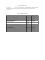
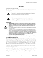
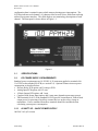
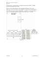
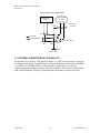
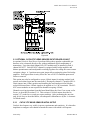
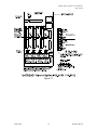
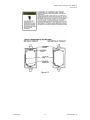
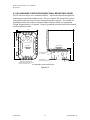
Model 7600 Controller Users Manual
Revision B
INSTRUCTION MANUAL
Model 7600, 6 CHANNEL CONTROLLER
(087-0018 REVISION B)
Modbus is a registered trademark of Modicon Corp.
Warning: Read & understand contents of this manual prior to
operation. Failure to do so could result in serious injury or death.
P.O. Box 569, Monroe, NC 28111
Phone: 800-247-7257 • FAX: 704-291-8330 • Web: www.scottsafety.com
REVISION HISTORY
Revision B
1/28/2011 Update Section 3, 5, added warranty, added part number
mapping, and add Revision History page. Added Scott Safety logos, and contact
information.
PART NUMBER MAPPING
Description
8 Channel Cat Bead Input PCB
Dual Channel Cat Bead Input PCB
60Watt Panel Mount Power Supply
Main I/O Controller PCB
Auxiliary Relay PCB
Panel/Rack Mount Enclosure
Wall Mount Enclosure, Fiberglass
Wall Mount Enclosure, Explosion Proof
6 Channel Relay PCB
I/O Controller PCB
Main I/O Controller PCB
Optional Analog Input PCB
Optional 4-20mA Analog Out PCB
P/N
10-0191
10-0192
10-0153
10-0142
10-0144
ST35PM/
10-0207
ST-35N4
ST-35XP
10-0196
10-0166
10-0213
10-0171
10-0152
Ordering P/N
093-0217
093-0297
093-0570
093-0216
093-0222
093-0330
093-0282
093-0284
093-0217
093-0216
093-0568
093-0214
093-0215
Model 7600 Controller Users Manual
Revision B
WARRANTY
Scott Safety, a Division of Scott Technologies, Inc. warrants to Buyer that at the time of delivery this product
will be free from defects in material and manufacture and will conform substantially to Scott Safety’s
applicable specifications. Scott Safety’s liability and Buyer’s remedy under this warranty are limited to the
repair or replacement, at Scott Safety’s option, of this Product or parts thereof returned to Seller at the
factory of manufacture and shown to Scott Safety’s reasonable satisfaction to have been defective; provided
that written notice of the defect shall have been given by Buyer to Scott Safety within one (1) year after the
date of this product by Scott Safety.
Scott Safety warrants to Buyer that it will convey good title to the Product. Scott Safety’s liability and Buyer’s
remedy under this warranty of title are limited to the removal of any title defects or, at the election of Scott
Safety, to the replacement of this Product or parts thereof that are defective in title.
The warranty set forth in paragraph 1 does not apply to parts the Operating Instructions designate as having
a limited shelf-life or as being expended in normal use.
THE FOREGOING WARRANTIES ARE EXCLUSIVE AND ARE GIVEN AND ACCEPTED IN LIEU OF (i)
ANY AND ALL OTHER WARRANTIES, EXPRESS OR IMPLIED, INCLUDING WITHOUT LIMITATION THE
IMPLIED WARRANTIES OF MERCHANTABILITY AND FITNESS FOR A PARTICULAR PURPOSE; AND
(ii) ANY OBLIGATION, LIABILITY, RIGHT, CLAIM OR REMEDY IN CONTRACT OR TORT, WHETHER OR
NOT ARISING FROM SCOTT SAFETY’S NEGLIGENCE, ACTUAL OR IMPLIED. The remedies of the
Buyer shall be limited to those provided herein to the exclusion of any and all other remedies including,
without limitation incidental or consequential damages. No agreement varying or extending the foregoing
warranties, remedies or this limitation will be binding upon Scott Safety unless in writing, signed by a duly
authorized officer of Scott Safety.
WARNING!
Because this instrument is used to detect and monitor materials and
conditions which are listed by OSHA or others as potentially hazardous to
personnel and property, the information in this manual must be fully
understood and utilized to ensure that the instrument is operating properly
and is both used and maintained in the proper manner by qualified
personnel. An instrument that is not properly calibrated, operated and
maintained by qualified personnel is likely to provide erroneous
information, which could prevent user awareness of a potentially
hazardous situation for the instrument user, other personnel and property.
If, after reading the information in this manual, the user has questions
regarding the operation, application or maintenance of the instrument,
supervisory or training assistance should be obtained before use. Factory
assistance is available by calling 800-247-7257.
© 2011 Scott Safety. SCOTT, the SCOTT SAFETY Logo, Scott Health and Safety, Model 7600, Model 7800 are
registered and/or unregistered marks of Scott Technologies, Inc. or its affiliates. All other trademarks are owned by their
respective owners.
SECTION 1 ........................................................................................................... 1
IMPORTANT SAFETY ISSUES .................................................................................................. 1
1.0
GENERAL DESCRIPTION ............................................................................................... 1
1.1
SPECIFICATIONS: .......................................................................................................... 2
1.2.
DC POWER SUPPLY REQUIREMENTS ........................................................................ 2
1.2.1
60 WATT AC – 24VDC POWER SUPPLY ................................................................... 2
1.2.2
AMBIENT TEMPERATURE RANGE............................................................................ 3
1.2.3
HUMIDITY RANGE ....................................................................................................... 3
1.2.4
ALTITUDE ..................................................................................................................... 3
1.2.5
HOUSINGS ................................................................................................................... 3
1.2.5a NON-INTRUSIVE MAGNETIC KEYPAD ...................................................................... 3
1.2.6
APPROVALS ................................................................................................................ 3
SECTION 2 ........................................................................................................... 3
2.0
BASIC OPERATION......................................................................................................... 3
2.1
SYSTEM CONFIGURATION ........................................................................................... 4
2.1.1
CHANGING VARIABLES USING THE KEYPAD ........................................................ 4
2.2
CHANNEL CONFIGURATION MENUS .......................................................................... 4
2.2.1
CAL MODE ................................................................................................................... 6
2.2.2
DECIMAL POINT RESOLUTION / ASCII FIELDS ....................................................... 7
2.2.3
MEASUREMENT RANGE ............................................................................................ 7
2.2.4
ALARM 1 / ALARM 2 / HORN RELAY SET-UP .......................................................... 8
2.2.5
ALARM 3 / FAIL ALARM.............................................................................................. 8
2.2.6
RANGE OF A-D COUNTS ............................................................................................ 9
2.2.7
MODBUS, SENSOR OR ANALOG INPUTS? ............................................................. 9
2.2.8
COPY DATA TO? ....................................................................................................... 10
2.3
SYSTEM CONFIGURATION MENUS ............................................................................ 10
2.3.1
AUTHORIZATION MODE ........................................................................................... 10
2.3.2
ACTIVATING CHANNELS / SCAN TIMER ................................................................ 11
2.3.3
ALARM 2 RELAY ACKNOWLEDGE ......................................................................... 11
2.3.4
ALARM SCAN PRIORITY .......................................................................................... 11
2.3.5
FAIL SAFE / NORMAL ALARMS............................................................................... 11
2.3.6
MASTER / SLAVE SERIAL PORT MENUS ............................................................... 12
SECTION 3 ......................................................................................................... 12
3.0
3.1
3.2
3.3
3.3.1
3.4
3.5
MAIN I/O INTERFACE PCB 093-0216 / 093-0568 ........................................................ 12
OPTIONAL ANALOG INPUT PCB 093-0214 ................................................................ 13
OPTIONAL DISCRETE RELAY PCB 093-0217 ............................................................ 16
OPTIONAL CATALYTIC BEAD SENSOR INPUT BOARD 093-0217 .......................... 17
CATALYTIC BEAD SENSOR INITIAL SETUP .......................................................... 17
OPTIONAL 4-20mA ANALOG OUTPUT BOARD 093-0215 ....................................... 20
OPTIONAL 24VDC 60 WATT POWER SUPPLY 093-0570 .......................................... 21
SECTION 4 ......................................................................................................... 22
4.0
SYSTEM DIAGNOSTICS ............................................................................................... 22
SECTION 5 ......................................................................................................... 24
5.0
5.1
MODBUS RS-485 PORTS.............................................................................................. 24
MODBUS SLAVE REGISTER LOCATIONS ................................................................. 25
SECTION 6 ......................................................................................................... 29
6.1
6.2
6.3
093-0330 PANEL / RACK MOUNT ENCLOSURE ........................................................ 29
093-0282 NEMA 4X WALL MOUNT ENCLOSURE ...................................................... 30
093-0284 NEMA 7 EXPLOSION-PROOF WALL MOUNT ENCLOSURE ..................... 32
Model 7600 Controller Users Manual
SECTION 1
IMPORTANT SAFETY ISSUES
The following symbols are used in this manual to alert the user of important instrument
operating issues:
!
This symbol is intended to alert the user to the presence of important
operating and maintenance (servicing) instructions.
This symbol is intended to alert the user to the presence of
dangerous voltage within the instrument enclosure that may be
sufficient magnitude to constitute a risk of electric shock.
!
WARNINGS:
• Shock Hazard - Disconnect or turn off power before servicing this instrument.
• NEMA 4X wall mount models should be fitted with a locking mechanism after
installation to prevent access to high voltages by unauthorized personnel (see
Figure 6.2).
• Use a properly rated CERTIFIED AC power (mains) cable installed as per local
or national codes
• A certified AC power (mains) disconnect or circuit breaker should be mounted
near the controller and installed following applicable local and national codes. If
a switch is used instead of a circuit breaker, a properly rate CERTIFIED fuse or
current limiter is required to installed as per local or national codes. Markings for
positions of the switch or breaker should state (I) for on and (O) for off.
• Clean only with a damp cloth without solvents.
• Equipment not used as prescribed within this manual may impair overall safety.
1.0 GENERAL DESCRIPTION
The Scott Safety, Model 7600, Six Channel Controller is designed to monitor, display,
and control alarm event switching for up to six sensor data points. Alarm features such
as ON and OFF delays, Alarm Acknowledge, and a dedicated horn relay make the well
suited for many critical multi-point monitoring applications. Sensor data may be input to
the by optional analog inputs or the standard Modbus® RTU master port. A Modbus
RTU slave port is also standard for sending data to PC’s, PLC’s, DCS’s, or even other
Controllers. Options such as analog I/O and discrete relays for each alarm are easily
added to the addressable I2C bus.
A high intensity LED display scans the six channel values at a programmable rate. These
12 alphanumeric digits indicate channel #, value with polarity, and six digits of
engineering units. A 2 line by 16 character LCD display provides operator interface to
Set-Up menus allowing configuration for a wide range of industrial applications. All
Scott Safety
1
087-0018 Rev B
Model 7600 Controller Users Manual
Revision B
configuration data is retained in non-volatile memory during power interruptions. The
LCD also indicates each channel’s 16 character Measurement Name field when not being
utilized for operator interface. This field displays user terminology descriptions of each
channel. The front panel is shown below in Figure 1.1.
Figure1.1
1.1
SPECIFICATIONS:
1.2.
DC POWER SUPPLY REQUIREMENTS
Standard power requirements are 10-30VDC @ 30 watts max applied to terminals 9 &
11 of TB2 on the standard I/O PCB (see section 3.0). Optional features increase power
consumption as described below:
• Discrete Relay PCB option; add 2 watts per PCB.
• Analog Input PCB option; add 1/2 watt.
• 4-20mA Output PCB option; add 1 watt.
• Catalytic Bead Sensor Input option; add 9 watts max (depends upon sensor power).
• TB2 terminals 10 & 12 of the standard I/O PCB provide a maximum of 500mA fused
output power for powering of auxiliary external devices such as relays, lamps or
transmitters. Power consumed from these terminals should be considered when
calculating system power consumption.
1.2.1 60 WATT AC – 24VDC POWER SUPPLY
100-240 VAC @2.0A max
Scott Safety
2
087-0018 Rev B
Model 7600 Controller Users Manual
Revision B
The 093-0570 60 watt power supply (Figure 3.9) is for powering the and up to 6
transmitters. A minimum of 5 watts per channel is available for powering of external
transmitters.
1.2.2 AMBIENT TEMPERATURE RANGE
-25 to 50 degrees C
1.2.3 HUMIDITY RANGE
0 TO 90% R. H. Non-Condensing.
1.2.4 ALTITUDE
Recommended up to 2000 meters
1.2.5 HOUSINGS
• General purpose panel mount weighing 7 lbs and including hardware for 19” rack
mounting (Figure 6.1).
• *NEMA 4X wall mount in fiberglass enclosure weighing 17 lbs (Figure 6.2).
• *NEMA 7 wall mount suitable for DIV 1&2 Groups B,C,D weighing 110 lbs (Figure
6.4).
*Includes non-intrusive magnetic keypad.
1.2.5a NON-INTRUSIVE MAGNETIC KEYPAD
The operator interface includes five front panel touch keys. A magnetic keypad option
offers these five keys with adjacent magnetic keys. This option is included as a standard
item when ordering NEMA 4X weather resistant or NEMA 7 explosion-proof enclosures.
It is useful in applications where it may be inconvenient to open the enclosure’s door to
access the touch keypad.
1.2.6 APPROVALS
CSA C22.2 No 1010.1 and ISA S82.02: EN55011 & EN61000 (CE Mark)
SECTION 2
2.0 BASIC OPERATION
Modes of operation are configured via the Operator Interface LCD display. After initial
power up, Normal mode operation is in effect causing both displays to scan active
channels (see Figure 2a). An alternative Alarm Priority mode may be configured that
only scans channels with alarms (see Figure 2b). Normal or Alarm Priority mode
operation may be halted by initiating the Manual mode, allowing unlimited duration
viewing of any channel (see Figure 2c). Manual mode is entered by pressing the
UP/DOWN keys simultaneously and using UP or DOWN to step to the desired channel.
A Set-Up mode is entered by pressing FUNCTION, scrolling to the desired menu tree
using the UP/DOWN keys, and pressing EDIT (see Figure 2d). This Set-Up mode may
be exited by pressing FUNCTION again. System critical alarm event switching of relays
and front panel alarm LED indicators is not affected by entering the Set-Up mode. An
Scott Safety
3
087-0018 Rev B
Model 7600 Controller Users Manual
Revision B
AUTHORIZATION MENU feature may be utilized to prevent malicious and accidental
tampering with alarm parameters.
0 PCTLEL
SCANNING ALARMS
Measurement Name
Measurement Name
Figure 2a (Normal)
Figure 2b (Alarm
MANUAL SCAN
F=NORM E=EDIT C1
UP/DN SELECTS CH
Measurement Name
Figure 2c (Manual)
Figure 2d (Set-Up)
2.1
SYSTEM CONFIGURATION
Each Controller requires configuration of system and channel variables upon initial
installation. After power up the controller will be in Normal mode or Alarm Priority
mode, depending upon how it was last powered down. Configuration of system and
channel variables requires entering the Set-Up mode by pressing FUNCTION, then
EDIT. A menu tree is provided for each of the 6 channels and another for system
variables. Select the tree to be entered by pressing the UP or DOWN buttons to scroll
through C1, C2, C3, C4, C5, C6 SY and press EDIT to enter the desired tree.
2.1.1 CHANGING VARIABLES USING THE KEYPAD
Each menu contains one or more entries to be configured. Some are simple YES/NO or
ON/OFF entries that are toggled by pressing the EDIT key. Others, such as the
Measurement Name and Engineering Units fields, may have many different ASCII
character possibilities. EDIT is used to modify variables within any menu. If the item
has only limited entries it toggles each time EDIT is pressed. If there are many possible
entries, EDIT begins a flashing cursor over the item and UP/DN scrolls through each
available entry. FUNCTION moves the flashing cursor to the next position within a
field. EDIT discontinues the flashing cursor and loads that entry into non-volatile
memory.
2.2
CHANNEL CONFIGURATION MENUS
Figure 2.2 shows the menu tree for configuring all channel variables on the left side of
the page. These only affect the specific channel that has been selected. The system menu
tree is shown on the right side of the page and is described in section 2.3.
Scott Safety
4
087-0018 Rev B
Model 7600 Controller Users Manual
Revision B
LCD OPERATOR INTERFACE MENU TREES
CHANNEL
MENUMENU
TREE (See
Section 2.2)
CHANNEL
TREE
SYSTEM MENU TREE (See Section 2.3)
0 PCTLEL
0 PCTLEL
Measurement Name
Measurement Name
FUNCTION
Section 2.0
FUNCTION
F=NORM E=EDIT C1
UP/DN SELECTS CH
UP/DN SELECTS CH
Section 2.2.1
EDIT
A/D Cnts = 905
EDIT
0 PCTLEL
XXXX UNLOCKED
Edit = Cal Zero
NAME: John Doe
EDIT
Edit = Cal Mode
UP/DOWN
UP/DOWN
Edit = Unity
Resets Cal Mode
Scan Timer 10s
Edit = Cal Span
Channels 1234--
Alarm 2 Relay
Section 2.3.3
50.0=Cal Span
F
u
n
c
t
i
o
n
UP/DOWN
EUNITS D.P. = 0
Section 2.2.2
UP/DOWN
0.000 PCTLEL
Enter Zero Value
UP/DOWN
Section 2.3.2
UP/DOWN
These menus appear only if SENSOR is
selected in the Input Data From: menu.
Measurement Name
Section 2.3.1
UP/DOWN
51 PCTLEL
UP/DOWN
0.000=Cal Zero
Acknowledge On
UP/DOWN
Alarm Scan
Section 2.3.4
Priority Off
UP/DOWN
Alarm 1 Relays
Normal
UP/DOWN
Section 2.2.3
100.0 PCTLEL
F
u
n
c
t
i
o
n
Section 2.0
F=NORM E=EDIT SY
Section 2.3.5
Alarm 2 Relays
Enter 100% Value
Fail Safe
UP/DOWN
UP/DOWN
Alarm1 Horn-Off
Slave Port
20.00 Latch?N H
9600 Baud Id 1
UP/DOWN
UP/DOWN
Alarm 1 Delays
Section 2.3.6
Master Port
On 0s Off 0m
9600 Baud
UP/DOWN
Section 2.2.4
UP/DOWN
Alarm2 Horn-Beep
40.00 Latch?Y H
UP/DOWN
Alarm 2 Delays
On 5s Off 5m
Note: Arrows = Key Strokes
UP/DOWN
-5.000 Latch?N F
Section 2.2.5
% Fault
UP/DOWN
905 800 4000
Section 2.2.6
Input Min
Max
UP/DOWN
Input Data From:
Analog 12 Bit
UP/DOWN
Section 2.2.7
RTU 1
This menu appears only if Modbus is
selected in the Input Data From: menu.
Alias 33001
UP/DOWN
Copy Data To:
Section 2.2.8
Channel 1
Figure 2.2
UP/DOWN
Scott Safety
5
087-0018 Rev B
Model 7600 Controller Users Manual
Revision B
2.2.1 CAL MODE
IMPORTANT! Figure 2.3 CAL MODE menus are only visible if the Input Data From:
menu, described in section 2.2.7, is set for Sensor.
Figure 2.3 illustrates how the CAL MODE menus function to allow push button
calibration of zero and span values. The correct zero and span set-point values must be
entered in order for the to make the correct adjustments. This feature should be utilized
only when there are no other zero/span controls within the monitoring system since it is
inappropriate to calibrate the same signal at more than one point. Therefore, if
calibration is to be performed at another transmitter or monitoring device, the CAL
MODE feature should not be used. Unintentional calibrations are reset by the UNITY
GAIN menu. Unity gain sets zero offset to 0 and span gain to 1.
A/D Cnts = 905
0 PCTLEL
Press Edit
Edit = Cal Zero
Edit = Cal Mode
Press Dn
Edit = Unity
Press Up/Dn
51 PCTLEL
Press Edit
Reading =Zero
Cal Set-Point
Press Edit
Edit = Cal Span
Resets Cal Mode
Press Dn
Press Edit
Offset = 0
Gain = 1
Press Func.
Reading =Span
Cal Set-Point
Returns to
Normal Mode*
0.000=Cal Zero
50.0=Cal Span
Figure 2.3
The bottom line of the top left menu in Figure 2.3 allows access to the calibration menus
by pressing EDIT. EDIT brings up the CAL ZERO display at the top right of Figure 2.3.
The top line displays the live channel value in engineering units and the bottom line
states: EDIT = ZERO CAL. It is important to understand that pressing EDIT now will
force this channel’s reading to match the zero set-point value previously entered.
Therefore, the sensor should have the appropriate stimulus to provide a response
approximating the zero set-point. Pressing the Up or Down buttons from the CAL ZERO
menu brings up the CAL SPAN menu. Pressing EDIT will cause a span adjustment
forcing the reading to match the span set-point value previously entered. Again, the
sensor should have the appropriate stimulus to provide a response approximating the span
set-point. For example, if an LEL combustible sensor is to be spanned with 50% LEL
Scott Safety
6
087-0018 Rev B
Model 7600 Controller Users Manual
Revision B
span gas, the span set-point must be 50%. If 45% LEL is to be used later, the span setpoint must be changed to 45% to match the span calibration gas.
2.2.2 DECIMAL POINT RESOLUTION / ASCII FIELDS
The Figure 2.4 menu sets the 6 character engineering unit and 16 character Measurement
Name ASCII fields. Only uppercase letters and numbers 0-9 may be displayed in the
engineering unit field since it is difficult to display lowercase letters on the large
alphanumeric LED readout. The Measurement Name field is displayed only on the LCD
and supports upper and lowercase letters along with many other symbols.
Resolution of channel values is also configured in this menu by setting the number digits
trailing the decimal point. Values are limited to a maximum of four digits and a polarity
sign. auto-ranging displays the highest resolution allowed by this decimal point entry.
For example, if three decimal points are entered and the range is 0 to 100ppm, the reading
will be 0.000 at 0ppm and 100.0 at 100ppm. However, this may be undesirable due to
the high resolution at zero unless the sensor’s output is extremely stable. If decimal
points are limited to one the 0ppm reading becomes 0.0 and the 100ppm reading remains
100.0. Resolution may be limited further by setting decimal points to 0. In the above
example, this causes 0ppm to display 0 and 100ppm to display 100.
EUNITS D.P. = 0
Measurement Name
Figure 2.4
2.2.3 MEASUREMENT RANGE
The menus shown in Figure 2.5a & 2.5b allow configuration of the measurement range
displayed on this channel. These menus work in conjunction with the A/D Counts menu
described in section 2.2.6 and normally match the range of the input signal’s engineering
units. For example, if a channel’s input is 4-20mA from a transmitter monitoring 0 to
10ppm chlorine, then the zero value should equal 0.000 and the 100% value equal 10.00.
The six ASCII engineering units previously entered are automatically displayed to the
right of the value as a reminder. The entire 4 digits must appear in this entry so trailing
0’s may appear here that are not displayed on the LED readout.
0.000 EUNITS
100.0 PCTLEL
Enter Zero Value
Enter 100% Value
Figure 2.5a
Scott Safety
Figure 2.5b
7
087-0018 Rev B
Model 7600 Controller Users Manual
Revision B
2.2.4 ALARM 1 / ALARM 2 / HORN RELAY SET-UP
The menus shown in Figure 2.6a & 2.6b allow configuration of ALARMS 1 & 2 and how
each affect the horn relay. There are two each of the menus in Figure 2.6 affecting
ALARM 1 identical to ALARM 2.
The AlarmX Horn-XXXX menu shown in Figure 2.6a may be set for Beep, Off, or On.
Beep causes the horn relay to pulse ON/OFF each second when the alarm is active. On
causes the horn relay to be continuous when the alarm is active. Off causes the alarm to
have no effect upon the horn relay. Discrete LED indicators on the front panel indicate
the status of each alarm and relay. Any new alarm event causes the associated LED to
flash until Alarm Reset occurs causing an acknowledged steady on condition. Operators
should recognize new alarms by a flashing LED. Alarm Reset also turns off the horn
relay until another new alarm occurs. The bottom line of this menu determines the
alarm’s trip-point value, latching or non-latching, and high or low trip. The trip-point is
entered in engineering units. After the Latch? icon, entering Y causes that alarm to
require a manual Alarm Reset to clear. Y latches this alarm group’s common relay, this
channel’s LED, and the optional discrete relay if so equipped. The far right character on
the bottom line may be set to H for high trip alarms or L for low trip alarms determining
if the alarm becomes active upon exceeding or falling below the trip-point.
Alarm1 Horn-Beep
Alarm 1 Delays
20.00 Latch?N H
On 5s Off 0m
Figure 2.6a
Figure 2.6b
The menus shown in Figure 2.6b allow entering ON and OFF time delays affecting how
long the trip-point must be exceeded before an alarm event transition occurs. ON delays
are limited to 10 seconds and OFF delays may be as long as 120 minutes. Delays are
useful in many applications for preventing nuisance alarms and unwanted cycling into
and out of alarm conditions.
2.2.5 ALARM 3 / FAIL ALARM
The discrete channel alarms identified as Alarm 3/Fail may be configured either as a 3rd
level alarm, or, as a Fail alarm providing notification that the input is out of range in the
negative direction. This is controlled by the menu shown in Figure 2.7. It is important to
understand that even though the discrete channel alarms may be set as Alarm 3 level
alarms, the common relay for this group is always a Fail alarm. The out of range
threshold for the channel is the most recent Fail trip point entered prior to changing the
menu to alarm 3. The following example describes how to configure both the Fail and
Alarm 3 trip points for a channel. If it is desired for the common Fail relay to trip as the
input falls below negative 10% of full scale, and the discrete alarms trip as the input
exceeds a level, the–10% Fail value must be entered first. Toggle the A/F character on
the right side of the top line to F and enter –10.00% into the value entry. Next, toggle the
A/F character back to A and enter the desired Alarm 3 trip level. The Fail value is
retained in memory although it no longer appears on the menu.
Scott Safety
8
087-0018 Rev B
Model 7600 Controller Users Manual
Revision B
-10.00 Latch?N F
% Fault
Figure 2.7
2.2.6 RANGE OF A-D COUNTS
The menu in Figure 2.8 defines what range of A-D (analog to digital) counts will provide
Measurement Range read out values entered previously in section 2.2.3. This menu entry
is determined by the A/D converter resolution of the channel’s input. For example, if the
input is a 12 bit Modbus® device with zero at 800 counts and 100% at 4000 counts, then
this menu’s MIN should be set at 800 and MAX at 4000. If communicating with the ’s
optional 12 bit Analog Input PCB the MIN should be 800 and the MAX 4000.
905 800 4000
Input Min Max
Figure 2.8
For questions what to enter in this menu, the variable on the left side of the top line
displays actual raw A/D counts currently being read by this channel. This may be
utilized to test the input device for what counts are provided for zero and 100% if these
values are unknown. Forcing the input device to read zero should provide the A/D counts
value needed to make this channel’s display also read zero. Likewise, forcing the input
device to read 100% should provide the A/D counts value needed to make the channel’s
display also read 100%.
2.2.7
MODBUS, SENSOR OR ANALOG INPUTS?
Each channel may be independently configured to accept input data from the Modbus
RS-485 master port, or, from an analog input card attached to the I2C bus. EDIT toggles
the Figure 2.9a menu between Modbus RTU, Analog or Sensor. Within each of these
possibilities are additional choices to accommodate the binary resolution of the input data
(8 bit, 10 bit, 12 bit etc.). With Modbus selected the menu shown in Figure 2.9b requests
the RTU # and the Alias register # location of the data to be retrieved from the RTU.
Alias register numbers define the location of the floating point variable representing the
input value.
Analog should be selected when the channel’s input comes from a transmitter or
monitoring device with a calibrated output such as 4-20mA. Sensor is identical to analog
except it activates the ’s Cal Mode feature. Problems may arise if calibrations are
performed in two places upon the same signal so Cal Mode menus are only visible when
Sensor is selected. The Sensor selection should only be used when the input originates
from a non-calibrated signal source such as the Catalytic Bead Sensor Input option
described in section 3.3. Applications such as this require the to be used as the
calibration point since the sensor signal has no zero and span adjustments.
Scott Safety
9
087-0018 Rev B
Model 7600 Controller Users Manual
Revision B
Input Data From:
RTU 1
Analog 12 bit
Alias 33001
Figure 2.9a
Figure 2.9b
2.2.8 COPY DATA TO?
This menu simplifies the Set-Up procedure by allowing similar channels to be copied
from one to another. For example, if all channels are identical except for the
Measurement Name entry, channel 1 could be configured first and copied to channels 2 –
6. Only Measurement Name would then need to be configured on channels 2 – 6. Use
EDIT to activate the cursor then UP/DN to select the channel to copy to. Press EDIT
once more to copy.
Copy Data To:
Channel 2
Figure 2.10
2.3 SYSTEM CONFIGURATION MENUS
Some items requiring configuration are not specific to each channel but affect the entire
system. These are located in the system menu tree shown in Figure 2.2 on the right side
of the page. System menus are accessed by pressing FUNCTION, then DOWN until the
SY icon appears in the upper right of the LCD readout, then EDIT.
2.3.1 AUTHORIZATION MODE
The system menu in Figure 2.11 allows locking variables that might prevent critical
alarm events if altered. Viewing menus is not denied but attempts to edit variables
displays a brief System Locked message on the LCD.
Authorized individuals locking the system should first enter a name, phone # or some sort
of contact information into the 10 digit field on the bottom line. To lock or unlock the
system the correct 4 digit authorization number must be entered into the XXXX field.
UP or DOWN then toggles the UNLOCKED message to LOCKED. It is important to
record the 4 digit code since the factory must be consulted if lost.
XXXX UNLOCKED
NAME: 4099257808
Figure 2.11
Scott Safety
10
087-0018 Rev B
Model 7600 Controller Users Manual
Revision B
2.3.2 ACTIVATING CHANNELS / SCAN TIMER
The system menu in Figure 2.12 allows configuration of scan time and inactive channels.
The scan timer entry on the top line of this menu sets how many seconds displays remain
on an active channel while scanning. This may be from 1 – 99 seconds. The Channels
entry on the bottom line determines what channels are active. A dash appears for inactive
channels as demonstrated in channels 5 & 6 below. Inactive channels are not displayed
and do not contribute to alarm events.
Scan Timer 10s
Channels 1234-Figure 2.12
2.3.3 ALARM 2 RELAY ACKNOWLEDGE
This menu allows the ALARM 2 common alarm relay to be acknowledged. This means
that while an alarm 2 event exists, the relay may be deactivated by an ALARM RESET.
This is useful for silencing audible devices while personnel work to correct the alarm
condition.
Alarm 2 Relay
Acknowledge On
Figure 2.13
2.3.4 ALARM SCAN PRIORITY
With the Alarm Scan Priority feature activated only channels with alarms are scanned by
the displays. If no alarms exist then all active channels are scanned. With only one
channel in alarm scanning halts on that channel.
Alarm Scan
Priority Off
Figure 2.14
2.3.5 FAIL SAFE / NORMAL ALARMS
These two menus allow ALARM 1 and ALARM 2 common and optional discrete relays
to be configured for fail safe or normal operation. Fail safe means alarm conditions force
the relay contacts to their power off, or shelf, state. Therefore, if the loses power the
contacts will indicate the alarm condition rather than a safe condition. The common
FAIL relay is always fail safe and is typically used to signal trouble conditions such as
power or signal loss.
Scott Safety
11
087-0018 Rev B
Model 7600 Controller Users Manual
Revision B
Alarm 1 Relays
Alarm 2 Relays
Fail Safe
Normal
Figure 2.15a
Figure 2.15b
2.3.6 MASTER / SLAVE SERIAL PORT MENUS
The final two menus in the system tree, shown in Figures 2.16a
6a & 2.16b, allow setting
baud rates for the master / slave Modbus serial ports. The RTU address of the slave port
is also entered here. This slave port may be used to transfer data to a host device such as
a PC, PLC or DCS. The slave port is addressable, allowing many controllers to be
connected to a single RS-485 cable. Section 5 of this manual provides important
information describing how to interface to the ’s Modbus slave port
Slave Port
Master Port
9600 Baud Id 1
9600 Baud
Figure 2.16a
Figure 2.16b
SECTION 3
3.0 MAIN I/O INTERFACE PCB 093-0216 / 093-0568
093-0216 and 093-0568 Main I/O Interface PCB’s are equivalent except the 093-0568
has ribbon cable connector J1 mounted on the back of the PCB. 093-0216’s are supplied
on all wall mount models while the 093-0568 is supplied only on the PM panel mount.
!
The most basic Controller requires only the I/O PCB shown in Figure 3.1 for interfacing
to field wiring. The primary power supply is applied to terminals 9 & 11 of TB2. This
may be from 10 – 30 VDC. WARNING! HIGH VOLTAGES SUCH AS 115
VAC APPLIED TO THESE TERMINALS MAY CAUSE SEVERE
DAMAGE! DC output terminals 10 & 12 on TB2 provide up to 500mA of output
power for powering remote devices such as lamps, transmitters etc.
This PCB includes both master (COMM 1) and slave (COMM 2) RS-485 Modbus ports,
5 amp form C relays for each common alarm event (A1, A2, FAULT/A3 & HORN), and
power supply I/O terminals. JP1 allows the RS-485 ports to be configured for 2 or 4 wire
operation. A 26 pin ribbon cable connects the I/O PCB to the CPU and Display nest
assembly. Two I2C bus connectors allow addition of optional functions such as analog
I/O and discrete alarm relays for each channel.
Horizontal jumpers installed in JP1 connect the RS-485 port’s RX & TX lines,
simplifying 2 wire daisy chains by providing additional terminals for incoming and
outgoing cables. For example, installing the 2 COM 1 jumpers connects screw terminals
1 & 5 and terminals 3 & 7. Socketed RS-485 terminating resistors R6 (COMM 1) and
R12 (COMM 2) are located on the MAIN I/O board. These resistors should be removed
Scott Safety
12
087-0018 Rev B
Model 7600 Controller Users Manual
Revision B
if communication wire lengths are very short (less than 25 feet), or, if the port is not at
the end of the communication line.
An optional Auxiliary Relays piggyback PCB (part 093-0222) may be added to the I/O
PCB via ribbon cable J4. These add another form C contact set to the common A1, A2
and HORN alarms. Auxiliary Relay contacts are available at the TB1 (AUX) terminals
shown in Figure 3.1.
Figure 3.1
3.1 OPTIONAL ANALOG INPUT PCB 093-0214
Many transmitters or sensors have analog output signals and the 10 bit Analog Input
PCB, shown in Figure 3.2, is available to accept these. TB1, with 24 positions, offers
four terminals per channel to distribute power and receive analog inputs. These are EXC
+ / - and HI / LO inputs. TB2, with only two positions, is for connecting the power
supply for powering external transmitters. SB1 and SB3 are solder bridge configuration
jumpers that determine the wiring between TB1 & TB2. Precision 100 ohm resistors (R1
– R6) between each channel’s IN LO and IN HI terminals are socketed termination
resistors for 4-20mA inputs. These may be removed if voltage inputs are to be applied.
EXC –, EXC + and IN LO terminals are bussed together as shown by the wiring
schematic in Figure 3.3. EXC + terminals are tied directly to TB2-2. EXC - terminals
are tied directly to TB2-1 when solder bridge jumper SB1 is in the “A” position. IN LO
terminals are tied to TB2-1 when SB1 is in the “B” position. With SB3 installed, all
EXC - terminals are tied to the chassis/earth ground. SB1 in the “A” position and SB3
installed are normal factory settings. This provides terminals for landing drain wires
from shielded cables and bussing allows transmitter power to be brought into the system
Scott Safety
13
087-0018 Rev B
Model 7600 Controller Users Manual
Revision B
at a single point. Transmitter power is available at each channel’s EXC + / IN LO
terminals and simplifies field wiring.
Figure 3.4 shows typical wiring to 3 wire transmitters and Figure 3.5 for 2 wire
transmitters. In rare cases when a 4 wire transmitter’s negative power terminal must be
isolated from the negative signal terminal, EXC - is available for carrying the negative
power. For such applications remove SB3 and move SB1 to the "A" position.
Figure 3.2
Scott Safety
14
087-0018 Rev B
Model 7600 Controller Users Manual
Revision B
3
7
11
15
19
23
EXC+’s
TB2
2
1
1
5
9
17
13
21
2
6
10
14
18
EXC-‘s
22
IN LO’s
A
B
SB1
SB3
TB1
ANALOG INPUT BUS
WIRING DIAGRAM
earth
Figure 3.3
Typical 3 Wire Transmitter Wiring
3 wire 4-20mA
transmitter
+24V Com Sig
24VDC Power
Supply
+
-
3 wire cable
w/ shield
shield
1
2
TB2
1
Field wiring
Internal PCB traces
3
4
2
A B
SB1
Typical, Ch1 shown
TB1
SB3
Earth
Figure 3.4
Scott Safety
15
087-0018 Rev B
Model 7600 Controller Users Manual
Revision B
Typical 2 Wire Transmitter Wiring
2 wire 4-20mA
transmitter
24VDC Power
Supply
+
-
+24V Sig
2 wire cable
w/ shield
shield
1
2
TB2
1
Field wiring
Internal PCB traces
3
4
2
A B
SB1
Typical, Ch1 shown
TB1
SB3
Earth
Figure 3.5
3.2 OPTIONAL DISCRETE RELAY PCB 093-0217
An optional Discrete Relay PCB, shown in Figure 3.5, adds six 5 amp form C relays per
six channel alarm group. Each PCB may be jumper configured to function for ALARM
1, ALARM 2 or ALARM 3/FAIL. Alarm groups, or zones, may be created by
connecting adjacent channels together using JP4 as shown. This creates an OR function
with selected channels; causing any alarm included in the zone to actuate all relays.
Scott Safety
16
087-0018 Rev B
Model 7600 Controller Users Manual
Revision B
Figure 3.6
3.3 OPTIONAL CATALYTIC BEAD SENSOR INPUT BOARD 093-0217
An optional Catalytic Bead Sensor Input board allows these popular combustible gas
detectors to be connected directly to the without additional signal conditioning or
transmitters. Up to three dual channel 093-0297 modules may be installed in each 8channel 093-0217. Each 093-0297 channel is equipped with a bridge amplifier and
balance potentiometer and an adjustable switching regulator for setting the correct sensor
excitation voltage. A 3 position coarse gain jumper allows setting the gain of the bridge
amplifier. Fault supervision circuitry forces the into a FAULT condition upon sensor
failure or removal.
This option may also be configured to accept 4-20mA inputs for mixing catalytic bead
sensors and current loops into the same board. Placing any channel’s 2 position LEL/420mA jumper into 4-20mA position and installing the associated precision 100 ohm
socketed resistor allows 4-20mA signals to be applied to it’s C & A terminals. The 0930297 sensor modules are not required for channels accepting 4-20mA.
Channels receiving input data from this board should have the Data From: menu set for
Sensor, as described in section 2.2.4. This activates Cal Mode menus described in
section 2.2.7 needed to zero and span sensor readings. After performing the one time
only Initial Setup as described below, all subsequent calibrations are by the ’s electronic
Cal Mode menus.
3.3.1 CATALYTIC BEAD SENSOR INITIAL SETUP
Catalytic bead sensors vary widely in power requirements and sensitivity. It is therefore
important to configure each channel to match the sensor with which it will operate.
Scott Safety
17
087-0018 Rev B
Model 7600 Controller Users Manual
Revision B
1.
Prior to connecting sensors, apply power to the system. Note this PCB requires
24VDC power be connected to its TB2 terminals 1 & 2 as shown in Figure 3.5.
Suitable fused power is available from the Main I/O board’s TB2 terminal 10 &
12 (see Figure 3.1). Measure the voltage between each channel’s A and R
terminals and set the Voltage Adjust potentiometers for the correct sensor
excitation voltage. This may range from 1.5 volts to 7.5 volts depending upon
sensor specifications. Sensors may be damaged by accidental over voltage
conditions. It is recommended the Voltage Adjust potentiometer screws be
covered by a dollop of RTV or similar material after completion of this
procedure to avoid accidental over voltage conditions.
2.
Remove system power and connect sensor wires to the R-C-A terminals. Reapply
system power and confirm correct voltage across each sensor’s A & R terminals.
Note: If sensor wires are long, it may be necessary to measure the excitation
voltage at the sensor end to compensate for I2R losses in the wiring.
3.
With the minus voltmeter lead on TB2-2 (common), connect the plus lead to the
channel’s test point. With zero air on that sensor, adjust it’s Balance
potentiometer for .4 volts at the test point.
4.
Apply 50% LEL combustible span gas to the sensor and allow the test point
voltage to stabilize. Two volts = 100% input to the A – D Converter and .4 volts
= 0%. Therefore, 1.2 volts = 50%. Place the 3 position Coarse LEL Gain jumper
into the position which reads between .8 volts and 1.2 volts on the test point with
50% LEL gas on the sensor. Gain settings for each jumper position are as
follows: no jumper = 1, LOW = 7, MED = 21, HI = 41. Multiple jumpers have
an additive affect upon gain, so the LOW and MED jumpers together provide a
gain of 28.
Initial setup is now complete and normally only requires repeating if a sensor is replaced.
Final calibration of this channel may now be performed using the ’s electronic Cal Mode
feature described in section 2.2.1.
Scott Safety
18
087-0018 Rev B
Model 7600 Controller Users Manual
Revision B
Figure 3.7
Scott Safety
19
087-0018 Rev B
Model 7600 Controller Users Manual
Revision B
3.4
OPTIONAL 4-20mA ANALOG OUTPUT BOARD 093-0215
An optional 10 bit 4-20mA analog output board, shown in Figure 3.7, may be connected
to the I2C bus. Each channel’s output will transmit 4mA for 0% readings and 20mA for
100% readings. Loop drive capability depends upon the level of the ’s primary DC
power supply. With at least 20 volts DC primary power they are capable of driving
20mA through a 750 ohm load. Outputs are self powered and DC power should not be
provided by the receiving device. This PCB requires 24VDC power be connected to it’s
TB2 terminals 1 & 2 as shown in Figure 3.7. Suitable power is available from the Main
I/O board’s TB2 terminal 10 & 12 (see Figure 3.1).
0010-1109 ASSY# 10-0152
ST-35 ANALOG OUTPUT BOARD
REV.A
TB2
24 VDC power for output
current loops must be
supplied through TB2.
Connect to Main I/O PCB
terminals 10 & 12 of TB2.
(I2C5)
J1
U8
J1 & J2 are interchangable I2C
connectors used to add option
PCB assemblies to the ST-71.
U7
J2
2.048V REF.
TP1
REF ADJ
R19
Ref. Adj. allows trimming voltage
on TP1. 2.048 volts provides
20mA (+1%) outputs with 100%
of full scale readings.
U9
U1
U2
U3
U4
U5
Q2
Q4
Q6
Q8
Q10
TB1
1
2
LO HI
CH1
3
4
LO HI
CH2
5
6
LO HI
CH3
7
8
LO HI
CH4
9
U6
Q12
10 11 12
LO HI
CH5
LO HI
CH6
4-20mA ANALOG OUTPUTS
Figure 3.8
Scott Safety
20
087-0018 Rev B
Model 7600 Controller Users Manual
Revision B
3.5 OPTIONAL 24VDC 60 WATT POWER SUPPLY 093-0570
The Controller may be powered from 10-30VDC or 18VAC from a step down isolation
transformer. However, many applications require 24VDC power to drive the monitors or
transmitters providing inputs to the . A 60 watt AC / DC power supply (Figure 3.9) may
be included for these applications. This supply has a universal 100VAC to 240VAC
input range and requires no modification between 115VAC and 220VAC installations.
When installed at the factory, it is pre-wired to provide 24VDC primary power for the
controller as well as any transmitters or monitors that may be connected by the end user.
Figure 3.9
Scott Safety
21
087-0018 Rev B
Model 7600 Controller Users Manual
Revision B
SECTION 4
4.0 SYSTEM DIAGNOSTICS
The restores configuration data from non-volatile memory each time power is applied.
During this several second long procedure the LCD operator interface flashes messages
stating firmware revision and what I2C options are connected. These messages are useful
indications of the status of options such as discrete relays, analog outputs and others.
A System Diagnostic Mode may also be entered while power is applied. This mode
offers menus, shown in Figure 4.1, for testing LED’s, relays and analog I/O. To enter
this mode press and hold the EDIT key while simultaneously pressing the UP/DOWN
keys. A brief error code message appears. Immediately press and hold the FUNCTION
key until a DIAGNOSTIC MODE message appears on the top line of the LCD readout.
UP/DOWN keys are used to move through the various testing procedures. Pressing
ALARM/RESET at any time will return the to the normal monitoring mode. With no
keys pressed for 5 minutes, the diagnostic mode times out and automatically returns to
the normal mode.
It is very important to understand that CHANNEL INPUT DATA IS
NOT PROCESSED DURING THE DIAGNOSTICS MODE. It is
possible to miss important input values while utilizing this mode and
!
appropriate safeguards should be in place. However, the Diagnostics Mode
can prove invaluable when testing I/O since relays and analog outputs may be stimulated
without driving inputs to precise levels.
Scott Safety
22
087-0018 Rev B
Model 7600 Controller Users Manual
Revision B
LCD SYSTEM DIAGNOSTIC MODE MENU TREES
MODES = UP/DOWN
EXIT =ALM RESET
Press Alm
reset
Returns to Normal Mode
Press Dn
LED DISPLAY TEST
Sequences test pattern across
LED alphanumeric display;
testing all segments
Press Dn
ANALOG OUT BOARD
Chl 1 50% OUTPUT
Cycles 50% (12mA) outputs
to each channel’s output (if
equipped)
Press Dn
ANALOG IN BOARD
Chl 1 CNTS 1234
Cycles channels and reads
raw A/D counts (if equipped)
Press Dn
ALARM X DISCRETE
Press Edit
Cycles discrete alarm LED’s &
discrete relays (if equipped)
Press Edit
Cycles common HORN,
ALARM 1, ALARM 2 &
FAULT relays.
Press Edit
Cycles all discrete front panel
alarm LED’s without tripping
relays
EDIT = TEST
Press Dn
COMMON RLY TEST
EDIT = TEST
Press Dn
ALARM LED TEST
EDIT = TEST
Figure 4.1
Scott Safety
23
087-0018 Rev B
Model 7600 Controller Users Manual
Revision B
SECTION 5
5.0
MODBUS RS-485 PORTS
The is equipped with Master (COMM 1), and Slave (COMM 2), modbus RTU ports.
Port configurations are described in sections 2.2 and 2.3 of this manual. Section 5.1
defines register locations of data available via the slave port.
Figure 5.1 shows how to wire multiple ’s into a Master / Slave configuration. It is very
important to understand that RS-485 is not a current loop. The drivers and receivers must
share a common ground. This is why “two-wire network” is a misnomer when applied to
RS-485 and a third 0V, or common wire, must also be run between devices that do not
already share the same DC power supply.
Figure 5.1
Scott Safety
24
087-0018 Rev B
Model 7600 Controller Users Manual
Revision B
5.1 MODBUS SLAVE REGISTER LOCATIONS
The following table describes the ’s modbus slave database. Any portion of this data may
be read by a modbus master device such as a PC, PLC or DCS. Since the modbus port is
RS-485, many ’s may also be multi-dropped onto the same cable.
MemoryIntAsciiRW
Notes: ASCII which may be read 2 characters at a time or in strings using a multiple register read.
Description
Alias
R/FC
W/FC
Type
---------------------------------------------------------------------------------------------------------------------Channel 1 tag
40401-40408
3
na
Ascii 2 characters/reg
Channel 2 tag
40409-40416
3
na
Ascii 2 characters/reg
Channel 3 tag
40417-40424
3
na
Ascii 2 characters/reg
Channel 4 tag
40425-40432
3
na
Ascii 2 characters/reg
Channel 5 tag
40433-40440
3
na
Ascii 2 characters/reg
Channel 6 tag
40441-40448
3
na
Ascii 2 characters/reg
Channel 1 eunits
Channel 2 eunits
Channel 3 eunits
Channel 4 eunits
Channel 5 eunits
Channel 6 eunits
40449-40451
40452-40454
40455-40457
40458-40460
40461-40463
40464-40466
3
3
3
3
3
3
na
na
na
na
na
na
Ascii 2 characters/reg
Ascii 2 characters/reg
Ascii 2 characters/reg
Ascii 2 characters/reg
Ascii 2 characters/reg
Ascii 2 characters/reg
Channel 1 Ascii value
40467-40469
3
na
Ascii 2 characters/reg
Channel 2 Ascii value
40470-40472
3
na
Ascii 2 characters/reg
Channel 3 Ascii value
40473-40475
3
na
Ascii 2 characters/reg
Channel 4 Ascii value
40476-40478
3
na
Ascii 2 characters/reg
Channel 5 Ascii value
40479-40481
3
na
Ascii 2 characters/reg
Channel 6 Ascii value
40482-40484
3
na
Ascii 2 characters/reg
---------------------------------------------------------------------------------------------------------------------MB_FltPtMemRO
Notes:
Returned as 15 bit 2s complement with +- 5% oner/underrange applied.
Description
Alias
R/FC
W/FC
Type
---------------------------------------------------------------------------------------------------------------------Channel 1 float value
33001
4
na
2s comp 15 bit integer
Channel 2 float value
33002
4
na
2s comp 15 bit integer
Channel 3 float value
33003
4
na
2s comp 15 bit integer
Channel 4 float value
33004
4
na
2s comp 15 bit integer
Channel 5 float value
33005
4
na
2s comp 15 bit integer
Channel 6 float value
33006
4
na
2s comp 15 bit integer
---------------------------------------------------------------------------------------------------------------------MemoryIntRO
Notes:
Channel a/d value = direct a/d counts. Alarm status words are bits packed into 16 bit integer
where lsb = Channel 1 alarm status and msb = relay status.
Description
Alias
R/FC
W/FC
Type
---------------------------------------------------------------------------------------------------------------------Channel 1 a/d value
31001
4
n/a
16 bit integer
Channel 2 a/d value
31002
4
n/a
16 bit integer
Channel 3 a/d value
31003
4
n/a
16 bit integer
Channel 4 a/d value
31004
4
n/a
16 bit integer
Channel 5 a/d value
31005
4
n/a
16 bit integer
Channel 6 a/d value
31006
4
n/a
16 bit integer
Scott Safety
25
087-0018 Rev B
Model 7600 Controller Users Manual
Revision B
alarm1 status
31007
4
n/a
16 bit packed status
alarm2 status
31008
4
n/a
16 bit packed status
alarm3 status
31009
4
n/a
16 bit packed status
---------------------------------------------------------------------------------------------------------------------MemoryIntRW
Notes:
Integer representing current channel being displayed.
Description
Alias
R/FC
W/FC
Type
---------------------------------------------------------------------------------------------------------------------current Channel
30250
4
n/a
integer
---------------------------------------------------------------------------------------------------------------------CoilDbase
Notes:
Set this coil to issue an alarm acknowledge via modbus.
Description
Alias
R/FC
W/FC
Type
---------------------------------------------------------------------------------------------------------------------remote alarm ack
2001
n/a
5
setable coil
---------------------------------------------------------------------------------------------------------------------MemoryDiscreteRO
Notes: May be read as single discrete or packed with multiple register read.
Description
Alias
R/FC
W/FC
Type
---------------------------------------------------------------------------------------------------------------------Channel 1 alarm1
12001
2
n/a
16bit packed integer
Channel 2 alarm1
12002
2
n/a
16bit packed integer
Channel 3 alarm1
12003
2
n/a
16bit packed integer
Channel 4 alarm1
12004
2
n/a
16bit packed integer
Channel 5 alarm1
12005
2
n/a
16bit packed integer
Channel 6 alarm1
12006
2
n/a
16bit packed integer
Channel 1 alarm2
Channel 2 alarm2
Channel 3 alarm2
Channel 4 alarm2
Channel 5 alarm2
Channel 6 alarm2
12007
12008
12008
12010
12011
12012
2
2
2
2
2
2
n/a
n/a
n/a
n/a
n/a
n/a
16bit packed integer
16bit packed integer
16bit packed integer
16bit packed integer
16bit packed integer
16bit packed integer
Channel 1 alarm3
12013
2
n/a
16bit packed integer
Channel 2 alarm3
12014
2
n/a
16bit packed integer
Channel 3 alarm3
12015
2
n/a
16bit packed integer
Channel 4 alarm3
12016
2
n/a
16bit packed integer
Channel 5 alarm3
12017
2
n/a
16bit packed integer
Channel 6 alarm3
12018
2
n/a
16bit packed integer
---------------------------------------------------------------------------------------------------------------------MbFltPtMemRW
Notes: Real value represents float value without the decimal point such as 123.4 is returned as 1234.
Decimal devisor is returned as 1, 10, 100, or 1000 for decimal postion of 1, 2, 3, or 4, where 123.4 would
return the value 10.
Description
Alias
R/FC
W/FC
Type
---------------------------------------------------------------------------------------------------------------------Channel 1 zero real
41001
3
n/a
real w/o decimal point
Channel 2 zero real
41002
3
n/a
real w/o decimal point
Channel 3 zero real
41003
3
n/a
real w/o decimal point
Channel 4 zero real
41004
3
n/a
real w/o decimal point
Channel 5 zero real
41005
3
n/a
real w/o decimal point
Channel 6 zero real
41006
3
n/a
real w/o decimal point
Channel 1 zero decimal
Scott Safety
41007
3
n/a
26
decimal
position devisor
087-0018 Rev B
Model 7600 Controller Users Manual
Revision B
Channel 2 zero decimal
Channel 3 zero decimal
Channel 4 zero decimal
Channel 5 zero decimal
Channel 6 zero decimal
41008
41009
41010
41011
41012
3
3
3
3
3
n/a
n/a
n/a
n/a
n/a
decimal
decimal
decimal
decimal
decimal
Channel 1 span real
Channel 2 span real
Channel 3 span real
Channel 4 span real
Channel 5 span real
Channel 6 span real
41013
41014
41015
41016
41017
41018
3
3
3
3
3
3
n/a
n/a
n/a
n/a
n/a
n/a
real w/o decimal point
real w/o decimal point
real w/o decimal point
real w/o decimal point
real w/o decimal point
real w/o decimal point
Channel 1 span decimal
Channel 2 span decimal
Channel 3 span decimal
Channel 4 zero decimal
Channel 5 zero decimal
Channel 6 zero decimal
41019
41020
41021
41022
41023
41024
3
3
3
3
3
3
n/a
n/a
n/a
n/a
n/a
n/a
decimal
decimal
decimal
decimal
decimal
decimal
Channel 1 alarm1 real
Channel 2 alarm1 real
Channel 3 alarm1 real
Channel 4 alarm1 real
Channel 5 alarm1 real
Channel 6 alarm1 real
41025
41026
41027
41028
41029
41030
3
3
3
3
3
3
n/a
n/a
n/a
n/a
n/a
n/a
real w/o decimal point
real w/o decimal point
real w/o decimal point
real w/o decimal point
real w/o decimal point
real w/o decimal point
Channel 1 alarm1 decimal
Channel 2 alarm1 decimal
Channel 3 alarm1 decimal
Channel 4 alarm1 decimal
Channel 5 alarm1 decimal
Channel 6 alarm1 decimal
41031
41032
41033
41034
41035
41036
3
3
3
3
3
3
n/a
n/a
n/a
n/a
n/a
n/a
decimal
decimal
decimal
decimal
decimal
decimal
Channel 1 alarm2 real
Channel 2 alarm2 real
Channel 3 alarm2 real
Channel 4 alarm2 real
Channel 5 alarm2 real
Channel 6 alarm2 real
41037
41038
41039
41040
41041
41042
3
3
3
3
3
3
n/a
n/a
n/a
n/a
n/a
n/a
real w/o decimal point
real w/o decimal point
real w/o decimal point
real w/o decimal point
real w/o decimal point
real w/o decimal point
Channel 1 alarm2 decimal
Channel 2 alarm2 decimal
Channel 3 alarm2 decimal
Channel 4 alarm2 decimal
Channel 5 alarm2 decimal
Channel 6 alarm2 decimal
41043
41044
41045
41046
41047
41048
3
3
3
3
3
3
n/a
n/a
n/a
n/a
n/a
n/a
decimal
decimal
decimal
decimal
decimal
decimal
Channel 1 alarm3 real
Channel 2 alarm3 real
Channel 3 alarm3 real
Channel 4 alarm3 real
Channel 5 alarm3 real
Channel 6 alarm3 real
41049
41050
41051
41052
41053
41054
3
3
3
3
3
3
n/a
n/a
n/a
n/a
n/a
n/a
real w/o decimal point
real w/o decimal point
real w/o decimal point
real w/o decimal point
real w/o decimal point
real w/o decimal point
Channel 1 alarm3 decimal
41055
3
n/a
decimal
Scott Safety
27
position devisor
position devisor
position devisor
position devisor
position devisor
position devisor
position devisor
position devisor
position devisor
position devisor
position devisor
position devisor
position devisor
position devisor
position devisor
position devisor
position devisor
position devisor
position devisor
position devisor
position devisor
position devisor
position devisor
position devisor
087-0018 Rev B
Model 7600 Controller Users Manual
Revision B
Channel 2 alarm3 decimal
Channel 3 alarm3 decimal
Channel 4 alarm3 decimal
Channel 5 alarm3 decimal
Channel 6 alarm3 decimal
41056
41057
41058
41059
41060
3
3
3
3
3
n/a
n/a
n/a
n/a
n/a
decimal
decimal
decimal
decimal
decimal
Channel 1 fault real
Channel 2 fault real
Channel 3 fault real
Channel 4 fault real
Channel 5 fault real
Channel 6 fault real
41061
41062
41063
41064
41065
41066
3
3
3
3
3
3
n/a
n/a
n/a
n/a
n/a
n/a
real w/o decimal point
real w/o decimal point
real w/o decimal point
real w/o decimal point
real w/o decimal point
real w/o decimal point
Channel 1 fault decimal
Channel 2 fault decimal
Channel 3 fault decimal
Channel 4 fault decimal
Channel 5 fault decimal
Channel 6 fault decimal
41067
41068
41069
41070
41071
41072
3
3
3
3
3
3
n/a
n/a
n/a
n/a
n/a
n/a
decimal
decimal
decimal
decimal
decimal
decimal
Scott Safety
28
position devisor
position devisor
position devisor
position devisor
position devisor
position devisor
position devisor
position devisor
position devisor
position devisor
position devisor
087-0018 Rev B
Model 7600 Controller Users Manual
Revision B
SECTION 6
6.1
093-0330 PANEL / RACK MOUNT ENCLOSURE
The PM shown in Figure 6.1 is a half width 19” rack enclosure. It is supplied with
hardware that allows mounting in either a full width 19” rack style cabinet or it may be
panel mounted in a rectangular cutout. Only two 6 channel I/O option PCB’s such as
analog input or discrete relays may be mounted directly to the back of the enclosure.
Additional 6 channel I/O option PCB’s must be located external from the assembly on
another mounting plate. A 3 foot length of I2C cable is also supplied for this purpose.
Weight is approximately 7 pounds. Properly ground the enclosure and follow national
and local electrical codes.
10.60
9.10
9.60
SIDE VIEW
5.22
FRONT VIEW
Note: Panel cut-out = 5.25 X 9.20
RACK / PANEL MOUNT
(19” RACK SPREADER PLATES &
PANEL MOUNT BEZAL NOT SHOWN)
Figure 6.1
Scott Safety
29
087-0018 Rev B
Model 7600 Controller Users Manual
Revision B
6.2 093-0282 NEMA 4X WALL MOUNT ENCLOSURE
The N4 shown in Figure 6.2 is a fiberglass NEMA 4X wall mount enclosure. Seven 6
channel I/O option PCB’s such as analog input or discrete relays may be mounted inside
this enclosure. It is suitable for mounting outdoors but an above mounted weather
deflector shield is recommended. Weight is approximately 17 pounds. Figure 6.3
provides important warning information concerning correct grounding procedures for
non-metallic enclosures. Conduit entries are not provided so installers may place entries
as needed. Bottom or lower side areas are recommended. Care must be taken to avoid
drilling into circuit boards mounted inside the enclosure. Properly ground the enclosure
and follow national and local electrical codes.
Figure 6.2
Scott Safety
30
087-0018 Rev B
Model 7600 Controller Users Manual
Revision B
Figure 6.3
Scott Safety
31
087-0018 Rev B
Model 7600 Controller Users Manual
Revision B
6.3 093-0284 NEMA 7 EXPLOSION-PROOF WALL MOUNT ENCLOSURE
The XP shown in Figure 6.4 is aluminum NEMA 7 wall mount enclosure designed for
mounting into potentially hazardous areas. Eleven 6 channel I/O option PCB’s such as
analog input or discrete relays may be mounted inside this enclosure. It is suitable for
mounting outdoors but an above mounted weather deflector shield is recommended.
Weight is approximately 110 pounds. Properly ground the enclosure and follow national
and local electrical codes.
17 3/4
24 5/8
BOTTOM VIEW
FRONT VIEW
22 3/8
3/4" CONDUIT ENTRY
(TYP 4 PLACES)
MOUNTING HOLE DIMENSION
HORIZONTAL POSITION 15"W 12 7/8"H
VERTICAL POSTIION 7"W 21"H
MOUNTING FOOT
(HORIZ POSITION)
9 1/16
2" CONDUIT ENTRY
ST-71XP NEMA 7 EXPLOSION PROOF
Figure 6.4
Scott Safety
32
087-0018 Rev B
Model 7600 Controller Users Manual
Revision B
Scott Safety
33
087-0018 Rev B
Model 7600 Controller Users Manual
Monroe Corporate Center
PO Box 569
Monroe, NC 28111
Telephone 1-800-247-7257
FAX (704) 291-8330
www.scottsafety.com