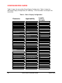
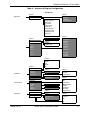
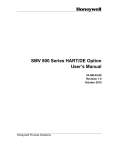
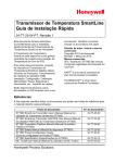
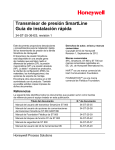
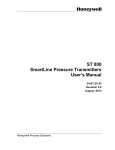
1
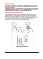
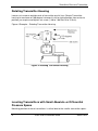
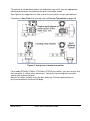
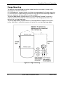
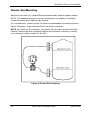
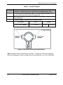
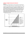
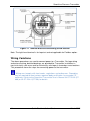
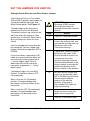
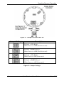
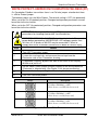
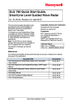
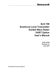
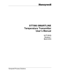
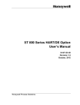
SmartLine Pressure Transmitter Quick Start Installation Guide 34-ST-25-36, Revision 3, April 2015 This document provides descriptions and procedures for the Quick Installation of Honeywell’s family of SmartLine Pressure Transmitters. The SmartLine Pressure Transmitter is available in a variety of models for measuring Differential Pressure (DP), Gauge Pressure (GP), and Absolute Pressure (AP). For full details refer to the manuals listed below for protocols, human interface (HMI), Operation, Installation, Configuration, Calibration, Maintenance, Parts, Safety and Approvals etc. including options.. Copyrights, Notices and Trademarks Copyright 2012 by Honeywell Revision 2, August 2013 Trademarks SFC, SmartLine, ST 800 and ST 700 are U.S. registered trademarks of Honeywell Inc. ® HART and FOUNDATION™ are trademarks of FieldComm Group™ Various other support documents are available on the CD supplied with your shipment. Documents in hardcopy can also be ordered. References The following list identifies all documents that may be sources of reference for material discussed in this publication. Document Title ST 800 SmartLine Transmitter User’s Manual Document # 34-ST-25-35 ST 700 SmartLine Transmitter User’s Manual 34-ST-25-44 ST 800 SmartLine Transmitter HART/DE User Manual ST 700 SmartLine Transmitter HART/DE User Manual 34-ST-25-38 34-ST-25-47 ST 800 Foundation Fieldbus Manual ST 700 Foundation Fieldbus Manual 34-ST-25-39 34-ST-25-48 ST 800 / ST 700 FF Function Blocks Manual 34-ST-25-42 ST 800 Safety Manual 34-ST-25-37 MC Toolkit User Manual (MCT202) MC Toolkit User Manual (MCT404) 34-ST-25-20 34-ST-25-50 Honeywell Process Solutions SmartLine Pressure Transmitter Table of Contents Installation .................................................................................................................... 3 Mounting the Transmitter ............................................................................................. 3 Bracket Mounting .................................................................................................. 4 Optional Mounting Bracket .................................................................................... 4 Existing Mounting Bracket..................................................................................... 5 Rotating Transmitter Housing................................................................................ 6 Leveling Transmitters with Small Absolute or Differential Pressure Spans ........... 6 Flange Mounting ................................................................................................... 8 Flush Mounting...................................................................................................... 9 Remote Seal Mounting........................................................................................ 10 Conduit Entry Plugs and Adapters ............................................................................. 11 Wiring Connections and Power Up............................................................................. 13 Wiring Variations ................................................................................................. 14 Explosion-Proof Conduit Seal .................................................................................... 15 Trim the Transmitter ................................................................................................... 16 Procedure to Trim the Transmitter ...................................................................... 16 Set the Jumpers ......................................................................................................... 17 Setting Failsafe Direction and Write Protect Jumpers ......................................... 17 Write Protect Jumper on Foundation Fieldbus (FF).................................................... 19 Configuration Guide ................................................................................................... 20 Tables Table 1 - Conduit Entry Plugs ............................................................................................11 Table 2 - Conduit Adapters ................................................................................................12 Table 3 – Basic Display Configuration ..............................................................................20 Table 4 – Advanced Display Configuration.......................................................................21 Figures Figure 1: Mounting Brackets ............................................................................................... 3 Figure 2: Angle Mounting Bracket ...................................................................................... 4 Figure 3: LGP and LAP models .......................................................................................... 5 Figure 4: Rotating Transmitter Housing ............................................................................. 6 Figure 5: Using level to mount transmitter ......................................................................... 7 Figure 6: Flange mounting................................................................................................... 8 Figure 7: Flush Mounting ..................................................................................................... 9 Figure 8: Remote Seal mounting .......................................................................................10 Figure 9: Electronic Housing Conduit Entries ...................................................................12 Figure 10: Two-wire power/current loop............................................................................13 Figure 11: Terminal Block and Grounding Screw location ..............................................14 Figure 12: Jumper Location................................................................................................18 Figure 13: Jumper Settings ................................................................................................18 Figure 14: Fieldbus Write Protect ......................................................................................19 2 Quick Start Installation Guide March 2015 INSTALLATION Evaluate the site selected for the Transmitter installation with respect to the process system design specifications and Honeywell’s published performance characteristics for your particular model. Temperature extremes can affect display quality. The display can become unreadable at temperature extremes; however, this is only a temporary condition. The display will again be readable when temperatures return to within operable limits. MOUNTING THE TRANSMITTER Transmitter models, except flush mounts and those with integral flanges, can be attached to a two-inch (50 millimeter) vertical or horizontal pipe using Honeywell’s optional angle or flat mounting bracket; alternately you can use your own bracket. Flush-mount models are attached directly to a process pipe or tank by a one-inch weld nipple. Models with integral flanges are supported by the flange connection. Typical Bracket mounted and Flange Mounted Installations Figure 1: Mounting Brackets March 2015 Quick Start Installation Guide 3 SmartLine Pressure Transmitter Bracket Mounting Optional mounting bracket, see Figure 2 Existing mounting bracket, see Figure 3 Rotate the transmitter housing, see Figure 4 Level a transmitter with small absolute or differential pressure spans, see Figure 5. Optional Mounting Bracket Position bracket on 2-inch (50.8 mm) and install “U” bolt around pipe and through holes in bracket. Secure with nuts and lock washers provided. Figure 2 Example - Angle mounting bracket secured to horizontal or vertical pipe. Figure 2: Angle Mounting Bracket 4 Quick Start Installation Guide March 2015 Existing Mounting Bracket Align appropriate mounting holes in transmitter with holes in bracket and secure with bolts and washers provided. NOTE: If the meter body is hexagonal, you must use the additional bracket supplied. If meter body is round, discard the bracket. Example – LGP model transmitter mounted to optional angle mounting bracket. If Transmitter is…. Then…. DP, Dual Head GP, Dual Head AP and DP Remote Seals. Use alternate mounting holes in end of heads. In-line GP and AP (LGP model) or GP/AP Remote Seal Use smaller “U” bolt provided to attach meter body to bracket. See Figure 3. Figure 3: LGP and LAP models March 2015 Quick Start Installation Guide 5 SmartLine Pressure Transmitter Rotating Transmitter Housing Loosen set screw on outside neck of transmitter one full turn. Rotate Transmitter housing in maximum of 180 degree increment in left or right direction from center to position you require and tighten set screw (1.46 to 1.68 Nm/13 to 15 lb-in). Figure 4 Example – Rotating Transmitter Housing. Figure 4: Rotating Transmitter Housing Leveling Transmitters with Small Absolute or Differential Pressure Spans Mounting position of these transmitters is critical due to the smaller transmitter spans. 6 Quick Start Installation Guide March 2015 To minimize these positional effects on calibration (zero shift), take the appropriate mounting precautions that follow for the given transmitter model. See Figure 5 for suggestions on how to level the transmitter using a spirit balance. To perform a Zero Trim after leveling, refer to Trim the Transmitter on page 16. Figure 5: Using level to mount transmitter For a model STA840, STA822, STA740 or STA722 transmitters, you must ensure that the transmitter is vertical when mounting it. You do this by leveling the transmitter side-to-side and front-to-back. Mount transmitter vertically to assure best accuracy. Position spirit balance on pressure connection surface of AP body. March 2015 Quick Start Installation Guide 7 SmartLine Pressure Transmitter Flange Mounting To mount a flange mounted transmitter model, bolt the transmitter’s flange to the flange pipe on the wall of the tank. On insulated tanks, remove enough insulation to accommodate the flange extension. It is the End User’s responsibility to provide a flange gasket and mounting hardware that are suitable for the transmitter’s service condition. To prevent degradation of performance in Flush-Mounted Flanged Transmitters, exercise care to ensure that the internal diameter of the flange gasket does not obstruct the sensing diaphragm. To prevent degradation of performance in Extended Mount Flanged Transmitters, ensure that there is sufficient clearance in front of the sensing diaphragm body. Figure 6: Flange mounting 8 Quick Start Installation Guide March 2015 Flush Mounting To mount a flush mounted transmitter model, cut a hole for a 1-inch standard pipe in the tank or pipe where the transmitter is to be mounted. See Figure 7 Weld the 1-inch mounting sleeve to the wall of the tank or to the hole cut on the pipe. Insert the meter body of the transmitter into the mounting sleeve and secure with the locking bolt. Tighten the bolt to a torque of 6.4 Nm ±0.30 Nm [4.7 ft.-lbs. ±0.2 ft.-lbs.] Once the transmitter is mounted, the transmitter housing can be rotated to the desired position. See Figure 7. Figure 7: Flush Mounting March 2015 Quick Start Installation Guide 9 SmartLine Pressure Transmitter Remote Seal Mounting Mount the transmitter at a remote distance determined by length of capillary tubing. NOTE: The combination of tank vacuum and high pressure capillary head effect should not exceed 9 psi (300 mm Hg) absolute. On insulated tanks, remove enough insulation to accommodate the mounting sleeve. Figure 8 Example – Typical Remote Seal Transmitter installation. NOTE: For Sanitary 3-A installations, only mount the transmitter outside of the NonProduct Contact area where incidental contact with the process material is unlikely, use a minimum capillary length of 1.5m (5ft.) Figure 8: Remote Seal mounting 10 Quick Start Installation Guide March 2015 CONDUIT ENTRY PLUGS AND ADAPTERS Procedures It is the User/Installer’s responsibility to install the Transmitters in accordance with national and local code requirements. Conduit entry plugs and adapters shall be suitable for the environment, shall be certified for the hazardous location when required and acceptable to the authority having jurisdiction for the plant. CONDUIT ENTRY PRECAUTIONARY NOTICE THE CONDUIT/CABLE GLAND ENTRIES OF THIS PRODUCT ARE SUPPLIED WITH PLASTIC DUST CAPS WHICH ARE NOT TO BE USED IN SERVICE. IT IS THE USER’S RESPONSIBILITY TO REPLACE THE DUST CAPS WITH CABLE GLANDS, ADAPTORS AND/OR BLANKING PLUGS WHICH ARE SUITABLE FOR THE ENVIRONMENT INTO WHICH THIS PRODUCT WILL BE INSTALLED. THIS INCLUDES ENSURING COMPLIANCE WITH HAZARDOUS LOCATION REQUIREMENTS AND REQUIREMENTS OF OTHER GOVERNING AUTHORITIES AS APPLICABLE. Use the following procedures for installation. Table 1 - Conduit Entry Plugs Step 1 Action Remove the protective plastic cap from the threaded conduit entry. 2 To ensure the environmental ingress protection rating on tapered threads (NPT), a non-hardening thread sealant may be used. 3 Thread the appropriate size conduit plug (M20 or ½” NPT) into the conduit entry opening. Do not install conduit entry plugs in conduit entry openings if adapters or reducers will be used. 4 Tighten adapters according to the following table. March 2015 Description Tool M20 Conduit Entry 10mm Hex Wrench 32 Nm 24 Lb-ft ½” NPT Conduit Entry 10mm Hex Wrench 32 Nm 24 Lb-ft Quick Start Installation Guide Torque 11 SmartLine Pressure Transmitter Table 2 - Conduit Adapters Step 1 Action Remove the protective plastic cap from the threaded conduit entry. 2 To ensure the environmental ingress rating on tapered threads (NPT), a non-hardening thread sealant may be used. 3 Thread the appropriate size adapter (M20 or ½ NPT) into the conduit entry opening 4 Tighten adapters according to the following table. Description Tool ½ to ¾ NPT Adapter 1 ¼” Wrench Torque 32 Nm 24 Lb-ft Figure 9: Electronic Housing Conduit Entries Note. No plugs come installed in the housings. All housings come with temporary plastic dust protectors (red) installed and are not certified for use in any installation 12 Quick Start Installation Guide March 2015 WIRING CONNECTIONS AND POWER UP Summary The transmitter is designed to operate in a two-wire power/current loop with loop resistance and power supply voltage within the operating range shown in Figure 10 Loop wiring is connected to the transmitter by simply attaching the positive (+) and negative (–) loop wires to the positive (+) and negative (–) SIGNAL screw terminals on the terminal block in the transmitter’s electronics housing shown in Figure 11. Each transmitter includes an internal terminal to connect it to earth ground. Also a ground terminal can be optionally added to the outside of the electronics housing. While it is not necessary to ground the transmitter for proper operation, doing so tends to minimize the possible effects of noise on the output signal and affords protection against lightning and static discharge. An optional lightning terminal block can be installed in place of the non-lightning terminal block for Transmitters that will be installed in an area that is highly susceptible to lightning strikes. Figure 10: Two-wire power/current loop March 2015 Quick Start Installation Guide 13 SmartLine Pressure Transmitter Figure 11: Terminal Block and Grounding Screw location Note: The right hand terminal is for loop test and not applicable for Fieldbus option. Wiring Variations The above procedures are used to connect power to a Transmitter. For loop wiring and external wiring, detailed drawings are provided for Transmitter installation in non-intrinsically safe areas and for intrinsically safe loops in hazardous area locations. This procedure shows the steps for connecting power to the transmitter. Wiring must comply with local codes, regulations and ordinances. Grounding may be required to meet various approval body certification, for example CE conformity. Refer to the SmartLine Transmitter User’s Manual 34-ST-25-35 (ST 800) or 34-ST-25-44 (ST 700) for details. 14 Quick Start Installation Guide March 2015 EXPLOSION-PROOF CONDUIT SEAL When installed as explosion proof in a Division 1 Hazardous Location, keep covers tight while the Transmitter is energized. Disconnect power to the Transmitter in the non-hazardous area prior to removing end caps for service. When installed as non-incendive equipment in a Division 2 hazardous location, disconnect power to the Transmitter in the non-hazardous area, or determine that the location is non-hazardous before disconnecting or connecting the Transmitter wires. Transmitters installed as explosion proof in Class I, Division 1, Group A Hazardous (classified) locations in accordance with ANSI/NFPA 70, the US National Electrical Code, require a LISTED explosion proof seal to be installed in the conduit, within 18 inches (457.2 mm) of the Transmitter. Crouse-Hinds type EYS/EYD or EYSX/EYDX are examples of LISTED explosion proof seals that meet this requirement. Transmitters installed as explosion proof in Class I, Division 1, Group B, C or D hazardous (classified) locations do not require that explosion proof seal be installed in the conduit. Step Action 1 See Figure 11, above, for parts locations. 2 Remove the end cap cover from the terminal block end of the Electronics Housing 3 Feed loop power leads through one end of the conduit entrances on either side of the Electronics Housing. The Transmitter accepts up to 16 AWG wire. 4 Plug the unused conduit entrance as specified in Table 1. 5 Connect the positive loop power lead to the positive (+) terminal and the negative loop power lead to the negative (-) terminal. Note that the Transmitter is not polarity-sensitive. 6 Replace the end cap, and secure it in place using a 1.5 mm hex wrench. March 2015 Quick Start Installation Guide 15 SmartLine Pressure Transmitter TRIM THE TRANSMITTER Procedure to Trim the Transmitter For a transmitter with a small differential pressure span, you must ensure that the transmitter is vertical when mounting it. You do this by leveling the transmitter sideto-side and front-to-back. See Figure 5 for suggestions on how to level the transmitter using a spirit balance. You must also zero the transmitter by following the steps in this table. Step 16 Action 1 Attach the transmitter to the mounting bracket but do not completely tighten the mounting bolts 2 Connect a tube between the input connections in the high pressure (HP) and low pressure (LP) heads to eliminate the affects of any surrounding air currents. 3 Connect 24 Vdc power to the transmitter. For HART/DE connect a digital voltmeter to monitor the PV output. 4 Use applicable communicator to establish communications with the transmitter. For DE transmitter use SFC, SCT, or MCT. For Hart, use MCT or other Hart Communicator with applicable Honeywell DD's. For Fieldbus, use NI FBUS tools with applicable Honeywell DD's. 5 While reading the transmitter’s output on a communication tool or a voltmeter, position the transmitter so the output reading is at or near zero, and then completely tighten the mounting bolts. 6 The Local Display or applicable communicator can be used to perform the Zero Corrects. This corrects the transmitter for any minor error that may occur after the mounting bolts are tightened. 7 Remove the tube from between the input connections, the power, and the digital voltmeter or communication tool. Quick Start Installation Guide March 2015 SET THE JUMPERS FOR HART/DE Setting Failsafe Direction and Write Protect Jumpers The SmartLine Pressure Transmitter (DE or HART) provides two jumpers to set the desired failsafe action and Write Protect option. See Figure 12 The top jumper on the electronics module sets the Failsafe direction. The default setting is up-scale failsafe. Up Scale drives the loop to a value greater than 21mA while Down Scale drives the loop to a value less than 3.8mA. You can change the failsafe direction by moving the Failsafe Jumper (top jumper) to the desired position (UP or DOWN). ATTENTION: Electrostatic Discharge (ESD) hazards. Observe precautions for handling electrostatic sensitive devices Step 1 2 Loosen the end-cap lock, and unscrew the end cap from the Electronics side of the Transmitter housing. 3 If applicable, carefully depress the tabs on the sides of the Display Module and pull it off. If your transmitter is operating in DE mode, the upscale failsafe action will cause the transmitter to generate a “+ infinity” digital signal, while a downscale failsafe will cause the transmitter to generate a “– infinity” digital signal. The bottom jumper sets the Write Protect. The default setting is OFF (Un-protected). If necessary, move the interface connector from the Communication Module to the display module to provide the preferred orientation of the display module in the window. 4 Set the Failsafe Jumper (top jumper) to the desired action (UP or DOWN). And the Write Protect jumper (Bottom jumper) to the desired behavior (Protected or Unprotected) See Table for jumper positioning. 5 Screw on the end cap and tighten the end-cap lock. 6 Turn ON Transmitter power. When set to the On (Protected) position, Changed configuration parameters cannot be written to the transmitter. When set to the OFF (Un-protected) position, Changed configuration parameters can be written to the transmitter. March 2015 Action Turn OFF Transmitter power. Quick Start Installation Guide 17 SmartLine Pressure Transmitter Figure 12: Jumper Location HART/DE Jumper Settings Description Failsafe = UP (High) Write Protect = OFF (Not Protected) Failsafe = DOWN (Low) Write Protect = OFF (Not Protected) Failsafe = UP (High) Write Protect = ON (Protected) Failsafe = DOWN (Low) Write Protect = ON (Protected) Figure 13: Jumper Settings 18 Quick Start Installation Guide March 2015 SmartLine Pressure Transmitter WRITE PROTECT JUMPER ON FOUNDATION FIELDBUS (FF) On Foundation Fieldbus transmitters there is no Failsafe jumper selection but there is a Write Protect jumper. The bottom jumper sets the Write Protect. The default setting is OFF (Un-protected). When set to the On (Protected) position, Changed configuration parameters cannot be written to the transmitter. When set to the OFF (Un-protected) position, Changed configuration parameters can be written to the transmitter. ATTENTION: Electrostatic Discharge (ESD) hazards. Observe precautions for handling electrostatic sensitive devices. Step WARNING! PERSONAL INJURY: Risk of electrical shock. Disconnect power before proceeding. HAZARDOUS LIVE voltages greater than 30 Vrms, 42.4 Vpeak, or 60 VDC may be accessible. Failure to comply with these instructions could result in death or serious injury. Action 1 Turn OFF Transmitter power. 2 Loosen the end-cap lock, and unscrew the end cap from the Electronics side of the Transmitter housing. 3 If applicable, carefully depress the tabs on the sides of the Display Module and pull it off. 4 5 Set the Write Protect jumper (Bottom jumper) to the desired behavior (Protected or Unprotected). See Figure 14 for jumper positioning. Screw on the end cap and tighten the end-cap lock. 6 Turn ON Transmitter power. Image Description Fieldbus SIM Mode = OFF Write Protect = OFF (Not Protected) Fieldbus SIM Mode = OFF Write Protect = ON (Protected) Fieldbus SIM Mode = ON Write Protect = OFF (Not Protected) Figure 14: Fieldbus Write Protect March 2015 Quick Start Installation Guide 19 CONFIGURATION GUIDE Table 3 shows the transmitter Basic Display Configuration. Table 4.shows the Advanced Display Configuration (ST 800 only). Use these tables to configure the transmitter. Table 3 – Basic Display Configuration 20 Parameter Applicability Locally Writable LCD Contrast Always Yes Rotation Time FF Only Yes PV Display HART/DE Yes PV Decimals HART/DE Yes Pressure Units HART/DE Yes Range/Cal Units FF Only Yes Zero Correct Always Yes LRV Correct HART/DE Yes URV Correct HART/DE Yes Reset Corrects HART/DE Yes DAC Zero Trim HART/DE Yes DAC Span Trim HART/DE Yes Loop Test HART/DE Yes LRV Always HART/DE URV Always HART/DE Damping Always HART/DE NAMUR HART/DE Yes Filter Perf HART only Yes Transfer Func HART/DE DP Only Yes Flow Cutoff HART/DE DP Only Yes Flow Breakpoint HART/DE DP Only Yes Tag ID HART/DE Yes Install Date HART/FF HART Only Firmware Always No Protocol Always No Model Key Always No Exit Menu Always n/a Quick Start Installation Guide March 2015 SmartLine Pressure Transmitter Table 4 – Advanced Display Configuration ST 800 Only Diagnostics Display Setup Calibration Transmtr Setup Information March 2015 <Return> Critical Non-Critical <Return> LCD Contrast Common Setup Screen 1 Screen 2 Screen 3 Screen 4 Screen 5 Screen 6 Screen 7 Screen 8 <Return> Set Time Stamp Zero Correct LRV Correct URV Correct Reset Corrects DAC Trim Loop Test <Return> Parameters Enter LRV Enter URV Set LRV Set URV Install Date <Return> Display Elec Module Meterbody <Return> Active Diags Analog Out mode Zero Correct Span Correct Supply Voltage Primary PV Meterbody Temp Elec Module Temp Meterbody Comm Factory Cal DAC Temp Comp <Return> Set contrast <Return> Language Rotation Time <Return> Active Diags Meterbody Elec Module Meterbody Comm <Return> Screen Format Trend Duration PV Selection PV Scaling Display Units Custom Units Decimals Disp Low Lim Disp High Lim Scaling Low Scaling High Custom Tag <Return> Hour Minute Year Month Day <Return> Do ( ) Correct <Return> Set DAC Output Set DAC Normal <Return> Enter (LRV/URV) <Return> Set (LRV/URV) <Return> Firmware Version <Return> Firmware Version HART/DE Version Protocol Quick Start Installation Guide <Return> Trim Zero Trim Span Set DAC Normal <Return> Tag ID Units Damping (sec) NAMUR Selection Filter Perf. Transfer Func. Flow Cutoff Breakpt (%Flow) <Return> Firmware Version Model Key Units LRL URL 21 Sales and Service For application assistance, current specifications, pricing, or name of the nearest Authorized Distributor, contact one of the offices below. ASIA PACIFIC (TAC) [email protected] Australia Honeywell Limited, Phone: +(61) 7-3846 1255, FAX: +(61) 7-3840 6481 Toll Free 1300-36-39-36, Toll Free Fax: 1300-36-04-70 China – PRC – Shanghai, Honeywell China Inc. Phone: (86-21) 5257-4568, Fax: (86-21) 6237-2826 Singapore, Honeywell Pte Ltd. Phone: +(65) 6580 3278. Fax: +(65) 6445-3033 South Korea, Honeywell Korea Co Ltd. Phone:+(822)799 6114. Fax:+(822) 792 9015 EMEA, Phone: + 80012026455 or +44 (0)1202645583. FAX: +44 (0) 1344 655554 Email: (Sales) [email protected] or (TAC) [email protected] AMERICAS, Honeywell Process Solutions, Phone: (TAC) 1-800-423-9883 or 215/641-3610. (Sales) 1-800-343-0228. Email: (Sales) [email protected] or (TAC) [email protected] WARRANTY/REMEDY Honeywell warrants goods of its manufacture as being free of defective materials and faulty workmanship. Contact your local sales office for warranty information. If warranted goods are returned to Honeywell during the period of coverage, Honeywell will repair or replace without charge those items it finds defective. The foregoing is Buyer's sole remedy and is in lieu of all other warranties, expressed or implied, including those of merchantability and fitness for a particular purpose. Specifications may change without notice. The information we supply is believed to be accurate and reliable as of this printing. However, we assume no responsibility for its use. While we provide application assistance personally, through our literature and the Honeywell web site, it is up to the customer to determine the suitability of the product in the application. Honeywell Process Solutions 1250 W Sam Houston Pkwy S Houston, TX 77042 www.honeywellprocess.com 34-ST-25-36 Rev.3 April 2015 2015 Honeywell International Inc.