1
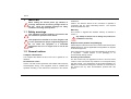
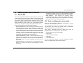
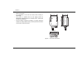
Thank you for buying this AIS receiver.
This product has been engineered to offer you the highest level of
performance and durability and we hope that it will provide many years of
reliable service. We constantly strive to achieve the highest possible
quality standards, should you encounter any problems with this product,
please contact your dealer who will be pleased to offer whatever
assistance you require.
Table of contents
Table of figures
1
Notices ..................................................................................................1
Figure 1
1.1 Safety warnings ......................................................................................1
Figure 2
Items included in the product..................................................... 3
AIS receiver overview................................................................ 4
1.2 General notices ......................................................................................1
Figure 3
Electrical connections to the AIS receiver ................................. 4
2
Typical installation configuration................................................ 5
About your AIS receiver ......................................................................2
Figure 4
2.1 About AIS ...............................................................................................2
Figure 5
AIS receiver dimensions............................................................ 7
2.2 Static and dynamic vessel data..............................................................2
Figure 6
AIS receiver mounting ............................................................... 8
2.3 What's in the box? ..................................................................................3
Figure 7
Position of the VHF antenna connector..................................... 8
3
Installation ............................................................................................5
Figure 8
Connecting to the NMEA0183 data port.................................... 9
3.1 Preparing for installation.........................................................................5
Figure 9
Connecting the power supply .................................................. 10
3.2 Installation procedures ...........................................................................6
Figure 10
Indicator location on the AIS receiver unit ............................... 11
4
Operation ............................................................................................11
4.1 Using the AIS receiver..........................................................................11
4.2 Indicator functions ................................................................................11
5
Troubleshooting .................................................................................12
6
Specifications .....................................................................................13
7
Warranty..............................................................................................14
Notices
1
Notices
!
When reading this manual please pay attention to
warnings marked with the warning triangle shown on
the left. These are important messages for safety,
installation and usage of the product.
Failure to do so can result in personal injury and / or AIS receiver
malfunction.
Caution: The antenna should not be co-located or operated in
conjunction with any other transmitting antenna. The required
antenna impedance is 50Ω.
Warranty
1.1 Safety warnings
!
!
!
This equipment must be installed in accordance with
the instructions provided in this manual.
This equipment is intended as an aid to navigation and
is not a replacement for proper navigational judgement.
Do not install this equipment in a flammable
atmosphere such as in an engine room or near to fuel
tanks.
1.2 General notices
Compass safe distance
The compass safe distance of this unit is 0.5m or greater for 0.3°
deviation.
RF emissions notice
Caution: The AIS receiver generates and radiates radio frequency
electromagnetic energy. This equipment must be installed and
operated according to the instructions contained in this manual.
Page 1
This product is supplied with standard warranty as defined in
section 7.
!
Any attempt to tamper with or damage this product will
invalidate the warranty.
Disposal of this product and packaging
Please dispose of the AIS receiver in accordance with the European
WEEE Directive or with the applicable local regulations for disposal
of electrical equipment.
Every effort has been made to ensure the packaging for this product
is recyclable.
Please dispose of the packaging in an
environmentally friendly manner.
Accuracy of this manual
The AIS receiver may be upgraded from time to time and future
versions of the AIS receiver may therefore not correspond exactly
with this manual. The manufacturer of this product disclaims any
liability for consequences arising from omissions or inaccuracies in
this manual and any other documentation provided with this
product.
About your AIS receiver
2
About your AIS receiver
2.1 About AIS
The marine Automatic Identification System (AIS) is a location and
vessel information reporting system. It allows vessels equipped with
AIS to automatically and dynamically share and regularly update
their position, speed, course and other information such as vessel
identity with similarly equipped vessels. Position is derived from the
Global Positioning System (GPS) and communication between
vessels is by Very High Frequency (VHF) digital transmissions.
There are a number of types of AIS device as follows:
• Class A transceivers. These are similar to class B transceivers,
but are designed to be fitted to large vessels such as cargo ships
and large passenger vessels. Class A transceivers transmit at a
higher VHF signal power than class B transceivers and therefore
can be received by more distant vessels, and also transmit more
frequently. Class A transceivers are mandatory on all vessels
over 300 gross tonnes on international voyages and certain types
of passenger vessels under the SOLAS mandate.
• Class B transceivers. Similar to class A transceivers in many
ways, but are normally lower cost due to the less stringent
performance requirements. Class B transceivers transmit at a
lower power and at a lower reporting rate than class A
transceivers.
• Aids to Navigation (AtoN) transceivers.
AtoNs are
transceivers mounted on buoys or other hazards to shipping
which transmit details of their location to the surrounding vessels.
• AIS receivers.
AIS receivers will generally receive
transmissions from class A transceivers, class B transceivers,
AtoNs and AIS base stations but do not transmit any information
about the vessel on which they are installed.
2.2 Static and dynamic vessel data
There are two categories of information transmitted by an AIS
transceiver: static and dynamic data.
The vessel's dynamic data, which includes location, speed over
ground (SOG) and course over ground (COG), is calculated
automatically using the internal GPS receiver.
Static data is information about the vessel which must be
programmed into an AIS transceiver. This includes:
• Maritime Mobile Service Identity (MMSI)
• Vessel name
• Vessel call sign (if available)
• Vessel type
• Vessel dimensions
In most countries the operation of an AIS transceiver is included
under the vessel's marine VHF licence provisions.
• AIS base stations. AIS base stations are used by Vessel Traffic
Systems to monitor and control the transmissions of AIS
transceivers.
Page 2
About your AIS receiver
2.3 What's in the box?
• Support tools CD
Figure 1 shows the items included with your AIS receiver purchase.
The following sections give a brief overview of each item. Please
ensure all items are present and if any of the items are not present
contact your dealer.
The CD supplied with the package contains the USB drivers to
enable use of the AIS receiver via its USB interface. Also included
on the CD is the product manual.
• Quick start guide
The quick start guide gives a handy one page reference for the
installation process.
AIS receiver
• Product manual
Product CD
Quick
start guide
Screws
(packet of 2)
Product manual
This document is the product manual and should be read thoroughly
prior to any attempt to install or use the AIS receiver.
• Fixing screws
Two fixing screws are provided with the product for mounting of the
AIS receiver. Please refer to section 3.2 for details of how to mount
the AIS receiver.
• AIS receiver unit
Figure 2 shows an overview of the AIS receiver unit.
The AIS receiver has an indicator which provides information to the
user about the status of the AIS receiver. Please refer to section
4.2 for more details of the indicator functions.
Figure 1
Page 3
Items included in the product
About your AIS receiver
Figure 2 shows the AIS receiver mounting holes. Please refer to
section 3.2 for details of how to mount the AIS receiver.
Electrical connections
The AIS receiver has the following connections provided by the
attached cables:
• Power supply
Status indicator
• NMEA0183 data port for connection to chart plotters
• USB for connection to a PC
• VHF antenna connector.
Mounting
hole
Mounting
hole
Chart plotter /
AIS receiver
USB
NMEA0183 device
Power in
VHF antenna connector
Power and data cables
Figure 2
AIS receiver overview
Figure 3
Electrical connections to the AIS receiver
Page 4
Installation
3
Installation
In addition to the items provided with your AIS receiver the following
items will be required for installation:
3.1 Preparing for installation
VHF antenna
Figure 4 shows a typical installation configuration for the AIS
receiver. Please take the time to familiarise yourself with the
system elements and their connections prior to attempting
installation.
VHF Antenna
Chart plotter
Laptop
Connection to a suitable VHF antenna will be required for the AIS
receiver to operate. A standard marine band VHF antenna such as
that used with VHF voice radios will be sufficient. Please take note
of the warnings in section 1 regarding the use of antennas.
Alternatively, if you wish to use an existing VHF antenna, antenna
splitter products are available which allow the existing antenna to be
used with two radio devices, such as a VHF voice radio and the AIS
receiver.
Antenna cables
AIS receiver
Please check that the VHF antenna you intend to use has sufficient
cable to reach between the VHF antenna and the AIS receiver unit.
If it is not sufficient you will need an extension cable. Please contact
your dealer for details of suitable products. For reference the VHF
antenna connector type on the AIS receiver unit is SO239, and is
intended to mate with a PL259 connector.
Power and data cables
NMEA0183 device
Figure 4
Page 5
Typical installation configuration
Power in
The AIS receiver unit is supplied with a one metre long power and
data cable as an integral part of the AIS receiver unit. If you require
longer cables to reach your power supply, please ensure the cables
are capable of carrying an average current of up to 200mA. Means
of connecting the cables together will also be required. The use of
ScotchlokTM connectors is recommended for this purpose.
Installation
Chart plotter
To display received AIS position reports as other vessels on your
chart plotter, you will need to connect your AIS receiver to your chart
plotter. Please refer to the user manual supplied with your chart
plotter for details of how to connect and configure your chart plotter
for use with AIS devices. For general guidance your chart plotter
should be configured to accept NMEA data at 38400 baud
(sometimes referred to as 'NMEA HS' in the plotter configuration
menu). You may also need to enable the display of AIS targets in
the chart options.
Connection to a PC
If you choose to use a PC with suitable charting software to display
received AIS messages as other vessels, this can be accomplished
by connecting the USB connector directly to the PC. Your PC may
require USB software drivers to connect to the AIS receiver and
these can be found on the CD included with the product.
3.2 Installation procedures
Before beginning installation of your AIS receiver, please ensure
you have the necessary additional items as detailed in section 3.1.
It is strongly recommended that you read all of the instructions in
this manual prior to installation.
If after reading this manual you are unsure about any element of the
installation process please contact your dealer for advice.
The following sections explain the installation process step by step
for each of the main elements of the system.
Step 1 - Installing the AIS receiver
Please note the following guidelines when selecting a location for
your AIS receiver:
• The AIS receiver must be fitted in a location where it is at least
0.5m from a compass.
• There should be adequate space around the AIS receiver for
routing of cables. See Figure 5 for details of the AIS receiver
dimensions.
• The ambient temperature around the AIS receiver should be
maintained between -10°C and +55°C.
• The AIS receiver should not be located in a flammable or
hazardous atmosphere such as in an engine room or near to fuel
tanks.
• The AIS receiver is not designed to be waterproof and it is
therefore not recommended that the AIS receiver be subjected to
spray or submersion.
Page 6
Installation
• It is recommended that the AIS receiver is installed in a 'below
decks' environment.
50 mm
80 mm
• The product is supplied with two self tapping screws for
attachment of the AIS receiver to a suitable surface. Please refer
to Figure 6 for guidance.
• The AIS receiver should be mounted in a location where the
indicator is readily visible as this provides important information
on the status of the AIS receiver.
65.5 mm
Figure 5
Page 7
33.25 mm
AIS receiver dimensions
70 mm
• It is acceptable to mount the AIS receiver either vertically or
horizontally.
Installation
Step 2 - Connecting the VHF antenna
Route the cable from the VHF antenna to the AIS receiver and
connect to the VHF connector on the AIS receiver as shown in
Figure 7.
A standard marine band VHF antenna or AIS antenna should be
used with the AIS receiver. The connector type on the AIS receiver
is SO239. Your chosen VHF antenna requires a PL259 connector
to mate with this. If your VHF antenna does not use this type of
connector please contact your dealer for details of available
adaptors.
Figure 6
VHF antenna connector
AIS receiver mounting
Figure 7
Position of the VHF antenna connector
Page 8
Installation
Step 3 - Connecting to a chart plotter
The NMEA0183 data port provides the connection to your chart
plotter and consists of four wires colour coded as shown in the table
below and in Figure 8. Connect the two ‘Transmit’ wires to the
appropriate connections on your chart plotter. Please refer to your
chart plotter manual for more information.
To multiplex your NMEA0183 device data via the AIS receiver
simply connect the device’s NMEA0183 output to the receive + and
receive - terminals as defined in the table above. The NMEA0183
input baud rate is 4800 baud. Please ensure your NMEA0183
device operates at 4800 baud.
The NMEA0183 data port output operates at a baud rate of 38400
baud. Please ensure your chart plotter is configured to receive data
from the AIS receiver via its NMEA0183 port at 38400 baud.
Please note that the 'Receive' connections should not be connected
to your chart plotter as it is not normal for the receiver to receive
data from the chart plotter.
Yellow
Brown
NMEA0183 function
Wire colour
Blue
Transmit + (Output)
Yellow
Orange
Transmit - (Output)
Brown
Receive + (Input)
Blue
Receive - (Input)
Orange
Connecting an optional NMEA0183 device
If you wish to connect a NMEA0183 device (such as a heading
sensor) to your chart plotter, but your chart plotter only has a single
NMEA0183 input, it is possible to use the AIS receiver’s NMEA0183
multiplexing feature to connect both devices to the chart plotter.
Page 9
Figure 8
Connecting to the NMEA0183 data port
Transmit +
Transmit –
Receive +
Receive –
Installation
Connection to a PC
Step 4 - Connecting to a power supply
The AIS receiver is supplied with a USB connector for connection to
a PC. If your PC requires USB drivers to operate with the AIS
receiver these can be found on the CD provided with the product.
The AIS receiver requires a 12V or 24V power supply typically
provided by the vessel's battery.
When inserting the USB connector into a PC for the first time, you
are likely to be prompted to select the drivers for the USB device.
Insert the CD provided with the product into the PC and select
‘Search for drivers on this computer’. Your PC should find the
drivers located on the CD and install them on the PC.
Please note: If you connect the USB connector to an alternative
port on your PC this procedure may be repeated.
It is recommended that crimped and soldered lugs are used to
connect the AIS receiver to the power source.
It is recommended that the power supply is connected via a suitable
circuit breaker and/or 1A fuse block.
1. Connect the red wire to the power supply positive terminal.
2. Connect the black wire to the supply negative terminal.
The AIS receiver will appear as an additional COM port on your PC.
This COM port should be selected as the AIS data source in
charting applications. The port operates at 38400 baud.
Figure 9
Red
Power supply +
Black
Power supply –
Connecting the power supply
Page 10
Operation
4
Operation
4.1 Using the AIS receiver
Status indicator
Once the unit has been installed it is ready for use. Providing other
vessels with AIS transceivers installed are within radio range of your
vessel you should see their details appear on your chart plotter or
PC.
Specific details of how to configure your chart plotter to make use of
the AIS receiver features will be given in your chart plotter manual.
If you are using charting software running on a PC, please refer to
the instructions provided with your chart plotting software for details
of how to configure it to display AIS information.
4.2 Indicator functions
The AIS receiver includes a green indicator light as shown in Figure
10. The state of the indicator provides information regarding the
status of the AIS receiver. The status indicator will illuminate when
power is applied to the unit and it is running in normal mode. The
brightness of the indicator will decrease on receipt of AIS
messages.
Page 11
Figure 10 Indicator location on the AIS receiver unit
Troubleshooting
5
Troubleshooting
Issue
Possible cause and remedy
No data is being received
by the chart plotter
•
•
•
Check that the power supply is connected
correctly.
Check that the connections to the chart plotter are
correct.
Check that the VHF antenna is correctly
connected in accordance with the instructions in
the manual
The indicator is not
illuminated
•
Check that the power supply is connected
correctly.
The indicator is flashing
but AIS targets are not
displayed on the chart
plotter
•
Check the chart plotter NMEA port configuration is
set to receive AIS data
Check the chart plotter display settings are
configured to show AIS targets
Consult the chart plotter manufacturers
documentation
•
•
The indicator is
illuminated but not
flashing to indicate
receipt of AIS data
•
•
Check there are vessels equipped with AIS
transceivers in your area
Check the VHF antenna is correctly installed and
connected
If the guidance given in the table above does not rectify the problem
you are experiencing, please contact your dealer for further
assistance.
Page 12
Specifications
6
Specifications
Receiver Sensitivity
Better than -112dBm at 20% Packet
Error Rate
Parameter
Value
Environmental
Operating temperature: -25ºC to +55ºC
Dimensions
80 x 65.5 x 33.25 mm (L x W x H)
IPx2
Weight
200g (AIS receiver unit only)
Ingress Protection
rating
Power
DC (9.6V - 28.8V)
Average power consumption <1.5W
Peak current rating 200mA
Electrical Interfaces
USB 2.0 38400 baud bi-directional
NMEA0183 38400 baud (output) 4800
baud (input)
Connectors
VHF antenna connector type: SO239
50Ω
USB 2.0
NMEA0183
Power
Dual channel receiver
Fixed frequency reception at
161.975MHz and 162.025MHz
Channel Bandwidth
25kHz
Page 13
Warranty
7
Warranty
1 Year Limited Warranty
This product is warranted against factory defects in material and
workmanship for a period of 1 (One) Year from date of purchase or
receipt as a gift. During the warranty period ACR Electronics, Inc.
will repair or, at its option, replace the unit at no cost to you for labor,
materials and return transportation from ACR. For further
assistance, please contact our Technical Service Department at
ACR Electronics, Inc., 5757 Ravenswood Road, Fort Lauderdale,
FL 3312-6645. Email: [email protected], Fax: +1 (954)
983-5087, Telephone: +1 (954) 981-3333.
This warranty does not apply if the product has been damaged by
accident or misuse, or as a result of service or modification
performed by an unauthorized factory. Except as otherwise
expressly stated inthe previous paragraph, THE COMPANY
MAKES NO REPRESENTATION OR WARRANTY OF ANY KIND,
EXPRESS OR IMPLIED, AS TO MERCHANTABILITY, FITNESS
FOR A PARTICULAR PURPOSE, OR ANY OTHER MATTER WITH
RESPECT TO THIS PRODUCT. The company shall not be liable for
consequential or special damages.
To place the warranty
www.acrelectronics.com.
in
effect,
register
online
at
©2010 by ACR Electronics, Inc., part of Cobham plc. All rights
reserved. Reproduction in whole or in part is permitted only with
permission of ACR Electronics, Inc.
Trademarks or registered trademarks are the property of their
respective owners.
Page 14
201-0074 V2
Thank you for reading this data sheet.
For pricing or for further information, please contact us at our UK Office, using the details
below.
UK Office
Keison Products,
P.O. Box 2124, Chelmsford, Essex, CM1 3UP, England.
Tel: +44 (0)1245 600560
Fax: +44 (0)1245 808399
Email: [email protected]
Please note - Product designs and specifications are subject to change without notice. The user is responsible for determining the
suitability of this product.