1
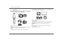
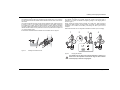
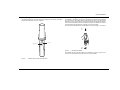
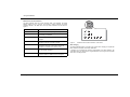
Contents
Figures
1 Notices ..................................................................................2
1.1 Safety warnings.................................................................2
1.2 General notices .................................................................2
2 About AIS ..............................................................................3
2.1 Static and dynamic vessel data.........................................3
3 Installing and charging the Identifier .................................4
3.1 Supplied items...................................................................4
3.2 Installing the Identifier bracket...........................................5
3.3 Charging the Identifier .......................................................5
4 Configuring the Identifier ....................................................6
4.1 Installing proAIS2 - PC ......................................................6
4.2 Installing proAIS2 - Mac ....................................................6
4.3 Connecting to the Identifier ...............................................6
4.4 Basic configuration ............................................................6
4.5 Message configuration ......................................................7
4.6 proAIS2 diagnostics ..........................................................8
5 Using the Identifier...............................................................9
5.1 Activating and deactivating the Identifier...........................9
5.2 Status indicator................................................................10
5.3 SOS button......................................................................11
6 Troubleshooting .................................................................12
7 Specification .......................................................................13
Figure 1 Identifier package contents .........................................4
Figure 2 Configuration pack contents........................................4
Figure 3 Installing the Identifier bracket.....................................5
Figure 4 Charging the Identifier .................................................5
Figure 5 proAIS2 configuration tab............................................7
Figure 6 proAIS2 message configuration tab ............................8
Figure 7 Identifier status indicator and SOS button...................9
Figure 8 Activating the Identifier ................................................9
Figure 9 Identified common status indications - whilst active..10
Figure 10 SOS function activation ...........................................11
Page 1
Notices
1
Notices
!
1.1
When reading this manual please pay attention to warnings marked with
the warning triangle shown on the left. These are important messages for
safety, installation and usage of the product.
Safety warnings
!
This equipment must be installed in accordance with the instructions
provided in this manual.
!
Do not install this equipment in a flammable atmosphere such as in an
engine room or near to fuel tanks.
!
Any attempt to tamper with or damage this product will invalidate the
warranty.
!
1.2
This product contains a Lithium-Ion battery. Never expose to fire or high
temperatures. Do not attempt to dissasemble the product. Do not short
circuit the battery or attempt to charge with equipment other than the
supplied charger.
General notices
Position source
All marine Automatic Identification System (AIS) transceivers utilise a satellite based
location system such as the Global Positioning System (GPS) network.
The accuracy of a GPS position fix is variable and is affected by factors such as the
antenna positioning, how many satellites are used to determine a position and for how
long satellite information has been received for.
RF emissions notice
Caution: The AIS transceiver generates and radiates radio frequency electromagnetic
energy. This equipment must be installed and operated according to the instructions
contained in this manual. Failure to do so can result in personal injury and / or AIS
transceiver malfunction.
Accuracy of this manual
The AIS transceiver may be upgraded from time to time and future versions of the AIS
transceiver may therefore not correspond exactly with this manual. Information
Page 2
contained in this manual is liable to change without notice. The manufacturer of this
product disclaims any liability for consequences arising from omissions or inaccuracies
in this manual and any other documentation provided with this product.
About AIS
2
About AIS
The marine Automatic Identification System (AIS) is a location and vessel information
reporting system. It allows vessels equipped with AIS to automatically and dynamically
share and regularly update their position, speed, course and other information such as
vessel identity with similarly equipped vessels. Position is derived from the Global
Positioning System (GPS) and communication between vessels is by Very High
Frequency (VHF) digital transmissions.
There are a number of types of AIS device as follows:
•
Class A transceivers. These are similar to class B transceivers, but are designed
to be fitted to large vessels such as cargo ships and large passenger vessels. Class
A transceivers transmit at a higher VHF signal power than class B transceivers and
therefore can be received by more distant vessels. They also transmit more
frequently. Class A transceivers are mandatory on all vessels over 300 gross tonnes
on international voyages and certain types of passenger vessels under SOLAS
regulations.
•
Class B transceivers. Similar to class A transceivers in many ways, but are
normally lower cost due to the less stringent performance requirements. Class B
transceivers transmit at a lower power and at a lower reporting rate than class A
transceivers.
•
AIS base stations. AIS base stations are used by Vessel Traffic Systems to monitor
and control the transmissions of AIS transceivers.
•
Aids to Navigation (AtoN) transceivers. AtoNs are transceivers mounted on
buoys or other hazards to shipping which transmit details of their location to the
surrounding vessels.
•
AIS receivers. AIS receivers will generally receive transmissions from class A
transceivers, class B transceivers, AtoNs and AIS base stations but do not transmit
any information about the vessel on which they are installed.
•
AIS Identifier. The Identifier is a unique, self-contained AIS vessel tracking device.
The key features of the AIS Identifier are as follows:
• Self-contained VHF and GPS antennas
• Internal rechargeable battery pack for up to 5 days of operation
• Electronic security link to vessel mounting bracket
• Simple installation
2.1
Static and dynamic vessel data
There are two categories of information transmitted by an AIS transceiver: static and
dynamic data.
The vessel's dynamic data, which includes location, speed over ground (SOG) and
course over ground (COG), is calculated automatically using the internal GPS receiver.
Static data is information about the vessel which must be programmed into the AIS
transceiver. This includes:
•
Maritime Mobile Service Identity (MMSI)
•
Vessel name
•
Vessel call sign (if available)
•
Vessel type
• Vessel dimensions
In most countries the operation of an AIS transceiver is included under the vessel's
marine VHF licence provisions. The vessel on to which the AIS unit is to be installed
must therefore possess a current VHF radiotelephone licence which lists the AIS
system, vessel Call Sign and MMSI number.
!
An MMSI number is required in order for the AIS transceiver to operate.
Please contact the relevant authority in your country for more
information.
Page 3
Installing and charging the Identifier
3
Installing and charging the Identifier
Vessel bracket and fixings
3.1
Supplied items
The vessel bracket is used to attach the Identifier to the vessel. It also automatically
switches the Identifier on when installed in the bracket.
Figure 1 shows the items that are included with each Identifier. Note that a configuration
dock and PC configuration software are supplied separately in a configuration pack.
The contents of the configuration pack are shown in Figure 2.
Product CD
Product manual
Charger
Configuration dock
USB Cable
Vessel bracket and fixings
Figure 2
Configuration pack contents
Configuration dock
The configuration dock is used to connect the Identifier to a PC or Mac during
configuration. The configuration dock can also be used to charge the Identifier.
USB Cable
Identifier
The USB Cable is used to connect the configuration dock to the PC or Mac.
CD
Figure 1
Identifier package contents
The CD contains the configuration software and this user manual in PDF format.
Identifier
Product manual
The Identifier AIS tracking device. The Identifier is self-contained and incorporates a
rechargeable battery pack, VHF antenna and GPS antenna.
This document is the product manual.
Charger
The charger base is used to recharge the Identifier from an AC mains supply.
Page 4
Installing and charging the Identifier
3.2
Installing the Identifier bracket
3.3
Charging the Identifier
The Identifier must be located in the supplied mounting bracket when in use. Insertion
into the bracket activates the Identifier and the Identifier is inactive when removed from
the bracket.
The Identifier is shipped with a partial charge and requires a full charge prior to
installation on a vessel. The Identifier is charged by placing it in the charging dock as
shown in Figure 4.
The bracket should be fixed to the vessel using the supplied u-bolts, washers and nuts
as shown in Figure 3. The bracket should be mounted to a non-metallic vertical pole
and installed in a location where the status indicator is visible. Ideally the Identifier
should be installed approximately 2m above sea level. The area around and above the
Identifier should be clear from any obstructions as these may affect GPS reception and
/ or VHF transmission range.
During charging the status indicator will flash at a steady rate. When charging is
complete the status indicator will stop flashing and remain constantly illuminated.
Depending on the condition of the battery a full charge can take up to 5 hours to
complete.
Note that the Identifier can be configured as described in section 4 prior to charging.
Ensure that the Identifier bracket is installed in the orientation shown in Figure 3.
1
2
11
12
3
1
2
10
3
9
4
8
7
Figure 3
4
6
5
Installing the Identifier bracket
Figure 4
!
Charging the Identifier
The Identifier will not charge if the internal temperature is below 0°C or
above 40°C. If the temperature is outside this range the status indicator
will flash rapidly to indicate a charging fault.
Page 5
Configuring the Identifier
4
Configuring the Identifier
The Identifier transmits standard AIS position and vessel data reports. It requires
configuration with the relevant vessel information prior to installation.
The Identifier can also be configured for position reporting intervals, VHF operating
frequency and other operating parameters listed below.
Configuration is carried out from a PC or MAC running the proAIS2 application supplied
on CD in the configuration pack.
4.1
1.
Installing proAIS2 - PC
Insert the CD into your PC or Mac and navigate to the ‘proAIS2’ then the ‘Windows’
folder. Double click the setup.exe file then follow the on-screen prompts.
If a security warning appears, click 'Install' to continue with the installation.
2.
4.
Once installation is complete, proAIS2 will launch automatically and a start menu
folder and shortcut will be created for future use.
5.
A detailed user guide for proAIS2 is available via the application help menu.
4.2
Installing proAIS2 - Mac
1.
Insert the CD into your Mac, then navigate to the 'proAIS' then the 'OSX' folder.
2.
Double click the proAIS2.dmg file then follow the on screen instructions to
complete the installation.
4.3
Connecting to the Identifier
Connect to the Identifier by inserting it into the configuration dock (supplied in the
configuration pack) and connecting the configuration dock USB cable to a PC or Mac.
The first time the connection is made the USB drivers must be installed. If automatic
installation is not successful the drivers are also provided in a separate folder on the CD
supplied in the configuration pack to allow manual installation.
Once the drivers are installed, launch the proAIS2 application and select the relevant
communications port from the drop down menu. The port will be listed as “USB Serial
Port (COMn)” where n is the number of the port. Click the ‘Connect’ button to connect to
the Identifier. The ‘Disconnect’ button should be clicked once configuration has been
completed and prior to physically disconnecting the Identifier from the PC or Mac.
Page 6
4.4
Basic configuration
All basic configuration is presented on the proAIS2 configuration tab as shown in Figure
5. This tab permits configuration of the following information:
• Ship’s name
Enter the vessel name or other identification.
• Call sign
Enter the vessel call sign (if available).
• MMSI number
Enter the vessel’s 9 digit MMSI number.
• Vessel type
Select the most appropriate vessel type from the drop down list.
• Ship’s dimensions
Enter the vessel dimensions, referenced to the location of the identifier, to the
nearest whole metre.
• Reset paired bracket / holder ID
Checking this option will reset the pairing of the Identifier to a vessel bracket. The
next time the Identifier is placed in a vessel bracket it will be paired with that
bracket. See section 5.1 for further information on bracket pairing.
• Deep sleep mode
Select this option to enable deep sleep mode when the ‘Disconnect’ button is
pressed in proAIS2. Deep sleep mode will put the Identifier in a very low power
consumption mode suitable for storage or shipping. Deep sleep mode will exit the
next time the Identifier is inserted into a charger or configuration dock.
• Configuration of AIS operating frequencies
Select the required operating VHF frequencies for transmissions. The default
channels are Channel A = 161.975MHz and Channel B = 162.025MHz. It is critical
that these frequencies match the configuration of any receiving equipment.
To save the configuration to the Identifier click the ‘Write Configuration’ button and
acknowledge the MMSI programming warning.
Configuring the Identifier
•
•
•
•
•
Figure 5
4.5
proAIS2 configuration tab
Message configuration
All AIS messaging configuration is presented on the proAIS2 Message Configuration
tab as shown in Figure 6. This tab permits configuration of the following information:
• Message 18 interval below SOG threshold
Sets the time in seconds between transmissions of message 18 when the vessel is
travelling at a speed below the threshold value. Message 18 contains vessel MMSI,
position, course and speed information.
• Speed over Ground (SOG) threshold
Sets the speed over ground (in knots) at which the Identifier will switch transmission
intervals for message 18. There are two transmission intervals; one for speeds
below the threshold and one for speeds above the threshold. This parameter sets
that speed threshold.
•
•
•
Message 18 interval above SOG threshold
Sets the time in seconds between transmissions of message 18 when the vessel is
travelling at a speed over ground above the threshold speed value. Message 18
contains vessel MMSI, position, course and speed information.
Message 24 and 25 interval
Sets the time in seconds between transmissions of messages 24 and 25. Message
24 contains vessel name, call sign, dimensions and vessel type. Message 25 can
be configured for transmission if the Identifier is located in a bracket/holder other
than its paired bracket/holder. This allows a shore system to locate and identify
vessels carrying the wrong Identifier.
SOS message configuration (Message 14)
Sets the text transmitted in the Identifier SOS message. Text up to 13 characters in
length can be transmitted. By default the text transmitted is set to ‘MAYDAY
MAYDAY’.
Message 25 type
The Identifier can be configured to transmit message 25 (a binary data message)
when operating in a vessel bracket/holder other that its correctly paired bracket/
holder. The message type can be configured as disabled (no message is sent),
broadcast message transmission (sent to all receivers) or addressed message
transmission (sent only to a specific shore station).
Destination MMSI
When message 25 is configured for addressed transmission, the MMSI of the
destination should be entered here.
Message text
The text content for message 25 should be entered here.
Designated area code (DAC)
The designated area code for message 25 should be entered here. This value will
depend on AIS network configuration.
Function Identifier (FI)
The Function Identifier for message 25 should be entered here. This value will
depend on AIS network configuration.
To save the configuration to the Identifier click the ‘Write Configuration’ button and
acknowledge the MMSI programming warning.
Page 7
Configuring the Identifier
The Identifier will operate for approximately 5 days with the following message
configuration:
• Message 18 intervals both set to 5 minutes (300 seconds)
• Speed over Ground threshold not used (as both message 18 intervals are the
same)
•
Message 24 and 25 interval set to 10 minutes (600 seconds)
!
4.6
The operating time from a complete charge is dependent on the
configured reporting intervals. Shorter reporting intervals will reduce
the operating time. The examples provided here are intended as a guide
as actual operating time also depends on external factors such as
temperature and GPS signal quality.
proAIS2 diagnostics
The Diagnostics tab provides operating diagnostics, product version information and
status. This information may be required when requesting product support.
Figure 6
Page 8
proAIS2 message configuration tab
Using the Identifier
5
Using the Identifier
5.1
The Identifier is ready for use once charged and configured. The location of the status
indicator and SOS button are shown in Figure 7.
Activating and deactivating the Identifier
The Identifier is activated by placing it in the supplied vessel bracket and de-activated
when removed from the bracket. Note that the Identifier is ‘paired’ to the first bracket
with which it is used. If the Identifier is configured to transmit message 25 this message
will be sent if the Identifier is placed in the incorrect bracket. The Identifier will continue
to report position and vessel data as configured in the incorrect bracket.
Insert and lock the Identifier into the vessel bracket, as shown in Figure 8, to activate it.
1
SOS button
Status indicator
2
Figure 8
Activating the Identifier
The Identifier will only fit into the bracket in one orientation, as shown in Figure 8. Do
not try to force the Identifier into the bracket in the wrong orientation.
Figure 7
Identifier status indicator and SOS button
Page 9
Using the Identifier
5.2
Status indicator
While active in the vessel bracket
The status indicator shows the current operating state of the Identifier. The status
indicator flashes every 5 seconds. The number of flashes indicates the status
conditions defined in the table below. The key status indications are also shown in
Figure 9.
Number of flashes
Page 10
Status
1
Identifier is active and operating normally
2
Low battery warning, Identifier continues to operate
until battery is exhausted
3
Error condition - please contact your dealer for
support
4
Identifier is mounted in the wrong vessel bracket,
Identifier continues to operate as normal
5
Waiting for GPS fix or no GPS fix. If this condition
persists for more than a few minutes relocate the
Identifier to a location with a clear sky view.
While charging
6
Transmit timeout - Identifier is unable to transmit due
to AIS network congestion
7
No MMSI programmed. The Identifier is unable to
transmit because no MMSI has been configured.
A charging error is indicated by continuous rapid flashes of the status indicator. The
most likely cause of a charging error is high temperature. The charger will not operate
above 40°C for safety reasons.
GPS
Figure 9
Identified common status indications - while active
The status indicator flashes on and off every second. When charging is complete the
status indicator will remain continuously illuminated.
Using the Identifier
5.3
SOS button
The SOS function is activated by pressing and holding the SOS button for a minimum of
five seconds. When activated the Identifier will transmit an AIS Safety Related Message
with the text content defined during configuration (see section 4.5). The message is
repeated every minute while the function is active.
While the SOS function is active the status indicator will flash continuously. To disable
the SOS function press and hold the SOS button for at least three seconds.
1
2
3
1…2…3
Figure 10
SOS function activation
The SOS function is operable with the Identifier located in or out of the vessel bracket
and also when the Identifier is in the charger.
Page 11
Troubleshooting
6
Troubleshooting
Issue
Possible cause and remedy
The Identifier status indicator does not flash
when placed in the holder
•
•
The Identifier is in ‘deep sleep’ mode and requires charging in order to activate for use.
The Identifier battery is exhausted and requires charging.
The Identifier status indicator periodically
flashes more than once when placed in the
holder
•
Please refer to the status indicator description in section 5.2.
The AIS transmission range of the Identifier is
reduced
•
The Identifier should be mounted as high as possible on the vessel and should not be attached to a vertical metal surface
or pole as this will interfere with the operation of the internal VHF antenna.
The Identifier does not obtain a GPS position
fix (status indicator flashes 5 times)
•
•
Ensure that the Identifier is installed outdoors with a clear unobstructed view of the sky.
Avoid locating the Identifier close to large metal structures.
The Identifier status indicator does not flash
when the Identifier is placed in the charger
•
•
Remove the Identifier from the charger and re-insert
Check that the charger is plugged into a mains outlet and that the outlet is live
The Identifier status indicator flashes rapidly
when the Identifier is being charged
•
The temperature is too high or low to safely charge the battery. Move the Identifier to a location where the temperature is
between 0°C and 40°C
A charging error has occured - please contact your dealer
•
Page 12
Specification
7
Specification
Parameter
Value
Dimensions
350mm x 63mm max. diameter (without bracket)
Weight
250g (Identifier unit only)
Power
Built in 2100mAh Lithium-Ion battery pack
Charger
90-240VAC input, 5V 1.2A output.
GPS receiver
50 channel receiver and internal GPS antenna
VHF
transmitter
frequency range
156.025 to 162.025MHz
Transmitter output
power
1W radiated (EIRP)
Channel
bandwidth
25kHz
Modulation mode
25kHz GMSK
Environmental
IEC60945 ‘Exposed’ category
Waterproof to IPx6 and IPx7
Operating temperature -15°C to 55°C
Page 13