1
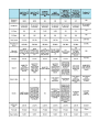
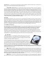
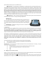
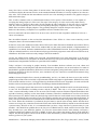
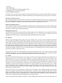
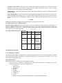
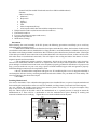
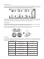
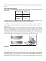
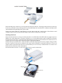
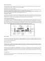
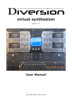
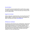
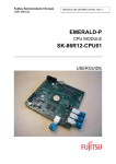
UNIT - 2
BUILDING A PC
Reasons for Building your Own PC
Anyone who has successfully built his own computer can usually rattle off a mile-long list of reasons why it is
better to build your own than to buy one at the nearest computer-chain mega store. Then again, if you talk to
somebody who has tried and failed or who has never opened up their computer, they can probably argue a
pretty convincing case for buying a manufactured model. Most People decide to build their own computer
mainly because they can put it together exactly as they want it, it is easier to repair, and it makes future
upgrades a breeze.
The real beauty of building your own computer is that you pick out exactly what you want, and you don’t have
to pay for features you don’t need. For example, if you want your Computer to double as an entertainment
center you bundle with DVD drive/sound system 5.1 dolby digital to enjoy live experience.
Another reason you might opt for building your own machine is that, when something breaks down, you are in
a much better position to fix it. You put it all together and know where everything is. If you know the problem
is with the video card, you can go directly to that card and decide what to do. If you still have a warranty on it,
you probably can get it repaired, or get a new one, for free. If not, you can choose from the wide range of video
cards available, spend as much as you see fit, then install the new one.
Another reason to build your own computer is that it will give you a great deal of flexibility when it comes time
to upgrade in a few years. Yes, even with your souped-up ultra machine, you’ll have to add memory or more
disk space to keep up with the constantly evolving software out there.
With your custom-built computer, upgrading is an simple as replacing a bad part. You take out the old stuff, put
in the new stuff, and away you go.
Shopping Around
Once you choose to build, you face another set of decisions. The first involves determining what components you
need and want in your machine and how much you are willing to spend for the whole package.
The best place to start your list is with a set of minimums. Set the bottom limits of what you will accept in terms of
components and their performance. Then set a budget. As you begin to compare prices, you may decide that you can
afford a larger hard drive or a better monitor, and you can make those adjustments before you buy.
Once you’re ready to buy, you must decide whether to purchase your equipment from your local computer store or
through a mail-order company. Each approach has its advantages.
2.1 The Basics
There are some components that you simply cannot build a computer without.
I. The CPU
The CPU, or rather microprocessor, is the heart of any computer system. The microprocessor calculates, performs
logical operations and manages data flows by reading instructions from memory and then executing them.
Abbreviation of Central Processing Unit, and pronounced as Separate letters. The CPU is the brain of the
computer. Sometimes referred to simply as the processor or central Processor, the CPU is where most
calculations take place. The most significant factor on which the overall speed of the system depends. On large
machines, CPUs require one or more printed circuit boards. On personal computers and small workstations, the
CPU is housed in a single chip called a microprocessor. Well there are various versions of the CPUs such as
80286,80486,80586 or Pentium. But the earlier three types are not available or used. The CPUs currently in the
use are Pentiums. There are various generations of these Pentium CPU’s as mentioned
The speed of a CPU is indicated in terms of Mhz. Numeric Co-Processor is nothing but the ability of CPU by which
it can perform floating-point numerical operations directly.
Internal cache memory, well the word memory indicates that more the memory more will be the speed of
the CPU.
CPUs are available basically in two types physical structures such as PGA package. All the CPUs before Pentium I
series and earlier were also available in PGA package. This Package of CPU is a chip and a set of pins coming from
its bottom. In this type of CPUs the cooling fan is separate. So before fitting the cooling fan a layer of Heat Sink
Compound along with heat sink is suggested. These CPUs are to be fitted in the ZIF sockets on the motherboard.
The SEC package of CPUs was introduced after Pentium II. This package of CPU is like an ADD-On Card in the
motherboard. It has a Single Edge of Connectors on the bottom side and a fan attached on the front side. Slot 1 is
meant for the CPUs, which come in SEC Package.
II. MEMORY
All systems have a memory hierarchy with memory at different speeds and sizes at different points in the hierarchy.
The fastest memory is known as Cache memory and is what it sounds like - memory that is used to temporarily
hold, or cache, contents of the main memory. This sort of memory is very fast but expensive, therefore most
processors have a small amount of on-chip Cache memory and more system based (on-board) cache memory.
Some processors have one cache to contain both instructions and data, but others have two, one for instructions and
the other for data. The Alpha AXP processor has two internal memory caches; one for data (the D-Cache) and one
for instructions (the I-Cache). The external cache (or B-Cache) mixes the two together. Finally there is the main
memory which relative to the external cache memory is very slow. Relative to the on-CPU cache, main memory is
positively crawling.
The cache and main memories must be kept in step (coherent). In other words, if a word of main memory is held in
one or more locations in cache, then the system must make sure that the contents of cache and memory are the
same. The job of cache coherency is done partially by the hardware and partially by the operating system. This is
also true for a number of major system tasks where the hardware and software must cooperate closely to achieve
their aims.
Main storage is also called Memory or Internal Memory (to distinguish from external memory, such as hard
drives).
RAM is Random Access Memory, and is the basic kind of internal memory. RAM is called “Random
Access” because the processor or computer can access any location in memory (as contrasted with sequential
access devices, which must be accessed in order). RAM has been made from reed relays, transistors, integrated
circuits, magnetic core, or anything that can hold and store binary values (one/zero, plus/minus, open/close,
positive/negative, high/low, etc.). Most modern RAM is made from integrated circuits. At one time the most
common kind of memory in mainframes was magnetic core, so many older programmers will refer to main
memory as core memory even when the RAM is made from more modern technology. Static RAM is called static
because it will continue to hold and store information even when power is removed. Magnetic core and reed relays
are examples of static memory. Dynamic RAM is called dynamic because it loses all data when power is removed.
Transistors and integrated circuits are examples of dynamic memory. It is possible to have battery back up for
devices that are normally dynamic to turn them into static memory.
l
l ROM is Read Only Memory (it is also random access, but only for reads). ROM is typically used to store
things that will never change for the life of the computer, such as low level portions of an operating system. Some
processors (or variations within processor families) might have RAM and/or ROM built into the same chip as the
processor (normally used for processors used in standalone devices, such as arcade video games, ATMs,
microwave ovens, car ignition systems, etc.). EPROM is Erasable Programmable Read Only Memory, a special
kind of ROM that can be erased and reprogrammed with specialized equipment (but not by the processor it is
connected to). EPROMs allow makers of industrial devices (and other similar equipment) to have the benefits of
ROM, yet also allow for updating or upgrading the software without having to buy new ROM and throw out the old
(the EPROMs are collected, erased and rewritten centrally, then placed back into the machines).
SIMM
A SIMM, or (Single in-line memory module), is a type of memory module used for Random Access Memory in
personal computers. It differs from a DIMM (the most predominant form of memory module today) in that the
contacts on a SIMM are redundant on both sides of the module.
Most early PC motherboards (8088 based PCs and XTs) used socketed DIP chips. With the introduction of 80286
based PC/ATs, which could use larger amounts of memory, memory modules evolved from the need of saving
motherboard space and to ease memory expansion. Instead of plugging in 8 or 9 single DRAM DIP chips, only one
additional memory module was needed to increase the memory of the computer. A few 80286-based computers
used (often non-standard) memory modules like SIPP memory (single in-line pin package). SIPP’s 30 pins often
bent or broke during installation, which is why they were quickly replaced by SIMMs which used contact plates
rather than pins.
The first variant of SIMMs has 30 pins and provides 8 bits of data (9 bits in parity versions).
The second variant of SIMMs—sometimes called PS/2 after the IBM line of personal computers in which it was
first used—has 72 pins and provides 32 bits of data (36 bits in parity versions). Around 1997, 72-pin SIMMs
replaced 30-pin SIMMs.
The Macintosh IIfx requires non-standard 64-pin SIMMs.
Due to the differing data bus widths of the memory modules and some processors, sometimes several modules
must be installed in identical pairs or in identical groups of four to fill a memory bank. For instance, on 80386 or
80486 systems (data bus width of 32 bits), either four 30-pin SIMMs or one 72-pin SIMM are required for one
memory bank. On Pentium systems (data bus width of 64 bits), two 72-pin SIMMs are required.
The earliest SIMM sockets were conventional push-type sockets. These were soon replaced by ZIF (Zero Insertion
Force) sockets in which the SIMM was inserted and rotated until it locked into place. To install a SIMM, the
module must be placed in the socket at an angle, then rotated (angled) into position. To remove one, the two metal
or plastic clips at each end must be pulled to the side, then the SIMM must be tilted back and pulled out. The earlier
sockets use plastic retainer clips which were found to break, so steel clips replaced them.
RAM technologies used on SIMMs include EDO and FPM.
SIMM is standardized under JEDEC JESD-21C standard.
Standard sizes available
30-pin SIMM: 256KB, 1MB, 4MB, 16MB
72-pin SIMM: 1MB, 2MB, 4MB, 8MB, 16MB, 32MB, 64MB, 128MB
l DIMM
A DIMM, or (Dual in-line memory module) comprises a series of random access memory integrated circuits.
These modules are mounted on a printed circuit board and designed for use in personal computers. DIMMs began
to replace SIMMs (single in-line memory modules) as the predominant type of memory module as Intel’s Pentium
processors began to control the market.
The main difference between SIMMs and DIMMs is that SIMMs have a 32-bit data path, while DIMMs have a 64bit data path. Since Intel’s Pentium has (as do several other processors) a 64-bit bus width, it required SIMMs
installed in matched pairs in order to use them. The processor would then access the two SIMMs simultaneously.
DIMMs were introduced to eliminate this inefficiency. Another difference is that DIMMs have separate electrical
contacts on each side of the module, while the contacts on SIMMs on both sides are redundant.
The most common types of DIMMs are:
•
72-pin-DIMMs, used for SO-DIMM
•
144-pin-DIMMs, used for SO-DIMM
•
200-pin-DIMMs, used for SO-DIMM
•
168-pin-DIMMs, used for FPM, EDO and SDRAM
•
184-pin-DIMMs, used for DDR SDRAM
•
240-pin-DIMMs, used for DDR2 SDRAM
Manufacturers: - According to the current (Indian) market the RAM available from Hyundai is considered to be
the best. Various other brands of RAM are LG, Mtek, Kingston etc.
L
REGISTERS AND FLAGS are a special kind of memory that exists inside a processor. Typically a
processor will have several internal registers that are much faster than main memory. These registers usually have
specialized capabilities for arithmetic, logic, and other operations. Registers are usually fairly small (8, 16, 32, or
64 bits for integer data, address, and control registers; 32, 64, 96, or 128 bits for floating point registers). Some
processors separate integer data and address registers, while other processors have general purpose registers that
can be used for both data and address purposes. A processor will typically have one to 32 data or general purpose
registers (processors with separate data and address registers typically split the register set in half). Many
processors have special floating point registers (and some processors have general purpose registers that can be
used for either integer or floating point arithmetic). Flags are single bit memory used for testing, comparison, and
conditional operations (especially conditional branching).
III. BUSES
The individual components of the system board are interconnected by multiple connection systems known as
buses. The system bus is divided into three logical functions; the address bus, the data bus and the control bus. The
address bus specifies the memory locations (addresses) for the data transfers. The data bus holds the data
transfered. The data bus is bidirectional; it allows data to be read into the CPU and written from the CPU. The
control bus contains various lines used to route timing and control signals throughout the system. Many flavours of
bus exist, for example ISA and PCI buses are popular ways of connecting peripherals to the system.
IV. EXTERNAL STORAGE
External storage (also called auxillary storage) is any storage other than main memory. In modern times this
is mostly hard drives and removeable media (such as floppy disks, Zip disks, optical media, etc.). With the
advent of USB and FireWire hard drives, the line between permanent hard drives and removeable media is
blurred. Other kinds of external storage include tape drives, drum drives, paper tape, and punched cards.
Random access or indexed access devices (such as hard drives, removeable media, and drum drives) provide
an extension of memory (although usually accessed through logical file systems). Sequential access devices
(such as tape drives, paper tape punch/readers, or dumb terminals) provide for off-line storage of large amounts
of information (or back ups of data) and are often called I/O devices (for input/output).
●
Hard Disk
When power to the PC is switched OFF contents of the memory is lost. It is the Hard Disk, which serves as a bulk,
non-volatile medium for storage of user files or data or applications. It’s hard to believe that not so long ago 100MB
of hard disk space was considered to be generous. Today this would be totally inadequate, hardly to install the
operating system alone. Refer to (Figure 2.1)
The PC’s upgradability has led software companies to believe that it doesn’t matter how large their application are.
As a result, the average size of the hard disk rose from 100MB to 1.2GB to 2.1GB than to 8.4GB and has reached
up to 40-80 GB in just a few years. Thankfully, as capacity has gone up prices have come down, improved a real
density levels being the dominant reason for the reduction in price per megabyte.
It’s not just the size of hard disks that has increased. The performance of fixed disk media has also evolved
considerably. When the Intel Triton chipset, EIDE PIO mode 4 was born and hard disk performance soared to new
heights, it allowed users to experience high-performance and high capacity data storage without Paying the
premium for SCSI- based system.
■ Operation: - when the computer wants to read data, the operating system works out where the data is on
the disk. It first reads the FAT (File Allocation Table) at the beginning of the partition. This tells the operating
system which sector on which track to find the data. The operating system also subdivides each sector into clusters,
so the FAT contains information as to which clusters in the sector contain the data as well. With this information, the
head can then read the requested data. The disk controller controls the drive’s servomotors and translates the
fluctuating voltages from the head into digital data for the CPU.
■ Interfaces: - The drive is connected to the computer using one of a few possible interfaces. MFM and
RLL are now obsolete, IDE is somewhat antiquated and has a problem in coping with the big modern (Gigabyte-
plus) hard disks and today’s drives use EIDE or SCSI.
■ Performance: - The performance of a hard disk is very important to the overall speed of the system- a
slow hard disk having potential to hinder a fast processor like no other system component - and the effective speed
of a hard disk is determined by a number of factors. Chief among them is the rotational speed of the platters. Disk
RPM is a critical component of hard drive performance because it directly impacts the latency and the disk transfer
rate. The faster the disk spins, the more data passes under the magnetic heads that read the data; the slower the
RPM, the higher the mechanical latencies. Hard drives only spin at one constant speed, and for some time most fast
EIDE hard disks span at 5400RPM, while a fast SCSI drive was capable of 7200RPM. In 1997 Seagate pushed spin
speed to a staggering 10033RPM with launch of UltraSCSI Cheetah drive and in mid 1998, was also the first
manufacturer to release an EIDE hard disk with a spin rate of 7200RPM.
■ Manufacturers: - Many companies manufacture the hard disks. But only three of these manufacturers
are famous in today’s market viz., Seagate, Samsung and Quantum.
● Floppy Drive.
This is the simplest part present inside the machine; I said this because it
does not require any drivers or any type of critical configuration. Even there
are no factors to be considered prior to purchase a floppy drive. Floppy disks
come simply without any other extra item such as drivers or cables etc Figure
(2.2).
Manufacturers: - The brands of floppy drives that are available in the
market are Teak Media, and Sony.
V. Sound Card
Sound is a relatively new capability for PC’s because no one really considered it when the PC was first designed.
The original IBM-Compatible PC was designed as a business tool, not as a multimedia machine, so it’s hardly
surprising that nobody thought of including a dedicated sound chip in its architecture. Computers, after all, were
seen as calculating machines; the only kind of sound necessary was the Beep that served as a warning signal. That’s
why PCs continue to require an add in board or sound card to produce decent quality sound.
The Popularity of multimedia applications over the past few years has accelerated the development of the sound
card, and the increased competition between manufacturers has led to these devices becoming cheaper and more
sophisticated. Today’s cards don’t only make games, multimedia applications sound great but with the right
software users can also compose, edit and print their own music as well as learn to play the piano, record and edit
digital audio, and play audio CDs. Extending it’s capabilities the Self Learning Sound Interactive CDs are
available.
Currently Sound Cards are available in the market along with the following things:
a)
Driver installation CD that contains drivers and utilities such as media rack.
b)
User manual for sound card
Manufacturers: - The sound cards are available in the market from various manufacturers. According our expert
opinion their ratings are as followed
1)
Yamaha (The only economical sound card which has Bass and Treble Control
2)
Creative (offering upto dolby digital 7.1 Home theatre effect)
3)
ESS.
4)
Opti.
VI. Display Card (VGA/SVGA/AGP)
Display card is the important factor to be considered because all the graphical performance of the system depends
on the display card you select. Here are some facts about the display cards.
VGA stands to Video Graphics Array. IBM introduced it on April 2, 1987. Today, the VGA card is not much used,
and usually serves as a “Spare”. VGA offers Clean images at higher resolutions. The standard VGA can produce as
many 256 Colors at a time from palette of 262144 colors. The original VGA, though, had to be at a 320x400
resolution to display this amount of color. At the standard 640x480 resolution, it was only capable of 16 colors at a
time. Also, VGA extends into the monochrome world. It uses color summing to translate color graphics using 64
different shades of gray.
This, in effect, simulates color on a monochrome monitor. VGA equires a VGA monitor, or one capable of
accepting the analog output of a VGA card. The super VGA category of video card is really rather loosely
named. It refers to a group of video cards, all with roughly the same capabilities. It does not refer to a specific
card, like VGA technically does. SVGA was developed by third party companies in order to compete with
IBM’s XGA and 8514/A display adapters. They probably thought it would be cheaper to develop new
hardware rather than try to adapt the new capabilities onto the standard VGA card.
SVGA is much more advances than VGA. In most cases, one SVGA card can produce millions of colors at a
choice of resolutions.
But, the abilities depend on the card and the manufacturer. Since SVGA is a loose term created by several
companies, there is no actual standard to SVGA.
In order to create some standard out of the chaos of SVGA, the Video Electronics Standards Association (VESA)
introduced a SVGA standard. This SVGA standard did not deal with certain methods of implementation of
capabilities, but, instead, defined a standard interface called VESA BIOS Extension. This provided programmers
with one common interface to write for instead of trying to tailor their programs to work with several SVGA cards,
all different. All SVGA cards in use today comply to the VESA standard.
At first, the VESA SVGA standard was criticized, and manufacturers were slow integrating it. At first, they
distributed the extension as a program to be loaded each and every time you booted the computer. Finally, though,
manufacturers integrated the extension as a part of their SVGA BIOS.
Today’s software is increasing in graphic intensity. Even mundane business software uses icon, charts and
animations. When you add 3D games and educational software to the equation, one can see that there is a crunch in
bandwidth for graphical information. With newer software and games getting much more graphics intensive, the
PCI bus is maxed out. In fact, the PCI bus, once considered very fast, can now be considered a bottleneck using
demanding applications.
AGP(Accelerated Graphics Port) sounds groundbreaking, and it is, no doubt, the latest craze in the need for
graphical speed. But, in the real world, it is questionable if AGP really improves performance. While PCI served us
well, and still continues to do so, it is bogged down by the demand of full screen 3D graphics. It works well for 2D
business software and most games, but intense 3D challenges the bandwidth limitations.
In theory, it can support speeds four times as fast as the PCI bus, roughly 528 Mb/second. It uses the main memory
to store all 3D information, including textures and the Z-buffer. This rids us of a prime problem of PCI
video—textures add reality to what we see on screen. The Z-buffer creates an illusion of depth. Both of these take
up loads of memory, and they use the same chunk of memory. Therefore, manufacturers were forced to choose
between textures or Z-buffers. Often, they had to design software that was weak in both areas in order to deal with
the PCI bus. With AGP, this restriction is gone. The graphics controller processes the texture data and bitmaps. In
many cases, the controller must read elements from 7 or 8 different textures and average them into a single pixel on
the screen. When this calculation is performed, the pixel must be stored in the memory buffer. Because these
textures are so large, they cannot be stored on the Video card’s buffer. With AGP, they instead are stored in the main
system memory. Because of this, it is recommended that you have a large amount of system memory in your
machine – this should be no problem due to the low prices of RAM. Intel, no doubt, took this into account when
they decided to use your RAM for graphics. To access the texture data from the main memory, AGP uses a
technique called Direct Memory Execute, or DIME. In short, this connects the memory directly to the AGP/PCI
chipset. This lets the graphics card access the textures in the main memory, which is limited only by the amount of
memory you have in your system.
Manufactures: - The brands of display cards available in the market are S3 (Trio, Virge), Sis (6215C, 6326), Trident
(9750,9850), and Cirrus Logic (5440,5446) & others.
VII. CD-ROM
Compact Disks are now the main medium for distribution of software. CDs are coated with aluminum to reflect
light and imprinted with a series of pits and flat areas. Reading these pits or flats denote 0’s or 1’s. A thin laser beam
reads the pits or flats while the disk is spinning. Light reflects from the flat surfaces, not the pits. The photo detector
reads what is reflected and sends the 0’s and 1’s to the CPU.
CD drives shine a laser onto the disk and a photo detector picks up the reflections. A pit scatters the beam, and
a land, or a flat spot, reflects the beam. This data is decoded into 0’s and 1’s and sent to the CPU. CDs use a
long spiral groove, much like a LP. This is called CLV, or Constant Linear Velocity recording. To keep up this
constant speed, special drive spinning mechanisms spin the CD slower and slower as the read/write head get
closer to the edge of the disk. Other drives, like MO drives, as well as floppy drives, use the track system, a
series of concentric circles around the disk. This track and sector system is called CAV, or Constant Angular
Velocity, recording. CDs use a long Spiral groove, much like an LP.
This is called a CLV, or constant linear velocity recording.
Currently CD-ROMs are available only with the following things:
a) 40 pin FRC cable for IDE interface.
b) 4 pin Audio cable for analog audio output to be given to the sound card.
c) Remote control for CD-ROM (this only come along with the latest models of creative CD-ROM).
d) 3V lithium battery for remote control.
e) CD-ROM driver installation Floppy.
f) CD that contains drivers for sound cards and infrasuit software (if the CD-ROM supports infra feature).
g) User Manual filled with stuff such as jumper settings and various features of CD-ROM etc.
h) Screws for fitting the CD-ROM.
Manufacturers: - CD-ROMs are available from various manufacturers such as Ceative, Acer, Samsung, Phillips,
Sony, LG etc.
VIII. DVD-Combo
The DVD writer has become the norm in many computers available today even in less developed countries. There
are many manufacturers of DVD writers today and the DVD writers are capable of writing CD-Rom, Audio CD,
Mixed mode CD containing data and music and pictures, video CD, Super video CD, and DVDs.
Most of the DVD writers come bundled with the required software for writing to DVD and making copies of CD or
DVD.
A CD or DVD has a layer of an organic dye layer or crystalline metal alloy in the recording layer of the disc. This
layer is heated by the laser in the writing head of the disk. The recorder records the information by selectively
heating the organic dye layer in the disk. The change in the reflectivity of the dye due to this heating encodes the
information so that it can be read by the by the reading laser beam.
Difference in the CD/DVD ROM and DVD-RW
The change in the recording layer will be permanent as in the CD-ROM or DVD ROMs. For the DVD+RW the
change will be in the crystalline metal alloy layer. The subsequent re-recording will re-melt the crystalline metal
alloy to the required level and the process can be repeated nearly 1000 times.
What DVD burning software does?
The software for this purpose changes the laser beam strength and makes sure that the process is controlled as per
the requirement of the work being done on the disk.
Typical DVD Burning Software Choices
In typical DVD recording software, you will find the following modes for writing to the disk.
1. CD ROM
2. Audio CD
3. Mixed mode CD
4. CD extra for data pictures and songs
5. CD copy
. video CD burning
7. Super video CD burning for burning MPEG-2 files
8. CD ROM boot for your operating system
9. DVD with MPEG-4 format
You may need to select the various modes for writing to the disk that you are going to make. Make sure that you
have all the required settings before you burn the disk otherwise the entire disk may go waste if you are not careful.
How does the software work?
The software first makes an image of the file system to be recorded and then starts the process of burning on the
disk. Any interruption in this process is the end of session. Earlier only single session could be managed and the
disk space could not be written later as the lead out from the disk was completed in one session.
Multi Session Disks Software
Later, multi session disks were developed and this made the process continuous from one session to another. In the
multi session recording you will be given option of closing the entire disk at the end of this session. This will either
close the recording or keep it open for the next step.
During Burning Process
The burning process does not require and intervention of the person recording the disk. Any ejection of disk may
change the recording parameters and make the disk suitable for use as coaster of tea cup. Therefore, do not do
anything unless software gives you the message that the recording was done successfully.
IX. Monitor
Monitors obviously display what is going on in your computer. They can run at various resolutions and refresh
rates. 640x480 is the default resolution for the Windows operating systems (this is a low resolution where objects
appear large and bulky). 640x480 just means that 640 pixels are fit across the top of your monitor and 480 up and
down. Most users prefer higher resolutions such as 800x600 or 1024x768 all the way up to 1600x1200 (and higher
for graphics professionals). The higher resolutions make objects smaller, but clearer (because more pixels are fit in
the screen). You can fit more objects on a screen when it is in a higher resolution. Larger monitors are better for
running at the higher resolutions. If you run a high resolution on a small monitor, the text may be hard to read
because of its small size, despite the clarity.
The monitor has a lot to do with the quality of the picture produced by your video card, but it doesn’t actual
“produce” the graphics - the video card does all this processing. But, if your video card is producing a bright
detailed picture and your monitor is dim and blurry, the picture will come out the same way.
X. Cabinet
The case is the metal and/or plastic box you see when you look at your computer. Most people don’t think of it as an
important part, but it is. It is the skin of the computer, so to speak. It supports the rest of your computer. The
expansion cards are held in by the motherboard, but what holds the motherboard and the drives? The case! It also
protects the system from the outside world. It is a vital component in the maintaining the temperature of the
computer. A clean case with much space inside helps the air flow through the system. Also, a closed case’s design
actually helps to funnel the air through the system over components such as the CPU. When buying a case, make
sure it is expandable. There is nothing worse than needing a new hard drive and not having any room for it. Also,
make sure the case looks good. After all, it is what you and everyone else sees every day. An ugly case can be a real
eyesore for a nice office or room.
All cases have the power switch and the reset button. Power switches come in different designs, from the push
button to the toggle switch. Older cases had a turbo button. This button’s job is outdated and the button is really
pointless on modern machines. Many think that pressing this button puts the computer in some super-duper fast
mode. Other cases had a key lock. Basically, this is a security feature that disables the keyboard so that the user
cannot use the computer until unlocked. Nobody uses this much anymore.
Cases are designed for the particular “form factor” of the motherboard to be placed in it. The slots in the back vary
in position, and other factors differ, like the power supply.
Form Factor: The two main form factors are Baby AT and ATX. Baby AT is the most popular, modeled after the
original IBM AT design, but smaller. This case requires an AT supporting motherboard and power supply. The ATX
case requires an ATX supporting motherboard. The openings in the case are built to align with the motherboard,
and the power supply is specially designed to be software controlled. Much other advancement is built into the
case, making them fancier and more expensive.
The two main types of case are Tower and Desktop. A tower is the most common, and is taller than it is wide. The
desktop is flat, designed to sit on the desk. A tower is designed to sit on the floor.
A tower case can hold many more drives than the desktop case. The desktop, though, is better for placement on the
desk, as it allows you to put the monitor on top of it to save space. Towers come in three main sizes. The full-tower is
the big one, standing two or three feet high. It can hold many drives and usually comes with a larger (higher
wattage) power supply to run them all. It is very expandable and roomy, which allows for excellent cooling. The
mid-tower is just like the full-tower, only shorter. The mini-tower is the most popular. It stands 1.5-2 feet high, and
is roomier than the desktop. Because of its size, it is ideal for placement on the desk. The desktop case’s main
advantage is the space saving design. It is not a good cooling case. Also, drives are often placed on their sides. This
is not ideal for the drive, although it works. It can also be a little annoying to have to flip the floppy disk over to stick
it in the drive.
Branded machines (like HCL, WIPRO etc.) manufacture cabinets with some extra facilities such as lock at the back
of the cabinet. They even sometimes have no screws to tighten the covers or cards all they have is some sort of
tricky locks, thus eliminating the need for a screwdriver to open them.
Currently the cabinets available in the market come along with:
a) SMPS (Switch Mode Power Supply).
b) Power Cord.
c) Internal speaker (to be connected to motherboard).
c) Motherboard mountings, screws, base studs (to be fitted at base of cabinet), extra plastic strips (to be fitted at
front panel), extra metal strips (required to be fitted at back panel).
d) Some (typically ATX) cabinets also come along with extra cooling fan fitted on the back panel.
e) Some cabinets (typically ATX) cabinets provide stickers for sticking at various places on back panel.
The factors to be considered for purchasing a cabinet are:
a)
SMPS Wattage : - Well latest standard cabinets have SMPS ranging from 220 to 250 Watts.
b) Type of Power Supply: - Currently only two types of power supplies are available viz. AT and ATX. This
must be decided on the type to motherboard that we use. Generally all new
motherboards support both types of power supplies. Older boards require AT power supply, and few latest
motherboards support only ATX power supply.
c) Front Panel Design: - The front panel of the cabinet must accommodate all the peripherals you require such
as CD - ROM, 1.22MB Floppy Drive, 1.44MB Floppy Drive, Internal Zip Drive etc.
d) Back Panel Design: - The back panel design of cabinet is very important. The typical back panel must
provide maximum of ventilation so as to keep the system cool even if air condition is not present, well but it
must even prevent dust from entering the system.
e) Door or cover for Front Panel: - The door or the cover must safeguard dust from entering into floppy drives
when system is not in use.
f) Metal cover for cabinet: - The earlier tower cabinets had a single piece metal cover for the, but the latest
cabinets have the covers in two sheets on either side of the cabinet, so it becomes easier to remove only the
sheet on one side for fault finding or upgrading purposes.
Manufacturers: - Well in the Indian market cabinets with the name KPPL are popular. The SMPS used inside
are from Kobian.
Type of Floppy Drive: - Latest cabinets have special design for Floppy drives bay which have only a fancy
shaped slot behind which floppy drive is to be fitted. Well I would personally advise not to use these cabinets
because they may cause a misalignment of button in future. While operating the button one has to be very
gentle.
l SMPS
SMPS (Switch Mode Power Supply) has got basically three types of power connectors:
Two 6 Pin connectors for AT Motherboard.
Four 4 Pin Large connectors. These 4 pin large connectors are required for many peripherals such as HDD, 1.22
FDD, CD - ROM, CPU FAN, Extra cooling fan, Internal zip drive etc. Thus sometimes the connectors provided
become insufficient, in such case Y - connectors (not the technical name in fact) female connectors at middle and
male connectors at two ends can be used.
Two 4 Pin Small connectors for 1.44 FDD.
Features
Older
New
Increased ability
SMPS Type
AT
ATX
Advanced Power
Management
Feature
Higher
Supports more
number of
devices which
extract power
from SMPS
More
Well more the
space more the
devices can be
added to machine
and also helps in
better ventilation
SMPS Wattage
Space
Less
Less
UPGRADATION NOTES
2.2 Assembling a Computer
After buying all the computer components they must be put together. This process is called Assembling. It usually
takes about fifteen minutes (installing not included). Although easy, it must be done carefully so as to avoid
unnecessary damage to the system.
Materials Required
Make sure that you have all the below materials before starting.
1. All the necessary components (Although the all the below components are preferable, not all are
necessary. Then necessary ones are marked with a *)
O Processors *
o Motherboard *
o Hard Disk *
o RAM *
o Cabinet *
o Floppy Drive *
o CD Drive *
o Cards
- Display Card (Not needed if On-board display is available on Motherboard)
2.
3.
4.
5.
6.
- Sound Card (Not needed if On-board sound is available on Motherboard)
- Modem
- Other Cards(If Any)
o Monitors *
o Keyboard *
o Mouse *
o Speakers
o UPS
o Other Components(If Any)
o Also keep the cables that came with the components close by
Philips head Screwdriver(also known as Star Screwdriver)
Flat head Screwdriver
Forceps (for pulling out jumpers and screws)
Magnetized Screwdriver
Multi meter (Testing)
Precautions
Before Starting the actual assembly of the PC System, the following precautions would help you to avoid any
mishap during the assembly process:
o While the motherboard has to be fitted at a fixed place inside the PC cabinet, the locations of add-on cards
(as and when used) and the drivers (hard disk drive, floppy disk drive, and CD-ROM drive) within the drivers bay of
the cabinet can be changed within certain limits. But it is better to place them far away from each other. (The length
of the cable provided for interconnections to the motherboard has to be taken into account, as there must be some
slack after these are installed and connected.) This will improve the cooling and reduce the chance of electromagnetic interference between them.
o The motherboard contains sensitive components, which can be easily damaged by static electricity.
Therefore the motherboard should remain in its original anti static envelope until required for installation. The
person taking it out should wear an anti static wrist strap that is properly grounded. In the absence of a proper wrist
strap, you must make one on your own, using a peeled of multi-stranded copper cable and ground it properly.
Similar handling precautions are also required for cards.
o Be sure to handle all the components with great care. If a small thing like a screw is dropped on the MB, it
can damage the delicate circuitry, rendering the Main Board useless. Make sure your hands are clean and dry. The
area of assembling is free frome loose liquid.
o Procedure
Installing Motherboard
You need to determine if the cabinethas the appropriate risers installed. Risers, or spacers, keep the motherboard
from touching the metal surfaces of the case after it is installed, avoiding a short-circuit and a wrecked computer.
Any new cabinet will include some form of riser, metal or plastic. See the Fig 2.3 for typical examples. They
may or may not be pre-installed into the case.
Keep the cabinet panel on the table and fix the motherboard on it. A gentle pressure is enough to mount the
Motherboard on it. There will be a mechanism to lock the motherboard in place. Identify its working and
mount the motherboard accordingly. Tighten the screws on the motherboard to the panel.
(Audio)
(Power
Supply)
(PCI Express)
(Mother Board
Power Supply)
(CPU)
BIOS
(Jumper Block)
(RAM)
(USB)
DIMM 0
DIMM 1
(Front
Panel)
(Front
(Power
Panel Power CPU Fan) (IDE
LED)
Cables)
(Power
Supply)
(Cabinet)
(Floppy
data Cable)
(Power Supply)
Fixing the Processor
Now gently lower the CPU into the ZIF (Zero Insertion Force) Socket. No pressure is required. If the CPU is placed
properly, it will slide into the socket. Make sure that the Number 1 pin is placed correctly. If you cannot get the CPU
to sit evenly DO NOT force it. After placing the CPU, lock the socket using the Locking lever.
Apply the IC paste that comes with the processor to the bottom of the heatsink. Only a thin layer is necessary. This
lets the heat that is produced in the processor to be conducted to the heatsink which cools it. After applying the
paste, fix the heatsink on the processor. Make sure that the locks of the heat sink are in place.
Installing RAM
Keep the RAM module in the slot in the proper way and press downwards. Be careful not to jerk the RAM while
pushing it down. See that the lock gets hold of the RAM and stay in the locked position.
The ways of inserting the RAM will vary with different kinds of RAM. There are different kinds of RAM like
SDRAM, DDRAM, RDRAM, etc. Please refer to the section on RAMS for more details.
Connections
Next, affix the cables that are provided to the necessary places on the motherboard. Be careful to fix the cables
properly and not damaging the pins or the motherboard in the process. Make sure that the red part of the IDE
cables(the no 1 pin) is in proper position.
Name of Cable
Device connector of...
No of Pins
IDE
Hard disk, CD-ROM
40
Floppy IDE
Floppy Drive
34
Power Cable For
Motherboard
From SMPS to Motherboard
6x2 in AT and 20 in ATX
Front Panel Display
Different for each
Speaker, HDD Indicator LED,
Power LED, Restart
Backside Connections
PS/2, USB, LPT, COM 1, COM 2, etc
Different for each
Card Connectors
CDROM Audio cable, Onboard display to
backside cable, etc
Different for each
Besides the cables that are shown here there are other cables like Processor Fan power supply, Power supply
for devices like HDD, FDD, CD-ROM etc which are not connected to Motherboard, etc. All must be connected
properly.
Pin Configuration on Motherboard
There are many places to fix cables in the motherboard.The following are the pin numbers for all the slots on the
motherboard.
Device/Slot Name
No. Of Pins
LPT
25
COM
9
IDE
40
IDE Floppy
34
Now fix the motherboard to the Cabinet or the Case. Place your mother board inside the case and fasten it in. Every
Case fastens mother boards in different ways. Some use plastic pegs, some use metal screws.
Their might be metal coverings covering the holes in the computer case were the parallel ports and serial ports on
the mother board should poke through. Poke those out with a screw drive so you can fit the mother board in
snuggly. Make sure that all the connectors that come out of the motherboard is in its correct places on the back.
Expansion Slots
Now the add-on cards must be inserted in the expansion Slots Insert your Video Card if it is not onboard. There are
presently about 3 different forms of slots on your mother board - PCI, ISA, and AGP. Video Cards are presently
made for all 3 of them. AGP stands for “Accelerated Graphics Port” Video Cards made for this slot are generally
more high tech/performance. AGP slots more than likely is the only small, brown, slot on your mother board. PCI
you probably have the most of these their white and little longer than AGP. ISA, these are long and black. Insert
your Video Card and snug it in there firmly. Make sure that the other side of the card can be come out of the
motherboard’s backside. Screw the card in that place. Similar fit the other cards in its respective places.
Floppy Drive
Ensure that one of the 3.5-inch bays in your case is open. If your case came with rails for the floppy drive, attach
them to the sides of the drive and slide the drive into the front of the computer until it clicks into place. Rails are
small metal pieces which clip or screw on to the sides of the drive and allow it to be inserted and removed from the
case with minimal effort.
Otherwise, slide the drive into the front of the computer until the faceplate of the floppy drive is flush with the front
bezel of the case and the screw holes along the side of the drive line up with the case. When everything lines up,
screw the floppy drive in securely on both sides.
Plug in the power cable (see Fig 2.6) carefully, since it is quite possible to miss one of the connectors, which will
36 PIN CONNECTOR
Ensure that the power connector is correctly lined up with all 4 connectors. The floppy (data) cable is keyed to only
fit one way. Note that it is keyed the opposite way to the IDE hard drive and CD drive, so that the red stripe on the
cable should be facing the floppy drive power cable.
Floppy drive cables (IDE) are solid ribbon on one end, and the other has a small section of the ribbon cut and
twisted around. Ensure you only attach the floppy cable as shown in the picture to the right.
Installing Hard Disk
Ensure that the hard drive is set up to be the master drive on its IDE cable. Each IDE cable can support up to two
IDE devices, such as hard-drives, CD-drives, Zip Drives, etc., but in order for this to work, one IDE device must be
designated as a master device, and one must be designated as a slave device. You cannot have two master devices or
two slave devices on a single cable. This must be later configured in the BIOS.
Examine the top of your hard-drive. There should be a chart there depicting the necessary jumper settings to make
the drive a master or slave device. Otherwise, the chart will be somewhere on the body of the drive. The set of
jumpers will be on the back end of the drive. Ensure that they are set correctly to enable the drive as a master. You
may need a set of tweezers to move the jumpers.
Insert the hard drive into the 3.5" drive-tray and screw it in securely on both sides.
Primary
Slave
Magnetic Disk
Optical Reader
Motor
Connect the Cable to the device and on the other hand to the pri master connector on the motherboard.
Installing Optical Drive (DVD/CDROM)
Ensure that at least one full sized 5.25" bay is open in the case. Examine the jumper settings on the top of the drive,
as you did with the hard-drive. Ensure that the drive is set to ‘master’. If your case came with rails, screw them to
the sides of the CD drive and insert it into the front of the case until it clicks into place.
Otherwise, slide the drive into the front of the computer until the faceplate of the drive is flush with the front bezel
of the case and the screw holes along the side of the drive line up with the case. Then, screw it in securely on both
sides. Attach the power cable (same as the hard-drive power cable) to the drive. Attach
your secondary IDE cable to the drive. Note that generally this should be a regular 40-wire IDE cable, not the 80wire UDMA IDE cable that is used for the hard-drive. Some DVD drives will use the 80-wire cable, however.
Set the jumper on the CD-ROM drive. Here you have a choice. You can either:
●
Attach the CD-ROM to IDE connector 1 and make the CD-ROM a slave. In this case, you will set the
jumper on the CD-ROM to “Slave” and attach the CD-ROM drive to the same IDE cable as the hard drive.
Or,
●
Attach the CD-ROM to IDE connector 2 and make the CD-ROM a master. In this case you will set the
jumper on the CD-ROM to “Master” and attach the CD-ROM drive with a separate cable to IDE slot 2. In
order to use this method, you will need a second IDE cable. Connect the Sound Cable of the CDROM to the
Sound Card so that the Audio CDs can work properly.
Power Supply
There are two main kinds of motherboards and Cabinets available today with reference to Power Supply - AT and
ATX. The have different connectors.These wires come from the SMPS of Cabinet. The figure on the right shows
the Power cables coming out of the SMPS.
Different Types on Power Supply Connectors
Power supply Type
AT
ATX
Power Connections
Identify the type of power supply and insert it into the right place. The AT cables must be connected in such a
way that the black cables of both plugs with come together.
Final Connections in the Cabinet
Connect the wires coming out from behind the face of your computer case to your mother board. They control the
on, off, reset, hard disk activity, and power switch. Every mother board is different.
Refer the manual with your mother board. Most specify with 2 or 3 character paraphrases like “PWR SWT” which
means Power Switch and “RST SWT” which means Reset Switch, etc.
Closing the Cabinet
After all the connections are made inside the Cabinet, double-check all the wiring. Make sure all connections are
firmly attached, and ensure that no wires are running close to the top of the CPU heat sink fan. Then close the
cabinet and screw it tight. Set it in an upright position (assuming it is a tower type cabinet).
Connecting other peripherals
Now plug the data cable of the monitor to the display card. It will be marked on the back of the cabinet. If not, refer
the manual to see where it is. Connect Keyboard, Speakers, Mouse to the back of the cabinet in the correct places.
See that the Mouse is connected properly. If it is a PS/2 Mouse it must be connected to the PS/2 port. If it is a USB
mouse, USB port must be used. Similarly for the COM mouse. Connect all other peripherals that you may have like
Printer, External Modem, UPS, etc. to the back of the cabinet in their respective places.
PARALLEL
PORT (LPT)
LAN
MOUSE (PS 2)
KEYBOARD
(PS 2)
SERIAL( COM )
SVGA
USB
MIC
Power Cables
After all these connections, connect the power cable of the Monitor to its place. Then plug in the power cable into
its jack. Give the other end to a plug nearby. If a UPS is available, plug the power cable to the UPS and the power
cable of the UPS to the Power plug.
Powering the System
Plug in the power cord and switch the power supply switch to the on position. Press the power button. If everything
is connected as it should be, all system fans should start spinning, you should hear a single beep, and after about 2-5
seconds the computer start to boot.
Depending on the manufacturer of the Motherboard, you may get a splash screen, or just a memory check. The
system will then halt with an error because we have yet to install an operation system. Now check the front LEDs to
see if you plugged them in correctly. Also test the reset button. Power off and fix the LEDS if there are any
problems.
Configurations
At the first screen press the Delete key to enter the BIOS setup. Review the BIOS settings. Here are a few that you
may want to pay attention to:
·
·
·
Time and date.
IDE devices - Hardisk and Floppy Drive.
Boot Order.
Finished
If there are no troubles, the system is ready. The operating system can be installed now. If some problems have
appeared, read the troubleshooting guide for instructions to solve the problem.
2.3 Operating System
As we know computer comprises of various components such as input device, storage device, output device and
Microprocessor. All these various components together make a computer system. If you have to utilize this system,
all parts have to be properly managed. By now we are aware that the computer can understand only machine
language. Le.; 0' s and l’ s and the user can communicate only through human language. Therefore, there is a need to
manage the basic hardware resources and provide a hospitable interface to users and their programs. This is done
by special system software known as operating System. It has bridged the gap between the user and the computer.
We can say that the Operating System is a software program that controls the event management (processing) and
hardware associated with a computer (operating system is the first piece of software loaded into memory when a
computer starts. The job of an operating system is to orchestrate the various parts of the computer — the processor,
the on-board memory, the disk drives, keyboards, video monitors etc. — to perform useful tasks. The operating
system is the master controller of the computer, the glue that holds together all the components of the system,
including the administrators, programmers and users. When you want the computer to do something for you, like
start a program, copy a file, or display the contents of a directory, it is the operating system that must perform those
Tasks for you. More than anything else, the operating system gives the computer its recognizable characteristics.
It would be difficult to distinguish between two completely different computers, if they were running the same
operating system. Conversely, two identical computers, running different operating systems, appear completely
different to the user. It is the operating system that launches/starts other software programs such as word
processors, spreadsheets, databases, paint programs, web browsers etc.
On Intel/IBM compatible computers, possible operating systems inc1ude DOS, Windows 3.1, Window 95,
Windows 98, Windows NT 4.0, OS2 and Linux
■ DOS is an old (early 80' s) command line operating system, which requires the user to memorize and enter
all commands from the command prompt.
■ Windows 3.1 (late 80’s) was Microsoft’s first attempt at a Macintosh-like Graphical User Interface (GUI).
This interface allowed:
(1) Programs to be launched by double-clicking icons with a mouse.
(2) Files to be copied by drag and drop.
(3) Much easier copy & paste.
The Windows 3.1 operating system was a 16-bit operating system.
■ Windows 98, and Windows XP are the current state-of-the-art 32 bit operating systems. They have greatly
enhanced the GUI and have proven to be both significantly, more powerful and significantly more reliable
than the Windows 3.1 operating system.
■ OS2 began as a joint venture between IBM and Microsoft. IBM finished and marketed this operating
system. It is not used extensively today. There are a few business applications still running on this
operating system.
■ Unix was created in the late 1960s, in an effort to provide a multi-user, multitasking system for use by
programmers. The philosophy behind the design of UNIX was to provide simple, yet powerful utilities
that could be pieced together in a flexible manner to perform a wide variety of tasks. The UNIX operating
system comprises of three parts: The kernel, the standard utility Programs and the system configuration
files.
■ Linux is a freely distributed UNIX operating system for the Intel architecture. Linux has all of, the utilities
to provide printer service, ftp service, network file service, web page service, mail service and Internet
service to a host of computers. The current version of Linux is Red Hat Linux 7.0.
2.4 Boot-up Process
The term “boot” comes form the idea of lifting yourself up by your own bootstraps. Bootstrapping is necessary
because the PC has to have some way of bringing all of its components to life long enough to accomplish the goal of
loading an Operating System, so that, it can process you commands.
I. BIOS bootstrap
BIOS handles this step prior to the actual boot:
■ Performs POST (Power On Self Test). POST detects and tests memory, ports and basic devices.
■ Identifies and configures Plug and Play devices. If present, tests them.
■ Locates bootable partition on the hard drive.
■ Loads the MBR (Master boot record) and the partition table for the bootable drive, and executes the MBR.
II. Master boot record (MBR) and boot sector.
■ After MBR finds the bootable partition on the hard disk, it passes control to the boot sector in that partition.
The partition contains the, boot program and a table of disk characteristics and properties. The root
directory is located, and IO.SYS is executed. In Windows, it takes over the functions of both IO.SYS and
MSDOS.SYS from previous versions of MS-DOS.
Real-mode boot
■ MSDOS.SYS is checked for boot configuration parameters. MSDOS.SYS does not perform the same
function as in previous versions of DOS. In Windows, MSDOS.SYS is a text file where you can control
certain operations in the boot process.
■ “Starting Windows 95/98 is displayed” Default time is 2 seconds
■ LOGO.SYS is displayed.
■
If DBLSPACE.INI is present, DRVSPACE.BIN is loaded.
■
SYSTEM.DAT is checked and loaded. If not present, the backup SYSTEM.DAD will be loaded.
Whichever loads, it will update the other.
■
■
■
If system detects double buffering is necessary, it is loaded.
Based on detected hardware, a hardware profile is loaded and the user is prompted to choose one.
IO.SYS reads CONFIG.SYS, if it exists, and processes its commands
(Note: in DOS, SYSINIT told MSDOS.SYS to load COMMAND.COM here. COMMAND.COM was
responsible for:
1. Further extension to input/output functions and is loaded into memory with the BIOS and becomes part of
the Operating System.
2. Internal DOS Commands
3. Used once and then is discarded to search for AUTOEXEC.BAT)
4. IO.SYS reads AUTOEXEC.BAT, if it exists, and processes its commands.
III. Real-mode configuration
■ AUTOEXEC and CONFIG are not necessary with Windows.
■ If CONFIG.SYS does not exist, windows will automatically load HIMEM.SYS IFSHLP.SYS, and
SETVER.EXE and several environment variables. CONFIG.SYS will override these defaults.
IV. Protected-mode boot
■ WIN.COM is automatically executed after AUTOEXEC.BAT is run.
■ WIN.COM loads VMM32.VXD and any virtual devices referenced in the registry and SYSTEM.INI that
are not already a part of VMM32.VXD.
■ Processor is switched into protected mode and virtual device drivers are initialized.
■ The core Windows Kernel, GDI and user libraries are loaded along with the Explorer shell and network
support (if Present).
■ Any programs in the start-up group are executed.
■ Run any programs located at HKEY LOCAL MACHINE\MICROSOFI\CURRENT VERSION\RUN
ONCE.
2.5 BIOS
BIOS, in computer science, acronym for Basic Input/Output System, a set of routines that work closely with the
computer hardware to support the transfer of information between elements of the system, such as memory, disks,
and the monitor. On IBM and compatible computers, the BIOS, or ROM BIOS, is built into the machine’s readonly memory (ROM). Although critical to performance, the BIOS is invisible to computer users. The BIOS can,
however, be accessed by programmers.
The interaction between the input and output hardware is controlled by software called the Basic Input Output
System software (BIOS).
What is BIOS?
BIOS stands for Basic Input/Output System of which there are several in a system such as Video BIOS which
controls the interface between the video card and the computer. However, we are concerned with the System BIOS,
which is a collection of assembly language routines that allow programs and the components of a PC to
communicate with each other at the hardware level. It therefore works in two directions and is active all the time
your computer is switched on, although these days it is bypassed by almost everything, typically anything 32-bit in
Windows. Software doesn’t have to talk to a device directly; it calls a BIOS routine, which does the job instead.
Think of the BIOS as a mini operating system. So can also be called Basic Initial Operating System. On an IBMcompatible PC, you will find the BIOS embedded into a EEPROM on the motherboard, together with hard disk
utilities and a CMOS setup program. The BIOS informations are stored in a CMOS chip, which is kept under
constant voltage supply by the computer backup battery. The typical backup battery is numbered CR 2032. This
way the informations contained in the CMOS are always alive even if the computer power is turned OFF.
PC and motherboard manufacturers make their own BIOSes (such as Compaq, HCL, and ACER etc.), but most
tend to be based on code supplied by third party companies, the most well known of which are Award, American
Mega trends (AMI). The AMI, Award however, is probably the only ones that allow you past the standard CMOS
setup.
Utilities that come with the BIOS, particularly diagnostic; POST (Power On Self Test) and low-level format
routines for the hard disk. The main menu to the BIOS setup may contain the following heading: HARD DISK
UTILITY or HDD LOW LEVEL FORMAT. It allows you to low-level format the drive attached to your computer.
DO NOT USE IT TO LOW LEVEL FORMAT AN IDE DISK.
After the assembling the system and prior to the software installation the first thing you have to do as soon as you
boot the machine is set the CMOS.
2.6 BIOS Features Setup
Anti. Virus Protection Enabled When this option is enabled the BIOS will monitor the boot sector and the partition
of the hard disk drive for any attempt at modification. If a attempt is made, the BIOS will halt the system & a error
message will appear.
Disable This is recommended so that when you run any diagnostic programs that attempt to access the boot sector
neither the system halts nor the error message is displayed.
CPU Internal Cache This option speeds up memory access by utilizing the cache memory present inside the CPU,
however it depends on CPU Chipset/design. However the default value is Enable.
External Cache This option speeds up memory access by utilizing the external cache memory present on the
motherboard, however it depends on motherboard Chipset/design. However the default value is Enable.
Quick Power On Selfl’est This option speeds up POST by bypassing few tests/sub-routines. The default value is
Enable.
Boot Sequence This option specifies the sequence in which the BSL searches for the OS. The default value is
A,C,SCSI. Optionally if the OS resides on the Hard Disk the value can be set to C Only thus minimizing the search
time.
Swap Floppy Drive This option is to be enabled if two floppy drives are present & they are to be swapped. Typically
the value is set to Disable.
Boot Up Floppy Seek During POST the BIOS will determine if the floppy disk drive installed is 40 tracks (360k) or
80 tracks (720k, 1.22M, 1.44M). Typically this value is to set Disable so that POST doesn’t waste time in
determining the type of floppy drive.
Boot Up Num lock Status This option specifies the default state of numeric keypad. By default the value is ON (i.e.
the numeric keypad is numeric keys). Else when set to OFF the numeric keypad is arrow keys.
Boot Up System Speed This option specifies the speed at which the system boots. The default is set to high.
Gate A20 Option This entry allows you to select how Gate A20 is handled, the default value is Fast.
Typematic Rate Setting This determines if the typematic rate is to be used. When Disabled, continually holding
down a key on your keyboard will generate only one key instance.
Typematic Rate(Chars/Sec) When the typematic rate is enabled, this section allows you select the rate at which the
keys are repeated. The values allowed are 6,8,10,12,15,20,24,30 characters per second
Typematic Delay(Msec) When the typematic rate is enabled, this section allows you select the delay between when
the key was first depressed and when the acceleration begins. The values allowed are 250, 500, 750, 1000 msec.
Security Option This category allows you to limit access to the system and Setup, or just to Setup. When set to
System the System will not boot and access to Setup will be denied if the correct password is not entered at the
prompt. If set to Setup the System will boot, but access to Setup will be denied if the correct password is not entered
at the prompt.
IDE Second Channel control This option allows you to enable or disable the second channel IDE controller.
Default value is Enable.
PS/2 function control This option specifies if the onboard PS/2 controller is to be enabled or disabled . The default
value is Enable. You can Disable this if you don’t have any PS/2 devices attached to the system thus reducing load
on the System.
PCI/VGA Palate Snoop This option specifies whether the MPEG ISANESA VGA card can work with PCIIVGA
card. The default value is Disable.
Assign IRQ/or VGA When this option is enabled system will assign an IRQ for VGA. The default is Enabled. This
can also be Disabled so that VGA will not occupy an IRQ, thus releasing it free for other usage (typically LAN card
etc.)
OS select/or Dram> 64MB This option allows you to access the memory over 64MB in OS/2. The default value is
Non OS2.
Video BIOS shadow This option will determine if the video BIOS will be copied to RAM. Setting this f’ to Enable
will increase the video speed.
C8000 - CBFFF The default value is Disable. This is to be set Enable only if XT i.e. Non-ATA hard disk drives are
present.
CCOOO - CFFFF The default is Disable. This is to be set Enable only if EGA card is present.
DOOOO - D3FFF Enable.