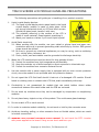
1
TC51900 CONTROLLER USER MANUAL Revised August, 2011 www.tvielectronics.com 2211 Rayford Rd., Ste. 111-332 Spring, TX 77386 281-408-4051 281-408-4052 User Manual August 2011 THIS PAGE INTENTIONALLY LEFT BLANK Copyright © 2004-2011, TVI Electronics LLC. IMPORTANT NOTICE TVI Electronics shall not be liable in any action against it in any way related to the products or software for any loss or damages, whether non-specified direct, indirect, special, incidental or consequential (including downtime, loss of profits or goodwill) regardless of the legal theory asserted. TVI Electronics reserves the right to make corrections, modifications, enhancements, improvements, and other changes to its products and services at any time and to discontinue any product or service without notice. Customers should obtain the latest relevant information before placing orders and should verify that such information is current and complete. All products sold by TVI Electronics are subject to company's terms and conditions of sale supplied at the time of order acknowledgment. User is responsible for determining whether the TVI Electronics products and software are fit for User’s particular purpose and suitable for its method of production, including intellectual property liability for User's application. Copyright © 2004-2011, TVI Electronics LLC. WARRANTY TVI Electronics warrants performance of its hardware products to the specifications applicable at the time of sale in accordance with TVI Electronics’ standard warranty. All TVI Electronics products have been manufactured to your company's or your own specifications as a part for use in your company's or own general electronic products. It is guaranteed to perform according to delivery specifications. This evaluation board being sold by TVI Electronics is intended for use for ENGINEERING DEVELOPMENT OR EVALUATION PURPOSES ONLY. We cannot take responsibility if the product is used in medical devices, nuclear power control equipment, aerospace equipment, fire and security systems, or any other applications in which there is a direct risk to human life and where extremely high levels of reliability are required. 1. We cannot accept responsibility for any defect, which may arise from additional manufacturing of the product (including disassembly and reassembly), after product delivery. 2. We cannot accept responsibility for any defect, which may arise after the application of strong external force to the product. 3. We cannot accept responsibility for any defect, which may arise due to the application of static electricity after the product has passed your company's acceptance inspection procedures. Customers are responsible for their products and applications using TVI Electronics components. To minimize the risks associated with customer products and applications, customers should provide adequate design and operating safeguards. Copyright © 2004-2011, TVI Electronics LLC. TOUCH SCREEN LCD MODULE HANDLING PRECAUTIONS The following precautions will guide you in handling of our product correctly: 1. Liquid crystal display devices: 1.1. The liquid crystal display device panel used in the liquid crystal display module is made of plate glass. Avoid any strong mechanical shock on LCD and touch screen. Should the glass break, handle it with care. 1.2. The polarizer adhering to the surface of the LCD is made of a soft material. Guard against scratching it. 1.3. Wash your hands or clothes if you touch liquid crystal! 2. Avoid Static electricity! 2.1. When working with the module, use your naked or gloved hand and wear nonconductive work suit to prevent generating static electricity by friction. ESD ground straps should be utilized. 2.2. Be sure to ground any electrical appliances you may be using, such as soldering iron, cutting pliers, tweezers, etc. 2.3. Floors, doors, and work tables must be grounded to discharge electricity. 3. When the LCD module alone must be stored for long periods of time: 3.1. Protect the modules from high temperature and humidity. 3.2. Keep the modules out of direct sunlight or direct exposure to ultraviolet rays. 3.3. Protect the modules from excessive external forces. 4. Use the module with a power supply that is equipped with an over current protector circuit, since the module is not provided with this protective feature. 5. Do not ingest the LCD fluid itself should it leak out of a damaged LCD module. Should hands or clothing come in contact with LCD fluid, wash immediately with soap. 6. Conductivity is not guaranteed for models that use metal holders where solder connections between the metal holder and the PCB are not used. 7. Do not stack up modules since they can be damaged by components on neighboring modules. 8. Do not place heavy objects on top of the product. This could cause glass breakage. 9. Do not scratch LCD or touch screen! 10. In order to maintain module reliability, do not touch or hold by the connector area. 11. Avoid any bending, pulling, or other excessive force on flexible cables, which can result in broken connections. 12. WARNING: HIGH VOLTAGE! ELECTRICAL SHOCK HAZARD! Do not touch the CCFL inverter with power applied to the board. Doing so can shock and burn you. Copyright © 2004-2011, TVI Electronics LLC. PREFACE About This Manual This user's manual describes the function and operation of the TC51900 controller Firmware rev 1.0 and higher. This manual will help you quickly set up the touch screen controller evaluation board and its accompanying software, so that you can rapidly test and evaluate their usefulness for your application. If You Need an Assistance If you have any questions about this evaluation board, feel free to e−mail TVI Electronics Support Team at [email protected]. Include the product name in the subject heading. Copyright Copyright © 2011, TVI Electronics, LLC. All rights reserved. TVI Electronics reserves the right to make changes and improvements to its product without notification. Trademarks Windows is a registered trademark of Microsoft Corporation. OPTREX is a registered trademark of Optrex Corporation. Notice to Users When a system failure may cause serious consequences, protecting life and property against such consequences with a backup system or safety device is essential. The user agrees that protection against consequences resulting from system failure is the user's responsibility. This device is not approved for lifesupport or medical systems. Copyright © 2004-2011, TVI Electronics LLC. CONTENTS 1. FUNCTIONS AND STRUCTURE........................................................................................................ 1 1.1. GENERAL ............................................................................................................................................. 1 1.2. FEATURES ............................................................................................................................................ 1 1.2.1. RS-232 communication interface with seven programmable baud rates ............................... 1 1.2.2. 8Mbit external flash memory .................................................................................................. 1 1.2.3. Touch screen controller ............................................................................................................ 1 1.2.4. AVRISP interface ...................................................................................................................... 1 1.2.5. Draw line/rectangle/circle ....................................................................................................... 1 1.2.6. Voltage regulator ..................................................................................................................... 2 1.2.7. Hardware contrast adjustment................................................................................................ 2 1.2.8. Buzzer ....................................................................................................................................... 2 1.2.9. Fonts ......................................................................................................................................... 2 1.2.10. 180° screen rotation................................................................................................................. 2 1.2.11. Expanded LCD header .............................................................................................................. 2 1.2.12. CCFL inverter ............................................................................................................................ 2 1.2.13. Firmware update...................................................................................................................... 2 1.3. POWER REQUIREMENTS ......................................................................................................................... 2 2. GETTING STARTED ........................................................................................................................ 3 2.1. 2.2. 2.3. 3. HARDWARE CONNECTION ....................................................................................................................... 3 POWER UP .......................................................................................................................................... 3 QUICK START ....................................................................................................................................... 4 OPERATION .................................................................................................................................. 5 3.1. TC51900 CONTROLLER JUMPERS AND SWITCHES ...................................................................................... 5 3.1.1. Serial Communication .............................................................................................................. 6 3.1.2. Baud Rate Settings ................................................................................................................... 7 3.1.3. Expanded LCD Header .............................................................................................................. 7 3.1.4. Contrast Regulation ................................................................................................................. 8 3.1.5. Firmware Update ..................................................................................................................... 8 3.2. TC51900 COMMANDS LIST ................................................................................................................... 9 4. POWER CONSUMPTION & PHYSICAL DIMENSIONS ...................................................................... 11 4.1. 4.2. MODULE POWER CONSUMPTION ................................................................................................. 11 TC51900 CONTROLLER PHYSICAL DIMENSIONS ........................................................................................ 11 Copyright © 2004-2011, TVI Electronics LLC. FIGURES Figure 2-1 Hardware Connection ................................................................................................................... 3 Figure 2-2 Default Software Screen ................................................................................................................ 4 Figure 3-1 TC51900 Controller Board Layout ................................................................................................. 5 Figure 3-2 PC to TC51900 Controller Connection ........................................................................................... 7 Figure 3-3 MCU to TC51900 Controller Connection ....................................................................................... 7 Figure 3-4 J1 PIN Configuration ...................................................................................................................... 8 TABLES Table 3-1 Jumpers ........................................................................................................................................... 6 Table 3-2 Headers ........................................................................................................................................... 6 Table 3-3 Connectors ...................................................................................................................................... 6 Table 3-4 Switches .......................................................................................................................................... 6 EXAMPLES Example 2-1 Default Power Up Screen ........................................................................................................... 3 Copyright © 2004-2011, TVI Electronics LLC. 1. FUNCTIONS AND STRUCTURE 1.1. GENERAL The TC51900 is an intelligent LCD controller with an integrated touch screen control that supports Optrex F-51900 320x240 CSTN Transmissive Color Graphic LCDs. This controller allows user to individually control each display pixel. This independent pixel control allows user displaying both text and graphics simultaneously. The TC51900 utilizes ATMEGA325 microcontroller, S1D13706 color/monochrome LCD graphics controller and external 8Mbit serial flash. The device can be used as an “intelligent” LCD controller or as stand-alone controller. There is enough of flash and RAM memory in the controller on board to incorporate additional graphical commands or to customize the firmware for particular tasks. 1.2. FEATURES 1.2.1. RS-232 communication interface with seven programmable baud rates The serial parameters for communication between the TC51900 controller and the host are, as follows: Baud Rate: 9600, 14400, 19200, 28800, 38400, 57600, or 115200 bps (default) Parity: None Data Bits: 8 Stop Bits: 1 1.2.2. 8Mbit external flash memory TC51900 has 8Mbit of flash memory for fonts, bitmaps, and images storage. The external flash memory is capable to save up to 12 full screen images. A utility program allows user to save 320x240 pixels bmp, jpg or gif patterns to memory. 1.2.3. Touch screen controller The touch screen controller can operate in one of these modes: 1) send raw X and Y coordinates of touch screen contact location, or 2) send digits (if used as a keypad) to host microprocessor or PC. In Keypad Mode the touch screen is divided into 36 rectangles. The controller sends decimal numbers from 1 to 36 accordingly. The TC51900 controller is calibrated for touch screen. 1.2.4. AVRISP interface AVRISP (In-System Programmer) interface allows user to program own code into microcontroller, AVRISP device is required. 1.2.5. Draw line/rectangle/circle The TC51900 controller simplifies drawing of horizontal, vertical and skew lines and shapes, such as rectangles and circles. 1 1.2.6. Voltage regulator The TC51900 has a built-in voltage regulator with input 7 - 15 VDC, connector J9 or J8 optional. 5V power may be applied to J7 eliminating the need for an onboard voltage regulator. 1.2.7. Hardware contrast adjustment The LCD’s contrast setting can be adjusted by rotating the contrast adjust potentiometer R3 on TC51900 controller board. 1.2.8. Buzzer The TC51900 controller has a built-in buzzer for sound producing. 1.2.9. Fonts The TC51900 controller supports 2 user-selectable fonts. Maximum font size is 26 pixels high. Use our utility program to convert and save system fonts to the controller flash memory. 1.2.10. 180° screen rotation The TC51900 controller allows 180° screen rotation. 1.2.11. Expanded LCD header This optional header provides an access to all available LCD control signals from S1D13706 LCD controller. 1.2.12. CCFL inverter The TC51900 controller has a built-in high voltage inverter for CCFL backlight. 1.2.13. Firmware update The TC51900 controller’s firmware can be updated through the serial port. 1.3. POWER REQUIREMENTS Power to the TC51900 is derived from the external power supply through J7, J8 or J9 connectors. Voltages of 7 - 15 VDC must be supplied through J9 or J8 connectors. Since it is regulated on the TC51900, this input voltage does not need to be regulated as long as it falls within this range. Voltage of 5 VDC must be supplied through J7 and should be regulated. Powering up the controller from J7 requires moving a jumper from J11#2 to J11#3. CAUTION: Do not reverse the polarity on the power input. Doing so will permanently damage the controller board. 2 2. GETTING STARTED This chapter guides you through the hardware connection, powering up the TC51900 controller and setting up the software for initial testing. 2.1. HARDWARE CONNECTION Carefully open the LCD connector latch J4 by pulling the brown latch upwards. Insert the flat data cable contacts side up into the connector being sure the cable is fully seated, push the latch back in being sure the cable is pushed all the way in. Insert the backlight cable into connector J6. If you have a touch screen carefully pull the latch on connector J5 out. Insert the touch screen cable into J5 being sure it is seated, push the latch back in. Figure 2 -1 Hardware Connection 2.2. POWER UP Connect a power supply to J9 power jack; make sure the polarity is correct. The controller will beep and display a power up screen #1 each time the unit is powered up. The power up screen can be customized through QVGA Control Manager software. The factory default will show TVI Electronics logo and current controller firmware revision as shown on Default Power Up Screen below. Example 2 -1 Default Power Up Screen 3 2.3. QUICK START Install the QVGA Control Manager software on your PC. A serial connection is required between the TC51900 controller board and a personal computer in order to communicate with the controller. A regular DB9 connector on board allows communication with PC through the standard serial cable. TVI Electronics offers this cable as part number DB9MF. Once the connection with the TC51900 controller is established, launch the software on your PC. Select COM Port, Baud Rate (default 115200) and click Connect. Now you may begin using the software to evaluate the TC51900 controller board. Figure 2 -2 Default Software Screen 4 3. OPERATION This chapter describes each function of TC51900 controller. 3.1. TC51900 CONTROLLER JUMPERS AND SWITCHES Figure 3 -1 TC51900 Controller Board Layout J2 J6 J5 J4 J1 J10 J13 S1 J11 J8 J7 J9 J12 5 Table 3 -1 Jumpers Reference Designator Function J10 Serial communication through RS232 Serial communication through Atmega325 UART ON OFF 3.1.1 Default baud rate (115200bps) ON 3.1.2 Power through external 7-15 VDC power supply Power through external 5 VDC power supply ON ON 1.3 J11 Setting Subsection Table 3 -2 Headers Reference Function Designator J2 AVRISP Interface J1 Optional S1D3706 LCD Output Table 3 -3 Connectors Reference Designator J4 J5 J6 J7 J8 J9 J12 J13 Function F-51900 LCD Interface Touch Screen Connector F-51900 LCD Backlight Connector Optional External 5VDC Input Optional External 7 – 15 VDC Input External 7 – 15 VDC Input RS232 DB-9 Connector Optional RS232 DB-9 Connector Table 3 -4 Switches Reference Function Subsection Designator S1 Programming 3.1.5 3.1.1. Serial Communication A standard RS232 serial interface is implemented to communicate with the host controller or the PC. This requires installation of the jumpers on J10 (Factory Default). Use J13 as an optional RS232 connector. 6 Figure 3 -2 PC to TC51900 Controller Connection A serial TTL interface is supplied at J10. For TTL interface, remove the jumpers on J10 header, see jumpers configuration on page 13. Use J10 as a header to connect TXD, RXD, and GND from external application. Figure 3 -3 MCU to TC51900 Controller Connection 3.1.2. Baud Rate Settings The baud rate is user defined (default is 115200 bit/sec). It is set by a command and stored in the flash memory. In order to change the default baud rate remove jumper J11#1 prior to sending the command. 3.1.3. Expanded LCD Header This optional header provides an access to all available LCD control signals from S1D13706 LCD controller. 7 Figure 3 -4 J1 PIN Configuration 3.1.4. Contrast Regulation The TC51900 controller has a trimmer potentiometer R3 for contrast adjustment. If you are not satisfied with the default contrast settings, use R3 to adjust the settings. 3.1.5. Firmware Update TC51900 controller supports firmware updates. The firmware can be updated through the QVGA Control Manager utility, which is included with the product and also can be downloaded from http://www.tvielectronics.com. The new firmware for the TC51900 controller can be downloaded at http://www.tvielectronics.com. 8 3.2. TC51900 COMMANDS LIST The TC51900 controller requires 2 bytes command (address) and data. Every X coordinate requires 9 bit address; first byte is MSB + second byte. Y coordinate is 0 - 239. Color is 0 – 255. Text is ASCII number for the character. Upon power-up, the controller will display screen # 1, provide an audio signal (beep) and send an exclamation mark (!) code: 0x21 to the host. After processing and execution of each command, TC51900 will send an exclamation mark (!) code: 0x21to the host. The host controller needs to wait until it receives the 0x21 code before sending another command to the controller. This will prevent the host from jamming the interface and filling the command buffer and also keep the host and LCD controller in synch. Name Clear Screen Syntax 0x43 + 0x53 + (0x00-0xFF) Parameters C+S+Color Set Cursor 0x53 + 0x43 + (0x00-0x01) + (0x00-0xFF) + (0x00-0xEF) 0x57 + 0x54 + (0x00-0xFF) + (0x01 or 0x02) + TVI Electronics + 0x0D 0x57 + 0x50 + (0x00-0x01) + (0x00-0xFF) + (0x00-0xEF) + (0x00-0xFF) 0x44 + 0x4C + (0x00-0x01) + (0x00-0xFF) + (0x00-0xEF) + (0x00-0x01) + (0x00-0xFF) + (0x00-0xEF) + (0x00-0xFF) 0x44 + 0x52 + (0x00-0x01) + (0x00-0xFF) + (0x00-0xEF) + (0x00-0x01) + (0x00-0xFF) + (0x00-0xEF) + (0x00-0xFF) S+C+X+X+Y Write Text Write Pixel Draw Line Draw Rectangle Description Fills the entire screen with the color Sets cursor to the specified XY location W+T+Color+Font(1 or 2)+Text String+Enter Writes the selected font from current cursor position W+P+X+X+Y+Color Changes color of the specified pixel D+L+X+X+Y+X+X+Y+Color Draws line with the selected color from one point to another D+R+X+X+Y+X+X+Y+Color Draws rectangle outline with the selected color from upper left corner to lower right corner 9 Name Draw Circle Syntax 0x44 + 0x43 + (0x00-0x01) + (0x00-0xFF) + (0x00-0xEF) + (0x00-0x01) + (0x00-0xFF) Parameters D+C+X+X+Y+Radius+Color Fill Rectangle 0x46 + 0x52 + (0x00-0x01) + (0x00-0xFF) + (0x00-0xEF) + (0x00-0x01) + (0x00-0xFF) + (0x00-0xEF) + (0x00-0xFF) 0x46 + 0x43 + (0x00-0x01) + (0x00-0xFF) + (0x00-0xEF) + (0x00-0x01) + (0x00-0xFF) 0x4C + 0x50 + (0x01-0x0C) F+R+X+X+Y+X+X+Y+Color Beep 0x42 + 0x50 B+P Beep On Touch 0x42 + 0x54 + (0x01 or 0x00) B+T+Enable/Disable Baud Rate 0x42 + 0x52 + (0x00-0x06) B+R+Baud Rate Code Back Light 0x42 + 0x4C + (0x01 or 0x00) B+L+ ON/OFF Rotate Screen 0x52 + 0x53 R+S Touch Enable 0x54 +0x45 T+E Touch Disable 0x54 +0x44 T+D Fill Circle Load Picture F+C+X+X+Y+Radius+Color L+P+Screen#(1-12) 10 Description Draws circle outline with the selected color from XY coordinate (central point) with radius Fills rectangle with the selected color from upper left corner to lower right corner Fills circle with the selected color from XY coordinate (central point) with radius Loads picture from the flash memory Activates audio signal (beep) Enables/Disables audio signal (beep) on touch Sets the specified baud rate: 0 – 9600 1 – 14400 2 – 19200 3 – 28800 4 – 38400 5 – 57600 6 – 115200 Turns the display backlight ON or OFF Rotates screen to 180° Enables touch screen response in XY mode Disables touch screen response Name Keypad Syntax 0x4B +0x50 Parameters K+P Touch Calibration 0x54 +0x43 T+C Restore Touch 0x52 +0x43 Calibration R+C Description Enables touch screen response in keypad mode Activates touch screen calibration routine Restores default touch screen calibration 4.POWER CONSUMPTION & PHYSICAL DIMENSIONS This chapter contains the TC51900 controller board power consumption and physical dimensions. 4.1. MODULE POWER CONSUMPTION All measurements are done with F-51900 LCD connected to the TC51900 controller. 5VDC Supply – 540 mA * 9VDC Supply – 400 mA 12VDC Supply – 300 mA * Bypass on board voltage regulator 4.2. TC51900 CONTROLLER PHYSICAL DIMENSIONS 110.5mm (W) x 16.0mm (H) x 72.4mm (D) 4.35in (W) x .63in (H) x 2.85in (D) 11