1
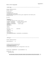
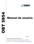
THE MINISTRY of EDUCATION and SCIENCE of RUSSIAN FEDERATION
SAMARA STATE AEROSPACE UNIVERSITY
Working with the Embedded Artists LPC2148
evaluation boards
Learner’s guide
SAMARA
2011
2
Compilers: Kudryavtsev Ilya Alexandrovich,
Kornilin Dmitry Vladimirovich
Working with the Embedded Artists LPC2148 evaluation boards = Работа с
отладочными платами Embedded Artists LPC2148 [Electronic resource] :
Learner’s guide / The Ministry of Education and Science of Russian Federation,
Samara State Aerospace University; compilers I. A. Kudryavtsev, D. V. Kornilin. Electronic text and graphic data (0,56 Mb). - Samara, 2011. - 1 CD-ROM.
Learner’s guide describes the problems of creating and debugging programs in C /
C++ language for NXP ARM7 MCUs and using the evaluation boards LPC2148
Education Boards. Learner’s guide is developed in the Interuniversity Space Research Department. The learner’s guide is intended for the students, studying on the
educational program 010900.68 “Applied mathematics and physics”, on the discipline “Radio complexes for flight monitoring and control of the micro/nanosatellites”
in A semester.
© Samara State Aerospace University, 2011
3
CONTENTS
INTRODUCTION……………………………………………………………….4
1 OVERVIEW OF THE DEBUG BOARD.............................................................................4
2 COMPILE AND DEBUG PROGRAMS USING DEBUGGING TOOLS.............................5
2.1 Compiling the project..................................................................................................................................................5
2.2 Hardware debugging....................................................................................................................................................5
3 INVESTIGATION OF MCU’S FEATURES.........................................................................6
3.1 Basic I/O functions.......................................................................................................................................................6
3.2 MAM module ..............................................................................................................................................................6
3.3 PLL module.................................................................................................................................................................6
3.4 Interrupt system .........................................................................................................................................................6
3.5 SPI module...................................................................................................................................................................7
3.6 ADC operation.............................................................................................................................................................7
4 TASKS FOR YOUR OWN WORK......................................................................................7
5 BIBLIOGRAPHY.................................................................................................................9
INTRODUCTION
During the development of devices based on microcontrollers, there are two interdependent objectives - the development of hardware and software creation. In the
process of development may change the program, and circuit devices, which presents
certain difficulties, and requires significant time and cost. In order to facilitate the development of widely used ready evaluation boards, which set a microcontroller and a
set of standard peripherals. In this paper described the development board LPC2148
Education Boards (from Embedded Artists).
LPC2148 microcontrollers are 32 - bit RISC core with ARM7TDMI-S, has 512
KB of FLASH-memory, 32KB SRAM, as well as a rich set of peripherals. Microcontrollers are equipped with in-circuit programming system based on the JTAG interface and a special boot loader that allows to download the program via UART. Development tools include support for the C/C++, use of which is considered in these
guidelines.
Methodical instructions allow students to learn the basics of debugging boards
to develop and debug programs microcontroller core ARM. Guidance does not describe the features of the core ARM7TDMI, LPC2148 microcontrollers NXP company or a development environment IAR Embedded Workbench, provides only brief
comments, necessary to understand the above code snippet, the appendix contains
fragments of circuit debug board, a list of jobs for own work and sample programs.
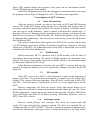
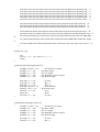
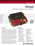
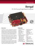
1 Overview of the debug board
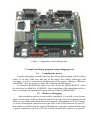
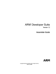
Evaluation Boards such as LPC2148 Education Boards (firm Embedded
Artists), have in their composition, apart from a microcontroller, LCD display, buttons, joystick, serial adapter, speaker, stepper motor, LED matrix interface SPI, temperature sensor and potentiometer for working with ADC module, jack FLASH - card
module and ZigBee. Also on the board (Figure 1) has all the necessary piping microcontroller (system power and clock) and connectors for interface with a computer and
external breadboard.
Figure 1 - Appearance of the debug board
2 Compile and debug programs using debugging tools
2.1
Compiling the project
Consider debugging created in the first part of the draft program with the debug
board. To do this, make sure that part of the project files added «Main.cpp» and
«lcd.cpp», as well as customized configuration of the project «Debug», «Release»
and «RAM». Now the project is ready for compiling and debugging.
To assemble and build the object files you can use the menu PROJECT, select
the tab where the MAKE or COMPILE. After completion of the compilation with errors or warnings will automatically open with the results of MESSAGES.
2.2
Hardware debugging
After simulation process is successfully completed, it is useful to test the program with the help of the development board. This step of the development process
allows to test software/hardware interaction. Attach J-Link module to JTAG connector on the development board and insert the cable to the USB connector on your PC,
then connect carefully with the cable USB minijack on the development board (close
to power connector to the left of JTAG) with the second USB connector on your PC.
Power LED should confirm the presence of the power on the development board.
Check LED blinking on J-Link module.
Set RAM configuration and start the debugger as mentioned earlier then start
the program with the help of «Debug/Go» or F5. Check the project operation.
3 Investigation of MCU’s features
3.1
Basic I/O functions
After the project is started, you can see the words on LCD and LED blinking
below LCD. Using LCD means setting options of its controller and storing codes of
necessary symbols in appropriate location. The details of display’s controller operation you can see in the datasheet, which is placed in Samples\Doc subdirectory. C
language offers set of functions for the operation with text strings, prototypes of such
functions are described in STDIO.H header file. Detailed description you can find in
the Samples\Doc subdirectory. You can also use built-in help system of IAR Embedded Workbench IDE.
This project demonstrates basic options of LPC2148 I/O system with the help
of LED blinking and button polling. Development board has signatures, showing
which pins of the MCU are connected to the certain LED or button and you can find
schematic file in the Doc subdirectory.
3.2
MAM module
MAM accelerates MCU’s operation with FLASH memory with the help of
preliminary instruction fetching. The details of MAM operation are described in the
manual. The project demonstrates operation of MAM, which is activated/deactivated
by the button, connected to P0.14 pin.
Select Release configuration, load the code into MCU’s memory and start the
program. Pressing the button you can see performance changes, caused by the MAM
operation.
3.3
PLL module
When PLL is not active, MCU’s clock frequency is equal to the frequency of
quartz-crystal unit. To use maximum performance, you need to set and activate PLL
module. This requires following procedure: Store M and P coefficients in PLLCFG,
start PLL, wait until capture is performed, set PLL as a clock signal source for the
MCU.
Remove «main.cpp» file from the project (click right mouse button on its
name, then select «Remove» from context menu) and add «main_pll.cpp» file. Select
RAM configuration, compile the project and start the program. Compare LED blinking period before and after Р0.14 button pressing. Determine frequency value of
MCU, when PLL is active.
3.4
Interrupt system
Remove «main_pll.cpp» and «lcd.cpp» files from the project and add
«main_VIC.cpp» and «lpc2xxx_startup.s» instead. The latter is a standard file, including start code of LPC2148 MCU. This file is written in assembler language and is
used for the initializing of interrupt vectors. Usually developers use the copy of this
file with necessary modifications. File «main_VIC.cpp» describes interrupt handlers
for IRQ and FIQ interrupts. IRQ will be attached to timer 0, and FIQ will be attached
to the external interrupt, activating by P0.14 button press. Details of VIC and timer
operation are described in MCU datasheet, placed in the same directory.
Set RAM configuration, build and start program, then open message window
«View\Terminal I/O». Look at the output messages, initiated by IRQ handler.
Press the button (P0.14) and look at the result in the terminal window.
Remove from the project file «main_VIC.cpp» and add file
«main_VIC_UART.cpp». Carefully put the cable from USB jack to UART connector
on the left. Set RAM configuration, build and start program. Start program RS-232,
that is intended for RS-232 information interchange, set there baudrate 19200 and select appropriate СОМ port, set checkbox ASCII. Look at the information, transmitted
by development board to the PC in the main window of the program. Change
baudrate to 9600 and check the operability.
3.5
SPI module
Remove files «main_VIC.cpp» and «lpc2xxx_startup.s», and add files
«main_SPI.cpp», «spi.cpp». Also copy file «spi.h» into the project directory. Set
RAM configuration, build and start program. Using joystick (in the right lower corner
of the development board) change position of active LED in the matrix. Correct the
program to provide diagonal movement. Create your own effect of «LED
movement». Schematic diagram of joystick connections is shown in the appendix.
3.6
ADC operation
Remove files «main_SPI.cpp», «spi.cpp», «spi.h» and add files «main_ADC.cpp», «adc.cpp», , «lcd.cpp». Also copy file «main_ADC.h». Instead
«lpc2xxx_startup.s» insert file «lpc2xxx_startup_no_fiq.s», where fiq_handler is
blocked. This allows to disable FIQ interrupt.
Set RAM configuration, build and start program. Using AIN1 potentiometer
adjust motor rotation rate, simultaneously looking at the LCD. Try to determine rotation rate, analyzing the program and derive formula, connecting the number on LCD
with actual rotation rate. Make the program to display rotational velocity.
4 Tasks for your own work
The complexity of tasks marked with asterisks.
1. Using existing on-board speaker and DAC module of the microcontroller, create audio-frequency generator with a frequency change of command, the computer is
received via the UART (*).
2. Using existing on-board speaker and DAC module of the microcontroller, create audio-frequency oscillator with frequency-controlled potentiometer AIN2. (**)
3. Create a program that writes the data block of 100 bytes in the external EEPROM via I2C (**).
4. Create a program that depicts a snake crawling on dot-matrix display (in the
direction of their choice, the length of 6 pixels). (***)
5. Create a program that displays the current temperature (using a sensor on the
board) on the LCD display (*).
6. Create a program counter pressing P0.14 displaying decimal result on the
LCD. To provide for counter reset (*)
7. Create a program unit that displays the decimal equivalent of the number received by the RS-232 dot matrix display. (**)
8. Create a program of random numbers in the range 0-99 to display on the LCD
display in decimal format by pressing the P0.14. (**)
9. Create a program of light effects on matrix display that changes at random position of luminous points. (***)
10. Create a program for a device that displays on the LCD display the contents
of the counter milliseconds when you click P0.14. (*)
5 Bibliography
1.
Trevor Martin The insider’s guide to the Philips ARM7 – BASED
MICROCONTROLLERS. An engineer’s introduction to the LPC 2000
Series.
2.
UM10139 Volume 1: LPC214X User Manual Rev.01 – 15 August
2005.
3.
ARM7 TDMI Rev.3 Technical Reference Manual
Appendix A
Source code of programs
«main.cpp» -----------------------------------------------------------------------------#include <NXP/iolpc2148.h>
#include <stdio.h>
int main(void);
void InitLCD(void);
void SetBacklight (int Backlight);
void LCDTextOut (unsigned char const* top_line, unsigned char const* bottom_line);
int Sleep (int _slp);
int main()
{
InitLCD ();
SetBacklight (1);
LCDTextOut ("NXP LPC2148", "Basic project");
IO0DIR |= 0x0000FF00;
// Set P0.8 - P0.15 as outputs
IO0SET |= 0x0000FF00;
// Clear P0.8 - P0.15
IO0DIR &= 0xFFFFBFFF;
// P0.14 - input
MAMCR=0;
MAMTIM=3;
int i=8;
while(1)
{
IO0CLR |=(1<<i);
// shift LEDs
Sleep(200);
IO0SET |=(1<<i);
Sleep(200);
if(++i==14) i=8;
if((IO0PIN&0x00004000)==0) MAMCR=2; else MAMCR=0;
}
}
«lcd.cpp» -----------------------------------------------------------------------------#include <NXP\iolpc2148.h>
#define bDISPLAY
16
void SetCommLCD(unsigned char bT);
void SetDataLCD(unsigned char bT);
void WaitReadyLCD(void);
void ShowMsgLCD(unsigned char bT, unsigned char const *szT);
unsigned char szHi[bDISPLAY + 8],szLo[bDISPLAY + 8];
unsigned char const
Symbols[0x100] =
{
0x20,0x00,0x01,0x02,0x03,0x04,0x05,0x06,0x07,0x20,0x20,0x20,0x20,0x20,0x20,0x20, // 0
0x20,0x20,0x20,0x20,0x20,0x20,0x20,0x20,0x20,0x20,0x20,0x20,0x20,0x20,0x20,0x20, // 1
0x20,0x21,0x22,0x23,0x24,0x25,0x26,0x27,0x28,0x29,0x2A,0x2B,0x2C,0x2D,0x2E,0x2F,
0x30,0x31,0x32,0x33,0x34,0x35,0x36,0x37,0x38,0x39,0x3A,0x3B,0x3C,0x3D,0x3E,0x3F,
0x40,0x41,0x42,0x43,0x44,0x45,0x46,0x47,0x48,0x49,0x4A,0x4B,0x4C,0x4D,0x4E,0x4F,
0x50,0x51,0x52,0x53,0x54,0x55,0x56,0x57,0x58,0x59,0x5A,0x5B,0x5C,0x5D,0x5E,0x5F,
0x60,0x61,0x62,0x63,0x64,0x65,0x66,0x67,0x68,0x69,0x6A,0x6B,0x6C,0x6D,0x6E,0x6F,
0x70,0x71,0x72,0x73,0x74,0x75,0x76,0x77,0x78,0x79,0x7A,0x7B,0x7C,0x7D,0xC5,0x01,
// 2
// 3
// 4
// 5
// 6
// 7
0x20,0x20,0x20,0x20,0x20,0x20,0x20,0x20,0x20,0x20,0x20,0x20,0x20,0x20,0x20,0x20, // 8
0x20,0x20,0x20,0x20,0x20,0x20,0x20,0x20,0x20,0x20,0x20,0x20,0x20,0x20,0x20,0x20, // 9
0x20,0x20,0x20,0x20,0x20,0x20,0x20,0x20,0x20,0x20,0x20,0x20,0x20,0x20,0x20,0x20, // A
0xA2,0xB5,0x20,0x20,0x20,0x20,0x20,0x02,0x20,0x20,0x20,0x20,0x20,0x20,0x20,0x20, // B
0x41,0xA0,0x42,0xA1,0xE0,0x45,0xA3,0xA4,0xA5,0xA6,0x4B,0xA7,0x4D,0x48,0x4F,0xA8, // C
0x50,0x43,0x54,0xA9,0xAA,0x58,0xE1,0xAB,0xAC,0xE2,0xAD,0xAE,0xC4,0xAF,0xB0,0xB1, //
D
0x61,0xB2,0xB3,0xB4,0xE3,0x65,0xB6,0xB7,0xB8,0xB9,0xBA,0xBB,0xBC,0xBD,0x6F,0xBE, //
E
0x70,0x63,0xBF,0x79,0xE4,0x78,0xE5,0xC0,0xC1,0xE6,0xC2,0xC3,0xC4,0xC5,0xC6,0xC7 // F
};
int Sleep (int _slp)
{
int j;
for (int i = 0; i < _slp * 1000; i++) j = i + 1;
return j;
}
void SetCommLCD(unsigned char
{
IO1DIR |= (0xFF << 16);
IO1DIR |= (1 << 24);
IO1DIR |= (1 << 25);
IO0DIR |= (1 << 30);
IO0DIR |= (1 << 22);
bT)
// Set data bus as outputs
// Set RS as output
// Set E as output
// Set Backlight control as output
// Set R/W as output
IO1CLR = (1 << 25);
// E down
IO1CLR = (1 << 24);
// RS = 0
IO0CLR = (1 << 22);
// RW = 0
IO1CLR = (0xFF) << 16;
// Clear data bus
IO1SET = (bT) << 16;
// Write data to bus
IO1SET = (1 << 25);
// E up
Sleep (10);
// Wait
IO1CLR = (1 << 25);
// E down
}
void SetDataLCD(unsigned char bT)
{
IO1DIR |= (0xFF << 16);
// Set data bus as outputs
IO1DIR |= (1 << 24);
// Set RS as output
IO1DIR |= (1 << 25);
// Set E as output
IO0DIR |= (1 << 30);
// Set Backlight control as output
IO0DIR |= (1 << 22);
// Set R/W as output
IO1CLR = (1 << 25);
IO1SET = (1 << 24);
// E down
// RS = 1
IO0CLR = (1 << 22);
// RW = 0
IO1CLR = (0xFF) << 16;
// Clear data bus
IO1SET = (bT) << 16;
// Write data to bus
IO1SET = (1 << 25);
// E up
Sleep (10);
// Wait
IO1CLR = (1 << 25);
// E down
}
void WaitReadyLCD(void)
{
Sleep(1);
}
void ShowMsgLCD(unsigned char bT, unsigned char const *szT)
{
WaitReadyLCD();
SetCommLCD(bT);
for (int i = 0; i < bDISPLAY; i++)
{
if ( !*szT ) break;
WaitReadyLCD();
SetDataLCD( Symbols[*szT++]);
}
}
void InitLCD(void)
{
Sleep (20); SetCommLCD(0x30);
Sleep (20); SetCommLCD(0x30);
Sleep (20); SetCommLCD(0x30);
WaitReadyLCD();
WaitReadyLCD();
WaitReadyLCD();
WaitReadyLCD();
WaitReadyLCD();
WaitReadyLCD();
WaitReadyLCD();
SetCommLCD(0x38);
SetCommLCD(0x08);
SetCommLCD(0x01);
SetCommLCD(0x06);
SetCommLCD(0x0C);
SetCommLCD(0x40);
SetCommLCD(0xC4);
}
void LCDTextOut (unsigned char const* top_line, unsigned char const* bottom_line)
{
ShowMsgLCD(0x80, top_line);
ShowMsgLCD(0xC0, bottom_line);
WaitReadyLCD();
SetCommLCD(0xC4);
}
void SetBacklight (int Backlight)
{
if (Backlight) IO0SET |= 1 << 30;
else
IO0CLR |= 1 << 30;
}
«main_pll.cpp» ----------------------------------------------------------------------------
#include <NXP/iolpc2148.h>
#include <stdio.h>
int main(void);
void InitLCD(void);
void SetBacklight (int Backlight);
void LCDTextOut (unsigned char const* top_line, unsigned char const* bottom_line);
int Sleep (int _slp);
int main()
{
int LOW=1;
InitLCD ();
SetBacklight (1);
LCDTextOut ("NXP LPC2148", "Basic project");
IO0DIR |= 0x0000FF00;
// Set P0.8 - P0.15 as outputs
IO0SET |= 0x0000FF00;
// Clear P0.8 - P0.15
IO0DIR &= 0xFFFFBFFF;
// P0.14 - input
int i=8;
while(1)
{
IO0CLR |=(1<<i);
// shift LEDs
Sleep(200);
IO0SET |=(1<<i);
Sleep(200);
if(++i==14) i=8;
if((IO0PIN&0x00004000)==0)
{
if(LOW==1)
{
PLLCFG = 0x45;
/* M = 5, P = 2 */
PLLCON = 0x01;
/* PLL Enable */
PLLFEED = 0xAA;
/* Feed Sequence 1 */
PLLFEED = 0x55;
/* Feed Sequence 2 */
while ((PLLSTAT & 0x0400) == 0);
/* Wait for PLL Lock */
PLLCON = 0x03;
/* PLL Enable & Connect */
PLLFEED = 0xAA;
/* Feed Sequence 1 */
PLLFEED = 0x55;
/* Feed Sequence 2 */
LOW=0;
}
}
else
{
if (LOW==0)
{
PLLCFG = 0x23;
/* M = 3, P = 1 */
PLLCON = 0x01;
/* PLL Enable */
PLLFEED = 0xAA;
/* Feed Sequence 1 */
PLLFEED = 0x55;
/* Feed Sequence 2 */
while ((PLLSTAT & 0x0400) == 0);
/* Wait for PLL Lock */
PLLCON = 0x03;
/* PLL Enable & Connect */
PLLFEED = 0xAA;
/* Feed Sequence 1 */
PLLFEED = 0x55;
/* Feed Sequence 2 */
LOW=1;
}
}
}
}
«main_VIC.cpp» -------------------------------------------------------------------------#include <NXP/iolpc2148.h>
#include <stdio.h>
#include <intrinsics.h>
#define XTALFREQ 12000000
//XTAL frequency in Hz
#define PCLKFREQ (XTALFREQ/4) //pclk must always be XTALFREQ/4?
#define TICKS_PER_SECOND 20
// TIMER0 interrupt is 100Hz
#define FALSE 0
#define TRUE !(FALSE)
int main(void);
void InitLCD(void);
void SetBacklight (int Backlight);
int Sleep (int _slp);
void LCDTextOut (unsigned char const* top_line, unsigned char const* bottom_line);
extern "C" __fiq __arm void fiq_handler (void);
__irq __arm void MM_TIMER0_ISR();
unsigned int Int_Count;
unsigned char buffer[16];
bool bl_TimerFlag;
int main(void)
{
Int_Count=0;
InitLCD();
SetBacklight (1);
bl_TimerFlag = FALSE;
VPBDIV_bit.VPBDIV = 0;
// Init Peripherial divider Pckl = Clk/4
T0IR=0xFF;
// reset match and capture event interrupts
T0TC=0;
// Clear timer counter
T0PR= 0;
// No Prescalar
T0MR0=PCLKFREQ/100;
// Count up to 36,864 for 100Hz interrupt, period = 10ms
T0MCR = 3;
// Reset Timer Counter & Interrupt on match
T0TCR = 1;
// Counting enable
//initialize P0.14 to EINT1 (active falling edge)
EXTMODE = 0x00000002;
//EINT1 is edge sensitive
EXTPOLAR = 0x00000000;
//EINT1 is falling edge sensitive
PINSEL0 &= ~0x30000000;
PINSEL0 |= 0x20000000;
EXTINT = 0x00000002;
//reset EINT1 IRQ flag
VICIntSelect = 0;
// Set all VIC interrupts to IRQ for now
VICIntEnClear = 0xFFFFFFFF; // Diasable all interrupts
VICProtection = 0;
// VIC registers can be accessed in User or
// privileged mode
VICVectAddr = 0;
// Clear interrupt
VICProtection = 0;
// Accesss VIC in USR | PROTECT
VICIntSelect |= 0x00008000;
//EINT1 interrupt is assigned to FIQ (not IRQ)
VICIntSelect &= ~(1<<VIC_TIMER0);
// Timer 0 intrpt is an IRQ (VIC_TIMER0 = 4)
VICVectAddr0 = (unsigned int)&MM_TIMER0_ISR; // Install ISR in VIC addr slot 0
VICVectCntl0 = 0x20 | VIC_TIMER0;
// IRQ type, TIMER 0 int enabled
VICIntEnable = 0x00008000;
//enable eint1 interrupt
VICIntEnable |= (1<<VIC_TIMER0);
// enable Timer0 Interrupt
__enable_interrupt();
// Global interrupt enable
while(TRUE)
// Foreground "task"
{
if(bl_TimerFlag)
{
bl_TimerFlag = FALSE;
// Clear this flag if set by MM_TIMER0_ISR
printf("IRQ interrupt!\n");
sprintf((char*)buffer,"Interrupt %d",Int_Count++);
LCDTextOut("IRQ TEST",buffer);
}
}
}
// end foreground loop
// end main()
/*************************************************************************
* Function Name: fiq_handler
* Parameters: void
* Return: void
*
* Description: FIQ subroutine
* Note: This is ARM mode code - full 32 bit code
*************************************************************************/
extern "C"__fiq __arm void fiq_handler (void)
{
printf("FIQ interrupt!\n");
EXTINT = 0x00000002;
//reset IRQ flag
VICVectAddr = 0x00;
//dummy write to VIC to signal end of interrupt
}
__irq __arm void MM_TIMER0_ISR()
{
static unsigned int us_Ticks=0;
us_Ticks++;
if(us_Ticks == TICKS_PER_SECOND)
{
bl_TimerFlag = TRUE;
// The background "task"
us_Ticks = 0;
}
T0IR = 1;
// Clear timer interrupt
VICVectAddr = 0;
}
«lpc2xxx_startup.s»----------------------------------------------------------------------;;;;;;;;;;;;;;;;;;;;;;;;;;;;;;;;;;;;;;;;;;;;;;;;;;;;
;;
;; Part one of the system initialization code,
;; contains low-level
;; initialization.
;;
;; Copyright 2006 IAR Systems. All rights reserved.
;;
;; $Revision: 30870 $
;;
MODULE ?cstartup
;; Forward declaration of sections.
SECTION IRQ_STACK:DATA:NOROOT(3)
;; SECTION FIQ_STACK:DATA:NOROOT(3)
SECTION ABT_STACK:DATA:NOROOT(3)
SECTION SVC_STACK:DATA:NOROOT(3)
SECTION UND_STACK:DATA:NOROOT(3)
SECTION CSTACK:DATA:NOROOT(3)
;
; The module in this file are included in the libraries, and may be
; replaced by any user-defined modules that define the PUBLIC symbol
; __iar_program_start or a user defined start symbol.
;
; To override the cstartup defined in the library, simply add your
; modified version to the workbench project.
SECTION .intvec:CODE:NOROOT(2)
PUBLIC __vector
PUBLIC __vector_0x14
PUBLIC __iar_program_start
EXTERN irq_handler ;;,fiq_handler
ARM
__vector:
;;
ldr pc,[pc,#+24]
B .
B .
B .
B .
__vector_0x14:
DC32 0
ldr pc,[pc,#+24]
ldr pc,[pc,#+24]
;; Reset
;; Undefined instructions
;; Software interrupt (SWI/SVC)
;; Prefetch abort
;; Data abort
;; RESERVED
;; IRQ
;; FIQ
DC32 __iar_program_start
;; Reset
DC32 0
;; Undefined instructions
DC32 0
;; Software interrupt (SWI/SVC)
DC32 0
;; Prefetch abort
DC32 0
;; Data abort
DC32 0
;; RESERVED
DC32 irq_handler
;; IRQ
;; DC32 fiq_handler
;; FIQ
; -------------------------------------------------; ?cstartup -- low-level system initialization code.
;
; After a reser execution starts here, the mode is ARM, supervisor
; with interrupts disabled.
;
SECTION .text:CODE:NOROOT(2)
;
PUBLIC ?cstartup
EXTERN ?main
REQUIRE __vector
ARM
__iar_program_start:
?cstartup:
;
; Add initialization needed before setup of stackpointers here.
;
; LPC2148 Errata
; Date: August 5, 2005
; Document Release: Version 1.0
; Device Affected: LPC2148
; Incorrect read of data from SRAM after Reset and MAM is not enabled or partially enabled MAM.1
; Init MAM before acsses to SRAM
MAMCR DEFINE 0xE01FC000
; MAM Control Register
MAMTIM DEFINE 0xE01FC004 ; MAM Timing register
ldr
ldr
ldr
str
ldr
str
ldr
str
r0,=MAMCR
r1,=MAMTIM
r2,=0
r2,[r0]
r2,=7
r2,[r1]
r2,=2
r2,[r0]
;
; Initialize the stack pointers.
; The pattern below can be used for any of the exception stacks:
; FIQ, IRQ, SVC, ABT, UND, SYS.
; The USR mode uses the same stack as SYS.
; The stack segments must be defined in the linker command file,
; and be declared above.
;
; -------------------; Mode, correspords to bits 0-5 in CPSR
MODE_MSK DEFINE 0x1F
USR_MODE DEFINE 0x10
;;FIQ_MODE DEFINE 0x11
IRQ_MODE DEFINE 0x12
SVC_MODE DEFINE 0x13
ABT_MODE DEFINE 0x17
UND_MODE DEFINE 0x1B
SYS_MODE DEFINE 0x1F
; Bit mask for mode bits in CPSR
; User mode
; Fast Interrupt Request mode
; Interrupt Request mode
; Supervisor mode
; Abort mode
; Undefined Instruction mode
; System mode
mrs r0,cpsr
; Original PSR value
bic r0,r0,#MODE_MSK
; Clear the mode bits
orr r0,r0,#SVC_MODE
; Set Supervisor mode bits
msr cpsr_c,r0
; Change the mode
ldr sp,=SFE(SVC_STACK)
; End of SVC_STACK
bic r0,r0,#MODE_MSK
; Clear the mode bits
orr r0,r0,#ABT_MODE
; Set Abort mode bits
msr cpsr_c,r0
; Change the mode
ldr sp,=SFE(ABT_STACK)
; End of ABT_STACK
bic r0,r0,#MODE_MSK
; Clear the mode bits
orr r0,r0,#UND_MODE
; Set Undefined mode bits
msr cpsr_c,r0
; Change the mode
ldr sp,=SFE(UND_STACK)
; End of UND_STACK
;
;
;
;
bic r0,r0,#MODE_MSK
orr r0,r0,#FIQ_MODE
msr cpsr_c,r0
ldr sp,=SFE(FIQ_STACK)
; Clear the mode bits
; Set FIR mode bits
; Change the mode
; End of FIR_STACK
bic r0,r0,#MODE_MSK
orr r0,r0,#IRQ_MODE
msr cpsr_c,r0
ldr sp,=SFE(IRQ_STACK)
; Clear the mode bits
; Set IRQ mode bits
; Change the mode
; End of IRQ_STACK
bic r0,r0,#MODE_MSK
orr r0,r0,#SYS_MODE
msr cpsr_c,r0
ldr sp,=SFE(CSTACK)
; Clear the mode bits
; Set System mode bits
; Change the mode
; End of CSTACK
#ifdef __ARMVFP__
; Enable the VFP coprocessor.
mov r0, #0x40000000
fmxr fpexc, r0
; Set EN bit in VFP
; FPEXC, clear others.
; Disable underflow exceptions by setting flush to zero mode.
; For full IEEE 754 underflow compliance this code should be removed
; and the appropriate exception handler installed.
mov r0, #0x01000000
; Set FZ bit in VFP
fmxr fpscr, r0
; FPSCR, clear others.
#endif
; Add more initialization here
; Continue to ?main for more IAR specific system startup
ldr
bx
r0,=?main
r0
END
«main_VIC_UART.cpp»----------------------------------------------------------------/******************************************************************************
Minimal code for setting up Timer0 to interrupt on compare match on channel 0
to interrupt at 100Hz
XTALFREQ 12000000
//XTAL frequency in Hz
PCLKFREQ (XTALFREQ/4) //pclk must always be XTALFREQ/4?
Open terminal I/O window in debugger using View/Terminal I/O in C-SPY to see
VICVectAddr value in exception handler. This is not routed to the serial port
because UARTx is not configured and no implementation of putchar()
******************************************************************************/
#include <NXP/iolpc2148.h>
#include <stdio.h>
#include <intrinsics.h>
#define TICKS_PER_SECOND 100 // TIMER0 interrupt is 100Hz
#define XTALFREQ 12000000
//XTAL frequency in Hz
#define PCLKFREQ (XTALFREQ/4) //pclk must always be XTALFREQ/4
#define FALSE 0
#define TRUE !(FALSE)
int main(void);
extern "C" __fiq __arm void fiq_handler (void);
extern "C" __irq __arm void irq_handler (void);
void TransmitString(char* pStr);
bool bl_TimerFlag;
int main(void)
{
bl_TimerFlag = FALSE;
VPBDIV_bit.VPBDIV = 0;
U0FCR=0x07;
U0LCR = 0x83;
U0DLL = 0x0A;
U0DLM = 0;
U0LCR &=0x7F;
// Init Peripherial divider Pckl = Clk/4
//Configure UART0 to 19200 baud, 8 bit, 1 stop, no parity
// Enable FIFOs whether used or not
// U0LCR = 0X80-enable access to divisor
// latch bit, necessary for setting baud rate
// Eight bits
// No parity
// One stop bit
// Disable access to divisor latch
PINSEL0 = 0x05;
T0IR=0xFF;
// reset match and capture event interrupts
T0TC=0;
// Clear timer counter
T0PR= 0;
// No Prescalar
T0MR0=PCLKFREQ/100;
// Count up to 36,864 for 100Hz interrupt, period = 10ms
T0MCR = 3;
// Reset Timer Counter & Interrupt on match
T0TCR = 1;
// Counting enable
//initialize P0.14 to EINT1 (active falling edge)
EXTMODE = 0x00000002;
//EINT1 is edge sensitive
EXTPOLAR = 0x00000000;
//EINT1 is falling edge sensitive
PINSEL0 &= ~0x30000000;
PINSEL0 |= 0x20000000;
EXTINT = 0x00000002;
//reset EINT1 IRQ flag
VICIntSelect = 0;
// Set all VIC interrupts to IRQ for now
VICIntEnClear = 0xFFFFFFFF; // Diasable all interrupts
VICProtection = 0;
// VIC registers can be accessed in User or
// privileged mode
VICVectAddr = 0;
// Clear interrupt
VICProtection = 0;
// Accesss VIC in USR | PROTECT
VICIntSelect |= 0x00008000;
//EINT1 interrupt is assigned to FIQ (not IRQ)
VICIntSelect &= ~(1<<VIC_TIMER0);
// Timer 0 intrpt is an IRQ (VIC_TIMER0 = 4)
VICVectAddr0 = (unsigned int)&irq_handler; // Install ISR in VIC addr slot 0
VICVectCntl0 = 0x20 | VIC_TIMER0;
// IRQ type, TIMER 0 int enabled
VICIntEnable = 0x00008000;
//enable eint1 interrupt
VICIntEnable |= (1<<VIC_TIMER0);
// enable Timer0 Interrupt
__enable_interrupt();
// Global interrupt enable
while(TRUE)
// Foreground "task"
{
if(bl_TimerFlag)
{
bl_TimerFlag = FALSE;
TransmitString("IRQ Interrupt processed");
}
}
// end foreground loop
}
// end main()
/******************************************************************************
* Function Name: irq_handler
* Parameters: void
* Return: void
*
* Description: IRQ exception handler, this will call appropriate isr after
* reading value out of VICVectAddr
* Note: This is ARM mode code - full 32 bit code
*****************************************************************************/
extern "C" __irq __arm void irq_handler (void)
{
static unsigned int us_count=0;
//us_count++;
if(us_count++ == TICKS_PER_SECOND)
{
us_count = 0;
bl_TimerFlag = TRUE;
}
VICVectAddr = 0;
// Clear interrupt in VIC
T0IR = 1;
}
/*************************************************************************
* Function Name: fiq_handler
* Parameters: void
* Return: void
*
* Description: FIQ subroutine
* Note: This is ARM mode code - full 32 bit code
*************************************************************************/
extern "C"__fiq __arm void fiq_handler (void)
{
TransmitString("FIQ interrupt!");
EXTINT = 0x00000002;
VICVectAddr = 0x00;
//dummy write to VIC to signal end of interrupt
}
void TransmitString(char* pStr)
{
while (*pStr != 0)
{
U0THR = *pStr;
while(!(U0LSR & 0x40));
pStr++;
}
}
«main_SPI.cpp»----------------------------------------------------------------#include <NXP/iolpc2148.h>
#include "spi.h"
int main(void);
int Sleep (int _slp);
int main (void)
{
int X = 4, Y = 4;
InitSPI ();
while (1)
{
switch ((IO0PIN & (0x1F << 16)) >> 16)
// Read value from joystick
{
case 0x1D: if (Y < 8) Y++; break; // Up
case 0x0F: if (Y > 1) Y--; break; // Down
case 0x17: if (X > 1) X--; break; // Left
case 0x1B:
if (X < 8) X++; break; // Right
case (0x1D&0x17): if ((Y < 8)&(X > 1)){ Y++; X--;} break; // UpLeft
case (0x1D&0x1B): if ((Y < 8)&(X < 8)){ Y++; X++;} break;
// UpRight
case (0x0F&0x17): if ((Y > 1)&(X > 1)){ Y--; X--;} break; //DownLeft
case (0x0F&0x1B): if ((Y > 1)&(X < 8)){ Y--; X++;} break; // DownRight
default: break;
}
SPIPutDot (X, Y);
Sleep (300);
}
}
int Sleep (int _slp)
{
int j;
for (int i = 0; i < _slp * 1000; i++) j = i + 1;
return j;
}
«spi.cpp»------------------------------------------------------------------------------#include <NXP/iolpc2148.h>
#include "spi.h"
void InitSPI (void)
{
IO0DIR |= (1 << 15);
// Chip select for shift registers
IO0SET = (1 << 15);
PINSEL0 |= (1 << 8) | (1 << 10) | (1 << 12);
S0SPCR =
(0 << 2) |
// set up bits per transfer (0 - 8bit, 1 - defined)
(1 << 3) |
// CPHA mode
(1 << 4) |
// SCK is active high
(1 << 5) |
// Set SPI as master
(0 << 8);
// 16 bits per transfer
S0SPCCR = 64;
}
void SPIPutDot (int x, int y)
{
IO0SET = (1 << 15);
S0SPDR = ~(1 << (y - 1));
while ((S0SPSR & (1 << 7)) == 0);
S0SPDR = ~(1 << (8 - x));
while ((S0SPSR & (1 << 7)) == 0);
IO0CLR = (1 << 15);
}
// Pull up P0.15
// Wait until data is sent
// Wait until data is sent
// Pull down P0.15 ("apply new settings")
«spi.h»----------------------------------------------------------------#ifndef SPI_H
#define SPI_H
void InitSPI (void);
void SPIPutDot (int x, int y);
#endif
«main_ADC.cpp»----------------------------------------------------------------/******************************************************************************
Minimal code for setting up Timer0 to interrupt on compare match on channel 0
to interrupt at 100Hz
XTALFREQ 12000000
//XTAL frequency in Hz
PCLKFREQ (XTALFREQ/4) //pclk must always be XTALFREQ/4?
Open terminal I/O window in debugger using View/Terminal I/O in C-SPY to see
VICVectAddr value in exception handler. This is not routed to the serial port
because UARTx is not configured and no implementation of putchar()
******************************************************************************/
#include <NXP/iolpc2148.h>
#include <stdio.h>
#include <intrinsics.h>
#include "main_ADC.h"
unsigned int Speed;
int main(void)
{
unsigned char buffer[32];
VPBDIV_bit.VPBDIV = 0;
T0IR=0xFF;
T0TC=0;
T0PR= 0;
T0MR0=1000;
T0MCR = 3;
T0TCR = 1;
// Init Peripherial divider Pclk = Clk/4
// reset match and capture event interrupts
// Clear timer counter
// No Prescaler
// Count up to 36,864 for 1000Hz interrupt, period = 1ms
// Reset Timer Counter & Interrupt on match
// Counting enable
VICIntSelect = 0;
// Set all VIC interrupts to IRQ for now
VICIntEnClear = 0xFFFFFFFF; // Diasable all interrupts
VICProtection = 0;
// VIC registers can be accessed in User or
// privileged mode
VICVectAddr = 0;
// Clear interrupt
VICProtection = 0;
// Accesss VIC in USR | PROTECT
VICIntSelect &= ~(1<<VIC_TIMER0);
// Timer 0 intrpt is an IRQ (VIC_TIMER0 = 4)
VICVectAddr0 = (unsigned int)&irq_handler; // Install ISR in VIC addr slot 0
VICVectCntl0 = 0x20 | VIC_TIMER0;
// IRQ type, TIMER 0 int enabled
VICIntEnable |= (1<<VIC_TIMER0);
// enable Timer0 Interrupt
InitADC();
InitLCD ();
SetBacklight (1);
LCDTextOut ("NXP LPC2148", "ADC project");
IO0DIR |= 0x0020FF00;
// Set P0.8 - P0.15,P0.21 as outputs
IO0SET |= 0x0020FF00;
// Clear P0.8 - P0.15,P0.21
__enable_interrupt();
// Global interrupt enable
while(TRUE)
{
Speed=1023-ADCReadValue();
if(Speed<23) Speed=23;
sprintf((char*)buffer,"Speed=%d ",1023-Speed);
LCDTextOut ("NXP LPC2148", buffer);
Sleep(100);
}
}
/******************************************************************************
* Function Name: irq_handler
* Parameters: void
* Return: void
*
* Description: IRQ exception handler, this will call appropriate isr after
* reading value out of VICVectAddr
* Note: This is ARM mode code - full 32 bit code
*****************************************************************************/
extern "C" __irq __arm void irq_handler (void)
{
const int A[12]={1,1,0,0,1,1,0,0,1,1,0,0};
const int B[12]={0,1,1,0,0,1,1,0,0,1,1,0};
static unsigned int us_Ticks,n;
us_Ticks++;
if(us_Ticks >= Speed)
{
us_Ticks = 0;
if(A[n]==0) IO0CLR|=(1<<21); else IO0SET|=(1<<21);
if(B[n]==0) IO0CLR|=(1<<12); else IO0SET|=(1<<12);
if(++n>11) n=0;
}
T0IR = 1;
// Clear timer interrupt
VICVectAddr = 0;
// Clear interrupt in VIC
}
«adc.cpp»----------------------------------------------------------------#include <NXP/iolpc2148.h>
void InitADC (void)
{
/**********************************************************/
/*
Connect PIN connect block to ADC0.1
*/
/**********************************************************/
PINSEL1 |= (1 << 24);
/**********************************************************/
/*
Configure ADC
*/
/**********************************************************/
AD0CR =
(1 << 1) |
// Select ADC0.1 channel is active
(4 << 8) |
// Set Clock divider
(1 << 16) |
// Set BURST
(0 << 17) |
// Set ADC resolution
(1 << 21) |
// Power on ADC
(1 << 24);
// Start conversion now
}
int ADCReadValue (void)
{
int ADCValue;
/**********************************************************/
/*
Read value from ADC
*/
/**********************************************************/
while (((ADCValue = AD0DR) & 0x80000000) == 0);
/**********************************************************/
/*
Separate ADC value from other information
*/
/**********************************************************/
return (ADCValue >> 6) & (0x3FF);
}
«main_ADC.h»----------------------------------------------------------------#define XTALFREQ 12000000
//XTAL frequency in Hz
#define PCLKFREQ (XTALFREQ/4) //pclk must always be XTALFREQ/4?
#define FALSE 0
#define TRUE !(FALSE)
int main(void);
void InitLCD(void);
void SetBacklight (int Backlight);
void LCDTextOut (unsigned char const* top_line, unsigned char const* bottom_line);
int Sleep (int _slp);
void InitADC (void);
int ADCReadValue (void);
extern "C" __irq __arm void irq_handler (void);
«lpc2xxx_startup_no_fiq.s»------------------------------------------------------------;;;;;;;;;;;;;;;;;;;;;;;;;;;;;;;;;;;;;;;;;;;;;;;;;;;;
;;
;; Part one of the system initialization code,
;; contains low-level
;; initialization.
;;
;; Copyright 2006 IAR Systems. All rights reserved.
;;
;; $Revision: 30870 $
;;
MODULE ?cstartup
;; Forward declaration of sections.
SECTION IRQ_STACK:DATA:NOROOT(3)
SECTION FIQ_STACK:DATA:NOROOT(3)
SECTION ABT_STACK:DATA:NOROOT(3)
SECTION SVC_STACK:DATA:NOROOT(3)
SECTION UND_STACK:DATA:NOROOT(3)
SECTION CSTACK:DATA:NOROOT(3)
;
; The module in this file are included in the libraries, and may be
; replaced by any user-defined modules that define the PUBLIC symbol
; __iar_program_start or a user defined start symbol.
;
; To override the cstartup defined in the library, simply add your
; modified version to the workbench project.
SECTION .intvec:CODE:NOROOT(2)
PUBLIC __vector
PUBLIC __vector_0x14
PUBLIC __iar_program_start
EXTERN irq_handler
ARM
__vector:
;;
ldr pc,[pc,#+24]
B .
B .
B .
B .
;; Reset
;; Undefined instructions
;; Software interrupt (SWI/SVC)
;; Prefetch abort
;; Data abort
__vector_0x14:
DC32 0
ldr pc,[pc,#-0xFF0]
DC32 0
DC32
DC32
DC32
DC32
DC32
DC32
DC32
DC32
;; RESERVED
;; IRQ
;; FIQ
__iar_program_start
;; Reset
0
;; Undefined instructions
0
;; Software interrupt (SWI/SVC)
0
;; Prefetch abort
0
;; Data abort
0
;; RESERVED
0
;; IRQ
0
;; FIQ
; -------------------------------------------------; ?cstartup -- low-level system initialization code.
;
; After a reser execution starts here, the mode is ARM, supervisor
; with interrupts disabled.
;
SECTION .text:CODE:NOROOT(2)
;
PUBLIC ?cstartup
EXTERN ?main
REQUIRE __vector
ARM
__iar_program_start:
?cstartup:
;
; Add initialization needed before setup of stackpointers here.
;
; LPC2148 Errata
; Date: August 5, 2005
; Document Release: Version 1.0
; Device Affected: LPC2148
; Incorrect read of data from SRAM after Reset and MAM is not enabled or partially enabled MAM.1
; Init MAM before acsses to SRAM
MAMCR DEFINE 0xE01FC000
; MAM Control Register
MAMTIM DEFINE 0xE01FC004 ; MAM Timing register
ldr
ldr
ldr
str
ldr
str
ldr
str
r0,=MAMCR
r1,=MAMTIM
r2,=0
r2,[r0]
r2,=7
r2,[r1]
r2,=2
r2,[r0]
;
; Initialize the stack pointers.
; The pattern below can be used for any of the exception stacks:
; FIQ, IRQ, SVC, ABT, UND, SYS.
; The USR mode uses the same stack as SYS.
; The stack segments must be defined in the linker command file,
; and be declared above.
;
; -------------------; Mode, correspords to bits 0-5 in CPSR
MODE_MSK DEFINE 0x1F
USR_MODE DEFINE 0x10
FIQ_MODE DEFINE 0x11
IRQ_MODE DEFINE 0x12
SVC_MODE DEFINE 0x13
ABT_MODE DEFINE 0x17
UND_MODE DEFINE 0x1B
SYS_MODE DEFINE 0x1F
; Bit mask for mode bits in CPSR
; User mode
; Fast Interrupt Request mode
; Interrupt Request mode
; Supervisor mode
; Abort mode
; Undefined Instruction mode
; System mode
mrs r0,cpsr
; Original PSR value
bic r0,r0,#MODE_MSK
; Clear the mode bits
orr r0,r0,#SVC_MODE
; Set Supervisor mode bits
msr cpsr_c,r0
; Change the mode
ldr sp,=SFE(SVC_STACK)
; End of SVC_STACK
bic r0,r0,#MODE_MSK
; Clear the mode bits
orr r0,r0,#ABT_MODE
; Set Abort mode bits
msr cpsr_c,r0
; Change the mode
ldr sp,=SFE(ABT_STACK)
; End of ABT_STACK
bic r0,r0,#MODE_MSK
; Clear the mode bits
orr r0,r0,#UND_MODE
; Set Undefined mode bits
msr cpsr_c,r0
; Change the mode
ldr sp,=SFE(UND_STACK)
; End of UND_STACK
bic r0,r0,#MODE_MSK
orr r0,r0,#FIQ_MODE
msr cpsr_c,r0
ldr sp,=SFE(FIQ_STACK)
; Clear the mode bits
; Set FIR mode bits
; Change the mode
; End of FIR_STACK
bic r0,r0,#MODE_MSK
orr r0,r0,#IRQ_MODE
msr cpsr_c,r0
ldr sp,=SFE(IRQ_STACK)
; Clear the mode bits
; Set IRQ mode bits
; Change the mode
; End of IRQ_STACK
bic r0,r0,#MODE_MSK
orr r0,r0,#SYS_MODE
msr cpsr_c,r0
ldr sp,=SFE(CSTACK)
; Clear the mode bits
; Set System mode bits
; Change the mode
; End of CSTACK
#ifdef __ARMVFP__
; Enable the VFP coprocessor.
mov r0, #0x40000000
fmxr fpexc, r0
; Set EN bit in VFP
; FPEXC, clear others.
; Disable underflow exceptions by setting flush to zero mode.
; For full IEEE 754 underflow compliance this code should be removed
; and the appropriate exception handler installed.
mov
fmxr
r0, #0x01000000
fpscr, r0
; Set FZ bit in VFP
; FPSCR, clear others.
#endif
; Add more initialization here
; Continue to ?main for more IAR specific system startup
ldr
bx
END
r0,=?main
r0
Appendix B
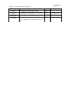
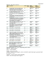
Table B.1 IO ports control registers
Name
IOXPIN
description
Designed to read the state of pin
access
R/W
State after reset
-
IOXSET
Recording 1 set high logic level at pin
R/W
0x00000000
IOXCLR
Recording 1 set low logic level at pin
R/W
0x00000000
IOXDIR
The direction of transmission. Recording 1 configures the output mode to output
R/W
0x00000000
Appendix C
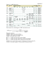
Table C.1 UART0 Registers
The formula for calculating the UART transmission rate
The main registers:
U0RSR - register the received data;
U0THR - data register for transmission;
U0IER - Interrupt Enable UART:
Bit 0 - 1 - enable interrupt if the received data;
Bit 1 - 1 - enable interrupt when buffer under the program;
Bit 2 - 1 - enable interrupt when a particular state line RX
U0LSR - line control status register: Configures the format make [3];
U0LSR - line status register: Current status of the port (error)
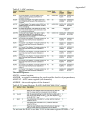
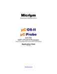
Appendix D
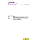
Figure C.1 - Formats the transfer module in SPI
Table D.1 SPI module registers
The most important registers are:
S0SPCR - control register, the format detailed in [3];
S0SPSR - status register reflects the current state (error);
S0SPDR - register containing the transmitted and received data;
S0SPCCR-register control the frequency transmit mode MASTER.
Appendix E
Table E.1 The timer registers
The main registers: (X - 0 or 1, depending on the timer)
ThTCR - control register;
TxTC - count register;
TxPR - register prescaler;
TxMR0 - register containing the value at which the match interrupt is generated and
the counter is reset;
TxMCR - control register mode matching;
TxIR - timer interrupt control register.
Appendix F
Table F.1 ADC registers
The main registers:
ADCR - control register;
ADGDR - a register containing the result and the last bit of preparedness;
ADSTAT - ADC status register (all channels);
ADDRX - the result register of the channel.
Table E.2 Format Registry DACR (0xE006C000) DAC control
To activate the DAC to set bits 19:18 in the state register PINSEL1 "10"
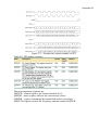
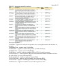
Appendix G
Table G.1 interrupt controller registers
The main registers:
VicSoftInt - register bits which correspond to the existing demand at the moment interrupts;
VicSoftIntClear - register reset VicSoftInt;
VicIntEnable - register an individual permit / prohibit interrupt;
VicIntEnClear - register reset VicIntEnable;
VicIntSelect - register selection anchor (IRQ or FIQ) for each interrupt;
VicVectCntl0-15 - slots Registers IRQ (bit resolution and contain a number of slots
for each of the 16 vector interrupt IRQ);
VicVectAddr0-15 - Address registers vectors IRQ;
VicVectDefAddr - address register handler nevektornogo IRQ;
VicVectAddr - register containing the address of the treated IRQ;
VicProtection - register to enable access to the registers of VIC.
Table G.2 Interrupt Sources
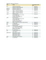
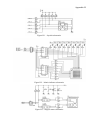
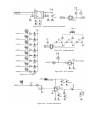
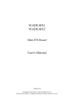
Appendix H
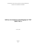
Figure H.1 - Joystick schematics
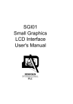
Figure H.2 - Matrix indicator schematics
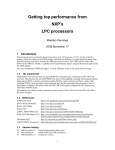
Figure H.3 - Stepper motor schematics
Figure H.4 - Temperature sensor schematics
Figure H.5 - RGB indicator
Figure H.6 - P0.14 button
Figure H.7 - LEDs
Figure H.8 - Speaker schematics
Educational edition
Working with the Embedded Artists LPC2148 evaluation boards
Learner’s guide.
Compilers: Ilya Kudryavtsev, Dmitry Kornilin
Samara State Aerospace University (SSAU)