1
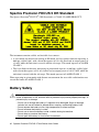
Spectra Precision®
FOCUS ® 5 TOTAL STATION
USER GUIDE
Spectra Precision
FOCUS 5
Total Station
®
®
User Guide
Version 01.00
October 2007
Contact details
Le présent appareil numérique n’émet pas de bruits
radioélectriques dépassant les limites applicables aux
appareils numériques de Classe B prescrites dans le
règlement sur le brouillage radioélectrique édicté par le
Ministère des Communications du Canada.
Spectra Precision
10355 Westmoore Drive
Suite #100
Westminister, CO 80021
U.S.A.
Europe
+1-720-587-4700 Phone
888-477-7516 (Toll Free in U.S.A.)
www.spectraprecision.com
Copyrigt and Trademarks
Copyright © 2007, Spectra Precision. All rights
reserved.
Autolock, FOCUS, Spectra Precision and Tracklight are
trademarks of Spectra Precision, registered in the United
States Patent and Trademark Office and other countries.
Spectra Precision logo is a Trademark of Spectra
Precision.
This product has been tested and found to
comply with the requirements for a Class B
device pursuant to European Council Directive
89/336/EEC on EMC, thereby satisfying the
requirements for CE Marking and sale within the
European Economic Area (EEA). These requirements
are designed to provide reasonable protection against
harmful interference when the equipment is operated in
a residential or commercial environment.
The compliance to the applicable requirements is
detailed in the official Declaration of Conformity
document, which is filed at Spectra Precision.
All other trademarks are the property of their respective
owners.
For product recycling instructions and more information,
please go to www.spectraprecision.com/ev.shtml.
Patents pending.
Recycling in Europe: To recycle Spectra
Precision WEEE (Waste Electrical and
Electronic Equipment, products that run on
electrical power.), Call +31 497 53 24 30, and
ask for the "WEEE Associate". Or, mail a
request for recycling instructions to:
Spectra Precision Europe BV
c/o Menlo Worldwide Logistics
Meerheide 45
5521 DZ Eersel, NL
Release Notice
This is the October 2007 release version 01.00 of the
Spectra Precision FOCUS 5 Total Station user guide. It
applies to the Spectra Precision FOCUS 5 Total Station.
The following limited warranties give you specific legal
rights. You may have others, which vary from
state/jurisdiction to state/jurisdiction.
Product Warranty Information
For applicable product warranty information, please
refer to the Warranty Card included with this Spectra
Precision product, or consult your Spectra Precision
dealer.
Registration
To receive information regarding updates and new
products, please contact your local dealer or visit the
Spectra Precision website at
www.spectraprecision.com/register.
Upon registration you may select the newsletter, upgrade
or new product information you desire.
Notices
Australia and New Zealand
This product conforms with
the regulatory requirements
of the Australian
Communications Authority (ACA) EMC framework,
thus satisfying the requirements for C-Tick Marking and
sale within Australia and New Zealand.
N 1023
Canada
This Class B digital apparatus complies with Canadian
ICES-003
This digital apparatus does not exceed the Class B limits
for radio noise emissions from digital apparatus as set
out in the radio interference regulations of the Canadian
Department of Communications.
USA
Class B Statement – Notice to Users. This equipment
has been tested and found to comply with the limits for a
Class B digital device, pursuant to Part 15 of the FCC
rules. These limits are designed to provide reasonable
protection against harmful interference in a residential
installation. This equipment generates, uses, and can
radiate radio frequency energy and, if not installed and
used in accordance with the instructions, may cause
harmful interference to radio communication. However,
there is no guarantee that interference will not occur in a
particular installation. If this equipment does cause
harmful interference to radio or television reception,
which can be determined by turning the equipment off
and on, the user is encouraged to try to correct the
interference by one or more of the following measures:
– Reorient or relocate the receiving antenna.
– Increase the separation between the equipment and
the receiver.
– Connect the equipment into an outlet on a circuit
different from that to which the receiver is connected.
– Consult the dealer or an experienced radio/TV
technician for help.
Changes and modifications not expressly approved by
the manufacturer or registrant of this equipment can void
your authority to operate this equipment under Federal
Communications Commission rules.
Taiwan
Battery Recycling Requirements
The product contains a removable NiMH
battery. Taiwanese regulations require that
waste batteries are recycled.
Important Information
2
Laser Safety
Before using the instrument, make sure that you understand this user guide, as well as all
equipment and job site safety requirements.
This equipment has been tested and found to comply with IEC 60825-1 January 2001, 21
CFR 1040.10, and 1040.11 except for deviations persuant to Laser Notice No. 50, dated
July 26, 2001.
C
Warning – Use of controls or adjustments or performance of procedures other than
those specified herein may result in hazardous LED or laser radiation exposure. As with
any bright light source, such as the sun, electric welding arcs or arc lamps, common
sense applies. DO NOT look into the laser aperture when the laser is on. For further
information regarding safe use of lasers, refer to the IEC standard 60825-1 January
2001.
Queries
Address any questions you may have about laser safety to:
Spectra Precision
5475 Kellenburger Road
Dayton, OH USA 45424-1099
Attention: Laser Safety Officer, Quality Assurance Group
Phone (937) 233-8921 ext 824 or (800) 538-7800
Fax (937) 233-9661
Spectra Precision FOCUS 5 Total Station User Guide v
Spectra Precision FOCUS 5 DR Standard
The Spectra Precision® FOCUS® 5 DR Standard is a CLASS 2 LASER PRODUCT:
The instrument contains visible and invisible laser sources:
• A laser diode for distance measuring in DR mode and laser pointer function operating at
660 nm (visible light), with a beam divergence of 0.4 x 0.4 mrad and an output power of
<1 mW, while the emission is coaxial with the telescope. This mode operates in LASER
CLASS 2.
• The laser diode for distance measuring in prism mode operates at 660 nm (visible light),
with a beam divergence of 0.4 x 0.4 mrad and an output power of <0.017 mW, while the
emission is coaxial with the telescope. This mode operates in LASER CLASS 1.
When operating in prism mode with distance measurement the accessible radiation does not
exceed the limits of LASER CLASS 1.
Battery Safety
C
vi
Warning – Do not damage the rechargeable NiMH battery. A damaged battery can
cause an explosion or fire, and can result in personal injury and/or property damage. To
prevent injury or damage:
– Do not use or charge the battery if it appears to be damaged. Signs of damage
include, but are not limited to, discoloration, warping, and leaking battery fluid.
– Do not expose the battery to fire, high temperature, or direct sunlight.
– Do not immerse the battery in water.
– Do not use or store the battery inside a vehicle during hot weather.
– Do not drop or puncture the battery.
– Do not open the battery or short-circuit its contacts.
Spectra Precision FOCUS 5 Total Station User Guide
C
C
Warning – Avoid contact with the rechargeable NiMH battery if it appears to be leaking.
Battery fluid is corrosive, and contact with it can result in personal injury and/or property
damage. To prevent injury or damage:
– If the battery leaks, avoid contact with the battery fluid.
– If battery fluid gets into your eyes, immediately rinse your eyes with clean water and
seek medical attention. Do not rub your eyes!
– If battery fluid gets onto your skin or clothing, immediately use clean water to wash off
the battery fluid.
Warning – Charge and use the rechargeable NiMH battery only in strict accordance
with the instructions. Charging or using the battery in unauthorized equipment can
cause an explosion or fire, and can result in personal injury and/or equipment damage.
To prevent injury or damage:
– Do not charge or use the battery if it appears to be damaged or leaking.
– Charge the NiMH battery only in a Spectra Precision product that is specified to
charge it.
Be sure to follow all instructions that are provided with the battery charger.
– Discontinue charging a battery that gives off extreme heat or a burning odor.
– Use the battery only in Spectra Precision equipment that is specified to use it.
– Use the battery only for its intended use and according to the instructions in the
product documentation.
Spectra Precision FOCUS 5 Total Station User Guide vii
Environmental Information
NOTICE FOR SPECTRA PRECISION'S EUROPEAN UNION CUSTOMERS
Spectra Precision is pleased to announce a new recycling
program for our European Union customers. At Spectra
Precision, we recognize the importance of minimizing the
environmental impacts of our products. We endeavor to meet
your needs, not only when you purchase and use our products,
but also when you are ready to dispose of them. That is why
Spectra Precision is actively pursuing, and will continue to
pursue, the expanded use of environmentally friendly materials
in all its products, and why we have established a convenient
and environmentally friendly recycling program.
As Spectra Precision makes additional recycling facilities
available for your use, we will post their locations and contact
information to our Recycling Instructions web page.
For product recycling instructions and more information,
please go to
www.spectraprecision.com/ev.shtml
Recycling in Europe:
To recycle Spectra Precision WEEE,
Call +31 497 53 2430, and ask for the “WEEE Associate”
Or
Mail a request for recycling instructions to:
Spectra Precision Europe BV
c/o Menlo Worldwide Logistics
Meerheide 45
5521 DZ Eersel, NL
viii
Spectra Precision FOCUS 5 Total Station User Guide
2.1
Declaration of Conformity
Spectra Precision FOCUS 5 Total Station
EC-Declaration of Conformity
to the Essential Requirements of the applicable
Directives, 89/336/EC and 73/23/EEC
including amendments by the CE marking Directive, 93/68/EEC
Product:
Instrument – Spectra Precision Focus 5
Types/Models
Focus 5 X
Manufacturer:
Part Numbers
572259005
Notes
X = Code for accuracy
Trimble AB
Box 64, Rinkebyvägen 17
SE-182 11 Danderyd
Sweden
This declaration is based on the full compliance of the products with the following European
harmonized standards:
EMC:
EN 61326 (1997) + A1 (1998) + A2 (2001) + A3 (2003) with requirements
according to table 4 and table A1 regarding the following tests:
Radiated emission, CISPR 16-1 Class B equipment
Electrostatic discharge immunity (ESD), EN 61000-4-2
Contact discharge ±4 kV; Air discharge ±8 kV
Radiated immunity, EN 61000-4-3
Test level 10 V/m in the frequency range 80 – 1000 MHz
Laser Safety:
EN 60825-1:1994 + A1 (2002) + A2 (2001)
As manufacturer, we declare under our sole responsibility that the equipment follows the provisions of
the Directives stated above.
Danderyd 2007-05-23
…...........(Original signed)…………
Martin Holmgren
Engineering Manager
Trimble AB
Box 64, Rinkebyvägen 17
Telephone No: +46 8 622 1000
Telefax: +46 8 753 2464
SE-182 11 Danderyd, Sweden
www.trimble.com
Org.No: 556550-9782
VAT.No: SE556550978201
Spectra Precision FOCUS 5 Total Station User Guide ix
x
Spectra Precision FOCUS 5 Total Station User Guide
Contents
Environmental Information . . . . . . . . . . . . . . . . . . . . . . . . viii
1
Introduction
Welcome . . . . .
Related Information
Technical Assistance
Your Comments . .
Registration . . . .
2
.
.
.
.
.
.
.
.
.
.
.
.
.
.
.
.
.
.
.
.
.
.
.
.
.
.
.
.
.
.
.
.
.
.
.
.
.
.
.
.
.
.
.
.
.
.
.
.
.
.
.
.
.
.
.
.
.
.
.
.
2
2
2
2
2
.
.
.
.
.
.
.
.
.
.
.
.
.
.
.
.
.
.
.
.
.
.
.
.
.
.
.
.
.
.
.
.
.
.
.
.
.
.
.
.
.
.
.
.
.
. . . . .
. . . . .
. . . . .
. . . .
. . . .
. . . . .
. . . . .
.
.
.
.
.
.
.
.
.
.
.
.
.
.
. .
. .
. .
. .
. .
. .
. .
. . . .
. . . .
. . . .
. . .
. . .
. . . .
. . . .
.
.
.
.
.
.
.
.
.
.
.
.
.
.
.
.
.
.
.
.
.
. . . . .
. . . . .
. . . . .
. . . .
. . . .
. . . . .
. . . . .
4
4
6
6
6
7
7
. . .
. .
. . .
. .
. .
. . .
. .
. .
. . .
. .
. .
. . .
. .
. .
. . .
. . .
. .
.
.
.
.
.
.
.
.
.
.
.
.
.
.
.
.
.
.
.
.
.
.
.
.
.
.
.
.
.
.
.
.
.
.
. .
. .
. .
. .
. .
. .
. .
. .
. .
. .
. .
. .
. .
. .
. .
. .
. .
. . .
. .
. . .
. .
. .
. . .
. .
. .
. . .
. .
. .
. . .
. .
. .
. . .
. . .
. .
. .10
. . 10
. .11
. . 11
. . 14
. .17
. . 17
. . 18
. .19
. . 19
. . 20
. .21
. . 21
. . 23
. .25
. .27
. . 27
Setup . . . . . . . . . . . . . . . . . . . . . . . . . .
Setup Stability . . . . . . . . . . . . . . .
Measurement Stability . . . . . . . . . . . .
Attaching the Spectra Precision Recon Data Collector . . . .
.
.
.
.
.
.
.
.
.
.
.
.
. . .
. .
. .
. . .
. .30
. . 30
. . 31
. .31
.
.
.
.
.
.
.
.
.
.
.
.
.
.
.
.
.
.
.
.
.
.
.
.
.
.
.
.
.
.
.
.
Getting Started
Battery . . . . . . . . . . . . . . . . . . . . . .
Battery Safety and Environment Information .
Charging . . . . . . . . . . . . . . . . . . . . .
Single Battery Charger . . . . . . . . . .
Super Charger. . . . . . . . . . . . . .
Side Cover Battery . . . . . . . . . . . . . . . . .
Connecting the Side Cover Battery . . . . .
Removing the Side Cover Battery . . . . . .
Internal Battery . . . . . . . . . . . . . . . . . .
Connecting the Internal Battery . . . . . .
Removing the Internal Battery . . . . . . .
External Battery . . . . . . . . . . . . . . . . . .
Single Adapter . . . . . . . . . . . . .
Multi Adapter . . . . . . . . . . . . . .
Instrument Description . . . . . . . . . . . . . . .
Laser and LED Information . . . . . . . . . . . . .
Spectra Precision FOCUS 5 DR Standard . .
4
.
.
.
.
.
Inspection, Care and Maintenance
Inspecting the Container . . . .
Instrument Case . . . . . . . .
Care and Maintenance . . . . .
Cleaning . . . . . . .
Getting Rid of Moisture .
Transporting the Instrument . . .
Servicing . . . . . . . . . . .
3
.
.
.
.
.
Setup
.
.
.
.
Spectra Precision FOCUS 5 Total Station User Guide x i
Detaching the Spectra Precision Recon Data Collector .
Starting the Instrument . . . . . . . . . . . . . . .
Leveling . . . . . . . . . . . . . . . . . . . . . .
The Laser Pointer . . . . . . . . . . . . . . . . .
Aligning the Laser Pointer . . . . . . . .
Adjusting the Laser Beam . . . . . . . . .
Measuring the Instrument Height . . . . . . . . . .
Pre Measurement Check List . . . . . . . . . . . .
5
. .
. .
. .
. .
. .
. .
. . .
. . .
.
.
.
.
.
.
.
.
.
.
.
.
.
.
.
.
.
.
.
.
.
.
.
.
.
.
.
.
.
.
.
.
.
.
.
.
. .
. .
. .
. .
. .
. .
. . .
. . .
. .32
. .33
. .33
. .34
. . 34
. . 35
. .38
. .39
Angle Measuring Technology . . . . . . . . . . . . . . .
Correction for Mislevelment . . . . . . . . . .
Correction for Collimation Errors . . . . . . . .
Correction for Trunnion Axis Tilt . . . . . . . .
Averaging Measurements to Reduce Sighting Errors
Distance Measuring Technology . . . . . . . . . . . . . .
DR Standard . . . . . . . . . . . . . . . .
Beam Divergence . . . . . . . . . . . . . .
Tracklight . . . . . . . . . . . . . . . . . . . . . . . .
Connecting the Tracklight . . . . . . . . . . .
Removing the Tracklight . . . . . . . . . . .
Changing the Tracklight Bulb . . . . . . . . .
.
.
.
.
.
.
.
.
.
.
.
.
.
.
.
.
.
.
.
.
.
.
.
.
.
.
.
.
.
.
.
.
.
.
.
.
.
.
.
.
.
.
.
.
.
.
.
.
. . .
. .
. .
. .
. .
. . .
. .
. .
. . .
. .
. .
. .
. .42
. . 42
. . 42
. . 43
. . 44
. .45
. . 45
. . 46
. .49
. . 50
. . 51
. . 52
Instrument Technology
Index
x ii
.
.
.
.
Spectra Precision FOCUS 5 Total Station User Guide
CHAPTER
1
Introduction
1
In this chapter:
!
Welcome
!
Related Information
!
Technical Assistance
!
Your Comments
!
Registration
Spectra Precision FOCUS 5 Total Station User Guide 1
1 Introduction
Welcome
1.1
Welcome to the Spectra Precision FOCUS 5 Total Station user guide. This manual describes
how to setup and use the Spectra Precision FOCUS 5 Total Station. Even if you have used an
optical total station before, Spectra Precision recommends that you spend some time reading
this manual to learn about the special features of this product.
Related Information
1.2
For more information about this product, please visit our web site at:
www.spectraprecision.com
Technical Assistance
1.3
If you have a problem and cannot find the information you need in the product
documentation, contact your local Distributor. Alternatively, do one of the following:
• Request technical support using the Spectra Precision web site at
www.spectraprecision.com
• Send an e-mail to
Your Comments
1.4
Your feedback about the supporting documentation helps us to improve it with each revision.
E-mail your comments to [email protected].
Registration
To receive information regarding updates and new products please register on the
Spectra Precision web site.
www.spectraprecision.com/register
2
Spectra Precision FOCUS 5 Total Station User Guide
1.5
CHAPTER
2
Inspection, Care and
Maintenance
2
In this chapter:
!
Inspecting the Container
!
Instrument Case
!
Care and Maintenance
!
Transporting the Instrument
!
Servicing
Spectra Precision FOCUS 5 Total Station User Guide 3
2 Inspection, Care and Maintenance
Inspecting the Container
2.1
Inspect the shipping container. If the container arrives in poor condition, examine the
equipment for visible damage. If damage is found, immediately notify the carrier and your
Spectra Precision sales representative. Keep the container and the packing material for the
carrier to inspect.
Instrument Case
2.2
When unpacking the instrument, check that all ordered items are received. Below is an
example of where all items can be placed in the instrument case. See figure 2.1.
10
1
9
8
2
7
6
3
5
Figure 2.1
4
4
Position of items in the instrument case
Spectra Precision FOCUS 5 Total Station User Guide
Inspection, Care and Maintenance 2
Item
Description
1
Spectra Precision FOCUS 5 Total Station
instrument
2
Tracklight
3
Side cover battery
4
Spectra Precision FOCUS Series Total
Station user Manual CD, user information
5
Rain cover
6
Allen key, Fuse (2x)
7
1.5 mm Allen key
8
Tribrach
9
Spectra Precision Recon Contol Unit
10
Side cover battery
Spectra Precision FOCUS 5 Total Station User Guide 5
2 Inspection, Care and Maintenance
Care and Maintenance
C
2.3
Warning – Do not remove the instrument cover from the instrument. Spectra Precision
FOCUS 5 Total Station is designed to withstand normal electromagnetic disturbance
from the environment but it contains circuits that are sensitive to static electricity. If an
unauthorized person opens the instrument cover, the function of the instrument is not
guaranteed and the warranty is invalidated.
The Spectra Precision FOCUS 5 Total Station is designed and tested to withstand field
conditions, but like all precision instruments, it requires care and maintenance. Take the
following steps to get the best results from the instrument:
• Do not subject the equipment to rough jolts or careless treatment.
• Keep the lenses and reflectors clean. Use only lens paper or other material that is
designed for cleaning optical equipment. As a cleaner, a solution of pure water and 2030% 2-Propanol specified with evaporation residue <5mg/l.
• Keep the instrument protected and in an upright position, preferably in the instrument
case.
• Do not carry the instrument while the instrument is mounted on a tripod. Doing so can
damage the tribrach screws.
• Do not carry the instrument by the telescope barrel. Use the handle.
• When you need extremely precise measurements, make sure that the instrument has
adapted to the surrounding temperature. Significant variations in instrument temperature
can affect precision.
Cleaning
C
23.1
Caution – Never use strong detergents such as benzine or thinners on the instrument
or the instrument case.
Be very careful when cleaning the instrument, especially when removing sand or dust from
lenses and reflectors. Never use coarse or dirty cloth or hard paper. Spectra Precision
recommends that you use anti-static lens paper, a cotton wad, or a lens brush.
Getting Rid of Moisture
23.2
If the instrument has been used in damp weather, take the instrument indoors and remove the
instrument from the instrument case. Leave the instrument to dry naturally. If condensation
forms on the lenses, allow the moisture to evaporate naturally. Leave the carrying case open
until all moisture has evaporated.
6
Spectra Precision FOCUS 5 Total Station User Guide
Inspection, Care and Maintenance 2
Transporting the Instrument
2.4
Always transport the instrument in a locked instrument case. For longer trips, transport the
instrument in the instrument case and inside the original shipping container.
Servicing
2.5
Note – There are no user-serviceable parts in the Spectra Precision FOCUS 5 Total Station.
Spectra Precision recommends that you take the instrument to an authorized Spectra
Precision service workshop for service and calibration once a year. This is to guarantee that
the specified accuracies are maintained.
When you send the instrument to a service center, clearly write the name of the sender and
the receiver on the instrument case. If repairs are required, enclose a note in the instrument
case. The note should clearly describe any fault or symptoms, and indicate that servicing is
required.
Spectra Precision FOCUS 5 Total Station User Guide 7
2 Inspection, Care and Maintenance
8
Spectra Precision FOCUS 5 Total Station User Guide
CHAPTER
3
Getting Started
3
In this chapter:
!
Battery
!
Charging
!
Side Cover Battery
!
Internal Battery
!
External Battery
!
Instrument Description
!
Laser and LED Information
Spectra Precision FOCUS 5 Total Station User Guide 9
3 Getting Started
Battery
3.1
Before charging or using a battery it is important that you read and understand the battery
safety and environment information.
Battery Safety and Environment Information
C
C
C
Warning – Do not damage the rechargeable NiMH battery. A damaged battery can
cause an explosion or fire, and can result in personal injury and/or property damage. To
prevent injury or damage:
– Do not use or charge the battery if it appears to be damaged. Signs of damage
include, but are not limited to, discoloration, warping, and leaking battery fluid.
– Do not expose the battery to fire, high temperature, or direct sunlight.
– Do not immerse the battery in water.
– Do not use or store the battery inside a vehicle during hot weather.
– Do not drop or puncture the battery.
– Do not open the battery or short-circuit its contacts.
Warning – Avoid contact with the rechargeable NiMH battery if it appears to be leaking.
Battery fluid is corrosive, and contact with it can result in personal injury and/or property
damage. To prevent injury or damage:
– If the battery leaks, avoid contact with the battery fluid.
– If battery fluid gets into your eyes, immediately rinse your eyes with clean water and
seek medical attention. Do not rub your eyes!
– If battery fluid gets onto your skin or clothing, immediately use clean water to wash off
the battery fluid.
Warning – Charge and use the rechargeable NiMH battery only in strict accordance
with the instructions. Charging or using the battery in unauthorized equipment can
cause an explosion or fire, and can result in personal injury and/or equipment damage.
To prevent injury or damage:
– Do not charge or use the battery if it appears to be damaged or leaking.
– Charge the NiMH battery only in a Spectra Precision product that is specified to
charge it.
Be sure to follow all instructions that are provided with the battery charger.
– Discontinue charging a battery that gives off extreme heat or a burning odor.
– Use the battery only in Spectra Precision equipment that is specified to use it.
– Use the battery only for its intended use and according to the instructions in the
product documentation.
Disposal
• Before disposal, discharge the battery.
10
31.1
Spectra Precision FOCUS 5 Total Station User Guide
Getting Started 3
• Dispose of the used battery in an environmentally sensible manner, according to local and
national regulations, see also Environmental Information page viii.
Charging
3.2
Two different chargers can be used to charge the SP FOCUS 5 Total Station batteries:
• Single Battery Charger
• Super Charger
Single Battery Charger
32.1
Only charge rechargeable Nickel Metal Hydride (NiMH) and Nickel Cadmium (NiCd)
chemistry battery packs. Attempts to charge other types of battery may results in explosions.
.
LED Indicator
Description
No bat.
No battery connected
Error
Error, see text
Charg.
Fast charging
100%
Battery charged
Spectra Precision FOCUS 5 Total Station User Guide
11
3 Getting Started
General
This single battery charger is designed for NiCd and NiMH batteries, 5 or 10 cells. The
charger changes the charging parameters depending on a code resistor in the battery.
A micro controller measures the code resistor and the NTC resistor in the battery and changes
the maximum voltage and charging time accordingly. It uses the peek voltage method to
indicate when the battery is almost fully charged. To complete the charging it applies a
constant top charging current of 100 mA until the maximum charging time timer has run out.
Thereafter a pulsating trickle charging current will be applied to the battery as long as it is
connected to the charger.
• To prevent damage to the battery the charger has the following safety functions:
• A maximum charging time timer
• Max and min temperature stop, if the battery becomes to hot or cold. This function
requires a NTC resistor in the battery
• Battery over and under voltage detection.
Technical Data
Nominal
Comments
115 Vac 50/60 Hz
range 90 V to 127 V
230 Vac 50/60 Hz
range 190 V to 250 V
Input
20 W
Power
50/60 Hz
Frequency
<2V
No battery connected
Output
20,8 V
Battery connected
90 ± 10 mA
Top of charge current
20 mA
Trickle charge current
Max 30V
Reverse polarity protection
4 h 15 min
Time out for one charging
cycle
45°C
High temperature stop. The
charger must be restarted to
conttinue charging
Control
12
Spectra Precision FOCUS 5 Total Station User Guide
Getting Started 3
Fuse
0°C
Low temperature stop. The
charger must be restarted to
continue charging
250 mA
Inside charger
131°C
Thermal fuse inside charger
can not be replaced
Connecting the Battery Charger to Main Power
C
Warning – Make sure that the input voltage switch reading matches the mains voltage
at your location.
If you connect the charger to 230V when the voltage selector shows 115V an internal fuse
will blow.
If you connect the charger to 115V and it is set for 230V the red charge led flashes.
1. Connect the power supply cable to the charger.
2. Connect the power supply cable to mains power outlet.
The yellow No Bat led will be turned on.
Connecting the Battery Charger to Battery
1. Connect the battery charger cable to the charger's battery connector.
2. Connect the cable to the battery.
The yellow No bat led will now be turned off and the red charge led will be turned on.
The charging process has now started and will continue until the charger detects a fully
charged battery and the green 100% led turns on.
Low Battery Voltage
If the battery voltage is lower than about 3V (the error LED is turned on) the charger starts
the charging with 100 mA current until the voltage increase over 3V. Then normal charging
starts. Sometimes battery voltage increase rapidly first and then falls slowly for some time. If
this goes on for more then 10 min the charger may interpret this as the battery is already fully.
The charger stops and has to be restarted.
High Temperature
If the battery is equipped with an NTC thermistor the charger monitors the battery
temperature. The charger stops if the temperature rise above 45 degrees Celsius and the error
led will be turned on. The reason for this may be high ambient temperature or the charger has
failed to stop charging and the battery temperature rise due to a fully charged condition.
Spectra Precision FOCUS 5 Total Station User Guide
13
3 Getting Started
Charged Battery
It is not recommended to restart a charging cycle when the charger has indicated 100%. The
charger waits about 10 minutes before it senses the battery condition and repeated restarts can
cause a heavy overcharge and damage to the battery.
Worn Out Batteries
Old and well-used battery has a higher voltage when charged. If the voltage becomes to high
a protection mechanism stops the charging and error will be indicated.
Continues Connection to Charger
A battery should not be connected to the charger for a prolonged time.
Disconnect the charger from main supply if it not will be used for a long time.
Super Charger
30.1
Only charge rechargeable Nickel Metal Hydride (NiMH) and Nickel Cadmium (NiCd)
chemistry battery packs. Attempts to charge other types of battery may results in explosions.
Figure 3.2
14
Super Charger
Spectra Precision FOCUS 5 Total Station User Guide
Getting Started 3
Figure 3.3
Power Supply for Super Charger
General
The charging process is fully automatic and utilises a patent pending charging method. The
charging current and charging voltage is continually adjusted depending on the behaviour of
the connected battery. Different parameters influencing the charging process are i.e. the
temperature, the age, the state of charge and manufacture of the battery.
It is possible to choose between fast or slow charge mode. Fast mode is default, while slow
mode can be selected with the push button on the front of the charger. The actual mode is
indicated by the yellow indicator. The mode can not be changed during the charging process.
The charger charges the batteries in sequence. When one battery is fully charged, charging
will take place on the next battery and so on. When all batteries that are connected to the
charger are fully charged trickle charging is activated. In the case a fully charged battery is
connected to the charger, equalising of the cells in the battery automatically will take place.
Indication on the green indicator, fully charged, is delayed and will not occur until the
equalising mode is finished. The time delay varies depending on the size (Ah) of the applied
battery.
Supply Voltage
The input voltage range for the battery charger is 10-30 V DC. The charger can be powered
from either a common 12-24 volt vehicle system or power supply, part no: 572 906 146, when
the charger is used indoors.
Spectra Precision FOCUS 5 Total Station User Guide
15
3 Getting Started
The connection to the vehicle or the power supply should be made via the universal power
connector. The connector will fit in the most frequent cigarette lighter connectors and in a
standard female 12 mm connector. The positive terminal is connected to the centre pin. The
fuse, 8 A, is located inside the universal power connector. When replacing the fuse, unscrew
the red plastic knob that surrounds the centre pin.
If the charger is connected to wrong polarity the fuse will break.
C
Warning – Never connect the charger without using a properly connected fuse. 8 A
slow, 5x20 mm.
Connecting the Batteries for Charging
The battery charger allows charging of Spectra Precision's standard NiMH batteries.
On the front of the charger four standard mini-DIN connectors are located. These connectors
allow connection of up to four different batteries at the same time. The connection between
charger and battery should be made using Spectra Precision's charging adapter cable(s).
Physical Properties
The charger is made for indoor as well as mobile use in light industrial environment.
The temperature range is 0° C - +40° C. The weight is 950 gram (charging adapter cables not
included).
The dimensions are 125 x 53 x 173 (WxHxD) mm.
LED Indicators
The charger has one yellow, and for each output, one red and one green indicator.
LED Indicator
Description
Yellow on
Slow mode charge
Red on
No battery connected
Red flashing
The battery is faulty or can not be charged. Fault indication can be
caused too high or too low battery voltage or too high battery
temperature.
Green on
The battery is being charged.
Green flashing
The battery is fully charged.
All red and green
flashing
alternately
Too high supply voltage or/and too high internal charger temperature.
All indicators off
No or too low supply voltage
16
Spectra Precision FOCUS 5 Total Station User Guide
Getting Started 3
Side Cover Battery
3.1
The Spectra Precision FOCUS 5 Total Station side cover battery is a 12V 1.8 Ah NiMH
battery, it fits into the battery compartment on the left side cover of the instrument. This
battery can easily be removed and replaced.
Lock/Release catch
Connector for battery charger
Bottom catch
Figure 3.4
Side cover battery lock/release catch and connector for battery charger.
Connecting the Side Cover Battery
31.1
To connect the side cover battery:
1. Put the side cover battery into the battery compartment with the connectors facing
towards the instrument and with the bottom catch first.
2. Turn the top part of the battery into the battery compartment until the lock/release catch
clicks in place.
Spectra Precision FOCUS 5 Total Station User Guide
17
3 Getting Started
2
3
1
Figure 3.5
(((Click)))
Fitting the side cover battery
Removing the Side Cover Battery
30.1
To remove the side cover battery:
1. Push the lock/release catch on the side cover battery to release the lock.
2. Turn the top part of the battery out of the battery compartment.
3. Remove the battery by lifting it from the battery compartment.
1
2
3
Figure 3.6
18
Removing the side cover battery
Spectra Precision FOCUS 5 Total Station User Guide
Getting Started 3
Internal Battery
3.1
The Spectra Precision FOCUS 5 Total Station internal battery is a 12V 1.8 Ah NiMH battery,
it fits into the battery compartment in the instrument’s central unit. This battery can easily be
removed and replaced.
Figure 3.7
Internal battery connector for battery charger
Figure 3.8
Intenal battery lock/release catch
Connecting the Internal Battery
31.1
To connect the internal battery:
Spectra Precision FOCUS 5 Total Station User Guide
19
3 Getting Started
1. Push the internal battery into the battery compartment in the instrument’s centre unit.
Push the the lock/release catches while inserting the internal battery in to the centre unit
for easier fitting.
1
Figure 3.9
Connecting the internal battery
Removing the Internal Battery
To remove the internal battery:
1. Push the lock/release catches simultaneously.
2. Remove the internal battery from the battery compartment in the instrument’s central
unit.
20
Spectra Precision FOCUS 5 Total Station User Guide
30.1
Getting Started 3
1
1
2
External Battery
3.1
The Spectra Precision FOCUS 5 Total Station external battery is a 12V 3.5 Ah NiMH battery,
it can be used together with the Single Adapter or Multi Adapter.
Single Adapter
31.1
The Single Adapter is used when you want to connect the External NiMH Battery to a
FOCUS 5 via a standard Hirose cable. The adapter slides onto the upper side of the External
Battery. The adapter has two Hirose connectors and a bracket for attaching it to a tripod.
Spectra Precision FOCUS 5 Total Station User Guide
21
3 Getting Started
Figure 3.10
External battery with Single Adapter
Figure 3.11
External battery with Single Adapter connected to Spectra Precision FOCUS 5
22
Spectra Precision FOCUS 5 Total Station User Guide
Getting Started 3
Multi Adapter
31.2
The Multi Adapter is used to connect up to three External NiMH Battery units to a FOCUS 5
via a standard Hirose cable. The adapter slides onto the upper sides of the External Batteries.
The adapter has 2+2 Hirose connectors and a bracket for attaching it to a tripod. Three
External Batteries will result in a total capacity of 10.5 Ah.
Figure 3.12
External battery with Multi Adapter
Spectra Precision FOCUS 5 Total Station User Guide
23
3 Getting Started
Figure 3.13
24
External battery with Multi Adapter connected to Spectra Precision FOCUS 5
Spectra Precision FOCUS 5 Total Station User Guide
Getting Started 3
Instrument Description
3.2
This section describes the instrument controls. Spectra Precision recommends that you take
some time to familiarize yourself with the names and the locations of the controls. See
figure 3.14 and figure 3.15
Coarse sight
Focusing ring
Instrument
height mark
Eye-piece
Internal battery
Coarse sight
Side cover
battery
PWR/COM
Connector
Recon
connector
Figure 3.14
Operator’s view of the Spectra Preccision FOCUS 5 Total Station
Spectra Precision FOCUS 5 Total Station User Guide
25
3 Getting Started
Vertical
locking knob
Vertical
Motion knob
Coaxial optics
for angle and
distance
measurement
Optics for
Tracklight
A/M Button
Horizontal
locking knob
Horizontal
motion knob
Figure 3.15
26
Front view of the Spectra Precision FOCUS 5 Total Station
Spectra Precision FOCUS 5 Total Station User Guide
Getting Started 3
Laser and LED Information
3.3
For more information, See Laser Safety on page v.
Spectra Precision FOCUS 5 DR Standard
33.1
The Spectra Precision FOCUS 5 DR Standard, see figure 3.16, has been tested, and complies
with the regulations for a Class 2 Laser product.
Distance
measurement
aperture
Tracklight
aperture
Figure 3.16
The Spectra Precision FOCUS 5 DR Standard
The laser warning label is situatet on the side of the distance measuring unit. See figure 3.17
Spectra Precision FOCUS 5 Total Station User Guide
27
3 Getting Started
Laser warning label
Figure 3.17
Location of laser warning label on a Spectra Precision FOCUS 5 DR Standard
Figure 3.18
Laser pointer warning label
28
Spectra Precision FOCUS 5 Total Station User Guide
CHAPTER
4
Setup
4
In this chapter:
!
Setup
!
Attaching the Spectra Precision Recon Data Collector
!
Detaching the Spectra Precision Recon Data Collector
!
Starting the Instrument
!
Leveling
!
The Laser Pointer
!
Measuring the Instrument Height
!
Pre Measurement Check List
Spectra Precision FOCUS 5 Total Station User Guide 29
4 Setup
Setup
4.1
An instrument setup with good measuring stability will increase the precision in the
measurement result and allow you to utilize the measurement precision of the Spectra
Precision FOCUS 5 Total Station to its full extent.
Setup Stability
41.1
When an instrument is setup it is important to consider the following:
1. Set tripod legs wide apart to increase the stability of the setup. A setup where one leg is
placed on e.g asphalt and the other two on soil will still be a stable setup provided that the
tripod legs are set wide enough. If it is not possible to set the tripod legs wide apart due to
obstacles, then the tripod can be lowered to increase stability.
Figure 4.19
Correct instrument set up
2. Make sure that all the screws on the tripod and/or tribrach are tightened to avoid any play.
3. Any high quality tripod and tribrach can be used. However, Spectra Precision strongly
recommends the use of tripod heads made of steel, aluminium or similar material. Tripod
heads of fiberglass or other composite materials are not recommended.
30
Spectra Precision FOCUS 5 Total Station User Guide
Setup 4
Measurement Stability
40.1
Take into account that instruments require sufficient time to adjust to the ambient
temperature. The following rule-of-thumb for a high precision measurement applies:
Temperature difference in degree Celsius (°C) x 2 = duration in minutes required for the
instrument to adjust to the new temperature. Avoid sighting across fields with intense heat
shimmer by sun light, e.g. at noon.
Attaching the Spectra Precision Recon
Data Collector
4.1
1. Put the left side of the Spectra Precision Recon data collector in to the instrument’s left
hook. figure 4.20
2. Push the right side of the Spectra Precision Recon data collector against the instrument.
3. Push the Spectra Precision Recon data collector to the right to connect to the D-Sub
connector.
2
1
3
Figure 4.20
Attaching the Spectra Precision Recon data collector to the instrument
Spectra Precision FOCUS 5 Total Station User Guide
31
4 Setup
Detaching the Spectra Precision Recon
Data Collector
C
4.1
Caution – When the Spectra Precision Recon data collector is removed from the
instrument it is recommended to to have the pectra Precision Recon data collector in
suspend or off mode.
To remove the Spectra Precision Recon data collector from the instrument when in on
mode will not damage the equipment, but files that are being saved or written to when
the Spectra Precision Recon data collector is being removed might be damaged or lost.
1. Push the Spectra Precision Recon data collector to the left to dissconnect the D-Sub
connector. figure 4.21.
2. Lift the right side of the Spectra Precision Recon data collector away from the
instrument.
3. Remove the Spectra Precision Recon data collector from the instrument.
2
1
3
Figure 4.21
32
Detaching the Spectra Precision Recon Control Uni
Spectra Precision FOCUS 5 Total Station User Guide
Setup 4
Starting the Instrument
To start the instrument press the on/off button
collector.
4.1
on the Spectra Precision Recon data
When Windows® have startet select your field software from the start menu. Please refer to
your field software documentation for further information
Leveling
4.2
Level the instrument with the help of the electronic bubble
Figure 4.22
Electronic leveling bubble in Spectra Precision Field Surveyor
When the instrument has been leveled press the OK button
.
The Spectra Precision Recon data collector will now connect to the instrument.
Spectra Precision FOCUS 5 Total Station User Guide
33
4 Setup
The Laser Pointer
4.3
The Spectra Precision FOCUS 5 Total Station uses a red laser beam to measure and as a laser
pointer. The laser pointer is coaxial with the line of sight of the telescope. If the instrument is
well adjusted, the red laser pointer coincides with the line of sight. External influences such
as shock or large temperature fluctuations can displace the red laser pointer relative to the line
of sight.
Aligning the Laser Pointer
C
C
43.1
Caution – Viewing the laser spot on the adjustment target through the telescope is
safe. Do not try to make the adjustment using a prism, The reflected light from a prism
can be dazzling.
Caution – Do not use the laser pointer as an aid when searching for prisms, the
reflected light can dazzle your eyes. The reflected light will not damage your eyes, but
might be uncomfortable.
To avoid faulty measurements using the laser pointer, use the supplied adjustment target to
check the laser alignment regularly and before you attempt precise distance measurements:
1. Setup the adjustment target 25–50 metres away, facing the instrument.
2. Activate the laser pointer function to switch on the red laser beam.
3. Aim the instrument to the centre of the target plate and then inspect the position of the red
laser spot in relation to the telescope cross-hairs.
4. If the red laser spot lies outside the cross-hairs, adjust the direction of the beam until it
matches the cross-hairs.
Figure 4.23
34
Adjustment target with reflective foil
Spectra Precision FOCUS 5 Total Station User Guide
Setup 4
Adjusting the Laser Beam
40.1
1. Pull out the two plugs from the adjustment ports on top of the telescope housing.
figure 4.24
Figure 4.24
Laser pointer adjustment ports
2. To correct the vertical position of the laser spot, insert the allen key into the vertical
adjustment port and turn it as shown in figure 4.25.
Spectra Precision FOCUS 5 Total Station User Guide
35
4 Setup
Clockwise = up
Counter clockwise = down
Figure 4.25
Vertical position adjustment
3. To correct the horizontal position of the laser spot, insert the allen key into the horizontal
adjustment port and turn it as shown in figure 4.26.
36
Spectra Precision FOCUS 5 Total Station User Guide
Setup 4
Clockwise = left
Figure 4.26
Counter clockwise = right
Horizontal position adjustment
4. Check the alignment of the laser spot and the cross-hairs. Throughout the adjustment
procedure, keep the telescope pointing to the adjustment target. The adjusting screws are
of a high tension because they are self locking. The screws tighten automatically after
you adjust them.
5. Refit the plugs in the adjustment holes.
Spectra Precision FOCUS 5 Total Station User Guide
37
4 Setup
C
Caution – To keep out moisture and dust, make sure that the plugs are correctly fitted
in the adjustment ports.
Measuring the Instrument Height
The instrument height is measured to the instrument height mark shown in figure 4.27
Instrument height mark
Figure 4.27
38
Instrument height mark
Spectra Precision FOCUS 5 Total Station User Guide
4.1
Setup 4
Pre Measurement Check List
4.2
Before you begin measurement or stake out operations, check the following items:
•
•
•
•
•
•
•
Lenses are clean
Instrument is correctly leveled
Collimation error
Trunnion axis tilt
Laser Pointer beam alignment
Measure instrument height
Allow sufficient time for the instrument to adjust to the ambient temperature, see page 31
Spectra Precision FOCUS 5 Total Station User Guide
39
4 Setup
40
Spectra Precision FOCUS 5 Total Station User Guide
CHAPTER
5
Instrument Technology
5
In this chapter:
!
Angle Measuring Technology
!
Distance Measuring Technology
!
Tracklight
Spectra Precision FOCUS 5 Total Station User Guide 41
5 Instrument Technology
Angle Measuring Technology
5.1
The principles of angle measurement are based on reading an integrated signal over the whole
area of the angle sensor and producing a mean angular value. This eliminates inaccuracies
caused by eccentricity and graduation.
In addition, the angle measurement system compensates for the following automatic
corrections:
• Instrument mislevelment (deviation of the plumb axis).
• Horizontal and vertical collimation error.
• Trunnion axis tilt. See page 43
Correction for Mislevelment
51.1
The Spectra Precision FOCUS 5 Total Station automatically corrects for mislevelments up to
±6 ’. The instrument warns the operator immediately of any mislevelments in excess of
±6 ’(±0.11 grads).
Corrections for the horizontal angle, vertical angle, and slope distance are calculated in the
field application software and applied to all measurements.
Correction for Collimation Errors
51.2
The horizontal collimation error is the deviation of the sighting axis from its required position
at right angles to trunnion axis.
The vertical collimation error is the difference between the vertical circle zero and the plumb
axis of the instrument.
Traditionally, collimation errors were eliminated by observing angles in both instrument
faces. In the Spectra Precision FOCUS 5 Total Station, a pre-measurement collimation test is
performed to determine the collimation errors. Angular measurements are observed in both
instrument faces, the collimation errors are calculated, and the respective correction values
are stored in the instrument. The collimation correction values are then applied to all
subsequent angle measurements that are used to generate positions with the instrument.
Angle Measurements made in a single face are corrected for collimation errors, which
eliminates the need to measure in both instrument faces.
Carry out a collimation test in the following situations:
• whenever the instrument may have been roughly handled during transport
• when the ambient temperature differs by more than 10 °C from the previous collimation
test
• immediately prior to high precision angle measurements in one face
42
Spectra Precision FOCUS 5 Total Station User Guide
Instrument Technology 5
Correction for Trunnion Axis Tilt
51.3
The trunnion axis tilt error is the deviation of the trunnion axis of the telescope from its
required position at right angles to the plumb axis of the instrument. See figure 5.28
Trunnion axis
tilt error
Figure 5.28
Trunnion axis tilt error
In the Spectra Precision FOCUS 5 Total Station instrument, perform a pre-measurement
trunnion axis tilt test to determine the trunnion axis tilt error. Angular measurements are
observed in both instrument faces, the trunnion axis tilt error is calculated, and the respective
correction value is stored in the instrument.
Spectra Precision FOCUS 5 Total Station User Guide 43
5 Instrument Technology
Carry out a trunnion axis tilt test in the following situations:
• whenever the instrument may have been roughly handled during transport
• when the ambient temperature differs by more than 10 °C (18 °F) from the previous
collimation test
• immediately prior to high precision angle measurements in one face, especially where the
vertical angles significantly deviate from the horizontal plane.
Averaging Measurements to Reduce Sighting Errors
51.4
The Spectra Precision FOCUS 5 Total Station instrument automatically reduces sighting
errors caused by the misalignment of the instrument to the target or by pole movement during
measurement. The following techniques can be used:
• Automatically average angles during distance measurement. When measuring in STD
mode, the instrument takes approximately 1.2 seconds to measure the distance. Angles
returned to the instrument at 1000 Hz, are averaged over the 1.2-second period to obtain
an averaged angle measurement. The resultant angle measurement is an average of over
1200 observations.
• Use average measurement methods in the field software.
44
Spectra Precision FOCUS 5 Total Station User Guide
Instrument Technology 5
Distance Measuring Technology
5.2
Spectra Precision FOCUS 5 Total Station instruments are equipped with a combined distance
unit. This means that the instrument can measure to a prism or to normal surfaces
(reflectorless mode).
DR Standard
52.1
The DR Standard is a laser distance unit based on the phase comparison method. The
distance unit is coaxial with the line of sight and transmits an intensity modulated optical
measuring beam that is reflected by a prism or scattered by a natural surface on which the
beam is directed. The phase difference between the transmitted light and the reflected
received light is detected and represents the distance.
In prism-mode, the DR Standard unit operates as a fast and precise long-range distance meter.
In DR-mode, the DR Standard unit transmitts a collimated visible red laser beam to the target
point and then calculates the distance between the transmitted and the received light.
The DR Standard distance unit software will detect erroneous single distance measurements
such as those caused by an obstruction passing through the measurement beam, and will
ignore such readings in the computation of the final distance.
Spectra Precision FOCUS 5 Total Station User Guide 45
5 Instrument Technology
Beam Divergence
52.2
All distance meter measurement beams diverge as the range from the instrument increases.
The divergence of the distance meter beam relates to an increase in the size of the area being
sampled, not to a degradation of the measurement precision. See figure 5.29
Figure 5.29
46
Beam divergence
Spectra Precision FOCUS 5 Total Station User Guide
Instrument Technology 5
A larger measuring area at longer range is generally better because it enables smaller objects,
such as power lines and antennas, to be detected and accurately measured. With a smaller
measuring area, these small objects can be easily missed. A smaller measuring area has
advantages when measuring tight corners and vertices at close range. When observing
measurements to a tight corner, the distance meter beam divergence introduces a range error
caused by the size of the sampling area. See figure 5.30
Measured
distance
Figure 5.30
Required
distance
Measured
distance
Required
distance
Measuring to an inner and an outer corner
Spectra Precision FOCUS 5 Total Station User Guide 47
5 Instrument Technology
Although the problem is reduced with a beam that uses a smaller measuring area, the error
can not be completely eliminated. The most accurate solution to measure to tight corners and
eliminates errors caused by beam divergence, is to use an offset measurement method such as
that used in the field application software:
1. Measure two points on the face of the building.
2. Aim the instrument at the corner to store the correct horizontal and vertical angle. See
figure 5.31
Point 1
Figure 5.31
Point 2
Point 3
Offset measurement
With offset measurements, you can accurately measure difficult locations with DR
instruments, and eliminate beam divergence errors. For more information, refer to the field
application software documentation.
Be aware of the measurement beam footprint size when measuring using reflectorless
techniques.
48
Spectra Precision FOCUS 5 Total Station User Guide
Instrument Technology 5
Tracklight
5.1
Tracklight® is
a visible guide light that enables the rod holder to position themselves into the
instrument’s current line of sight. Tracklight consists of a flashing two-colored light, with
each color lying in its own lateral projection sector. If the rod holder is to the left of the
measuring beam, a red flashing light will be seen; if to the right, a green flashing light will be
seen. When the rod holder is in the instrument’s line of sight, a white flashing light will be
seen. See figure 5.32.
The frequency of the flashing will double when the instrument receives signal back from the
prism.
Green light
Figure 5.32
Red light
Tracklight
Spectra Precision FOCUS 5 Total Station User Guide 49
5 Instrument Technology
B
C
Tip – You can use the Tracklight for clearing sight lines and as an aid to find prisms in
the dark or unfavorable sighting conditions.
Caution – Do not use the laser pointer as an aid when searching for prisms, the
reflected light can dazzle your eyes. The reflected light will not damage your eyes, but
might be uncomfortable.
Connecting the Tracklight
51.1
The Tracklight is connected into the battery compartment in the instrument’s central unit, so
when a Tracklight is connected an external or side cover battery must be used.
To connect the Tracklight:
1. Push the Tracklight into the battery compartment in the instrument’s central unit until the
lock/release catches clicks in to place
1
Figure 5.33
50
Connecting the Tracklight
Spectra Precision FOCUS 5 Total Station User Guide
Instrument Technology 5
Removing the Tracklight
50.1
To remove the Tracklight:
1. Push the lock/release catches simultaneously.
2. Remove the Tracklight from the battery compartment in the instrument’s central unit.
1
Figure 5.34
2
1
Removing the Tracklight
Spectra Precision FOCUS 5 Total Station User Guide 51
5 Instrument Technology
Changing the Tracklight Bulb
The Tracklight bulb can be exchanged through a lid in the housing.
The bulb is 6.3V / 0.2A with a T-1 1/4 Bi-pin 2.54mm socket.
1. Unscrew and remove the two screws holding the lid.
Figure 5.35
Unscrewing the Tracklight bulb lid
2. Pull the bulb circuit board out from the Tracklight housing.
52
Spectra Precision FOCUS 5 Total Station User Guide
50.1
Instrument Technology 5
Figure 5.36
Removing the bulb circuit board from the Tracklight
3. Pull the broken bulb from the bulb circuit board.
Spectra Precision FOCUS 5 Total Station User Guide 53
5 Instrument Technology
Figure 5.37
Removing the bulb from the bulb circuit board
4. Fit a new bulb in to the socket on the bulb circuit board.
5. Fit the bulb circuit board back into the Tracklight housing.
6. Fit the lid and tighten the two screws.
54
Spectra Precision FOCUS 5 Total Station User Guide
Index
A
adjusting
the laser beam 34–38
aligning the laser beam 34–38
aligning the laser pointer 34–37
B
batteries
charging 11
disposing of 10
safety and environment
information 10
beam
adjustment 34–38
alignment 34–38
divergence 46
C
care and maintenance 6
charging the batteries 11
cleaning 6
Collimation
error 42
test 42
correction for deviation of plumb
axis 42
89/336/EEC 2
H
High Precision, laser and LED
information 27–28
I
instrument
height marks 38
height measurement 38
L
laser and LED information
High Precision 27–28
laser pointer
alignment 34–37
laser warning label 27
P
packing for Transport 7
plumb axis correction 42
precision measurement hints 30
R
E
environmental information
batteries 10
European Union viii
European Council Directive
radio noise emissions
Canada 2
S
safety
battery vi–vii
laser and LED v–vi
Servicing 7
Spectra Precision Recon data
collector
attaching 31
detaching 32
T
Tracklight 49–50
trunnion axis tilt 43
trunnion axis tilt test 44
W
warning label
laser 27
Spectra Precision
10355 Westmoor Drive
Suite #100
Westminster, CO 80021
USA
+1-720-587-4700 Phone
888-477-7516 (Toll Free in USA)
www.spectraprecision.com