1
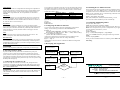
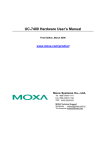
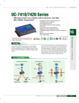
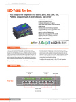
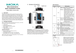
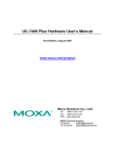
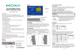
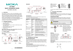
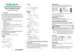
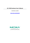
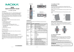
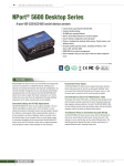
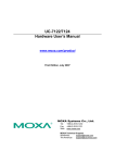
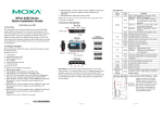
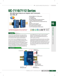
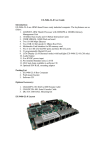
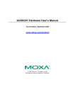
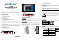
5. Connector Description
Top View
Power Connector
Connect the 12-48 VDC power line to UC-8410’s terminal block. If the
power is properly supplied, the Ready LED will glow a steady green color
when the OS is ready.
UC-8410
Quick Installation Guide
Grounding the UC-8410
Grounding and wire routing help limit the effects of noise due to
electromagnetic interference (EMI). Run the ground connection from the
ground screw to the grounding surface prior to connecting the power.
First Edition, October 2008
1. Overview
The UC-8410 features 8 RS-232/422/485 serial ports, 3 10/100 Mbps
Ethernet ports, 4 digital input and 4 digital output channels, and
CompactFlash and USB ports for adding additional memory. All of these
features make the UC-8410 ideal for your embedded applications.
ATTENTION
This product is intended to be mounted to a well-grounded mounting surface,
such as a metal panel.
Front View
Reset Button
SG: The Shielded Ground (sometimes called Protected
Ground) contact is the left most contact of the 3-pin
power terminal block connector when viewed from the
angle shown here. Connect the SG wire to an
appropriate grounded metal surface.
2. Package Checklist
Before installing the UC-8410, verify that the package contains the following
items:
USB 2.0 Host x 2
Serial Port x 8, RJ45
(RS-232/422/485)
y 1 UC-8410 embedded computer
y Wall-Mounting Kit
4. Installing the UC-8410
y DIN-Rail Mounting Kit
Wall or Cabinet
The two metal brackets included with the UC-8410 can be used to attach it to
a wall or the inside of a cabinet. Using two screws per bracket, first attach the
brackets to the bottom of the UC-8410. Next, use two screws per bracket to
attach the UC-8410 to a wall or cabinet.
y UC-8410 Quick Installation Guide (this guide)
y UC-8410 Document & Software CD
y Cross-over Ethernet cable
y CBL-RJ45M9-150: 150 cm, 8-pin RJ45 to DB9 male serial port cable
y CBL-4PINDB9F-150: 4-pin pin header to DB9 female console port cable,
150 cm
y Universal power adaptor (includes terminal block to power jack converter)
y Product Warranty Sheet
Note: Please notify your sales representative if any of the above items are
missing or damaged.
DIN-Rail Mounting
The aluminum DIN-Rail attachment plate is included in the package. To
attach the plate to the UC-8410, situate the stiff metal spring towards the top.
STEP 1: Insert the top of the
STEP 2: The DIN-Rail attachment
DIN-Rail into the slot just below the unit will snap into place as shown
stiff metal spring.
below.
metal
spring
3. UC-8410 Panel Layout
Refer to the following figures for UC-8410 panel layout.
metal
spring
SG
Ethernet Port
The 2 10/100 Mbps Ethernet ports (LAN 1 and LAN 2) use RJ45 connectors.
Pin
1
2
3
6
Signal
ETx+
ETxERx+
ERx-
LED Indicators
DI Channel x 4
DIN-Rail
DIN-Rail
10/100 Mbps
Ethernet x 3
DO Channel x 4
To remove the UC-8410 from the DIN-Rail, reverse Steps 1 and 2 above.
Power Input
12 to 48 VDC
8
Serial Port
The 8 serial ports (P1 to P8) use RJ45 connectors. Each port can be
configured by software as RS-232, RS-422, or RS-485. The pin assignments
are shown in the following table:
Pin
RS-232
1
2
3
4
5
6
7
8
DSR
RTS
GND
TXD
RXD
DCD
CTS
DTR
Rear View
(Power, SRAM Battery,
Ready, Storage)
1
RS-422/
RS-485-4W
--TXD+
GND
TXDRXD+
RXD-----
RS-485
----GND
--Data+
Data-----
P/N: 1802084000010
—1—
—2—
—3—
1
8
CompactFlash
The UC-8410 provides one CompactFlash slot that supports CompactFlash
type I/II card expansion. Currently, Moxa provides a CompactFlash card for
storage expansion. Be sure of power off the computer before inserting or
removing the CompactFlash card. The CompactFlash is be mounted at
/mnt/sda.
Console Port
The serial console port is a 4-pin pin-header RS-232 port. It is used for the
serial console terminal, which is useful for viewing boot-up messages. Use
the CBL-4PINDB9F-100 cable included with the UC8410-LX to connect a
PC to the UC-8410’s serial console port.
Reset Button
Press the “Reset” button continuously for at least 5 seconds to load the
factory default configuration. After the factory default configuration has been
loaded, the system will reboot automatically. The Ready LED will blink on
and off for the first 5 seconds, and then maintain a steady glow once the
system has rebooted.
USB
The USB 2.0 Host port now supports a USB storage device driver. The
USB1.1 Client port is reserved for future enhancement.
Real Time Clock
The UC-8410’s real time clock is powered by a lithium battery. We strongly
recommend that you do not replace the lithium battery without help from a
qualified Moxa support engineer. If you need to change the battery, contact
the Moxa RMA service team.
ATTENTION
There is a risk of explosion if the battery is replaced by an incorrect type.
To use Telnet you will need to know the UC-8410’s IP address and netmask.
The default LAN settings are shown below. For first-time configuration, you
may find it convenient to use a cross-over Ethernet cable to connect directly
from the PC to the UC-8410.
Default IP Address
Netmask
192.168.3.127
255.255.255.0
LAN 1
192.168.4.127
255.255.255.0
LAN 2
192.168.5.127
255.255.255.0
LAN 3
Once the UC-8410 is powered on, the Ready LED will light up, and a login
page will open. Use the following default Login name and Password to
proceed.
Login: root
Password: root
10. Installing the UC-8410 Tool Chain
The PC must have the Linux operating system pre-installed to install the
UC-8410 GNU Tool Chain. Redhat 7.3/8.0, or Linux Kernel 2.4.18 and
compatible versions are recommended. The Tool Chain will use about 400
MB of your PC’s hard disk space. Use the following command to install the
Tool Chain from the UC-8410 CD:
#mount /dev/cdrom /mnt/cdrom
#sh /mnt/cdrom/tool-chain/linux/arm-linux_2.0.sh
The Tool Chain will be installed on your PC automatically.
11. Compiling and Running Hello.c
The path to the Tool Chain is:
PATH=/usr/local/arm-linux/bin:$PATH
8. Configuring the Ethernet Interface
If you use the console cable for first-time configuration of the network
settings, use the following commands to edit the interfaces file:
The UC-8410 CD also includes several example programs. Here we use
Hello.c as an example to show you how to compile and run your applications.
Type the following commands on your PC:
#ifdown –a
//Disable LAN1/LAN2/LAN3 interface first, before you
reconfigure the LAN settings. LAN 1 = eth0, LAN 2= eth1//
#vi /etc/network/interfaces
//check the LAN interface first//
# cd /tmp/
# mkdir example
# cp –r /mnt/cdrom/example/* /tmp/example
After the boot setting of the LAN interface has been modified, use the
following command to activate the LAN settings immediately:
#make
#sync ; ifup –a
NOTE: Refer to the UC-8410 User’s Manual for additional configuration
information.
Next, go to the Hello subdirectory and type the following command:
to finish compiling Hello.c.
Finally, run the executable file that was created to generate hello-release and
hello-debug.
9. Developing Your Application
Power on the target and
connect to Linux PC.
6. Powering on the UC-8410
To power on the UC-8410, connect the “terminal block to power jack
converter” to the UC-8410’s DC terminal block (located on the left rear
panel), and then connect the power adaptor. Note that the Shielded Ground
wire should be connected to the right most pin of the terminal block. It takes
approximately 30 seconds for the system to boot up. Once the system is ready,
the Ready LED will light up.
Install GNU cross
compiler on Linux PC
Install Glibc on
Linux PC
Set up cross compiler
and Glibc environment
variables
Code program
and compile
Install GDB client on
Linux PC (optional)
Download to target to
run and test
7. Connecting the UC-8410 to a PC
There are two ways to connect the UC-8410 to a PC, through the serial
console port or by Telnet over the network. The COM settings for the serial
console port are: Baudrate=115200 bps, Parity=None, Data bits=8, Stop
bits =1, Flow Control=None.
No
New
Program
Develop end user
application
Yes
Program
Debugged?
ATTENTION
Remember to choose the “VT100” terminal type. Use the CBL-RJ45F9-150
cable included with the product to connect a PC to the UC-8410’s serial
console port.
—4—
Click here for online support:
www.moxa.com/support
The Americas:
Europe:
Asia-Pacific:
China:
+1-714-528-6777 (toll-free: 1-888-669-2872)
+49-89-3 70 03 99-0
+886-2-8919-1230
+86-21-5258-9955 (toll-free: 800-820-5036)
© 2008 Moxa Inc. All rights reserved.
Reproduction without permission is prohibited.
—5—
—6—