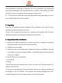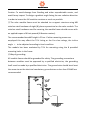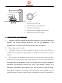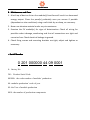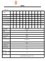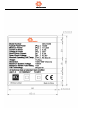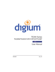
1
ORI Solar Limited
USER MANUAL
Please read this manual carefully before installing and using the modules.
It is the great honor to provide you with our PV modules. In order to enable the
PV module to be installed correctly and to generate electric power properly,
please read the following operation instruction carefully.
1. Warning:
1 ) . Artificially concentrated sunlight shall not be directed on the module or
panel.
2 ) . Under normal conditions, a photovoltaic module is likely to experience
conditions that produce more current and/or voltage than reported at standard
test conditions. Accordingly, the value of Isc and Voc marked on this module
should be multiplied by of 1.25 when determining component voltage ratings,
conductor current ratings, fuse sizes, and size of controls connected to the PV
output.
3). Do not touch live terminals with bare hands. Use insulated tools for electrical
connections.
4). To reduce the risk of electrical shock or burns, modules may be covered with
an opaque material during installation to avoid shocks or burns.
5). The installation work of the PV array can only be done under the protection
of sun-sheltering covers or sunshades and only qualified person can install or
perform maintenance work on this module.
6 ) . Follow the battery manufacture’s recommendations if batteries are used
with modules.
7).Fire safety. Refer to your local authority for guidelines and requirements for
building or structural fire safety; The roof construction and installation may
affect the fire safety of a building, improper installation may contribute to
hazards in the event of fire; Use earth ground fault circuit breakers, fuses and
ORI Solar Limited
circuit breakers as required or necessary; Do not use modules near equipment
where flammable gases can be generated or can collect; The modules are rated
fire Class C and are suitable for mounting over a Class A roof.
8). All instructions should be read and understood before attempting to install,
wire, operate and maintain the module.
2. Unpacking
After the PV module has been shipped to the installation site all of the parts
should be unpacked properly with care.
Caution: The condign environment for unpacking the modules and all other
apparatus should be proofed against dampness and rainfall.
3. Preparation before Installation:
1. Optical check before installation, to make sure there is no bug in the packing
and junction box as well as the surface of module.
2. Check the series number
3. Check the solar cell modules with irradiance of more than 600W/m2 and get
the voltage. In case the voltage is ZERO, it should NOT be installed and please
contact the supplier.
4. Tools & Material for Installation
① Screwdriver
② Clamp
③Each mounting hole matches with a set of a screw, a nut and two washer, all
made of stainless iron.
④ The users should design and build metallic bracket for installing and bearing
the weight of the PV modules. The brackets are specially designed for users’
installation places such as the open land or on the roof of houses.
ORI Solar Limited
Caution: To avoid damage from flooding and other unpredictable events, and
avoid heavy impact. To design a gradient angle facing the sun radiation direction
in order to insure the full sunshine receives as much as possible.
⑤ The solar module frame must be attached to a support structure using M8
stainless steel hardware of eight (8) places symmetrical on the solar module. The
stainless steel hardware used for securing the module frame should secure with
an applied torque of 6 foot-pounds (8 Newton-meters).
The recommended standoff height is 20 cm. If other mounting means are
employed this may affect the TUV Listing or the fire class ratings, the incline
angle α to be adjusted according to local condition.
The module has been evaluated by TUV for mounting using the 8 provided
mounting holes in the frame.
⑥Way of grounding:
All module frames should be grounded for safety. The grounding connections
between modules must be approved by a qualified electrician, the grounding
itself must be made by a qualified electrician. The ground wire should be at least
the same size as the electrical conductors, ground wires no less than 12AWG are
recommended.
A
A
ORI Solar Limited
3
1
2
3
4
5
4
WASHER
1. Stainless steel M4 nut
2. Stainless steel serrated washer
3. Stainless steel washer
4. Stainless steel cupped-shape washer
5. Stainless steel M4 t-head bolt
4. INSTALLATION AND OPERATION
1 ) . Systems should be installed by qualified personnel only and at least two
persons. The system involves electricity, and can be dangerous if the
personnel are not familiar with the appropriate safety procedures.
2). Do not step on the module.
3 ) . Although modules are quite rugged, the glass can be broken (and the
module will no longer work properly) if it is dropped or hit by tools or other
objects.
4 ) . Put the solar cell modules on the frame and put on the screws and then
combine them firmly after put on all the gaskets. All the screw caps should be
finished on the frame together firmly. The module frame is made of anodized
aluminum, and therefore corrosion can occur if the module is subject to a
salt-water environment with contact to a rack of another type of metal.
(Electrolysis Corrosion) if required. PVC or stainless steel washers can be
placed between the solar module frame and support structure to prevent this
ORI Solar Limited
corrosion.
5). The solar module frame must be attached to a support structure using M8
stainless steel hardware in a minimum of eight (8) places symmetrical on the
solar module. The stainless steel hardware used for securing the module
frame should secure with an applied torque of 6 foot-pounds (8
Newton-meters).
6). Module support structures that are to be used to support modules should be
wind rated and approved for use by the appropriate local and civil codes prior
to installation.
7 ) . When solar modules are used to charge batteries, the battery must be
installed in a manner, which will protect the performance of the system and
the safety of its users. Follow the battery manufacturer’s guidelines
concerning installation, operation and maintenance recommendations. In
general, the battery (or battery bank) should be away from the main flow of
people and animal traffic. Select a battery site that is protected from sunlight,
rain, snow, debris, and is well ventilated. Most batteries generate hydrogen
gas when charging, which can be explosive. Do not light matches or create
sparks near the battery bank. When a battery is installed outdoors, it should
be placed in an insulated and ventilated battery case specifically designed for
the purpose.
8). In most applications, PV modules should be installed in a location where they
will receive maximum sunlight throughout the year. In the Northern
Hemisphere, the modules should typically face south, and in the Southern
Hemisphere, the modules should typically face north. Modules facing 30
degrees away from true South (or north) will lose approximately 10 to 15
percent of their power output. If the module faces 60 degrees away from true
South (or North), the power loss will be 20 to 30 percent. When choosing a
ORI Solar Limited
site, avoid trees, buildings or obstructions, which could cast shadows on the
solar.
5. Wiring and Connection:
1. Before this procedure, please read the operation instructions of the PV
control system carefully.
2. The cable diameter is 4mm2 ,type is PV1-F, 1*4.0mm2.Max. Temperature at
conductor is 120℃, Ambient Temperature is -40℃~+90℃. Manufacturer is
CiXi Renhe Photovoltaic Electrical Appliance Co., LTD.
3. Make wiring by Multi-connecting cables between the PV modules in series or
parallel connection, which is determined by user’s configuration requirement
for system power, current and voltage.
4. Open the connection box of the control system and connect the cabled from
the PV arrays to the connection box in accordance with the installation
indication of the PV control systems.
5. All module frames and mounting racks must be properly grounded in
accordance with local and national electrical codes.
6. Do not use modules of different configurations in the same system. The
maximum number of modules connected in series (N) = Vmax system / [Voc
(at STC)]. The maximum number of modules connected in parallel is not
limited, this is determined by the system design such as desired current or
power output etc. Several modules are connected in series and then in
parallel to form a PV array, especially for application with a high operation
voltage. If modules are connected in series, the total voltage is equal to the
sum of individual voltages.
7. Follow the requirements of applicable local and national electrical codes.
ORI Solar Limited
8. Maintenance and Care:
1. A built up of dust or dirt on the module(s) front face will result in a decreased
energy output. Clean the panel(s) preferably once per annum if possible
(dependant on site conditions) using a soft cloth dry or damp, as necessary.
2. Never use abrasive material under any circumstances.
3. Examine the PV module(s) for signs of deterioration. Check all wiring for
possible rodent damage, weathering and that all connections are tight and
corrosion free. Check electrical leakage to ground.
4. Check fixing screws and mounting brackets are tight, adjust and tighten as
necessary.
●Serial Number
0 201 000000 44 09 0001
0:factory No.
201:Product Serial Code
000000:the order number of modules’ production
44: modules production’ week of year
09: the Year of module production
0001: the number of production components
ORI Solar Limited
Date sheet for all module types of the family
ORI 175M-A01 Series:
Parameters
ORI 160M-A01
ORI 165M-A01
ORI 170M-A01
ORI 175M-A01
ORI 180M-A01
ORI 185M-A01
ORI 190M-A01
160±3%
165±3%
170±3%
175±3%
180±3%
185±3%
190±3%
Open circuit voltage Voc(V)
42.7
42.7
43.2
43.2
43.9
43.9
44.5
Max. power voltage Vmp(V)
35
35
35.5
35.5
36
36
36.5
Max. power current Imp(A)
4.57
4.71
4.79
4.93
5.0
5.14
5.21
Short circuit current Isc(A)
4.98
5.13
5.27
5.52
5.60
5.70
5.75
12.6%
13.0%
13.4%
13.8%
14.2%
14.6%
14.8%
Peak power Pm(W)
Practical Module Efficiency ηc(%)
Dimensions(L*W*H)
Weight(kg)
Maximum Series Fuse Rating(A)
Max. system voltage (V)
Application Class
Mono crystalline silicon solar cell
No. of cells and connections
1580×808×35
15.5
10
1000V DC
Class A
125*125*0.19mm
72 series
No. of bypass diodes
3
Bypass diode rating (A)
10
Bypass diode max. junction
temperature(℃)
Bypass diode thermal
resistance(℃/W)
STC
200
3.0
Irradiance:1000W/m2,Cell temperature:25℃,AM:1.5
ORI Solar Limited
ORI 230P-F02 Series:
ORI
ORI
ORI
ORI
ORI
ORI
ORI
ORI
ORI
ORI
ORI
200P-F02
205P-F02
210P-F02
215P-F02
220P-F02
225P-F02
230P-F02
235P-F02
240P-F02
245P-F02
250P-F02
200±3%
205±3%
210±3%
215±3%
220±3%
225±3%
230±3%
235±3%
240±3%
245±3%
250±3%
Open circuit voltage Voc(V)
35.5
35.5
36.1
36.1
36.1
36.7
36.7
37.3
37.3
37.3
37.9
Max. power voltage Vmp(V)
28.6
28.6
29.1
29.1
29.1
29.6
29.6
30.1
30.1
30.1
30.6
Max. power current Imp(A)
6.99
7.17
7.22
7.39
7.56
7.60
7.77
7.82
7.97
8.14
8.18
Short circuit current Isc(A)
7.55
7.74
7.79
7.98
8.16
8.21
8.39
8.45
8.61
8.79
8.85
12.2%
12.5%
12.8%
13.1%
13.4%
13.7%
14.1%
14.3%
14.7%
15.0%
15.3%
Parameters
Peak power Pm(W)
Practical Module Efficiency
ηc(%)
Dimensions(L*W*H)
Weight(kg)
Maximum Series Fuse Rating(A)
Max. system voltage (V)
Application Class
1650*992*50
19.5
15
1000V DC
Class A
Mono crystalline silicon solar
cell
156*156*0.19mm
No. of cells and connections
60 series
No. of bypass diodes
6
Bypass diode rating (A)
10
Bypass diode max. junction
temperature(℃)
Bypass
diode
thermal
resistance(℃/W)
STC
200
3.0
Irradiance:1000W/m2,Cell temperature:25℃,AM:1.5
ORI Solar Limited
ORI 270P-K02
Series:
Parameters
ORI 250P-K02
ORI 255P-K02
ORI 260P-K02
ORI 265P-K02
ORI 270P-K02
ORI 275P-K02
ORI 280P-K02
ORI 285P-K02
ORI 290P-K02
250±3%
255±3%
260±3%
265±3%
270±3%
275±3%
280±3%
285±3%
290±3%
Open circuit voltage Voc(V)
43.5
43.5
43.5
43.9
43.9
43.9
44.8
44.8
44.8
Max. power voltage Vmp(V)
35.1
35.1
35.1
35.6
35.6
35.6
36.1
36.1
36.1
Max. power current Imp(A)
7.12
7.26
7.41
7.44
7.59
7.72
7.76
7.89
8.03
Short circuit current Isc(A)
7.69
7.85
7.98
8.04
8.20
8.34
8.38
8.53
8.67
12.8%
13.3%
13.8%
14.3%
14.8%
14.3%
14.8%
15.3%
15.8%
Peak power Pm(W)
Practical Module Efficiency
ηc(%)
Dimensions(L*W*H)
Weight(kg)
Maximum Series Fuse Rating(A)
Max. system voltage (V)
Application Class
Mono crystalline silicon
solar cell
No. of cells and connections
No. of bypass diodes
Bypass diode rating (A)
Bypass diode max. junction
temperature(℃)
Bypass
diode
thermal
resistance(℃/W)
STC
1957*992*50
22.5
15
1000V DC
Class A
156*156*0.19mm
72 series
6
10
200
3.0
Irradiance:1000W/m2,Cell temperature:25℃,AM:1.5
ORI Solar Limited
ORI Solar Limited
ORI Solar Limited