1
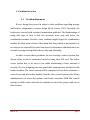
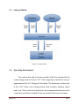
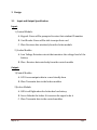
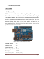
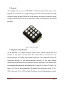
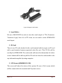
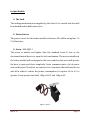
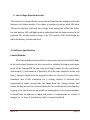
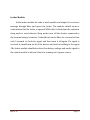
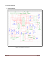
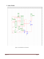
Project:RepriseofLockerAccess System (FinalReport) _____________________________________________ GroupMay14–12 MohammedAlKaabi SherryElsaGungat NurulIzniHazimiAbdulAziz ShichaoSu Client IowaStateUniversity(ECPE) Advisor Harker,LelandEdward TableofContents 1.ProblemOverview 1.1ProblemStatement‐‐‐‐‐‐‐‐‐‐‐‐‐‐‐‐‐‐‐‐‐‐‐‐‐‐‐‐‐‐‐‐‐‐‐‐3 2.SystemOverview 2.1SystemRequirement‐‐‐‐‐‐‐‐‐‐‐‐‐‐‐‐‐‐‐‐‐‐‐‐‐‐‐‐‐‐‐‐‐‐4 2.2SystemBlockDiagram‐‐‐‐‐‐‐‐‐‐‐‐‐‐‐‐‐‐‐‐‐‐‐‐‐‐‐‐‐‐‐‐‐5 2.3ConceptSketch‐‐‐‐‐‐‐‐‐‐‐‐‐‐‐‐‐‐‐‐‐‐‐‐‐‐‐‐‐‐‐‐‐‐‐‐‐‐‐‐‐‐6 2.4OperatingEnvironment‐‐‐‐‐‐‐‐‐‐‐‐‐‐‐‐‐‐‐‐‐‐‐‐‐‐‐‐‐‐‐6 3.Design 3.1InputandOutputSpecification‐‐‐‐‐‐‐‐‐‐‐‐‐‐‐‐‐‐‐‐‐‐7 3.2HardwareSpecification‐‐‐‐‐‐‐‐‐‐‐‐‐‐‐‐‐‐‐‐‐‐‐‐‐‐‐‐‐‐‐9 3.3SoftwareSpecification‐‐‐‐‐‐‐‐‐‐‐‐‐‐‐‐‐‐‐‐‐‐‐‐‐‐‐‐‐‐‐‐14 3.4CircuitSchematic‐‐‐‐‐‐‐‐‐‐‐‐‐‐‐‐‐‐‐‐‐‐‐‐‐‐‐‐‐‐‐‐‐‐‐‐‐‐16 3.5Cost‐‐‐‐‐‐‐‐‐‐‐‐‐‐‐‐‐‐‐‐‐‐‐‐‐‐‐‐‐‐‐‐‐‐‐‐‐‐‐‐‐‐‐‐‐‐‐‐‐‐‐‐‐‐‐18 4.Standard‐‐‐‐‐‐‐‐‐‐‐‐‐‐‐‐‐‐‐‐‐‐‐‐‐‐‐‐‐‐‐‐‐‐‐‐‐‐‐‐‐‐‐‐‐‐‐‐‐‐‐‐‐‐‐‐‐‐‐‐‐19 5.Testing‐‐‐‐‐‐‐‐‐‐‐‐‐‐‐‐‐‐‐‐‐‐‐‐‐‐‐‐‐‐‐‐‐‐‐‐‐‐‐‐‐‐‐‐‐‐‐‐‐‐‐‐‐‐‐‐‐‐‐‐‐‐‐‐19 AppendixI‐‐‐‐‐‐‐‐‐‐‐‐‐‐‐‐‐‐‐‐‐‐‐‐‐‐‐‐‐‐‐‐‐‐‐‐‐‐‐‐‐‐‐‐‐‐‐‐‐‐‐‐‐‐‐‐‐‐‐‐‐‐‐22 AppendixII‐‐‐‐‐‐‐‐‐‐‐‐‐‐‐‐‐‐‐‐‐‐‐‐‐‐‐‐‐‐‐‐‐‐‐‐‐‐‐‐‐‐‐‐‐‐‐‐‐‐‐‐‐‐‐‐‐‐‐‐‐‐24 May14‐12 Page2 1. ProblemOverview 1.1 ProblemStatement We are doing this project in order to solve problem regarding storage and lockers assignment in senior design lab in Coover 1301. Currently, the lockersaresecuredwithstandardcombinationpadlocks.Thedisadvantageof using this type of lock is that the previous users may still know the combination number. Besides, some students might forget the combination numberfortheirteam’slocker.Otherthanthat,thepadlockisnotintuitiveor noteasytouseespeciallyforfirsttimeusers.Furthermore,administratorsare notabletoassignandupdatelockerseasilyandefficiently. Inordertosolvetheseproblems,wearecreatingacontrolsystemthat allows locker access to authorized users by using their ISU card. The locker access system has to be easy to use while maintaining a basic amount of security.Wearedesigningoneuserpanelthatcommunicateswirelesslywith lockermodules.Theentiresystemwillbecomprisedoftwobasicelements:a control box, and the locker module. Besides, this control system also allows administrators to access list updates and locker overrides. With this control system,itwillbeeasierandsaferforstudentstostoretheirprojectandaccess theirlockers. May14‐12 Page3 2. SystemOverview 2.1 SystemRequirement The system will the read magnetic strip on the student ID card andunlockthecorrespondingdoor.Besides,italsoallowsmanual entryonthekeypadonthecontrolbox. It must allow administrative functionality including access list updatesandlockeroverrides. The user panel must have a display that shows the status of the system. It will give direction to user whenever they use this system. The user panel will communicate wirelessly with the locker modules. The wireless communication must be in two ways communication so that the user panel can send and receive data to locker module in order to open the door. Similarly, locker module can send information to the user panel regarding the status of the battery in each locker module. The wireless data transmission needs to have the ability to transmit data from the longestdistanceoratleastcoverthebigrangeofthedimensionof theroom. Thebatterymustlastatleastonesemesterandthelockermodule needstogivewarningwhenthebatteryisat50%orlower. TheSDcardmustbeabletoreadandstoredatabaseofnamesand locker numbers so that it can be updated easily by using computers. May14‐12 Page4 2.2SystemBlockDiagram Figure 1: Block Diagram May14‐12 Page5 2.3 ConceptSketch Figure 2: Concept Sketch 2.4 OperatingEnvironment Thecontrolboxandthelockermodulewillbelocatedinsidethe seniordesignroominCoover1301.Thetemperatureinsidethisroomis approximately69to74degreesFahrenheit.Thedimensionoftheroom is 44’ x 28’. It has a lot of things inside such as tables, desktop, chairs andsoon.Thesecanbetheobstacleforthecommunicationbetweenthe controlboxandlockermoduleiftheyaresituatedfarfromeachother. May14‐12 Page6 3 Design 3.1 InputandOutputSpecification Input: 1) ControlModule: A. Keypad‐UserswillbepromptedtoentertheirstudentIDnumber B. Card‐Reader‐Userswillbeabletoswipetheircard C. Xbee‐Receivesdatawirelesslyfromthelockermodule 2) LockerModule: A. LowVoltageDetection‐circuitthatmonitorsthevoltagelevelofthe battery B. Xbee‐Receivesdatawirelesslyfromthecontrolmodule Output: 1)ControlModule: A. LCDScreen‐outputsdatainauserfriendlyform B. Xbee‐Transmitsdatatothelockermodules 2)LockerModule: A. LED‐itwilllightwhenthelockerhaslowbattery B. Servo‐Unlocksthelockerifitreceivesthesignaltodoit C. Xbee‐Transmitsdatatothecontrolmodules May14‐12 Page7 Input/Output: A. Xbee ‐Receives and transmits signals both ways (Communication betweencontrolmoduleandlockermodule) B. SDCard‐ThiswillbeinputandoutputintheControlmodule.Names,ID number,andlockernumberwillbestoredhere May14‐12 Page8 3.2HardwareSpecification ControlModule Microcontroller Both locker and control modules will be using ATmega328 microprocessor. All code for our microcontrollers is written in the Arduino Processing C Programmer/Compiler.TheATMEGA328isa28pinsmicrocontrollerthatwill beabletoberemovedandreprogramlaterbyusingArduinoUno.Thisisan important feature since most of the locker module will need to be programmedwiththeiridentifiersbeforetheycanbeinstalled.Belowarethe specificationsofthemicrocontroller: Figure 3: Arduino Uno (WIth Atmega 328 Processor) OperatingVoltage:5V DigitalI/OPins:14 AnalogInputPins:6 DCCurrentperI/OPin:40mA ClockSpeed:16MHz PowerConsumption:0.21W(at5V) May14‐12 Page9 WirelessCommunication Forwirelesscommunication,weareusingXbee1mWTraceAntenna–Series 1(802.15.4). This module takes the 802.15.4 stack and allows very reliable and simple communication between microcontrollers. This module can be programmedeasilybyX‐CTU.Wesetalltransmissionisdoneinserialformat at9600baud,noparitybit,andnostopbitandsetalltheXbeesinthesameIP address. We also use the same Xbee as the receiver and transmitter in the lockermodules.ThespecificationsfortheXbeeisshownbelow: Figure 4: Xbee Series 1 Indoorrange:upto100ft(30m) OutdoorRange:upto300ft(100m) Transmitpower:1mW SupplyVoltage:2.8‐3.4V TransmitCurrent:45mAat3.3V Receive/idlecurrent:50mAat3.3V PowerConsumption:0.15Wat3.3V(forTransmit) May14‐12 :0.17Wat3.3V(forReceive) Page10 Keypad The keypad that we use is COM‐08653, 12 button keypad. The pins of the keypad are connected to a single analog pin of the microcontroller by using voltage‐resistormethod.Whenoneofthebuttonsispressed,aspecificanalog voltageismeasuredatthemicrocontroller,whichcorrespondstothebutton pressed. Figure 5:12‐Button Keypad MagneticStripeReader An AP‐MSR200 is a simple magnetic stripe reader, which outputs the card number in the form of serial data. The card reader is connected to the microcontroller via female DB9 female connector. The connector cannot be connected directly to the microcontroller because of the large voltage differentialbetweenthemicrocontrollerandtheconnector.Thiscausesissue incommunicatingwiththemicrocontroller.Alogical0orlowis0Vanda1or highis+5Vforthemicrocontroller.Meanwhile,theconnectorsends ‐3Vto ‐ 25Vaslowand+3Vto+25Vforhigh.Therefore,alevelshiftingchipisneeded. May14‐12 Page11 Figure 6: Magnetic Card Reader LevelShifter We use a MAX232CPE in order to turn the serial output to TTL (Transistor‐ Transistor Logic). Once it’s in TTL form, we can read it at the ATMEGA328 serialinput. SDCard ThereisoneSDcardattachedtothecardterminalwhichacceptsanSDcard with a pre‐formatted comma separated value file on it. This CSV file will be readbytheATMEGA328.Thecardreaderwillstoretheinformationforlocker access.AdminwillbeabletopulltheSDcardoutfromthecardmoduletodo anyinformationupdatebyusingcomputer. LCDScreen(ADM2004D‐FL‐YBS) The screen will show the status of the system. We use a 20x4 screen which willbeconnectedtotheterminaland5Vpowersource. May14‐12 Page12 LockerModule TheLock Thelockingmechanismwassuppliedbytheclient.Itisametallockthatwill beunlockedandlockedbytheservo. PowerSource Thepowersourceforthelockermoduleisbatteries.Wewillbeusingfour1.5 VAAbatteries. Servo‐900‐00014 This servo is smaller and lighter than the standard servo. It acts as the electromechanicaldevicetoopenthelockmechanism.Themicrocontrollerin thelockermodulewillsendsignaltotheservoandthentheservowilloperate the door to open and close completely. Servo consumes quite a lot of power eveninidlestate.Therefore,weconnectittoatransistorthatwillswitchiton and off in order to reduce the power consumption. It requires 4.8 to 6 V to operate.Itcanoperateloadwith1.2kgat4.8Vand1.4kgat6V. Figure 7: Servo May14‐12 Page13 LowVoltageDetectionCircuit Thiscircuitisavoltagedividercircuitthatwillmonitorthevoltagelevelinthe batteries for locker module. The values of resistors used are both 10k ohm. The microcontroller will read the voltage from analog pin. When the locker haslowbattery,LEDwilllightupasanindicationthatthebatteriesneedtobe replaced. We set the lowest voltage to be 3.0V and the LED should light up whenthebatteryreachesthislevel. 3.3SoftwareSpecification ControlModule: Alloftheinitializationneededforconnectionsanddeviceswillbedone inthevoidsetup()function.Atfirst,weneedtoinitializetheinputandoutput ports of the Atmega328. In our code, void loop() stands for the void main() withawhile(1)statementinit.Basically,allofthecodeshouldbeinthevoid loop()function.Inputfromthekeypadistakenasaformof0‐5voltswhich translates into 10‐Bit resolution via a voltage divider. A function char keypressed(int input) should take the input from the voltage divider and returnthekeypressedinaformofcharacter.intsendData(intlockerNumber) isgoingtobethefunctionresponsibleofsendingdatatothelockermodules. It should take an address as input and return a conformation as a form of integer(ex1=done,2=lowbatteryand0=connectionfailed). May14‐12 Page14 LockerModule: Inthelockermodulethecodeismuchsmallerandsimpler.Itreceivesa message through Xbee and opens the locker. The module should return a confirmationthatthelockerisopened.Whileidle,itshouldputthesystemin sleep mode to save batteries. Sleep mode turns off the devises connected to theterminalusingatransistor.ItshouldturnontheXbeeforasecondatleast each 5 seconds to check for signal and then turns it off again. If a signal is received,itshouldturnonallofthedevicesandworkaccordingtothesignal .Thelockermoduleshouldalsodetectlowbatteryvoltageandsendasignalto thecontrolmoduletoinformitthatitisrunningoutofpowersource. May14‐12 Page15 3.4CircuitSchematic ControlModule Figure 8: Control Module Circuit Schematic May14‐12 Page16 LockerModule Figure 9: Locker Module Circuit Schematic May14‐12 Page17 3.5 Cost Parts and Materials Unit price Quantity Total Atmega328 $5.50 2 $11.00 Xbee series 1 $22.95 2 $45.90 Keypad (COM08653) $13.95 1 $13.95 LCD Screen (ADM2004D‐FL‐YBS) $17.62 1 $17.62 SD card $9.95 1 $9.95 Magnetic card reader $44.95 1 $44.95 Servo (900‐00014) $10.95 1 $10.95 $10 1 $10.00 VoltageRegulator(5V) $0.95 1 $0.95 VoltageRegulator(3.3V) $1.95 1 $1.95 NpnTransistor $0.50 1 $0.50 Resistors $0.25 14 $3.50 Capacitors $0.45 4 $1.80 16MHzCrystal $0.95 2 $1.90 MAX232CPE $1.85 1 $1.85 Lock Total May14‐12 $176.77 Page18 4 Standard Xbee The standard for the Xbee that we are using is IEEE 802.15.4. This standard focuses on a low cost wireless communication of nearby devices. It is suitable for our project because the two Xbees (one in Control module and another one in Locker module) will be communicatinginaclosedistance. 5 TestingProcessandResult In order to test the design, we tested it by part. Once we are done with one part and confirm that it is working properly and reliably, we proceed with another part. Then, after testing component by component, we tested the wholesystem. Keypad We tested the keypad by connecting it to analog pin 5 of the microprocessor.LCDscreenwilldisplaythebuttonthatisbeingpressed and the analog voltage corresponding to the button. We pressed one buttonatatimeandweverifiedthattheLCDscreenshowsthecorrect button.Itdemonstratesthatthekeypadworks. SDCard WetestedtheSDcardbystoringourinformation(studentIDnumber) into it by using computer and then connected the SD card to the May14‐12 Page19 microprocessor. The microprocessor is also connected to the keypad and LCD screen. After we typed in our student ID number on the keypad,theLCDscreendisplays’studentIDmatched’.Itshowsthatthe SDCardisabletocommunicatewiththemicroprocessor. WirelessCommunication We use Xbee for wireless communication. We tested it by connecting oneXbeetothelockermoduleandanotheronetothecontrolmodule. Firsty,wetestedthecommunicationwiththetwoXbeeareplacedclose to each other. Then, we increased the distance of communication to 20m. From this two testing, we verified the Xbee can communicate efficientlyforbothnearandfardistance. Testingthewholesystem Inordertotestthewholesystem,weuseonecontrolmoduleandthree locker module. We sent signal to each locker module from the control module. When we send signal to locker 1, the servo will unlock the locker. This indicates that the control module are able to differentiate eachlockermoduleandcommunicatewiththecorrectlocker. May14‐12 Page20 AppendixI OperationManual There are two different user manual for the two intended users which are studentsandadministrators. Students: 1. Swipe ISU card on the card reader or type student ID number on the keypad. 2. Lockerassociatedwiththestudentwillbeunlocked. Admins: 1. SwipeISUcardonthecardreaderortypeIDnumberonthekeypad.A message“WelcomeAdmin”willappear. 2. Adminwillbepromptedtochooseoneofthetwooptions: A. Openspecificlocker: 1. Choosealockertobeopened.Ifthelockernumberis less than 10, type ‘0’ before the locker number. For example,type“06”inordertoopenlockernumber6. B. AddnewUser: 1. Type in new user’s ID number. A message of confirmationwillappear. May14‐12 Page21 2. A new message will appear to the admin, "ADMIN? 1=YES,0=NO".Amessageofconfirmationwillappear which displays the result of adding the new user to thesystem.(1isforadminand0isforstudent). 3. If the new user is student, specify which locker the student will have access to. If the locker number is less than 10, type ‘0’ before the locker number. For example,type“06”toassignlockernumber6. Ifadminchooseoptionotherthan1and2,thesystemwilldisplayamessage saying“WrongOption”andadminwillbeaskedtochooseanewoptionagain. Alternativeforadmin Admin will also be able to take the SD card out from the Control Module in order to add new user and new locker. There are two files saved in the SD cardwhichare“user”and“locker”. I. Addnewuser 1. PlugtheSDcardintoacomputer. 2. Choosefileuser. 3. Addanewlineforeachnewuserinthisformat: ID,Admin,lockerNumbere.g.“976431456,1,01” 1isforadminand0isforstudent. May14‐12 Page22 II. Addnewlocker 1. PlugtheSDcardintoacomputer. 2. Choosefilelocker. 3. Savethenewlockeraddedinthisformat: lockerNumber,SH,SLe.g01,0x0013A200,0x403DEEAE SHandSLaretheaddressesoftheXbeeconnectedtothelockers. May14‐12 Page23 AppendixII Lessonlearnedandchallengesencountered Throughout this project, we are able to learn about many new things andgainnewexperiences.Afterfewmonthsdoingthisproject,wediscovered thatthisprojectismoreintensethanweexpected.Mostofthecomponentand toolsthatweuseareverynewtous.Therefore,itrequirestimetolearnabout the details of the components and tools before started using them for the project.ThisincludesArduino,XbeeandPCBlayout. Welearnedaboutthecircuitdesignandthecodingforoneofthewidely usedmicrocontrollerswhichisArduino.AsfortheXbee,welearnedtouseit for wireless communication between two terminals. We also learned how to getridofdebounceinanaloginputorbuttons.Webelievethatthisknowledge will be useful for our future reference as an engineer. Besides, from this project we also know how the process of designing works which includes understanding the problem, gathering information, implementation and testing. Formostoftheteammembers,thisprojectisthelargestprojectthatwe havedoneduringourundergraduatestudy.Wespentalotoftimetoworkon this project. Therefore, this project also teaches us about time management. We realized that it is very important to have a schedule timeline for the projectinordertohelpustokeeptrackontheproject.Mostimportantly,we get a chance to apply the theory that we learned in class. We realized that there is a gap between theory and application that can only be closed with experienceinbothfields. May14‐12 Page24