1
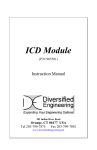
PIC17C75X Protoboard
Profile
• All-in-one hardware
prototyping and
development solution
for Microchip PIC17C75X PICmicro®
MCUs
• Designed for PIC17C75X's single-chip (microcontroller) and
multi-chip (extended microcontroller & microprocessor) modes
via on-board external ROM and RAM
Benefits
• Off-the-shelf design is versatile, portable and affordable
• Flexible external memory architecture extends PIC17C75X's
program and data memory spaces
• External Flash ROMs can be programmed with a standard
device programmer — no adapters necessary
• Up to 1MB of paged external RAM for buffers, file storage, etc.
• Works out-of-the-box with blank PIC17C75X devices
You
• Are quickly up and running
• Beat your competition to market
• Don't re-invent the wheel
Features
• For Microchip PIC17C752 and PIC17C756A PICmicro® MCUs
• Up to 128KB of external program memory (Flash, EPROM, etc.)1
• Up to 1MB of external RAM in 16KB (8Kword) pages2
• CPU can operate in microcontroller, extended microcontroller or
microprocessor mode with external ROM and/or RAM
• 0-33MHz, 3.0-5.5V operation3
• All-CMOS design with a socket for every chip
• Switch-selectable multiple power sources:
• 6-26Vdc4
• 9V battery
• Direct dc5
• Jumper-selectable oscillator or external crystal clock source
• Sockets for I2C, SPI and Microwire serial EEPROMs
• 2-channel RS-232 transceiver with DB-9 connectors6
• External reset supervisor and pushbutton switch
• Dual-row 0.100" headers for all CPU pins7
• 1.200" x 1.500" breadboard area
• ZIF sockets for Flash ROMs
• Test points for dc signals
• 8.00 x 4.00 x 1.50" (204 x 102 x 38mm) protoboard includes:
• Complete, tested unit8
• Test and verification code9
• Comprehensive user manual
————
1. The Harvard-architecture PIC17C75X family employs 16-bit-wide instruction words in a program memory space of up to 64K x 16 bits. The separate
data path is 8 bits wide. Data can be moved from the program memory space to the data memory space, and vice versa, via table reads and writes.
2. RAM paging circuitry (6 most significant address bits) uses PIC17C75X's RB7/SDO, RB6/SCK and RE3/CAP4 as SPI data, clock and strobe,
respectively. For use in extended microcontroller and microprocessor modes. Can be driven by MSSP Serial Peripheral Interface (SPI), or in software.
3. Supplied and tested with 5V CMOS components. Operation at other voltages is via direct dc power source, and may require alternate components.
®
4. Accepts 2.5mm plug (pin is hot). Compatible with Microchip PICSTART Plus power supply and others.
5. 6-26Vdc and 9V battery power sources are regulated down to 5Vdc. Direct dc power source bypasses regulator and feeds components directly,
enabling lower-voltage operation and accurate power consumption measurements.
6. Each male / plug connector is wired as DTE for software (XON/XOFF) handshaking via a null-modem cable to a PC or other DTE device.
7. Except AVss and TEST.
8. Includes two AT28F010 128Kx8 Flash ROMs, two 62256 32Kx8 CMOS RAMs and one 32Kx8 CMOS I2C Serial EEPROM. Does not include 17C75X
CPU, SPI or Microwire serial EEPROMs, or any external crystal oscillator components.
9. Flash ROMs are supplied pre-programmed with SalvoTM-based test and verification application.
Contact
750 Naples Street
San Francisco, CA 94112
tel: 415-584-6360
fax: 415-585-7948
web: www.pumpkininc.com
email: [email protected]
Specifications subject to change without notice.
© 2002 Pumpkin, Inc. All rights reserved. Pumpkin
and the Pumpkin logo, Salvo and the Salvo logo, and
The RTOS that runs in tiny places are trademarks of
Pumpkin, Inc. PICmicro and PICSTART are
registered trademarks of Microchip Corporation. All
other trademarks are the property of their respective
owners.
707-00202 Feb. 2002