1
User Manual
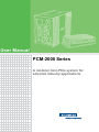
PCM-2000 Series
A modular mini-PCIe system for
selected industry applications
Copyright
The documentation and the software included with this product are copyrighted 2014
by Advantech Co., Ltd. All rights are reserved. Advantech Co., Ltd. reserves the right
to make improvements in the products described in this manual at any time without
notice. No part of this manual may be reproduced, copied, translated or transmitted
in any form or by any means without the prior written permission of Advantech Co.,
Ltd. Information provided in this manual is intended to be accurate and reliable. However, Advantech Co., Ltd. assumes no responsibility for its use, nor for any infringements of the rights of third parties, which may result from its use.
Acknowledgements
Intel and Pentium are trademarks of Intel Corporation.
Microsoft Windows and MS-DOS are registered trademarks of Microsoft Corp.
All other product names or trademarks are properties of their respective owners.
Product Warranty (5 years)
Advantech warrants to you, the original purchaser, that each of its products will be
free from defects in materials and workmanship for two years from the date of purchase.
This warranty does not apply to any products which have been repaired or altered by
persons other than repair personnel authorized by Advantech, or which have been
subject to misuse, abuse, accident or improper installation. Advantech assumes no
liability under the terms of this warranty as a consequence of such events.
Because of Advantech’s high quality-control standards and rigorous testing, most of
our customers never need to use our repair service. If an Advantech product is defective, it will be repaired or replaced at no charge during the warranty period. For outof-warranty repairs, you will be billed according to the cost of replacement materials,
service time and freight. Please consult your dealer for more details.
If you think you have a defective product, follow these steps:
1. Collect all the information about the problem encountered. (For example, CPU
speed, Advantech products used, other hardware and software used, etc.) Note
anything abnormal and list any onscreen messages you get when the problem
occurs.
2. Call your dealer and describe the problem. Please have your manual, product,
and any helpful information readily available.
3. If your product is diagnosed as defective, obtain an RMA (return merchandize
authorization) number from your dealer. This allows us to process your return
more quickly.
4. Carefully pack the defective product, a fully-completed Repair and Replacement
Order Card and a photocopy proof of purchase date (such as your sales receipt)
in a shippable container. A product returned without proof of the purchase date
is not eligible for warranty service.
5. Write the RMA number visibly on the outside of the package and ship it prepaid
to your dealer.
PCM Series User Manual
Part No. 2003P20000
Edition 1
Printed in Taiwan
May 2015
ii
Declaration of Conformity
CE
This product has passed the CE test for environmental specifications when shielded
cables are used for external wiring. We recommend the use of shielded cables. This
kind of cable is available from Advantech. Please contact your local supplier for
ordering information.
FCC Class A
Note: This equipment has been tested and found to comply with the limits for a Class
A digital device, pursuant to part 15 of the FCC Rules. These limits are designed to
provide reasonable protection against harmful interference when the equipment is
operated in a commercial environment. This equipment generates, uses, and can
radiate radio frequency energy and, if not installed and used in accordance with the
instruction manual, may cause harmful interference to radio communications. Operation of this equipment in a residential area is likely to cause harmful interference in
which case the user will be required to correct the interference at his own expense.
Technical Support and Assistance
1.
2.
Visit the Advantech web site at www.advantech.com/support where you can find
the latest information about the product.
Contact your distributor, sales representative, or Advantech's customer service
center for technical support if you need additional assistance. Please have the
following information ready before you call:
– Product name and serial number
– Description of your peripheral attachments
– Description of your software (operating system, version, application software,
etc.)
– A complete description of the problem
– The exact wording of any error messages
iii
PCM Series User Manual
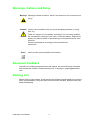
Warnings, Cations and Notes
Warning! Warnings indicate conditions, which if not observed, can cause personal
injury!
Caution! Cautions are included to help you avoid damaging hardware or losing
data. e.g.
There is a danger of a new battery exploding if it is incorrectly installed.
Do not attempt to recharge, force open, or heat the battery. Replace the
battery only with the same or equivalent type recommended by the manufacturer.
Discard used batteries according to the manufacturer's
instructions.
Note!
Notes provide optional additional information.
Document Feedback
To assist us in making improvements to this manual, we would welcome comments
and constructive criticism. Please send all such - in writing to: support@advantech.
com
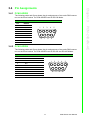
Packing List
Before setting up the system, check that the items listed in each chapter are included
and in good condition. If any item does not accord with the table, please contact your
dealer immediately.
PCM Series User Manual
iv
Safety Instructions
1.
2.
3.
Read these safety instructions carefully.
Keep this User Manual for later reference.
Disconnect this equipment from any AC outlet before cleaning. Use a damp
cloth. Do not use liquid or spray detergents for cleaning.
4. For plug-in equipment, the power outlet socket must be located near the equipment and must be easily accessible.
5. Keep this equipment away from humidity.
6. Put this equipment on a reliable surface during installation. Dropping it or letting
it fall may cause damage.
7. The openings on the enclosure are for air convection. Protect the equipment
from overheating. DO NOT COVER THE OPENINGS.
8. Make sure the voltage of the power source is correct before connecting the
equipment to the power outlet.
9. Position the power cord so that people cannot step on it. Do not place anything
over the power cord.
10. All cautions and warnings on the equipment should be noted.
11. If the equipment is not used for a long time, disconnect it from the power source
to avoid damage by transient overvoltage.
12. Never pour any liquid into an opening. This may cause fire or electrical shock.
13. Never open the equipment. For safety reasons, the equipment should be
opened only by qualified service personnel.
14. If one of the following situations arises, get the equipment checked by service
personnel:
15. The power cord or plug is damaged.
16. Liquid has penetrated into the equipment.
17. The equipment has been exposed to moisture.
18. The equipment does not work well, or you cannot get it to work according to the
user's manual.
19. The equipment has been dropped and damaged.
20. The equipment has obvious signs of breakage.
21. DO NOT LEAVE THIS EQUIPMENT IN AN ENVIRONMENT WHERE THE
STORAGE TEMPERATURE MAY GO BELOW -20° C (-4° F) OR ABOVE 60° C
(140° F). THIS COULD DAMAGE THE EQUIPMENT. THE EQUIPMENT
SHOULD BE IN A CONTROLLED ENVIRONMENT.
22. CAUTION: DANGER OF EXPLOSION IF BATTERY IS INCORRECTLY
REPLACED. REPLACE ONLY WITH THE SAME OR EQUIVALENT TYPE
RECOMMENDED BY THE MANUFACTURER, DISCARD USED BATTERIES
ACCORDING TO THE MANUFACTURER'S INSTRUCTIONS.
23. The sound pressure level at the operator's position according to IEC 704-1:1982
is no more than 70 dB (A).
DISCLAIMER: This set of instructions is given according to IEC 704-1. Advantech
disclaims all responsibility for the accuracy of any statements contained herein.
v
PCM Series User Manual
Safety Precaution - Static Electricity
Follow these simple precautions to protect yourself from harm and the products from
damage.
To avoid electrical shock, always disconnect the power from your PC chassis
before you work on it. Don't touch any components on the CPU card or other
cards while the PC is on.
Disconnect power before making any configuration changes. The sudden rush
of power as you connect a jumper or install a card may damage sensitive electronic components.
PCM Series User Manual
vi
Contents
Chapter
Chapter
Chapter
1
Introduction..........................................1
1.1
1.2
Description ................................................................................................ 2
PCM Support Summary ............................................................................ 2
2
PCM-2300MR-AE..................................3
2.1
2.2
2.3
Initial Inspection ........................................................................................ 4
Driver Setup & Installation- Advantech Device Manager Installation ........ 5
Format....................................................................................................... 7
2.3.1 Windows Format ........................................................................... 7
2.3.2 Advantech provides MRAM driver format ..................................... 8
3
PCM-24DxRx-AE ................................11
3.1
3.2
Initial Inspection ...................................................................................... 12
Jumper and Switch Settings.................................................................... 13
3.2.1 PCM-24D2R4 Settings............................................................... 13
Table 3.1: Master/Slave Settings............................................... 13
Table 3.2: Terminal Resistor Settings ....................................... 13
3.2.2 PCM-24D4R4 Settings................................................................ 14
Table 3.3: Master/Slave Settings............................................... 14
Table 3.4: Terminal Resistor Settings ....................................... 14
Driver Setup & Installation....................................................................... 15
3.3.1 Introduction ................................................................................. 15
3.3.2 Driver Setup ................................................................................ 15
3.3.3 Steps for Operating System Driver Setup................................... 15
3.3.4 Driver Uninstall............................................................................ 16
Pin Assignments ..................................................................................... 17
3.4.1 PCM-24D2R2.............................................................................. 17
Table 3.5: PCM-24D2R2 Male DB9 on iDoor bracket ............... 17
3.4.2 PCM-24D2R4.............................................................................. 17
Table 3.6: PCM-24D2R4 Male DB9 on iDoor Bracket............... 17
3.4.3 PCM-24D4R2.............................................................................. 18
Table 3.7: PCM-24D4R2 Male DB9 on Cable ........................... 18
Table 3.8: PCM-24D4R2 Female DB37 on iDoor bracket......... 18
3.4.4 PCM-24D4R4.............................................................................. 19
Table 3.9: PCM-24D4R4 Male DB9 on Cable ........................... 19
Table 3.10: PCM-24D4R4 Female DB37 on iDoor bracket......... 19
Wiring ...................................................................................................... 20
3.5.1 RS-232 Signal Wiring.................................................................. 20
Table 3.11: Terminal or PC (DTE) Connections.......................... 20
Table 3.12: Modem Connections................................................. 20
Table 3.13: Terminal without Handshake .................................... 21
3.5.2 RS-422 Signal Wiring.................................................................. 21
Table 3.14: RS-422 DB9 Pin Assignment ................................... 21
3.5.3 RS-485 Signal Wiring.................................................................. 22
Figure 3.1 RS-485 Wiring Topology .......................................... 22
3.3
3.4
3.5
Chapter
4
PCM-26D2CA......................................23
4.1
4.2
Initial Inspection ...................................................................................... 24
Driver and Advantech Device Manager Installation ................................ 25
vii
PCM Series User Manual
4.3
4.4
4.5
Chapter
Chapter
Chapter
Chapter
Jumper and Switch Settings ................................................................... 27
Figure 4.1 CAN-bus transceiver board silk screen .................... 27
4.3.1 How to Set Jumpers ................................................................... 27
Figure 4.2 How to set the jumpers............................................. 27
4.3.2 Terminator Resistor Setup (JP1) ................................................ 27
Table 4.1: PCM-26D2CA Terminator Resistor Jumper Setting. 27
Pin Assignments ..................................................................................... 28
Figure 4.3 PCM-26D2CA DB-9 connector pin assignments...... 28
Figure 4.4 PCM-26D2CA DB-9 connector schematics.............. 28
Table 4.2: PCM-26D2CA Pin Description ................................. 28
Wiring...................................................................................................... 29
Figure 4.5 FPC cable wiring ...................................................... 29
Figure 4.6 Wiring on module side.............................................. 29
5
PCM-23U1DG-AE............................... 31
5.1
5.2
5.3
Initial Inspection ...................................................................................... 32
Driver Setup & Installation- Advantech Device Manager Installation...... 32
Pin Assignment and Wiring..................................................................... 33
5.3.1 Pin Assignment........................................................................... 33
5.3.2 Wiring.......................................................................................... 33
6
PCM-2300TP-AE ................................ 35
6.1
6.2
6.3
Initial Inspection ...................................................................................... 36
Driver Setup & Installation- Advantech Device Manager Installation...... 36
Pin Assignment and Wiring..................................................................... 36
7
PCM-23C1CF-AE ............................... 37
7.1
7.2
7.3
Initial Inspection ...................................................................................... 38
Driver Setup & Installation- Advantech Device Manager Installation...... 38
Pin Assignment and Wiring..................................................................... 39
7.3.1 Pin Assignment........................................................................... 39
7.3.2 Wiring.......................................................................................... 40
8
PCM-24R1TP-AE ............................... 41
8.1
8.2
Initial Inspection ...................................................................................... 42
Driver Setup & Installation- Advantech Device Manager Installation...... 43
8.2.1 Introduction ................................................................................. 43
8.2.2 Installation................................................................................... 43
Pin Assignment and Wiring..................................................................... 46
8.3.1 Pin Assignment........................................................................... 46
8.3.2 Wiring.......................................................................................... 47
8.3
Chapter
9
PCM-24R2PE-AE ............................... 49
Chapter
9
PCM-24R2GL-AE ............................... 49
9.1
9.2
Initial Inspection ...................................................................................... 50
Driver Setup & Installation- Advantech Device Manager Installation...... 51
9.2.1 Introduction ................................................................................. 51
9.2.2 Installation................................................................................... 51
PCM Series User Manual
viii
9.3
9.2.3 Uninstall ...................................................................................... 54
Pin Assignment and Wiring ..................................................................... 56
9.3.1 Pin Assignment ........................................................................... 56
9.3.2 Wiring.......................................................................................... 57
Chapter 10
PCM-24U2U3 ......................................59
10.1
10.2
Initial Inspection ...................................................................................... 60
Driver Setup & Installation- Advantech Device Manager Installation ...... 61
10.2.1 Introduction ................................................................................. 61
10.2.2 Installation................................................................................... 61
10.2.3 Uninstall ...................................................................................... 63
Pin Assignment and Wiring ..................................................................... 64
10.3.1 Pin Assignment ........................................................................... 64
10.3.2 Wiring.......................................................................................... 64
10.3
Appendix A
PCM-2300MR-AE................................67
A.1
A.2
Initial Inspection ...................................................................................... 68
Diagnostic LEDs...................................................................................... 70
Table A.1: Diagnostic LED Definitions ....................................... 70
ix
PCM Series User Manual
PCM Series User Manual
x
Chapter
1
1
Introduction
This chapter provides a general
description of the PCM modules
description and support summary.
Sections include:
Description
PCM Support Summary
1.1 Description
Advantech designed iDoor technology by support for the flexible optional connector
arrangement for the Advantech embedded Automation computing platform including
connector, internal cabling and a wide range of I/O and communication Modules.
Supporting:
Optional WLAN and GPRS modules including Antenna, RT Ethernet and serial
Fieldbus options
Non-volatile Memory options
Optical isolated Serial Ports RS232/422/485
LAN ports supporting IEEE-1588 PTP
I/O extension modules
Wireless IO communication
1.2 PCM Support Summary
Model
Manual
Drivers
Datasheet
Startup
PCM-2300MR-AE
Chapter 2
Refer to DVD
Refer to DVD
Refer to DVD
PCM-24D2R4-AE
Chapter 3
Refer to DVD
Refer to DVD
Refer to DVD
PCM-24D2R2-AE
Chapter 3
Refer to DVD
Refer to DVD
Refer to DVD
PCM-24D4R4-AE
Chapter 3
Refer to DVD
Refer to DVD
Refer to DVD
PCM-24D4R2-AE
Chapter 3
Refer to DVD
Refer to DVD
Refer to DVD
PCM-26D2CA-AE
Chapter 4
Refer to DVD
Refer to DVD
Refer to DVD
PCM-26D1PB-AE
Refer to DVD
From Hilscher Refer to DVD
Refer to DVD
PCM‐23U1DG‐AE
PCM‐2300TP‐AE
Chapter 5
Refer to DVD
Refer to DVD
Chapter 6
Refer to Advantech PCA-TPM-00A1E product
information for Driver, Datasheet, Manual and
Startup
PCM‐23C1CF‐AE
PCM‐24R1TP‐AE
Chapter 7
Refer to DVD
Refer to DVD
Refer to DVD
Chapter 8
Refer to DVD
Refer to DVD
Refer to DVD
PCM‐24R2PE‐AE
PCM‐24R2GL‐AE
Chapter 9
Refer to DVD
Refer to DVD
Refer to DVD
PCM Series User Manual
2
Refer to DVD
Chapter
2
2
PCM-2300MR-AE
2MB MRAM mini-PCIe card
This chapter shows how to install
the driver and Advantech Device
Manager.
Sections include:
Initial Inspection
Driver Setup & InstallationAdvantech Device Manager
Installation
Format
2.1 Initial Inspection
You should find the following items inside the package:
Mini-PCIe communication interface card
Industrial Communication Driver, Utility and mini-PCIe communication card
user's manual in PCM-2000 DVD-ROM
The PCM-2300MR was carefully inspected mechanically and electrically before it
was shipped. It should be free of marks and scratches and in perfect working order
when received.
As you unpack the PCM-2300MR, check for signs of shipping damage (damaged
box, scratches, dents, etc.). If it is damaged or it fails to meet specifications, notify
our service department or your local sales representative immediately. Also notify the
carrier. Retain the shipping carton and packing material for inspection by the carrier.
After inspection we will make arrangements to repair or replace the unit.
When you handle the PCM-2300MR, remove it from its protective packaging by
grasping the rear metal panel. Keep the anti-vibration packing. Whenever you
remove the card from the PC, store it in this package for protection.
Warning! Discharge your body's static electric charge by touching the back of the
grounded chassis of the system unit (metal) before handling the board.
You should avoid contact with materials that hold a static charge such
as plastic, vinyl and Styrofoam. Handle the board only by its edges to
avoid static damage to its integrated circuits. Avoid touching the
exposed circuit connectors. We also recommend that you use a
grounded wrist strap and place the card on a static dissipative mat
whenever you work with it.
PCM Series User Manual
4
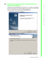
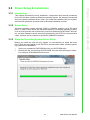
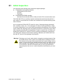
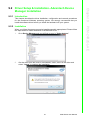
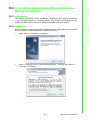
Advantech provides WDM MRAM driver that allows you to configure your hardware
and store the settings in your Windows registry. You must install the WDM MRAM
driver if you want to add and manage Advantech MRAM cards.
Follow the steps below to install Advantech MRAM WDM Driver.
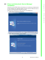
1. Select “Next” to continue the installation.
Chapter 2
2.2 Driver Setup & Installation- Advantech Device
Manager Installation
PCM-2300MR-AE
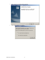
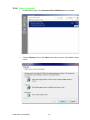
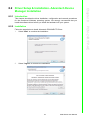
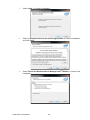
2.
Select “Install” to continue the installation.
5
PCM Series User Manual
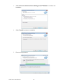
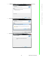
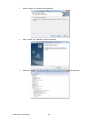
3.
After a while, the installation will be complete.
4.
Select OK to Restart your computer.
PCM Series User Manual
6
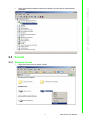
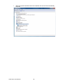
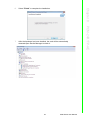
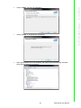
After the physical hardware has been installed, the card will be automatically
detected.
Chapter 2
5.
PCM-2300MR-AE
2.3 Format
2.3.1 Windows Format
1.
Right click the mouse to select “format”
7
PCM Series User Manual
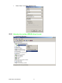
2.
Select “Start” to complete MRAM format.
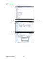
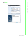
2.3.2 Advantech provides MRAM driver format
1.
Use Device Manager….
PCM Series User Manual
8
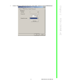
Select “Settings” page and then click “Clear data” button to format MRAM disk.
Chapter 2
2.
PCM-2300MR-AE
9
PCM Series User Manual
PCM Series User Manual
10
Chapter
3
3
PCM-24DxRx-AE
PCM-24D2R4-AE, PCM-24D2R2AE, PCM-24D4R4-AE, PCM24D4R2-AE
Industrial Serial Communication
Cards
This chapter covers inspection
and installation of hardware and
drivers.
Sections include:
Ordering Information
Initial Inspection
Jumper and Switch Settings
Driver Setup & Installation
Pin Assignment
Wiring
Ordering information:
Product
Description
PCM-24D2R2-AE
2-Ports Isolated RS-232 mini-PCIe, DB9
PCM-24D2R4-AE
2-Ports Isolated RS-422/485 mini-PCIe, DB9
PCM-24D4R2-AE
4-Ports Non-Isolated RS-232 mini-PCIe, DB37
PCM-24D4R4-AE
4-Ports Non-Isolated RS-422/485 mini-PCIe, DB37
3.1 Initial Inspection
1.
PCM-2400 Communication card including:
A.
PCM-2400 mini-PCIe Card
B.
I/O plate.
C.
Wire cable
D.
DB37 to DB9(4 ports) cable (For PCM-24D4R4-AE only)
2. PCM-2000 DVD-ROM including:
A.
User manual
B.
Industrial Communication Driver
We carefully inspect our PCM-2400 communication card mechanically and electrically before shipping. It should be free of marks and scratches and in perfect working
condition on receipt.
As you unpack, check for any signs of shipping damage (damaged box, scratches,
dents, etc.). Should any damage is found or it fail to meet specifications, please notify
our service department or your local sales representative immediately. Also the carrier should be notified. Retain the shipping carton and packing material for further
inspections by the carrier.
After inspection we will make arrangements to repair or replace the unit.
When you handle the communication card, remove it from its protective packaging by
grasping the rear metal panel. Keep the anti-vibration packaging for further storage,
as the card was removed from the PC.
Warning! Discharge your body’s static electric charge by touching the back of the
grounded chassis of the system unit (metal) before handling the board.
You should avoid contact with materials that hold a static charge such
as plastic, vinyl and Styrofoam. Handle the board only by its edges to
avoid static damage to its integrated circuits. Avoid touching the
exposed circuit connectors. We also recommend that you use a
grounded wrist strap and place the card on a static dissipative mat
whenever you work with it.
PCM Series User Manual
12
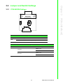
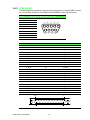
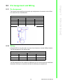
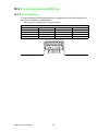
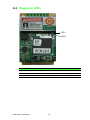
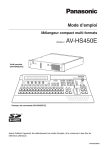
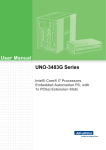
CN3
PCM-24D2R4 Settings
CN2
PCM-24DxRx-AE
SW1
CN1
3.2.1
Chapter 3
3.2 Jumper and Switch Settings
Table 3.1: Master/Slave Settings
Jumper
CN2
Pin
Description
1-2
RS-422 Master
2-3
RS-485/RS-422 Slave (Default)
Table 3.2: Terminal Resistor Settings
Switch
Terminal Resistor
Switch Setting
120 ohm
1(D+/-) on
2(RX+/-) on
SW1
3,4 off
3(D+/-) on
4(RX+/-) on
300 ohm
1,2 off
13
PCM Series User Manual
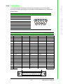
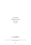
SW2
SW1
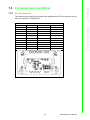
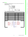
3.2.2 PCM-24D4R4 Settings
SW3
CN2
CN1
Table 3.3: Master/Slave Settings
COM Port
Switch
Pin
COM 1
1
COM 2
2
SW1
COM 3
3
COM 4
4
Setting
Description
ON
RS-422 Master
OFF
RS-485/RS-422 Slave (Default)
ON
RS-422 Master
OFF
RS-485/RS-422 Slave (Default)
ON
RS-422 Master
OFF
RS-485/RS-422 Slave (Default)
ON
RS-422 Master
OFF
RS-485/RS-422 Slave (Default)
Table 3.4: Terminal Resistor Settings
COM Port Switch
Pin
1
COM 1
2
SW2
3
COM 2
4
1
COM 3
2
SW3
3
COM 4
4
PCM Series User Manual
Setting
RS-422 Description RS-485 Description
ON
120 Ohm between
Tx+/Tx-
OFF
Open (Default)
ON
120 Ohm between
Rx+/Rx-
OFF
Open (Default)
ON
120 Ohm between
Tx+/Tx-
OFF
Open (Default)
ON
120 Ohm between
Rx+/Rx-
OFF
Open (Default)
ON
120 Ohm between
Tx+/Tx-
OFF
Open (Default)
ON
120 Ohm between
Rx+/Rx-
OFF
Open (Default)
ON
120 Ohm between
Tx+/Tx-
OFF
Open (Default)
ON
120 Ohm between
Rx+/Rx-
OFF
Open (Default)
14
120 Ohm between
Data+/DataInvalid
120 Ohm between
Data+/DataInvalid
120 Ohm between
Data+/DataInvalid
120 Ohm between
Data+/DataInvalid
3.3.1 Introduction
This chapter describes the driver installation, configuration and removal procedures
for the for the afore mentioned Windows operating system. We strongly recommend
that you install the software driver before you install the hardware into your system,
since this will guarantee a smooth and trouble-free installation process.
Windows operating system supports COM1 to COM256, meaning up to 256 serial
ports. In order to fully utilize the advanced features of Windows operating system,
such as multi-process and multi-thread, pure 32-bit Windows 2K/XP/Vista/7 and others, as afore indicated, device drivers are provided for the PCI/PCIe communication
cards. All these drivers conform to the Win32 COMM API standard.
3.3.3 Steps for Operating System Driver Setup
Before you install the card into your system, we recommend you install the driver
first. Follow the steps below for the PCI/PCIe communication cards' windows operating system driver installation.
1. Insert your companion DVD-ROM disc into your DVD-ROM drive.
2. Double click the .exe file from the DVD-ROM, then the driver will begin to setup.
For example, PCM-24DxRx\Driver\xx.exe.
15
PCM Series User Manual
PCM-24DxRx-AE
3.3.2 Driver Setup
Chapter 3
3.3 Driver Setup & Installation
3.3.4 Driver Uninstall
1.
In the Control Panel, click Advantech PCI ICOM Driver then uninstall.
2.
Choose "Remove" then click "Next" then start to remove all installed components.
PCM Series User Manual
16
3.4.1 PCM-24D2R2
The following table and figure shows the pin assignments of two male DB9 connectors on the iDoor bracket for PCM-24D2R2 card in RS-232 Mode.
Table 3.5: PCM-24D2R2 Male DB9 on iDoor bracket
RS-232
1
DCD
2
RxD
3
TxD
4
DTR
5
GND
6
DSR
7
RTS
8
CTS
9
RI
1
2
6
3
7
4
8
5
9
3.4.2 PCM-24D2R4
The following table and figure shows the pin assignments of two male DB9 connectors on the iDoor bracket for PCM-24D2R4 card in RS-422 and RS-485 Modes.
Table 3.6: PCM-24D2R4 Male DB9 on iDoor Bracket
Pin
RS-422
RS-485
1
Tx-
Data-
2
Tx+
Data+
3
Rx+
-
4
Rx-
-
5
GND
GND
6
RTS-
-
7
RTS+
-
8
CTS+
-
9
CTS-
-
1
2
6
17
3
7
4
8
5
9
PCM Series User Manual
PCM-24DxRx-AE
Pin
Chapter 3
3.4 Pin Assignments
3.4.3 PCM-24D4R2
The following tables and figures show the pin assignments of 1 female DB37 connector one the iDoor bracket to male DB9 for PCM-24D4R2 card in RS-232 mode.
Table 3.7: PCM-24D4R2 Male DB9 on Cable
Pin
RS-232
1
DCD
2
RxD
3
TxD
4
DTR
5
GND
6
DSR
7
RTS
8
CTS
9
RI
1
2
6
3
7
4
8
5
9
Table 3.8: PCM-24D4R2 Female DB37 on iDoor bracket
Pin
RS-232
Pin
RS-232
1
-
20
3_RI
2
3_DCD
21
3_DTR
3
3_GND
22
3_DSR
4
3_CTS
23
3_RTS
5
3_RxD
24
3_TxD
6
4_RI
25
4_DCD
7
4_DTR
26
4_GND
8
4_DSR
27
4_CTS
9
4_RTS
28
4_RxD
10
4_TxD
29
2_RI
11
2_DCD
30
2_DTR
12
2_GND
31
2_DSR
13
2_CTS
32
2_RTS
14
2_RxD
33
2_TxD
15
1_RI
34
1_DCD
16
1_DTR
35
1_GND
17
1_DTS
36
1_CTS
18
1_RTS
37
1_RxD
19
1_TxD
1
19
37
PCM Series User Manual
20
18
The following tables and figures show the pin assignments of 1 female DB37 connector one the iDoor bracket to male DB9 for PCM‐24D4R4 card in RS‐422 and RS‐485 modes.
Table 3.9: PCM-24D4R4 Male DB9 on Cable
RS-422
RS-485
1
Tx-
Data-
2
Tx+
Data+
3
Rx+
-
4
Rx-
-
5
GND
GND
6
-
7
-
8
-
9
-
1
2
6
3
7
4
8
5
9
Table 3.10: PCM-24D4R4 Female DB37 on iDoor bracket
Pin
RS-422
RS-485
Pin
RS-422
RS-485
1
-
-
20
-
-
2
3_TxD-
3_Data-
21
3_RxD-
-
3
3_GND
3_GND
22
-
-
4
-
-
23
-
-
5
3_TxD+
3_Data+
24
3_RxD+
-
6
-
-
25
4_TxD-
4_Data-
7
4_RxD-
-
26
4_GND
4_GND
8
-
-
27
-
-
9
-
-
28
4_TxD+
4_Data+
10
4_RxD+
29
-
-
11
2_TxD-
2_Data-
30
2_RxD-
-
12
2_GND
2_GND
31
-
-
13
-
-
32
-
-
14
2_TxD+
2_Data+
33
2_RxD+
-
15
-
-
34
1_TxD-
1_Data-
16
1_RxD-
-
35
1_GND
1_GND
17
-
-
36
-
-
18
-
-
37
1_TxD+
1_Data+
19
1_RxD+
-
1
19
37
20
19
PCM Series User Manual
PCM-24DxRx-AE
Pin
Chapter 3
3.4.4 PCM-24D4R4
3.5 Wiring
3.5.1 RS-232 Signal Wiring
Since the RS-232 interface is not strictly defined, many devices have their own connection methods which may ignore some signal lines or define reserved lines for
other functions. It is best to refer to the user’s manual for your device for installation
instructions. You may find the following helpful.
In general, DTE (Data Terminal Equipment) refers to the device that is leading the
communication. Examples include PC’s, terminals and some printers. DCE refers to
the device being communicated with or controlled. Examples include modems,
DSU’s (digital service units), printers and lab/factory equipment.
In some situations you may be able to get by with just three lines: data on TXD, a signal ground and a handshaking line. Examples are printer or plotter connections, troubleshooting and situations where you require only one-wire communication.
Table 3.11: Terminal or PC (DTE) Connections
DB-25 Male
DB-25 Male or Female: Terminal
Pin
Signal
Pin
Signal
2
TxD
3
RxD
3
RxD
2
TxD
4
RTS
5
CTS
5
CTS
4
RTS
6
DSR
20
DTR
7
GND
7
GND
20
DTR
6
DSR
8
DCD
8
DCD
Table 3.12: Modem Connections
DB-25 Male
Modem (DCE)
Pin
Signal
Pin
Signal
2
TxD
3
RxD
3
RxD
2
TxD
4
RTS
5
CTS
5
CTS
4
RTS
6
DSR
20
DTR
7
GND
7
GND
20
DTR
6
DSR
8
DCD
8
DCD
PCM Series User Manual
20
Table 3.13: Terminal without Handshake
DB-25 Male
Terminal, PC (DTE)
Signal
Pin
Signal
2
TxD
3
RxD
3
RxD
2
TxD
4
RTS
5
CTS
7
GND
7
GND
6
DSR
20
DTR
8
DCD
Therefore, if you are not using CTS, RTS, DSR,DTR and DCD signals, short pins 4
and 5 together, and please short pins 6, 8,and 20 together.
3.5.2 RS-422 Signal Wiring
The RS-422 interface wiring is based on one-to-one principles. The transmit lines on
one side connect to the receive lines on the other side, and vice versa. With RS-422,
you can transmit and receive data simultaneously (full duplex). The connections are
as follows:
Table 3.14: RS-422 DB9 Pin Assignment
DTE (Male DB-9)
Terminal DTE
Pin
Signal
Pin
Signal
1
TxD-
1
RxD-
2
TxD+
2
RxD+
3
RxD+
3
TxD+
4
RxD-
4
TxD-
5
GND
5
GND
6
RTS-
6
CTS-
7
RTS+
7
CTS+
8
CTS+
8
RTS+
9
CTS-
9
RTS-
Terminator Resistors Setup
The signals DSR, DTR and DCD are shorted internally on the PCM-24D2R4/24D4R4
cards when operating in RS-422 mode.
A user can solder in termination resistors if necessary for impedance matching. The
card has two mounting spaces for termination resistors, but no resistors are installed
at the factory. Each pair of signal lines has a separate resistor (RxD+/-, TxD+/-).
21
PCM Series User Manual
PCM-24DxRx-AE
Pin
Chapter 3
For DTE to DCE connections, use a straight through cable (i.e., you don't have to
reverse lines 2 and 3, lines 4 and 5, and lines 6 and 20 since, in general, the DCE
RS-232 interfaces are reversed themselves).
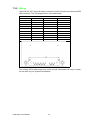
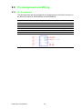
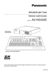
3.5.3 RS-485 Signal Wiring
The RS-485 standard supports half-duplex communication. This means that just two
wires are needed to both transmit and receive data. Handshaking signals (such as
RTS, Request To Send) are normally used to control the direction of the data flow
and to switch the transmission accordingly. In RS-485 mode, the PCM-24D2R4/
24D4R4 cards automatically sense the direction of the data flow and switch the transmission direction — no handshaking is necessary. This means a user can build an
RS-485 network with just two wires. This RS-485 control is completely transparent to
the user. The software written for half duplex RS-232 works without any modification.
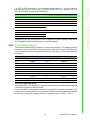
D.T.E
RS-485
Transceiver
D.T.E
RS-485
Transceiver
Data+
Data+
Data-
120
Ohm
Data-
D.T.E
RS-485
Transceiver
Data+
Data-
120
Ohm
Figure 3.1 RS-485 Wiring Topology
Termination Resistor Setup
You can install termination resistors if necessary for impedance matching. The card
has mounting spaces for termination resistors, but no resistors are installed at the
factory. Depending on your application you may need to solder in a single resistor to
handle the DATA+/DATA- pair (and a corresponding resistor on the other end of
the connection). The value of the resistor should equal the characteristic impedance
of the signal wires (approximately 120 Ohms or 300 Ohms).
PCM Series User Manual
22
Chapter
4
4
PCM-26D2CA
2-Ports Isolated CANBus miniPCIe, CANOpen, DB9
This chapter covers the pin
assignment for the CAN connector, and the wiring of the two
transmission wires.
Sections include:
Initial Inspection
Driver and Advantech Device
Manager Installation
Jumper and Switch Settings
Pin Assignment
Wiring
4.1 Initial Inspection
You should find the following items inside the shipping package:
Mini-PCIe communication interface card
Industrial Communication Driver, Utility and mini-PCIe communication card
user's manual in PCM-2000 DVD-ROM
PCM-26D2CA was carefully inspected mechanically and electrically before it was
shipped. It should be free of marks and scratches and in perfect working order when
received.
As you unpack the PCM Module, check for signs of shipping damage (damaged box,
scratches, dents, etc.). If it is damaged or it fails to meet specifications, notify our service department or your local sales representative immediately. Also notify the carrier.
Retain the shipping carton and packing material for inspection by the carrier.
After inspection we will make arrangements to repair or replace the unit.
When you handle the PCM Module, remove it from its protective packaging by grasping the rear metal panel. Keep the anti-vibration packing. Whenever you remove the
card from the PC, store it in this package for protection.
Warning! Discharge your body’s static electric charge by touching the back of the
grounded chassis of the system unit (metal) before handling the board.
You should avoid contact with materials that hold a static charge such
as plastic, vinyl and Styrofoam. Handle the board only by its edges to
avoid static damage to its integrated circuits. Avoid touching the
exposed circuit connectors. We also recommend that you use a
grounded wrist strap and place the card on a static dissipative mat
whenever you work with it.
PCM Series User Manual
24
Advantech provides WDM CAN driver that allows you to configure your hardware and
store the settings in your Windows registry. You must install the WDM CAN driver if
you want to add and manage Advantech CAN cards.
Please follow the steps below to install Advantech CAN WDM Driver.
1. Select “Next” to continue the installation.
Chapter 4
4.2 Driver and Advantech Device Manager
Installation
PCM-26D2CA
2.
After a while, the installation will be complete.
25
PCM Series User Manual
3.
After the physical hardware has been installed, the card will be automatically
detected.
PCM Series User Manual
26
Chapter 4
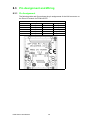
4.3 Jumper and Switch Settings
4.3.1 How to Set Jumpers
You configure your card to match the needs of your application by setting jumpers. A
jumper is the simplest kind of electric switch. It consists of two metal pins and a small
metal clip (often protected by a plastic cover) that slides over the pins to connect
them. To “close” a jumper you connect the pins with the clip. To “open” a jumper you
remove the clip.
Figure 4.2 How to set the jumpers
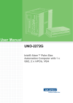
4.3.2 Terminator Resistor Setup (JP1)
You can set the terminator resistor if necessary to match impedance. Each port has a
separate resistor located on its own transceiver board.
Table 4.1: PCM-26D2CA Terminator Resistor Jumper Setting
Status
Value of Terminator Resistor (Ohm)
Pin 2-3
Open mode
None
Pin 1-2
Close mode
120 Ohms
Note!
is suggested to set the terminator resistor to 120 Ohm to maintain a satisfactory baud rate performance.
27
PCM Series User Manual
PCM-26D2CA
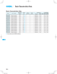
Figure 4.1 CAN-bus transceiver board silk screen
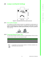
4.4 Pin Assignments
Figure 4.3 shows the pin assignment for the card’s male DB-9 connectors and corresponding pin assignments of female DB-9 connectors of the cable.
Figure 4.3 PCM-26D2CA DB-9 connector pin assignments
Figure 4.4 PCM-26D2CA DB-9 connector schematics
The CAN standard supports half–duplex communication. This means that just two
wires are used to transmit and receive data.
Table 4.2: PCM-26D2CA Pin Description
Pin
Signal
Description
2
CAN_L
LOW-level CAN voltage input/output
3
GND
Ground
7
CAN_H
HIGH-level CAN voltage input/output
PCM Series User Manual
28
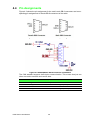
CAN-bus main board has two FPC connectors for wiring to two CAN-bus transceiver
boards through FPC cables. Please ensure to follow Figure 4.5 and Figure 4.6 for
appropriate wiring in between.
PCM-26D2CA
Figure 4.5 FPC cable wiring
Figure 4.6 Wiring on module side
29
Chapter 4
4.5 Wiring
PCM Series User Manual
PCM Series User Manual
30
Chapter
5
5
PCM-23U1DG-AE
USB Slot w/ Lock for USB Dongle
Sections include:
Initial Inspection
Driver Setup and Installation
Pin Assignment
Wiring
5.1 Initial Inspection
You should find the following items inside the shipped package:
PCM-2300 Storage Module:
– I/O plate.
– Wire cable
PCM-2000 DVD-ROM including:
– A. Industrial Communication Driver, Utility and mini-PCIe communication
card
The PCM-23U1DG was carefully inspected mechanically and electrically before it
was shipped. It should be free of marks and scratches and in perfect working order
when received.
As you unpack the PCM-23U1DG, check for signs of shipping damage (damaged
box, scratches, dents, etc.). If it is damaged or it fails to meet specifications, notify
our service department or your local sales representative immediately. Also notify the
carrier. Retain the shipping carton and packing material for inspection by the carrier.
After inspection we will make arrangements to repair or replace the unit. When you
handle the PCM-23U1DG, remove it from its protective packaging by grasping the
rear metal panel. Keep the anti-vibration packing. Whenever you remove the card
from the PC, store it in this package for protection.
Warning! Discharge your body’s static electric charge by touching the back of the
grounded chassis of the system unit (metal) before handling the board.
You should avoid contact with materials that hold a static charge such as
plastic, vinyl and Styrofoam. Handle the board only by its edges to avoid
static damage to its integrated circuits. Avoid touching the exposed circuit connectors. We also recommend that you use a grounded wrist
strap and place the card on a static dissipative mat whenever you work
with it.
5.2 Driver Setup & Installation- Advantech Device
Manager Installation
The Advantech PCM-23U1DG is an internal USB with locked interface for security
dongle disk or storage. The driver is based on the storage and there is no need for a
driver on the PCM-23U1DG.
PCM Series User Manual
32
5.3.1 Pin Assignment
The following table and figure shows the pin assignments of connector on the iDoor
I/O module for the PCM-23U1DG.
Chapter 5
5.3 Pin Assignment and Wiring
Cable PIN assignment
CN2, Internal cable for USB
5V
PIN1
5V
PIN2
D-
PIN2
D-
PIN3
D+
PIN3
D+
PIN4
GND
PIN4
GND
PIN5
GND_IO
5.3.2 Wiring
PCM-23U1DG is using flat cable to connect from IO plate to internal USB pin-header.
The PIN assignment in the below table
Cable PIN assignment
CN2, Internal cable for USB
Cable head for the system PIN header
PIN1
5V
PIN2
5V
PIN2
D-
PIN4
D-
PIN3
D+
PIN6
D+
PIN4
GND
PIN8
GND
The PIN assignment of the cable may different from the current system pin definition.
Advantech can help to customize the cable for different pin assignments.
33
PCM Series User Manual
PCM-23U1DG-AE
CN1, USB w/locked
PIN1
PCM Series User Manual
34
Chapter
6
6
PCM-2300TP-AE
Sections include:
Initial Inspection
Driver Setup and Installation
Pin Assignment
Wiring
6.1 Initial Inspection
You should find the following items inside the shipped package:
PCM-2300 Storage Module:
– I/O plate.
– Wire cable
PCM-2000 DVD-ROM including:
– Industrial Communication Driver, Utility and mini-PCIe communication card
The PCM-2300TP was carefully inspected mechanically and electrically before it was
shipped. It should be free of marks and scratches and in perfect working order when
received.
As you unpack the PCM-2300TP, check for signs of shipping damage (damaged box,
scratches, dents, etc.). If it is damaged or it fails to meet specifications, notify our
service department or your local sales representative immediately. Also notify the
carrier. Retain the shipping carton and packing material for inspection by the carrier.
After inspection we will make arrangements to repair or replace the unit. When you
handle the PCM-2300TP, remove it from its protective packaging by grasping the rear
metal panel. Keep the anti-vibration packing. Whenever you remove the card from
the PC, store it in this package for protection.
Warning! Discharge your body’s static electric charge by touching the back of the
grounded chassis of the system unit (metal) before handling the board.
You should avoid contact with materials that hold a static charge such as
plastic, vinyl and Styrofoam. Handle the board only by its edges to avoid
static damage to its integrated circuits. Avoid touching the exposed circuit connectors. We also recommend that you use a grounded wrist
strap and place the card on a static dissipative mat whenever you work
with it.
6.2 Driver Setup & Installation- Advantech Device
Manager Installation
For details about Advantech’s PCM-2300TP Driver Setup and Device Manager
Installation, refer to Advantech PCA-TPM-00A1E product information on the DVD.
6.3 Pin Assignment and Wiring
For details about Advantech’s PCM-2300TP Pin Assignment and Wiring, please refer
to the user manual from Advantech PCA-TPM-00A1E product information
The PIN assignment of the cable may different from the current system pin definition.
Advantech can help to customize the cable for different pin assignments.
PCM Series User Manual
36
Chapter
7
7
PCM-23C1CF-AE
SATAII to CFast
Sections include:
Initial Inspection
Driver Setup and Installation
Pin Assignment
Wiring
7.1 Initial Inspection
You should find the following items inside the shipped package:
PCM-2300 Storage Module:
– I/O plate.
PCM-2000 DVD-ROM including:
– A. Industrial Communication Driver, Utility and mini-PCIe communication
card
The PCM-23C1CF was carefully inspected mechanically and electrically before it
was shipped. It should be free of marks and scratches and in perfect working order
when received.
As you unpack the PCM-23C1CF, check for signs of shipping damage (damaged
box, scratches, dents, etc.). If it is damaged or it fails to meet specifications, notify
our service department or your local sales representative immediately. Also notify the
carrier. Retain the shipping carton and packing material for inspection by the carrier.
After inspection we will make arrangements to repair or replace the unit. When you
handle the PCM-23C1CF, remove it from its protective packaging by grasping the
rear metal panel. Keep the anti-vibration packing. Whenever you remove the card
from the PC, store it in this package for protection.
Warning! Discharge your body’s static electric charge by touching the back of the
grounded chassis of the system unit (metal) before handling the board.
You should avoid contact with materials that hold a static charge such as
plastic, vinyl and Styrofoam. Handle the board only by its edges to avoid
static damage to its integrated circuits. Avoid touching the exposed circuit connectors. We also recommend that you use a grounded wrist
strap and place the card on a static dissipative mat whenever you work
with it.
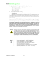
7.2 Driver Setup & Installation- Advantech Device
Manager Installation
Advantech’s PCM-23C1CF is a SATAII 3G/Sec to CFast interface for storage. The
driver is on the storage device and no need driver is required.
PCM Series User Manual
38
7.3.1 Pin Assignment
The following table and figure shows the pin assignments of CFast connector on the
iDoor IO module for PCM-23C1CF.
Chapter 7
7.3 Pin Assignment and Wiring
Description of PIN Use - CN2, CFast Connector
GND
PINPC6
NC
PINS2
SATA_TX+
PINPC7
GND
PINS3
SATA_TX-
PINPC8
NC
PINS4
GND
PINPC9
NC
PINS5
SATA_RX-
PINPC10
NC
PINS6
SATA_RX+
PINPC11
NC
PINS7
GND
PINPC12
NC
PINPC1
NC
PINPC13
3.3V
PINPC2
GND
PINPC14
3.3V
PINPC3
NC
PINPC15
GND
PINPC4
NC
PINPC16
GND
PINPC5
NC
PINPC17
NC
39
PCM-23C1CF-AE
PINS1
PCM Series User Manual
7.3.2 Wiring
The PCM-23C1CF uses a flat cable to connect from the I/O plate to the internal SATA
HDD connector. The PIN assignment is in the below table.
Description of PIN Use- CN1
PINS1
GND
PINP5
GND
PINS2
SATA_TX+
PINP6
GND
PINS3
SATA_TX-
PINP7
5V
PINS4
GND
PINP8
5V
PINS5
SATA_RX-
PINP9
5V
PINS6
SATA_RX+
PINP10
GND
PINS7
GND
PINP11
NC
PINP1
3.3V
PINP12
GND
PINP2
3.3V
PINP13
NC
PINP3
3.3V
PINP14
NC
PINP4
GND
PINP15
NC
The existing SATA cable length may not be enough. Advantech can help to customize the cable for your system requirements.
PCM Series User Manual
40
Chapter
8
8
PCM-24R1TP-AE
1 port Giga LAN mPCIe, RJ45
Sections include:
Initial Inspection
Driver and Advantech Device
Manager Installation
Pin Assignment and Wiring
8.1 Initial Inspection
You should find the following items inside the shipped package:
PCM-2400 Communication Module:
– PCM-2400 mini-PCIe Card
– I/O plate.
– Flat Cable
PCM-2000 DVD-ROM including:
– Industrial Communication Driver, Utility and mini-PCIe communication card
The PCM-24R1TP was carefully inspected mechanically and electrically before it
was shipped. It should be free of marks and scratches and in perfect working order
when received.
As you unpack the PCM-24R1TP, check for signs of shipping damage (damaged
box, scratches, dents, etc.). If it is damaged or it fails to meet specifications, notify
our service department or your local sales representative immediately. Also notify the
carrier. Retain the shipping carton and packing material for inspection by the carrier.
After inspection we will make arrangements to repair or replace the unit. When you
handle the PCM-24R1TP, remove it from its protective packaging by grasping the
rear metal panel. Keep the anti-vibration packing. Whenever you remove the card
from the PC, store it in this package for protection.
Warning! Discharge your body’s static electric charge by touching the back of the
grounded chassis of the system unit (metal) before handling the board.
You should avoid contact with materials that hold a static charge such as
plastic, vinyl and Styrofoam. Handle the board only by its edges to avoid
static damage to its integrated circuits. Avoid touching the exposed circuit connectors. We also recommend that you use a grounded wrist
strap and place the card on a static dissipative mat whenever you work
with it.
PCM Series User Manual
42
8.2.1 Introduction
This chapter describes the driver installation, configuration and removal procedures
for the mentioned Windows operating system. We strongly recommend that you
install the software driver before you install the hardware into your system.
Follow the steps below to install Advantech PCM-24R1TP Driver.
1. Select "Next" to continue the installation.
2.
Select "I agree" to continue the installation.
43
PCM Series User Manual
PCM-24R1TP-AE
8.2.2 Installation
Chapter 8
8.2 Driver Setup & Installation- Advantech Device
Manager Installation
3.
Select "Driver for Windows Device Manager Intel® PROSet" to continue the
installation.
4.
Select "Install" and start to installation
5.
Driver is being installed.
PCM Series User Manual
44
Select "Finish" to complete the installation.
7.
After the hardware has been installed, the card will be automatically
detected.Open Device Manager to check it.
PCM Series User Manual
PCM-24R1TP-AE
45
Chapter 8
6.
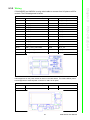
8.3 Pin Assignment and Wiring
8.3.1 Pin Assignment
The following table and figure shows the pin assignments of the LAN connector on
the iDoor I/O module for PCM-24R1TP.
Description of PIN Use - CN2
PIN1
TX_D0+
PIN7
PIN2
TX_D0-
PIN8
BI_D3-
PIN3
RX_D1+
PIN9
LAN_ACT#
PIN4
BI_D2+
PIN10
+V3.3_LAN
PIN5
BI_D2-
PIN11
LAN_LINK1000#
PIN6
RX_D1-
PIN12
LAN_LINK100#
PCM Series User Manual
46
BI_D3+
The PCM-24R1TP uses a wired cable to connect from the I/O plate tothe mPCIe
module. The PIN assignment is below.
Description of PIN Use - CN1
GND
PIN9
NC
PIN2
+V3.3_LAN
PIN10
NC
PIN3
NC
PIN11
LAN_MDI0+
PIN4
NC
PIN12
LAN_MDI0-
PIN5
LAN_LINK1000# PIN13
LAN_MDI1+
PIN6
+V1.9_LAN
LAN_MDI1-
PIN14
PIN7
LAN_ACT#
PIN15
LAN_MDI2+
PIN8
LAN_LINK100#
PIN16
LAN_MDI2-
The existing cable length may not enough. Advantech can help to customize the
cable for system inquires.
47
PCM Series User Manual
PCM-24R1TP-AE
PIN1
Chapter 8
8.3.2 Wiring
PCM Series User Manual
48
Chapter
9
9
PCM-24R2PE-AE
2 Port Giga LAN/w PoE mPCIe,
RJ45
9
PCM-24R2GL-AE
2 Port Giga LAN mPCIe, RJ45
Sections include:
Initial Inspection
Driver and Advantech Device
Manager Installation
Pin Assignment and Wiring
9.1 Initial Inspection
You should find the following items inside the shipped package:
PCM-2400 Communication Module:
– PCM-2400 mini-PCIe Card
– I/O plate
– Power board (For PCM-24R2PE-AE only)
– Wire Cable
PCM-2000 DVD-ROM including:
– User Manual
– Industrial Communication Driver, Utility and mini-PCIe communication card
The PCM-24R2PE was carefully inspected mechanically and electrically before it
was shipped. It should be free of marks and scratches and in perfect working order
when received.
As you unpack the PCM-24R2PE, check for signs of shipping damage (damaged
box, scratches, dents, etc.). If it is damaged or it fails to meet specifications, notify
our service department or your local sales representative immediately. Also notify the
carrier. Retain the shipping carton and packing material for inspection by the carrier.
After inspection we will make arrangements to repair or replace the unit. When you
handle the PCM-24R2PE, remove it from its protective packaging by grasping the
rear metal panel. Keep the anti-vibration packing. Whenever you remove the card
from the PC, store it in this package for protection.
Warning! Discharge your body’s static electric charge by touching the back of the
grounded chassis of the system unit (metal) before handling the board.
You should avoid contact with materials that hold a static charge such as
plastic, vinyl and Styrofoam. Handle the board only by its edges to avoid
static damage to its integrated circuits. Avoid touching the exposed circuit connectors. We also recommend that you use a grounded wrist
strap and place the card on a static dissipative mat whenever you work
with it.
PCM Series User Manual
50
9.2.1 Introduction
This chapter describes the driver installation, configuration and removal procedures
for the mentioned Windows operating system. We strongly recommend that you
install the software driver before you install the hardware into your system.
When you follow the startup manual to install the module appropriated. Please follow
the steps below to install Advantech PCM-24R2PE Driver.
1. Go to Device Manager and you will find an error in "Other devices"
2.
Get the driver from the DVD or Intel website, click it, then run the driver and
select “I agree” to continue the installation.
51
PCM Series User Manual
PCM-24R2GL-AE
9.2.2 Installation
Chapter 9
9.2 Driver Setup & Installation- Advantech Device
Manager Installation
3.
Select “Next ” to continue installation.
4.
Select “I accept the terms in the license agreement” to continue installation
and click “Next”
5.
Select “Driver for Windows Device Manager Intel® PROSet” to continue the
installation.
PCM Series User Manual
52
Select “Install” and start to installation.
7.
Select “Finish” to complete the installation.
8.
After the hardware has been installed, the card will be automatically detected.
Open Device Manager to check it.
PCM-24R2GL-AE
53
Chapter 9
6.
PCM Series User Manual
9.2.3 Uninstall
Go to Device Manager to check the device you want to remove.
1.
Go to Control Panel and select “Intel® Network Connections 19.1.51.0” and
click “Uninstall”
2.
Select "Yes" to continue the removal process.
PCM Series User Manual
54
4.
Select "Yes" to continue the removal process.
5.
Select "Finish" to complete the uninstallation process.
55
PCM-24R2GL-AE
In “Remove Options” panel, just select "Remove" to continue the process.
Chapter 9
3.
PCM Series User Manual
9.3 Pin Assignment and Wiring
9.3.1 Pin Assignment
The following table and figure shows the pin assignments of the LANs connector on
the iDoor IO module for PCM-24R2PE and PCM-24R2GL
Description of PIN Use
PIN1
MDIO+
PIN7
MDI3+
PIN2
MDIO-
PIN8
MDI3-
PIN3
MDI1+
PIN9
LED3_LINK1000#
PIN4
MDI2+
PIN10
LED2_LINK100#
PIN5
MDI2-
PIN11
+V3.3SB
PIN6
MDI1-
PIN12
LED1_ACT#
PCM Series User Manual
56
PCM-24R2PE and 24R2GL is using wired cable to connect from I/O plate to mPCIe
module. The PIN assignment is below.
Description of PIN Use
+V3.3SB
PIN16
LAN0_LED2_LINK100#
PIN2
PLTRST#
PIN17
LAN1_LED1_ACT#
PIN3
MDI_1_3N
PIN18
LAN0_LED1_ACT#
PIN4
MDI_1_2P
PIN19
GND
PIN5
MDI_1_3P
PIN20
GND
PIN6
MDI_1_2N
PIN21
MDI_0_2P
PIN7
GND
PIN22
MDI_0_3P
PIN8
GND
PIN23
MDI_0_2N
PIN9
MDI_1_0N
PIN24
MDI_0_3N
PIN10
MDI_1_1N
PIN25
GND
PIN11
MDI_1_0P
PIN26
GND
PIN12
MDI_1_1P
PIN27
MDI_0_0P
PIN13
LAN1_LED3_LINK1000#
PIN28
MDI_0_1N
PIN14
LAN0_LED3_LINK1000#
PIN29
MDI_0_0N
PIN15
LAN1_LED2_LINK100#
PIN30
MDI_0_1P
The PCM-24R2PE will need an additional 24VDC from the internal power source, refer to the
PIN assignment on the power board as shown in the table below. The PCM-24R2PE power
board supports an external power connector on CN1 as an option,
Description of PIN Use
PIN1
DCIN24V
PIN3
GND
PIN2
DCIN24V
PIN4
GND
57
PCM Series User Manual
PCM-24R2GL-AE
PIN1
Chapter 9
9.3.2 Wiring
PCM Series User Manual
58
Chapter
10
10
PCM-24U2U3
Sections include:
Initial Inspection
Driver and Advantech Device
Manager Installation
Pin Assignment and Wiring
10.1 Initial Inspection
You should find the following items inside the shipped package:
PCM-24U2U3 Communication Module:
– PCM-24U2U3 PCI Express Mini Card
– 2-port USB3.0 I/O plate
– Wired signal Cable
– Wired power Cable
PCM-2000 DVD-ROM including:
– User Manual
– Industrial Communication Driver, Utility and mini-PCIe communication card
The PCM-24U2U3 was carefully inspected mechanically and electrically before it
was shipped. It should be free of marks and scratches and in perfect working order
when received.
As you unpack the PCM-24U2U3, check for signs of shipping damage (damaged
box, scratches, dents, etc.). If it is damaged or it fails to meet specifications, notify
our service department or your local sales representative immediately. Also notify the
carrier. Retain the shipping carton and packing material for inspection by the carrier.
After inspection we will make arrangements to repair or replace the unit. When you
handle the PCM-24U2U3, remove it from its protective packaging by grasping the
rear metal panel. Keep the anti-vibration packing. Whenever you remove the card
from the PC, store it in this package for protection.
Warning! Discharge your body’s static electric charge by touching the back of the
grounded chassis of the system unit (metal) before handling the board.
You should avoid contact with materials that hold a static charge such as
plastic, vinyl and Styrofoam. Handle the board only by its edges to avoid
static damage to its integrated circuits. Avoid touching the exposed circuit connectors. We also recommend that you use a grounded wrist
strap and place the card on a static dissipative mat whenever you work
with it.
Note!
1.
2.
3.
4.
5.
6.
PCM Series User Manual
Power requirements: 5 ~ 24 VDC, 10 W (Max)
Power consumption: 5 V @ 900 mA (Max)
Full-size PCI Express Mini Card Revision TM 2.0
With xHCI specification compliance
Universal Serial Bus 3.0 specification Rev. 1.0 compliant
Operating Temperature: - 20 ~ 60°C ( - 4 ~ 140°F)
60
10.2.1 Introduction
This chapter describes the driver installation, configuration and removal procedures
for the mentioned Windows operating system. We strongly recommend that you
install the software driver before you install the hardware into your system.
10.2.2 Installation
When you follow the startup manual to install the module appropriated. Please follow
the steps below to install Advantech PCM-24U2U3 Driver.
1. Select "Next" to continue the installation.
2.
Select “I accept the terms of the license agreement”, and then click "Next" to
continue the installation.
61
PCM Series User Manual
Chapter 10 PCM-24U2U3
10.2 Driver Setup & Installation- Advantech Device
Manager Installation
3.
Select "Install" to continue the installation.
4.
After a while, the installation will be complete.
5.
After the hardware has been installed, the card will be automatically detected.
PCM Series User Manual
62
1.
In the Control Panel, click "Renesas Electronics USB 3.0 Host Controller Driver"
then uninstall.
2.
After a while, the uninstallation will be complete.
63
PCM Series User Manual
Chapter 10 PCM-24U2U3
10.2.3 Uninstall
10.3 Pin Assignment and Wiring
10.3.1 Pin Assignment
The following table and figure shows the pin assignments of the USB connector on
the iDoor IO module for PCM-24U2U3.
PIN Assignment of USB Type-A Connector (9-Pin)
Description of PIN Use
PIN1
VBUS
PIN6
SSRX+
PIN2
D-
PIN7
GND
PIN3
D+
PIN8
SSTX-
PIN4
GND
PIN9
SSTX+
PIN5
SSRX-
PCM Series User Manual
64
The PCM-24U2U3 utilizes wired cable to connect I/O plate and mPCIe module. The
PIN assignments are listed below.
I/O board overview
CN1_1 - I/O board to mPCIe Cabling
Description of PIN Use
PIN2
NC
PIN13
USB3_y_TXDP2
PIN3
NC
PIN14
GND
PIN4
USB3_RXDP1
PIN15
GND
PIN5
USB3_RXDN2
PIN16
USB2_DM1
PIN6
USB3_RXDP1
PIN17
USB2_DM2
PIN7
USB3_RXDP2
PIN18
USB2_DP1
PIN8
GND
PIN19
USB2_DP2
PIN9
GND
PIN20
NC
PIN10
USB3_y_TXDN1
PIN11
USB3_y_TXDN2
PIN12
USB3_y_TXDP1
65
PCM Series User Manual
Chapter 10 PCM-24U2U3
10.3.2 Wiring
VIN1- Internal Power Cabling
Description of PIN Use
PIN1
+VIN (5V~24V)
PIN3
GND
PIN2
+VIN (5V~24V)
PIN4
GND
PCM Series User Manual
66
Appendix
A
A
PCM-2300MR-AE
//
A.1 Initial Inspection
*******************************************************************
// * Program
: CheckZ.cpp
// * Description
: Demo program for file access
// *
// * APIs used
: GetLogicalDrives, fopen_s, fscanf_s, fprintf, fclose
// *
// * Date
: 1/31/2013
Advantech Co., Ltd.
//*******************************************************************
//
#include "stdafx.h"
#include <windows.h>
// The default drive letter of NVRAM Disk is 'Z'
#define DEFAUT_HD_LETTER 'Z'
int _tmain(int argc, _TCHAR* argv[])
{
DWORD dw;
dw = GetLogicalDrives();
char ch = DEFAUT_HD_LETTER;
int n;
char pathInOut[50] = {0};
char bufferOut[] = "0123456789abcdefghijklmnopqrstuvwxyz";
char bufferInput[50] = {0};
errno_t ErrRet = 0;
FILE *fp_r = NULL;
FILE *fp_w = NULL;
n = ch - 'A';
// Step 1: To check if Z drive exists.
printf("\nStep 1: Check %c Drive.\n", ch);
if( (dw != 0) && (dw >>= n) != 0 )
{
printf("There is a %c drive.\n", ch);
}
else
{
printf("There is NO %c drive.\n", ch);
exit(1);
}
// Step 2: Prepares the path for Input and Ouput
printf("\nStep 2: Prepares the path.....\n");
sprintf_s(pathInOut, 100, "%c:\\inout.txt", ch);
printf("PATH for Input and Output: %s\n", pathInOut);
// Step 3: Writes something to a file....
printf("\nStep 3: Writes something to a file....\n");
ErrRet = fopen_s(&fp_w, pathInOut, "w");
if( ErrRet != 0 )
{
printf("Failed to open %s !!\n", pathInOut);
exit(1);
}
else
{
// Output data to the text file.
PCM Series User Manual
68
}
// Step 4: Reads a file and displays its content on the screen.
printf("\nStep 4: Reads a file and displays its content.....\n");
ErrRet = fopen_s(&fp_r, pathInOut, "r");
if( ErrRet != 0 )
{
printf("Failed to open %s !!\n", pathInOut);
exit(1);
}
else
{
// Reads the content and shows it to console.
fscanf_s(fp_r, "%s", bufferInput);
printf("%s\n", bufferInput);
// Close file handle.
fclose(fp_r);
fp_r = NULL;
}
system("pause");
return 0;
69
PCM Series User Manual
Appendix A PCM-2300MR-AE
fprintf(fp_w, "%s", bufferOut);
// Close file handle.
fclose(fp_w);
fp_w = NULL;
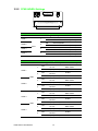
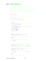
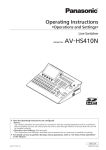
A.2 Diagnostic LEDs
LED1
LED2
Table A.1: Diagnostic LED Definitions
LED
Light On
Light Off
LED 1 - Chip Status
It’s working
It’s not working
LED 2 - MRAM Access Status MRAM is being accessed
PCM Series User Manual
70
MRAM isn’t being accessed
Appendix A PCM-2300MR-AE
71
PCM Series User Manual
www.advantech.com
Please verify specifications before quoting. This guide is intended for reference
purposes only.
All product specifications are subject to change without notice.
No part of this publication may be reproduced in any form or by any means,
electronic, photocopying, recording or otherwise, without prior written permission of the publisher.
All brand and product names are trademarks or registered trademarks of their
respective companies.
© Advantech Co., Ltd. 2014