1
AstroHub
Installation and User's Guide
November 25, 2004
Version 1.11
Copyright © 2004, Aquest, Inc.
All Rights Reserved
Aquest, Inc.
Boca Raton, FL
AstroHub
User's Guide
AstroHub is a Trademark of Aquest, Inc.
FocusAide, PCFocus, and "Plug and Guide" are Trademarks of Aquest, Inc.
AstroHub™ User's Guide
TABLE OF CONTENTS
Introduction..................................................................................................................3
Feature Description.....................................................................................................4
Overall Architecture and Packaging...........................................................................4
Base Unit Features ....................................................................................................4
Plug-ins ......................................................................................................................5
Common Stepper................................................................................................5
Aux Port ..............................................................................................................6
Control Port.........................................................................................................6
Software Support .......................................................................................................6
Software Installation ...................................................................................................7
Registration.........................................................................................................8
AstroHub Hardware Setup..........................................................................................8
Setting up the Base AstroHub....................................................................................9
Jumper Settings - Table 1........................................................................................10
Installing Plug-ins.....................................................................................................11
USB Device Enumeration by Windows....................................................................12
Connecting External Power .....................................................................................13
Running the Set Up Program...................................................................................14
Set Up Program Screens .........................................................................................14
System Connection ...................................................................................................19
Basic Operation of Your AstroHub ..........................................................................22
Software Automation and Scripting ........................................................................25
Use with ASCOM .......................................................................................................26
Appendix A - Automation Interfaces .......................................................................27
Appendix B - COM Port Reconfiguration ................................................................28
Appendix C - Connector Pin-outs ............................................................................30
Port1/Port2 Plug-in Connectors ...............................................................................30
Misc. Port Plug-in Connector ...................................................................................30
Filter Wheel Connector (from Aux Port Plug-in).......................................................30
Guider Connector.....................................................................................................31
PCFocus Connector.................................................................................................31
Power Connectors (all) ............................................................................................31
Appendix D- Plug-in Configurations........................................................................32
i
AstroHub™ User's Guide
Introduction
Congratulations on your purchase of the revolutionary AstroHub!
The AstroHub will significantly improve the reliability of your astronomy system while greatly
reducing system cabling, eliminating multiple adapters and control units, and generally simplifying
the overall system. With the AstroHub and available plug-ins your current suite of software will
function as it always did since the overriding AstroHub design requirement was compatibility with
all existing software and popular astronomy and imaging hardware products.
A single USB cable from your computer to the AstroHub and direct short cables from it to all of
the elements of your astronomy system is all you need. (Your current cables will generally work
but shorter ones will be better). Most products with some form of hand box or control unit can be
operated without the provided control unit as all of these functions are part of the AstroHub
system.
While any software currently available can be used with the AstroHub, additional function and
features are available through additional software provided with your AstroHub. A Windows COM
(Component Object Model) object is provided which can be used to write simple to very complex
scripts to control you system operation and/or included in application software of any type. Linux
users can utilize the detailed command protocol to do much of the same function at the serial
command level.
An ASCOM telescope hub is provided which, along with the freely available ASCOM platform,
can further extend the features available to you. For example, mount power control of the
telescope can be automatically provided as part of Park and Unpark functions of all ASCOM
telescope drivers.
Please read this user's manual and those provided for the plug-ins available or shipped with your
AstroHub. There are many, many features that you will want to acquaint yourself with and put
into action as your system warrants.
Also, a collection of Tips, Techniques, and other miscellaneous useful information will be
maintained at the following link. Please feel free to email Aquest Tech Support if you have any
additional items you wish to contribute or for any help you may require in installing or using your
AstroHub.
http://www.aquest-inc.com/AstroHub/astrohub_tips.htm
Updates or additional software, as it becomes available, may be freely downloaded from:
http://www.aquest-inc.com/AstroHub/downloads.htm
If you would like to be alerted to any AstroHub news, the availability of new or updated software,
or the addition of information in the Tips and Techniques section, please email us to be added to
the email distribution list. Of course, we will only use your address for this purpose and you can
request to be removed from the list at any time.
Thank you purchasing our products. Enjoy them!
Note: Please install the AstroHub software prior to connecting the AstroHub to your computer.
Page 3 of 33
AstroHub™ User's Guide
Feature Description
It is useful to understand the basic features and operation of the AstroHub prior to software and
hardware installation. Here is a brief description. Detailed setup and usage information will be
given later in this manual
Overall Architecture and Packaging
The AstroHub consists of a compact unit housing a base board and up to two "plug-in cards".
Most of the system is powered from the upstream USB host. An external power input can be
supplied for providing power to downstream USB ports or other peripheral devices such as
focusers or filter wheels. Manual or automatic (on Park or Unpark) mount power switching is
provided and the mount power can optionally be used as the external power supply thus saving
another cable. (See the Power section below for more information).
The base board houses a 7 port USB 2.0 (USB 1.1 compatible) hub. This is connected via a
standard USB cable to the host PC.
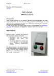
Base Unit Features
Two downstream USB 2.0 ports are available for use with CCD cameras or any other USB device
(including a USB Hub). The base unit provides a Focuser/RS-232 port and a Mount/RS-232 port.
These ports are general purpose RS-232 ports but have optionally useable special functions as
well.
The Focuser port has an onboard PCFocus™ system capable of driving any motorized, encoder
based focuser (e.g. JMI™ focusers, Meade Microfocuser™, etc.). The PCFocus system can be
utilized with any ASCOM supported software (e.g. Maxim DL/CCD™) or with the included
FocusAide software package. Since a PCFocus ASCOM driver is available this function is fully
scriptable as are most functions of the AstroHub and can be driven with any commercially
available or custom software supporting ASCOM.
The Mount port is also a fully functional RS-232 port and is designed to be a pass-through to the
mount from software such as TheSky, SkyMap, or any other software that can command
telescope mount "GoTo" operations. The AstroHub mount channel has a microprocessor which
listens to serial communication between the PC and the mount and can process special
commands assigned to it such as power control of the mount. Despite most mounts operating at
9600 8-N-1 serial port parameters some mounts depart and operate at other speeds (e.g.
Takahashi Temma™ mounts operate at 19200 8-E-1). Provision for 4 different Baud rates and
parity settings is included through the use of jumpers on the base board.
Also included in the base AstroHub is a full Guider interface capable of being driven by any
application software with either classic guiding or timed pulse guiding. The guider system can
automatically sense an active low (e.g. ST-4) interface or an active high (e.g. older Gemini
mounts) connected to it and simply guide with no relay or opto-isolator boxes through our "Plug
and Guide"™ technology. The AstroHub includes four colored guide direction LEDs which
illuminate while any guiding action is in process.
Connectors on the base board as well as connected to plug-ins are of the same type and gender
as the devices they are replacing or emulating. For example, the Focuser port consists of 3
connectors. A DB9M for the standard RS-232 output, a RJ-11/6 for direct connection to a JMI
Page 4 of 33
AstroHub™ User's Guide
"DRO Encoder" or Aquest PCFocus-LX™ for user with the Meade Microfocuser™, and a 3.5mm
stereo audio connector for attaching a +/-9V or ground closure button box for manually moving
the focuser are included.
To accomplish the goal of a single cable from the PC to the AstroHub and a series of short, direct
run cables from the AstroHub outputs to the scope, cameras, and astronomy system
components; a set of plug-in cards have been developed. To eliminate the need for the
multitude of "control boxes" for devices such as focuser, filter wheels, etc., these functions are
performed by microprocessors on the plug-in cards and replace the control boxes completely.
For example, if the Common Stepper plug-in is configured through its jumpers to be a RoboFocus
controller, it totally performs this function including the temperature reporting function and
completely emulates the RoboFocus supplied control unit so it is no longer needed.
Plug-ins
There are currently three plug-in cards available for the AstroHub. More will be developed as new
functions or devices are introduced into the market. Two plug-in sockets are provided on the
AstroHub base board allowing any combination of up to two plug-ins to be installed. This includes
two plug-ins of the same type.
Each plug-in is the same size and plugs into the base board on two rigid connectors and one
ribbon cable. The ribbon cable is used to change the pin-out on the base board output connector
such that the device being emulated can use the same cable as was used with the provided but
now unused device control box. For example, if the Common Stepper plug-in is configured as a
True Technology™ filter wheel controller, the ribbon cable would be installed so the associated
AstroHub output connector appeared the same as the connector on the True Technology control
unit.
As is the case of the Mount and Guider microprocessors on the base board, all microprocessor
based plug-in cards have firmware that may be re-flashed by users or dealers to allow for rapid
updates or increased function. This is done through the single USB cable from the host PC using
a utility program and flash memory data file.
The available plug-in cards and a brief description of each follow.
Common Stepper
This microprocessor based card has the ability to become these devices control units:
RoboFocus™ Focuser (including temperature compensation)
True Technology™ Filter Wheel
Finger Lakes Instruments™ Focusers and Filter Wheels.
Optec™ Focuser
The device type is determined by jumpers on the plug-in and direct the resident firmware to
execute so as to accomplish the required function. New devices can easily be added by
additional firmware module development. The new firmware can be flashed into the
microprocessor by using the USB cable connected to the AstroHub.
The compatibility of the emulation is designed to be 100% so the device's native control program
can be used as well as any commercially available or personally developed software. Existing
scripts using standard drivers (e.g. ASCOM) will also work unmodified. For example, The
RoboFocus Control Program (RFCP) will work unmodified.
Page 5 of 33
AstroHub™ User's Guide
Aux Port
The Aux Port plug-in can be used to provide either an additional USB 2.0 downstream port or an
additional RS-232 port. Jumpers on the card select between USB or RS-232 outputs.
Connectors on the base board provide the output means for either port. Note that if the AstroHub
is connected to a USB 1.1 upstream host the USB outputs from the AstroHub will be USB 1.1
In addition, a special output connector is provided for driving SBIG and Homeyer filter wheels
used without a camera. Software capable of driving this output (e.g. Maxim DL/CCD™) is
required. The Aux Port card must be configured as a serial port card for these functions to work.
The serial port can be used for other things when a filter wheel is not being used as separate
connectors are provided for the filter wheel(s) and the RS-232 port. The only limitation is one
imposed by Windows® where only one program can open a specific serial port at one time.
Control Port
The Control Port is a general purpose control card which includes the following:
4 optically isolated inputs
4 optically isolated outputs
SPDT relay contacts
Persistent user accessible memory
Digital voltage measurement of main and mount power inputs
The 4 digital inputs are software readable either by external polling of scripts and software or
internal polling by using the supplied COM class and associated control port automation interface.
This class is available in the supplied Astro_Hub.OCX which is fully described in Appendix A to
this manual. In addition, the automation interface provides for an event which fires when any of
the four input lines changes state.
Two of the inputs are additionally connected to the associated serial port CTS and DSR lines.
This allows application software to use operating system services to "immediately" be notified if
one of these lines changing state. A software automation level event is also provided. This
feature provides for notification of two of the four input lines changing state much more quickly
than in a polling environment.
Outputs can be statically set via software or script or accurately pulsed from 10ms to 9999ms.
Pulsing can "arm" certain outputs to be fired on another event or fired immediately. All pulsed
outputs fire an event when the pulse time as elapsed. A fifth "virtual output" is provided for
general use for accurate delays in software or any other use desired.
The Control Port also provides for user accessible persistent memory useable from scripts and
application software. There are 32 Words (2 bytes) and 32 Longs (4 bytes) available for any use
and will retain values indefinitely when the power to the AstroHub is off.
The main 12V input voltage as well as the mount power, if connected, are continuously measured
and the results provided to scripts and application software requesting this information.
Software Support
The AstroHub is provided with a complete installation program that installs all required software
and optionally installs several other software packages as described below.
The installer installs documentation (such as this manual), a setup and control program, the
AstroHub software automation interface, registry settings, and all hardware drivers required for
Page 6 of 33
AstroHub™ User's Guide
USB enumeration and operation. The software should be fully installed before the AstroHub
is connected to the PC.
Set Up Program - A full function set up program is provided which configures the AstroHub and
plug-ins to your preferences as well as allows for basic functional testing of the complete setup.
A full section is provided below outlining the operation of set up program.
Astro_Hub.OCX - As has been already described, a COM class is provided which includes
multiple interfaces to control and operate the AstroHub. This is not required at all if you wish to
operate your system with commercially available software. Its use can significantly enhance the
features available to you with your AstroHub but is optional.
The automation interfaces included in the COM object are:
Control Port
Mount
TelescopeStatus
Guider
Show Devices Utility - Since the AstroHub has multiple embedded USB to serial adapters, these
can be "installed" at various COM ports as determined by the operating system. See Appendix B
for more information on how to exert more control over this process. This ShowDevices utility is a
quick way to see what AstroHub devices are installed and on what COM Port.
AstroHub.exe - A full function ASCOM hub based on the Plain Old Telescope Handset (POTH) by
Jon Brewster is provided which utilizes the AstroHub mount interface to control power to the
mount automatically or manually. The power control is integrated with the Park/Unpark facilities
and can optionally power down the mount when it parks.
Software Installation
Warning: The hardware should NOT be connected prior to the software installation.
The software for the AstroHub is designed to run under Windows 98SE, 2000, and XP. The
computer to be connected to the AstroHub requires at least one USB port. The USB port can be
either USB 2.0 or USB 1.1 and the AstroHub will operate at whatever speed the upstream port
runs at.
During the software installation, ASCOM software may be installed (with your permission) which
will enhance the use of your AstroHub. It is recommended that install at least the runtime portion
of the ASCOM Platform if it is not already installed on your system. If you already have ASCOM
installed you will not be asked to re-install it and only the PCFocus ASCOM driver will be updated
and the AstroHub telescope hub installed.
In addition, FocusAide™ and PCFocus™ are provided at no charge to AstroHub users. If the
installation program finds an existing installation of FocusAide it will update required portions
without changing any of your settings. If FocusAide is not installed, it will be and you will need to
register the software with your dealer to use it beyond the 15 day trial period. Details of this are
explained below.
Page 7 of 33
AstroHub™ User's Guide
To install software:
1.
2.
3.
4.
Insert the AstroHub CD in the CD-ROM or DVD-ROM drive
Click Start
Click Run
Type <drive letter>:Setup and press Enter (where <drive letter> is the letter of your CDROM or DVD-ROM drive)
5. Follow on-screen directions
Registration
None of the software provided with your AstroHub requires registration except for FocusAide
which is a full function version of the commercially available product and must be registered to
use it past 15 days of the first use. Registration codes are provided at no cost to AstroHub
owners.
FocusAide will operate fully for 15 days to allow you time to contact your dealer to obtain a
registration code. We will require the information presented on the registration screen
(Registered To Name, Product Code, Use (Choose "Other"), and the serial number from the
bottom of your AstroHub unit.
Simply start FocusAide, click the Register button on any of the Settings/Status tabs and enter
the information. A Product code will be generated for you. You may copy and paste the
information into the form at the Aquest web site by using the Copy to Clipboard button. Be sure to
provide a valid email address as the registration code will be emailed to you. When you receive
the registration code simply enter it in to the registration screen and press Enter or click OK.
Your software is now fully functional and the registration screen will no longer appear when the
program starts up. If you need to refer to the registered name or product code, click the Register
button on the Settings/Status tabs.
AstroHub Hardware Setup
All of the drivers and software required for operation of your AstroHub have been installed in the
required place on your hard disk. This includes all of the USB "Plug and Play" files. Simply
connecting the hardware will begin the driver installation process which should proceed
automatically except for acceptance of certain steps by you as the installation proceeds.
Please complete reading this section of the manual before connecting your hardware to
ensure a smooth, trouble free installation. Your AstroHub is a complex device and much
work has gone into assuring that installation and setup will run cleanly. It is important to
follow the installation procedure exactly.
There are five steps to installing and setting up the hardware:
1. Setting up the AstroHub base board jumpers to your preferences
2. Installing Plug-ins
3. Initial USB device enumeration by Windows
4. Connecting external power
5. Running the Set Up program to complete setup and perform tests to assure full function
Page 8 of 33
AstroHub™ User's Guide
Setting up the Base AstroHub
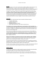
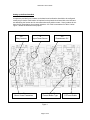
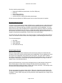
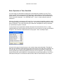
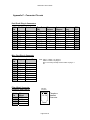
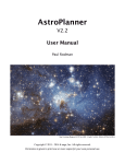
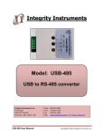
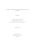
Jumpers are provided in six locations on the base board to allow the AstroHub to be configured
exactly as you desire. Each location is imprinted on the printed circuit board with a Jxx label and
text describing the function and in most cases what each position means. Some locations do not
have the full nomenclature due to space limitations. All of this is summarized in Table 1 below.
Figure 1 shows the locations of the jumpers
J30
Relay Contacts
J31
Mount Comm Parameters
J3
Input Power Source
J25
Downstream +5V
J13, J14, J15
Focuser Button Type
Figure 1
Page 9 of 33
J23
PCFocus Enable
AstroHub™ User's Guide
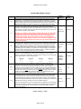
AstroHub Base Board Jumpers
Jumper
J30
Function
Mount power relay contact configuration as either Normally Open (NO) or Normally
Closed (NC). In the NO position the mount power is off if the AstroHub is off and NC
allows to power to the mount to be on with the AstroHub off. There is also a software
setting to specify whether the AstroHub firmware starts with the relay energized or not.
With these two settings any power up situation can be configured to suit your needs
AstroHub Power Source is a way to use the mount power input voltage as the source for
the rest of the AstroHub instead of connecting two power cables to the AstroHub.
Normally, 12V input power is used for the AstroHub but any voltage from 10V to 28VDC
can be used. This jumper simply connects the mount input power connector to the 12V
input connector internal to your AstroHub.
Available
Selections
Factory
Default
NO
NO
NC
12V Input
12V Input
Mount Input
J3
J25
Warning: The "12V power input voltage" is delivered to any focuser, filter wheel,
or other device that uses 12V external power. Be certain that if you power your
AstroHub from mount power with this jumper that all of your peripherals can
operate on that voltage. Some mounts operate at 18V or more and therefore
could damage a device designed to operate at 12V. No internal regulation of this
voltage is done except for internal use 5V so be sure your mount voltage is safe
for your other devices.
Most of the AstroHub baseboard and some of the plug-in circuitry operate from the USB
VBUS power line. While the current draw is very low, some USB ports or hubs require
an external power supply if any load is connected to them. This jumper allows you to
select the VBUS line or the internal 5V power supply (generated from the 12V power
input) to power much of the internal circuitry. If you find your USB port or hub will not
adequately power the AstroHub you can either use an external supply to the upstream
port/hub or switch this jumper and use the internal 5V supply. The later necessitates
connection of the 12V external power input on the AstroHub.
Most mounts operate with communication parameters of 9600 Baud, 8 data bits, no
parity, and 1 stop bit (9600 8N1). There are some exceptions to this so provision is
made for various sets of parameters. Set these jumpers to match your mounts RS-232
(Go To) requirements. Jumper positions [] are:
J31
9600 8N1
[] []
o o
J13
J14
J15
J23
19200 8E1
[] o
o []
9600 8E1
o []
[] o
9600 8O1
o o
[] []
There is a special connector available for connecting an external "button box" to
manually move the focuser when using the onboard PCFocus. If you have a JMI
focuser you may use the simple box provided with your focuser which supplies +/-9V to
the focuser. If these jumpers are set the opposite way you can use a simple button box
with two buttons which close to ground. A 3.5mm stereo audio connector is required in
the latter case and a mono audio connector is supplied with the JMI button box. (Note:
provision for an external manually control for stepper motor based focusers is also
provided. See the Common Stepper Plug-in manual for details)
PCFocus Enable. Windows does strange things during the boot process which causes
transient signals on the serial port lines during USB enumeration. If this jumper were
not provided a PCFocus connected focuser would move off the current focus position.
This jumper has three states, one of which is the "dynamic" setting. Here the PCFocus
circuit is automatically enabled whenever PCFocus.exe, FocusAide.exe or the PCFocus
ASCOM driver is running. The PCFocus circuit is disabled otherwise.
USB VBUS
Internal
5V
9600 8N1
19200 8E1
9600 8E1
9600 8O1
Jumper Settings - Table 1
Page 10 of 33
9600 8N1
3 jumpers set:
+/- 9V
+/- 9V
Ground
Closure
Off
Dynamic
Always On
Note: The onboard PCFocus circuit only requires the Focuser/RS-232 port it is attached
to when it is operating (i.e. with any of the three programs listed above). At other times
the serial port can be used for any other purpose. The dynamic setting makes the
switch-over automatic.
USB VBUS
Dynamic
AstroHub™ User's Guide
Installing Plug-ins
AstroHub plug-ins are very easy to configure and install. Some plug-ins have jumpers that need
to be set and all require that the supplied ribbon cable be properly connected. Consult Appendix
D of this manual or the back of the card that came with your plug-in(s) to see the connector and
jumper configuration options. You should set the jumpers on your plug-ins to the configuration
you wish and determine which ribbon cable connector you will use before proceeding with the
plug-in installation.
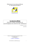
All plug-ins are installed the same way in terms of connection to the base board. There are two
rigid connectors and a ribbon cable used to make these connections. It makes no difference
which base board socket you insert a plug-in into as the plug-ins report their position and type to
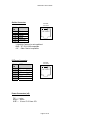
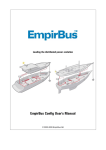
the internal firmware and setup program when it runs. For reference, if you view the base board
with the USB IN connector up or away from you the, left side of the AstroHub unit is where Plugin 1 is and Plug-in 2 is on the right.
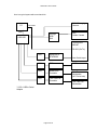
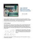
Also viewing the base board as above, you will note there are DB9F connectors at the bottom of
the board near the side of the printed circuit board on both sides. Right above them and at the
edge of the card are 2x5 header connectors where the ribbon cables go. Here is a drawing to
see where things are:
Rigid Connectors
USB IN
PORT 2
PORT 1
Ribbon Cable Connectors
Page 11 of 33
AstroHub™ User's Guide
The Port 1 external connector and part of the Misc. Port connector are associated with Plug-in 1
and Port 2 and the rest of the Misc. Port connector are for Plug-in 2.
To begin the installation, plug the ribbon cable into the base board connector so the cable is
pointing toward the center of the board and the unplugged ribbon cable connector is pointing up.
Determine which ribbon connector on the plug-in that you need to use from the information
provided with the plug-in. Some plug-ins only have one ribbon cable connector and others have
multiple ones. Position the plug-in card over the rigid connectors to see how they will align and
with the card in this orientation plug the free end of the ribbon cable into the plug-in card in the
appropriate connector.
A nylon spacer and 1" long screw were provided with your plug-in. These can be used to
mechanically secure the plug-in card to the base if desired. There is plenty of retention in the
rigid connectors so this isn't mandatory but you can assemble it this way if you choose. To do it,
remove one of the screws that are holding the printed circuit board into the base unit enclosure.
Position the nylon spacer over the hole and plug the plug-in card into the base board trapping the
spacer between them. Insert the 1" long screw through the plug-in and spacer and tighten it
gently so as to not strip the plastic bosses in the enclosure.
Whether or not the screw and spacer are used, assure that the two main connectors on the plugin card properly mate with the connectors on the base board. Also, assure the ribbon cable is
neatly folded over as required and not pinched against any component or connector.
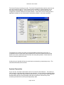
USB Device Enumeration by Windows
Windows has a system called "Plug and Play" that detects any device attached to the computer
and automatically installs and runs any software required for the device. Some people refer to
this as "Plug and Pray" as it is prone to problems. We have gone to great lengths to provide
accurate install files and drivers so this process will be trouble free.
When you plug the USB cable into your AstroHub, Plug and Play will install multiple devices. The
drivers for these are not "Microsoft Certified" but are nonetheless perfectly safe and reliable.
Unfortunately, Microsoft has programmed the operating systems to pop up a message box on
every device that installs. In addition to that, every device found will cause a "New Hardware
Found" box to appear and then another box will pop up requiring you to click "Finish. A fully
loaded AstroHub potentially contains 10 USB devices so as many as 30 pop-up boxes could
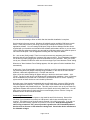
appear! You can eliminate 1/3 of the pop-up warnings by stopping Windows 2000 or XP from
warning you every time of an "unsigned driver".
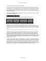
You can do this as follows:
Click Start | Control Panel | System | Hardware | Driver Signing and the following dialog should
appear. Disable driver signing by clicking "Ignore" and then clicking OK.
Page 12 of 33
AstroHub™ User's Guide
You can return the setting to Warn or Block after the AstroHub installation is complete.
One last point before we proceed: Windows will arbitrarily assign available COM ports to each
device. These may not be to your liking or at too high a number to be used in your current
application software. You can reassign COM ports using the Device Manager and the drivers
supplied with your AstroHub and reinstall all the software and hardware drivers or you can clean
up the COM port assignments before you start and have Windows assign your AstroHub ports to
low number COM ports. See the Appendix B dealing with this subject for details.
So... now we are (finally) ready! There is no need to connect any astronomy devices to the
AstroHub with plug-ins installed nor is external 12V power required. The full hardware installation
can be done by simply plugging the upstream USB cable into your AstroHub. Once you do this,
one by one, Windows will discover each new device and pop-up a "New Hardware Found" dialog.
Whenever a "New Hardware Found" dialog appears, click the option to find the installation files
automatically.
At this point, if you did not disable signed driver checking you will be warned that the software is
not certified by Microsoft (despite it already being installed or, in the case of the main internal
USB hub, a Microsoft supplied driver!!). Click OK and continue.
After a short time another dialog will appear telling you the device has been installed.... click
"Finish". Do this for each device until Windows has completed the installation. Note: In Windows
98, the installation will proceed with no intervention as Windows 98 isn't a "secure" operating
system and all of these checks are not included by Microsoft.
Note that many of the AstroHub embedded devices will install twice; once as a USB Controller
and then again as a COM Port. They can all be viewed in the Windows Device Manager or by
using the supplied utility ShowDevices.exe. This utility can be used to set up all your astronomy
application software that requires a COM port for the specific device being attached to. You can
print a copy of all the ports or simply use the on-screen display of them. See the "Using the
Software" section of this manual for details.
Connecting External Power
It is now time to connect external power to the AstroHub and finish the setup. Some of the
functions of your AstroHub run entirely on USB power in which case external power is not
required. The following list of functions require external 10V to 28V input power. If you are not
using any of these functions, external 12V power is not required. Note the warning above
about using an external "12V" power input that is greater than 12V if AstroHub powered
devices such as focuser or filter wheels are being used. Consult the device manufacturer
for allowable voltages.
Page 13 of 33
AstroHub™ User's Guide
Functions requiring external power:
Downstream USB ports (base board or Aux Port USB ports)
PCFocus
Mount Power switching
Common Stepper Plug-in
Aux Port Plug-in if using the filter wheel pulsed output
All other functions operate from USB bus power and no external input power is required.
Running the Set Up Program
You must run the supplied setup program AHSetUp.exe to complete the set up and perform tests
to assure everything is functioning. This program will automatically determine which COM Port
each device is on and open each port to assure communication can be established. For every
device found an entry in the left window will be created showing the device COM port and allow
selections of the "Properties" for each device. Clicking the top level AstroHub entry and any of
the Properties selections will bring up a separate panel with settings and tests for that device. An
example of each panel and explanation of each control on the panel follows.
The setup program will make entries in your system registry to record information other software
needs. This, as well as most functions of the setup program, is automatically performed for you.
To run the setup program:
1.
2.
3.
4.
Click Start
Select Programs
Select AstroHub
Click AstroHub Set Up
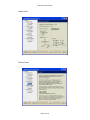
Set Up Program Screens
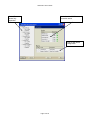
When the setup program starts it determines which devices are present in the AstroHub and
connects to each one to assure communication can be established. Errors or attempts to correct
the situation will be displayed if any problems are encountered. The green "LEDs" indicate
successful communication. The program opens to the main screen shown here. You can cause
the program to start with the device tree fully expanded by adding the word "expand" after the
program name in the Windows shortcut.
Clicking the Properties entry on any device will display the set up and test page for that device.
Each of these pages is shown below including information about the plug-in pages. The
AstroHub base board contains the Mount, Guider, and Focuser controllers. The following screen
shots show the Properties pages for these controllers.
The set up program main screen is shown below. Each port is listed and communications with
that port automatically established. Both plug-in sockets are queried to determine which plug-in
is installed. If all the "LEDs" are green you may proceed to each subsequent port or plug-in to set
it up and test it.
Page 14 of 33
AstroHub™ User's Guide
Device Tree
shown fully
expanded
Device list with COM Port
connection status
Plug-ins with device
configuration
Page 15 of 33
AstroHub™ User's Guide
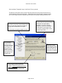
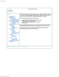
Click the Mount "Properties" entry in the Device Tree to proceed.
The Mount Control panel can be used to manually control the mount power as well as set up
various settings on the mount processor. Setting the mount communication jumpers to match
your mount's requirements is important and the results of the jumper setting are shown here.
Jumpers on the AstroHub base board can be
set so the mount power relay switches mount
power on when the AstroHub is off (NC) or
on only when the AstroHub is on (NO).
This line tells you how the jumpers are set.
The automation
interface for the
mount has provision
for setting a built-in
timer to power off
the mount in any
number of minutes.
This function can be
employed here or in
a simple script.
Check this box to have the relay
energize when the mount processor
starts (when the USB cable is
plugged in or the PC is booted).
Operation is such that "energized"
means power is connected to the
mount if the contact jumper is set to
Normally Open (NO)
Manually controls
mount power via the
power relay that you
can hear clicking as
this switch is toggled
Mount communication parameters
jumper settings found by the set up
program. Assure the jumpers are set to
match your mount. Change them here if
you change them on the base board
Page 16 of 33
AstroHub™ User's Guide
The Guider settings are made using the panel below.
The Guider Type will be correctly shown only if a ground connection exists between the mount
and the AstroHub. This will always be the case if mount power is switched through the AstroHub
or an RS-232 connection is made from the AstroHub to the mount. The guiding outputs will be
automatically switched to whichever type of mount is connected and this panel shows what type it
is (for information only).
All guiding software sends bytes of information to the guider to pulse the auto-guider input on the
mount. The bit configuration is:
0
0
0
0
b3
b2
b1
b0
where different software assigns different guide directions to the bits as follows:
Direction
North
South
East
West
*Default
Cookbook
b3
b2
b0
b1
Starlight Xpress*
b2
b1
b3
b0
Direct
b3
b2
b1
b0
This is not related to the CCD camera in use but the "relay box" or other guide unit such as the
STAR2000. These units interpret the bits differently as show in the table. Your AstroHub can be
set to emulate any of these protocols and the setting is saved in the guide processor's persistent
memory.
Warning: The Direction Test and Pulse Test controls will move your mount if it is connected.
The Direction Test controls are used to learn which direction the mount will move for a specific
input from the guide software into the AstroHub. The pin-outs and polarities of the AstroHub
Guider were carefully designed to allow you to simply unplug your current guider and plug the
AstroHub in its place and not have to make any settings changes in your guide software. There
is great confusion in the terminology, polarity, and even connector pin-outs in the industry so you
should verify that the settings in your guide software are still valid in terms of directions and even
swapping the X and Y axis.
The Pulse Test is similar in terms of moving the mount. You can "Arm" a direction by checking
the Arm box and clicking a direction. Then change the pulse duration, uncheck the Arm box and
click another direction. Both directions will start pulsing at the exact same time when the second
direction button is clicked and end at different times. The guider LEDs on the AstroHub unit will
flash accordingly. Some application software takes advantage of a feature such as this to make a
"diagonal move". Of course, if you click opposing directions the action will be nullified.
Page 17 of 33
AstroHub™ User's Guide
Guider Panel:
Focuser Panel:
Page 18 of 33
AstroHub™ User's Guide
The Control Port has no settings to make. The Control Port panel below contains controls to test
the entire Control Port plug-in. If two Control Ports are available in a single AstroHub, two of
these panels will be displayed. Note that the Raw Vin "12V" input as well as the Mount Vin
voltages are continually measured and made available. These values can be read by scripts or
application software by use of the AstroHub automation software or via serial commands.
The Stepper plug-in panel (not shown) will request additional information if the plug-in in
configured to drive a Finger Lakes Instrumentation device and that is whether the connected
device is a focuser or filter wheel and if the latter how many filter positions. Some basic test
function is also provided for this case.
At this point your AstroHub is fully set up and can be connected to you astronomy set up. The
next section describes how to do that.
System Connection
As you can see, the sides of the AstroHub are full of connectors and indicators. The function of
each connector on the AstroHub is printed on the end panel. You can connect the existing cables
you are using or obtain short cables with the same pin-outs and connector types. Most cables are
standard cables that are readily available unless the manufacturer of the device you are
connecting the AstroHub to used a special proprietary cable.
Page 19 of 33
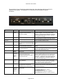
AstroHub™ User's Guide
The end panels of your AstroHub are shown below with a short description what the connector is
cabled to in your system. See Appendix C on connector pin-outs for details on specific
connectors.
Connector/Indicat
or
FOCUSER CTL
Type
Function
Comments
3.5mm
audio
Attach a "button box" for manually
moving the focuser using the
PCFocus Controller
Focuser RS-232
DB9M
Full RS-232 serial port
FOCUSER
PCFocus
USB PWR
RJ-11/6
PCFocus output
LED
USB RDY
LED
USB IN
USB-B
Indicates the hub controller has
applied power to downstream USB
ports
Indicates the USB 2.0 hub has
been enumerated and is active
Connection to a host PC USB 2.0
high speed USB port
The button box can be either as supplied with JMI
focusers (supplies +/- 9V) using a mono audio
connector or a box with two buttons that connect to
ground using a stereo audio connector. Set base
board jumpers accordingly
Useable for any other serial function when PCFocus
is not connected to the serial port through software
See the FocusAide and PCFocus User's manual found
in the FocusAide installation folder
Shows either VBUS or VCC downstream power
status.
USB OUT
USB-A
DUAL
MAIN PWR
2.1mm I.D.
5.5mm O.D.
Power
(tip +)
MOUNT PWR IN
2.1mm I.D.
5.5mm O.D.
Power
(tip +)
MOUNT RS-232
MOUNT PWR OUT
DB9M
2.1mm I.D
5.5mm O.D.
Two full function USB 2.0, high
speed ports
Nominal 12V input power for
running all functions in the
AstroHub not powered from USB
power from the host
Input power to be switch controlled
by the AstroHub
Full RS-232 serial port with a
microprocessor connected for
additional mount control function
Switched version of the MOUNT
PWR IN line
Hub controller chip flashes this LED as a health
monitor
If connected to a low or full speed USB 1.1 upstream
port, the hub controller with down speed to match the
speed as will all downstream ports.
12V or mount power must be connected
Allowable voltage range: 10V to 28V.
Note this voltage is directly fed to non-USB devices
powered by the AstroHub such as focusers, filter
wheels, etc. If other than 12V is used consult with
the device manufacturer on allowable voltage for
powering the attached device.
An internal jumper is provided in the AstroHub which
will internally connect this connector to the MAIN
PWR connector to save a power cable. Note the
caution about AstroHub powered devices.
Useable for any serial port function but typically
connected to the telescope mount's RS-232 input for
control such as "Go To"
The internal mount power relay is rated at:
Max. Switching Voltage: 250VAC, 220VDC.
Max. Switching Current: 5A.
Max Carrying Current: 2A @30VDC, 3A @20VDC
Expected Mechanical Life: Approx. 100 million operations.
Power
(tip +)
Page 20 of 33
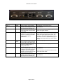
AstroHub™ User's Guide
Connector/Indicator
Type
Function
Comments
PORT 1
DB9F
See Appendix C and specific plug-in
documentation.
GUIDER NSEW
LED
GUIDER OUT
RJ-11/6
Plug-in socket 1 output including
RS-232 if Aux Port plug-in is used
and configured as a RS-232 port
Colored indicators denoting when a
mount auto-guider move has been
commanded
"Plug and Guide" connector where
no relay box or opto-isolator box is
required. Functionally compatible
with the Starlight Xpress
STAR2000™.
AUX USB
USB-A
DUAL
FILT WHL
RJ-11/4
MISC PORT
DB9F
PORT 2
DB9F
Active if one or two Aux Port plugins are used and configured as full
function USB 2.0 high speed ports.
For direct connection (i.e. no
camera) to an SBIG, Optec, or
Homeyer filter wheel.
Connector for buttons inputs for the
Common Stepper plug-in and relay
contacts of the Control Port plug-in.
In addition, 100ma of regulated
internal +5V and raw input 12V can
be taken from this connector.
Plug-in socket 2 output including
RS-232 if Aux Port plug-in is used
and configured as a RS-232 port
Page 21 of 33
LEDs will be illuminated during pulsing of the
specific auto-guide direction.
Pin out is the same as an SBIG camera auto-guiding
output such that a straight-thru modular cable to an
LX-200 auto-guider input would be used. See
Appendix C. Will automatically switch polarity if
connected to an "ST-4" compatible input (e.g. LX200) or a active high interface (e.g. older Gemini
mounts)
Corresponding plug-in socket numbers are shown.
Telephone handset modular plug.
See Appendix C and specific plug-in
documentation.
Relay contacts are rated the same as the mount
power relay shown above
See Appendix C and specific plug-in
documentation.
AstroHub™ User's Guide
Basic Operation of Your AstroHub
If you are using your AstroHub for imaging we recommend that you attach it to your OTA or
mount such that it moves (along with all of the relevant cables) with the OTA and cable drag is
greatly reduced. All you would have is the USB cable to the AstroHub as the rest would be part
of the "mount/OTA assembly". Use, 3M Dual Lock™, Velcro, or other method to make the
attachment.
When the AstroHub is connected to a PC and 12V (or mount power) is applied it appears to all of
your existing software as it did without the AstroHub. For the most part this means a set of COM
ports or USB ports. The result is that using your AstroHub is transparent to what you did when
you operated your system in the past.
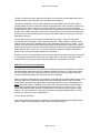
You do need to tell your application software what ports the various devices are on. A utility
called ShowDevices will summarize this information for you and even let you copy the information
and print it. Just connect the AstroHub and run the program. Here is a sample output:
Almost all of the special control boxes you are currently using can be eliminated. Examples of
what can be eliminated are the RoboFocus control unit, the True Tech Filter wheel controller, any
FLI in line box, etc. If you are using a parallel port CCD camera you will have to connect this
directly bypassing the AstroHub as parallel port devices are not supported. Use of a Starlight
Xpress camera with external USB box is accomplished by connecting the USB box to one of the
downstream USB ports on the AstroHub and the other cable from the USB box to the camera.
Page 22 of 33
AstroHub™ User's Guide
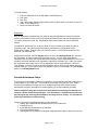
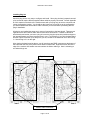
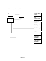
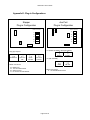
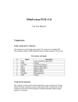
Here is a typical system without an AstroHub:
PC
SXV-H9 Imaging
Camera
COM PORT
USB
PORT
Starlight
USB
Unit
USB HUB
MX5
Guider Camera
TELESCOPE
MOUNT
RS-232 (Go To)
U2S
Relay Box or
STAR2000
Auto-Guide Input
U2S
PCFocus
JMI Focuser
U2S
RoboFocus
Controller
U2S
True Tech FW
Controller
* U2S = USB to Serial
Adapter
Page 23 of 33
RoboFocus
Mechanism
(SCT Focus knob)
True Tech FW
Mechanism
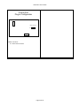
AstroHub™ User's Guide
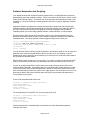
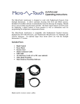
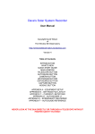
Here is the same system with an AstroHub:
PC
AstroHub
SXV-H9 Imaging
Camera
Starlight
USB
Unit
MX5
Guider Camera
TELESCOPE
MOUNT
RS-232 (Go To)
Auto-Guide Input
JMI Focuser
RoboFocus
Mechanism
(SCT Focus knob)
True Tech FW
Mechanism
Page 24 of 33
AstroHub™ User's Guide
Software Automation and Scripting
Your AstroHub comes with a powerful software module which is a COM (Microsoft Component
Object Model) object with multiple interfaces. There is an interface for the Mount, Guider, Control
Port(s), and Telescope Status. The details of all of the properties and methods are shown in the
Appendix A. Use of the interfaces is called automation and can be a part of application software
or scripts.
Application software developers are including native AstroHub support into their commercially
available software to further take advantage of the enhanced features in the AstroHub. Without
the use of the automation interface your AstroHub is still fully compatible with all software
available whether it is commercially available software, custom software, or custom scripts.
Scripting with the AstroHub can bring significant function to your system operation using the
AstroHub automation module provided. Some example scripts were installed in the AstroHub
installation folder. Here is an example of how to toggle the relay on the control port:
set cp = CreateObject("Astro_Hub.ControlPort")
cp.OpenPort(the port number goes here)
if cp.Relay then cp.Relay = FALSE else cp.Relay = TRUE
cp.ClosePort
set cp = Nothing
You can find this and the following scripts as samples in the AstroHub folder or you can copy and
paste the above text into Notepad and save the file as relay.vbs on your desktop. Use the
ShowDevices utility to determine what COM port your control port is on and insert that number in
the cp.OpenPort command above.
Double click the relay.vbs file icon to run the script. If you have a control port card and the USB
cable is connected to you AstroHub you should hear the relay click each time the script is run.
You can do a similar thing with the mount power control relay using a property of the mount
interface called PowerState. PowerState takes into consideration the jumper settings you made
for the mount power relay contacts and physically connects or disconnects power to the mount.
Here it would be handy to have two scripts, one to apply power to the mount and one to turn it off.
Note that the Mount and Guider interfaces have auto-open functions which will determine the
correct COM port and open it.
Create a file called MountON.vbs like this:
set mount = CreateObject("Astro_Hub.Mount")
mount.AutoOpenBlind
mount.PowerState = TRUE
mount.ClosePort
set mount = Nothing
The corresponding file, MountOFF.vbs, for turning the power off is:
set mount = CreateObject("Astro_Hub.Mount")
mount.AutoOpenBlind
mount.PowerState = FALSE
mount.ClosePort
set mount = Nothing
Consult Appendix A for a detailed listing of all interfaces and their associated properties,
methods, and events.
Page 25 of 33
AstroHub™ User's Guide
Use with ASCOM
While the AstroHub works with any commercial software including any that does not support
ASCOM, some of the advanced features are only available in an ASCOM environment.
For example, ASCOM Telescope drivers have methods to Park and Unpark the telescope mount.
With the AstroHub hardware and the supplied ASCOM telescope hub, astrohub.exe, you can
optionally have the mount power turned on or off automatically when the scope is Unparked or
Parked, respectively. You must use astrohub.exe as the telescope hub for this function to work.
As commercial software that implement an ASCOM telescope hub such as Astronomer's Control
Panel™ or Maxim DL/MaxPoint™ incorporate the features that are in astrohub.exe, the need to
use astrohub.exe as the main telescope hub will be eliminated. Until then, your setup will
effectively have two telescope hubs since astrohub.exe is required.
Note: astrohub.exe exposes an additional property called Telescope.PowerState that is the same
as the Mount.PowerState property and can be used with only the telescope hub and not the
provided AstroHub automation mount interface and example script to toggle the mount power via
the telescope hub is:
Dim x
set t = CreateObject("AstroHub.Telescope")
x = t.PowerState
Wscript.echo("PowerState is currently: " & CStr(x))
if x then t.PowerState = FALSE else t.PowerState = TRUE
set t = Nothing
Note that there is no underscore in "AstroHub" above. This is because the astrohub.exe ASCOM
hub includes a telescope interface. The astro_hub.ocx software automation interface is named
"astro_hub" (with the underscore) to distinguish it from the hub interface.
Appendix A describes the multiple automation interfaces available that can be used in conjunction
with ASCOM software or scripts.
Page 26 of 33
AstroHub™ User's Guide
Appendix A - Automation Interfaces
The automation interfaces for the AstroHub are included in the file astro_hub.ocx which was
installed and registered when the AstroHub software was installed.
The specification document for this is:
AstroHub Automation Interface.pdf
Click the link to open the document if viewing from a PDF file. The above file is located in your
AstroHub installation folder and on the installation CD.
Page 27 of 33
AstroHub™ User's Guide
Appendix B - COM Port Reconfiguration
When the AstroHub hardware was installed and appeared in the Windows Device Manager, COM
Port numbers were assigned by Windows that may be too high for existing software to deal with.
For example, many Visual Basic programs can only support 16 COM ports.
The USB to serial adapters that are used in many places in the AstroHub have software drivers
that can be used to change the COM Port number. To do this you can
Open the Device Manager, expand the Ports section, and make changes there.
Connect the AstroHub via USB to the PC. All of the virtual COM ports will be displayed in the
Device Manager with the COM port number shown.
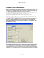
For any port you wish to change, right click on the port listing and select Properties. Select the
Port Settings tab and click the Advanced button. A dialog will appear with a drop down box
showing which COM ports you may use and which are already in use for another device. Note
that COM16 below is "in use".
In many cases, the COM port you wish to use is already in use and may be used by a device that
was previously installed and no longer used or could be used at a high COM port number. Note
that "in use" does not mean that the COM port is open; it means the number was allocated to
another device that may or may not be installed at the time. A good example is a USB to serial
adapter that is not connected now but when it is connected will assume the COM port allocated to
it.
Page 28 of 33
AstroHub™ User's Guide
Com Port number assignments are stored in this registry key (for other than Windows 98):
HKEY_LOCAL_MACHINE\SYSTEM\CurrentControlSet\Control\COM Name Arbiter
in a binary value called ComDB. Deleting the ComDB entry will reset all allocated COM PORT
numbers.
Prior to deleting the ComDB value you should connect your AstroHub and go to Device Manager
and uninstall every Aquest entry in the Ports section. Do this by right-clicking and selecting
Uninstall. Disconnect the AstroHub. Then plug your USB to serial adapters in and uninstall them
in the Device manager as well. If there are any other USB or other pluggable devices that install
as COM ports you should attach them and uninstall them as well. Now delete the ComDB value.
Reconnect the AstroHub and it will go through enumeration and installation process using the
lowest COM port numbers available. You can adjust port assignments as described above but do
it before you reinstall and other COM port devices.
Page 29 of 33
AstroHub™ User's Guide
Appendix C - Connector Pin-outs
Port1/Port2 Plug-in Connectors
DB9
Pin
1
2
3
4
5
6
7
8
9
RS-232
RoboFocus
CD
RX (in)
TX (out)
DTR
GND
DSR
RTS
CTS
RI
COIL1 +
COIL1 COIL2 +
COIL2 +12V
TEMP
GND
True Tech
FW
GND
INDEX
COIL1 COIL1 +
+12V
HOME
LED ON
COIL2 COIL2 +
FLI
Devices
COIL1 +
COIL1 COIL2 +
COIL2 +5V
HOME
GND
Optec
Focuser
GND
+12V
TEMP
+5
COIL1 +
COIL1 COIL2 +
COIL2 -
Control
Port
OUT1
OUT2
OUT3
OUT4
IN1
IN2
IN3
IN4
GND
Misc. Port Plug-in Connector
DB9
Pin
1
2
3
4
5
6
7
8
9
Stepper
Control Port
SW1-1
GND
SW2-1
SW1-2
GND
SW2-2
GND
+5V
+12V
NC-1
COM-1
NO-1
NC-2
COM-2
NO-2
GND
+5V
+12V
Filter Wheel Connector
(from Aux Port Plug-in)
RJ-11
Pin
1
2
3
4
Filter
Wheel
GND
+12V
PULSE
Note: SW1-1 is switch 1 on plug-in 1
SW2-1 is switch 2 on plug-in 1
NC-1 is the relay normally closed contact on plug-in 1
etc.
AstroHub
Connector
1234
Page 30 of 33
Telephone
Handset
Connector
DB9
Pin
1
2
3
4
5
6
7
8
9
AstroHub™ User's Guide
Guider Connector
RJ-11
Pin
1
2
3
4
5
6
AstroHub
Connector
Guider
East
North
South
West
Common*
123456
* AstroHub Common is auto-switched:
GND - "ST-4"/LX-200 compatible
+5V - Older Gemini compatible
PCFocus Connector
RJ-11
Pin
1
2
3
4
5
6
PCFocus
Motor +
Encoder (DSR)
+5V
Encoder (CTS)
GND
Motor -
AstroHub
Connector
123456
Power Connectors (all)
TIP = + plus
RING = - minus
SIZE = 2.1mm I.D. 5.5mm O.D.
Page 31 of 33
AstroHub™ User's Guide
Appendix D- Plug-in Configurations
Aux Port
Plug-in Configuration
Stepper
Plug-in Configuration
Ribbon Connectors
Ribbon Connectors
J1
J1
J12
J2
J2
J4
J11
J4
J6
J6
J7
J7
J9
J9 (Type) Jumpers:
o o
[] []
RoboFocus
o []
[] o
True Tech
FW
[] o
o []
Optec
Focuser
[] []
o o
FLI FW or
Focuser
J11 (Enable for SBIG or Homeyer Wheels):
o
[]
[]
o
Disable
Enable
J12 (RS-232/USB):
o o
[] []
USB
Ribbon Connectors:
J2:
J4:
J6:
J7:
RoboFocus
True Tech Filter Wheel
Optec Focuser
FLI Focuser of Filter Wheels
[] []
o o
RS-232
Ribbon Connectors:
J1: Aux Serial/USB Connector
Page 32 of 33
AstroHub™ User's Guide
Control Port
Plug-in Configuration
Ribbon Connector
J9
Ribbon Connector:
J9: Control Port Connector
Page 33 of 33