1
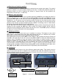
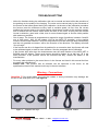
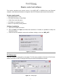
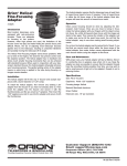
USER’S MANUAL
ASCOM COMPATIBLE
TABLE OF CONTENTS
INSTALLATION ......................................................................................................................................................... - 3 Mechanics - Schmidt-Cassegrain ............................................................................................................................... - 3 Mechanics - Newton ................................................................................................................................................... - 3 Electronics .................................................................................................................................................................. - 3 Introduction ................................................................................................................................................................. - 3 Keys............................................................................................................................................................................ - 3 CONTROLLER AND COMMANDS...........................................................................................................................- 4 Figure 1 Rotary switch
Figure 2 Controller keyboard .................................................................................. - 4 Figure 3 Menu device select
Figure 4 Menu manual position
Figure 5 Menu temperature .................. - 4 Controller options ….. ............................................................................................................................................. - 5 Focuser options ……............................................................................................................................................... - 5 A) Absolute and relative position ............................................................................................................................ - 6 B ) Manual mode operating ....................................................................................................................................... - 6 C) Memory positions … ............................................................................................................................................ - 6 D) Calibration …………. ............................................................................................................................................ - 6 TROUBLESHOOTING ............................................................................................................................................... - 7 Figure 7 Adapters and rings
Figure 8 Cables
Figure 9 Installation .................................................... - 7 REMOTE CONTROL AND SOFTWARE ................................................................................................................... - 8 System requirements .................................................................................................................................................. - 8 Software installation.................................................................................................................................................... - 8 The Setup page .......................................................................................................................................................... - 8 Figure 10 Setup page… ........................................................................................................................................... - 8 Options ....................................................................................................................................................................... - 9 Backlash ..................................................................................................................................................................... - 9 Connect ...................................................................................................................................................................... - 9 Table 1 Description of RS232 communication ports................................................................................................ - 9 The Control page ........................................................................................................................................................ - 9 Figure 11 Control page ............................................................................................................................................ - 9 Position ..................................................................................................................................................................... - 10 Steps ........................................................................................................................................................................ - 10 Defined positions ...................................................................................................................................................... - 10 Saving and opening Position Files ............................................................................................................................ - 10 Figure 12 Window “Defined positions” ................................................................................................................ - 10 Temp. ....................................................................................................................................................................... - 10 NOTES ..................................................................................................................................................................... - 11 NOTES ..................................................................................................................................................................... - 12 Figure 13 Connectors schematic ......................................................................................................................... - 13 TECHNICAL SPECIFICATIONS .............................................................................................................................. - 14 Focuser ..................................................................................................................................................................... - 14 Controller……………. ............................................................................................................................................... - 14 Power supply (optional) ............................................................................................................................................ - 14 -
-2-
INSTALLATION
Mechanics - Schmidt-Cassegrain
The Micro Focuser Digital_NET (MFD_NET) is designed to be compatible with most SchmidtCassegrain telescopes and other mounts with a standard 2 inches barrel (not BIG35 Digital_Net,
subsequently appointed BIG35N). The threaded ring (figure 7), must be removed by hand from
the focuser and attached firmly to the telescope, then connect the MFD_NET focuser rotating it if
needed and block it using the three thumbscrews near the base of the focuser. Along with the
MFD_NET two adapters are supplied (figure 7), the first permits to insert eyepieces and
accessories with a diameter of 1¼”, the seconds is designed for 2” accessories. The available
travel of the focuser is approx. 20 mm (10 mm for the upgrade of the MFD_PC). The positions
displayed on the hand controller are referred to the true steps of the stepper motor, 1000 steps
correspond to 1,000427 mm ( one steps is 0.001000427 mm or a 0,000039387 inches ).
Mechanics – Newton & BIG35N
This focuser supports the same accessories of the Schmidt-Cassegrain model. To mount the
focuser to the telescope use the supplied plate attaching it with screws at the same place of the
previous focuser of the telescope. Before mounting the MFD_NET it is mandatory to securely
attach the plate to the base of the focuser using the 4 thumbscrews supplied. The available
travel of the focuser is approx. 40 or 60 mm.
Electronics
The MFD_NET or BIG35N are a network system which is composed of two or more units
(Digital_Net also with the BIG35N model). The first unit is the control box (“controller”, which
can control up to 10 focusers, for Newton and Schmidt-Cassegrain telescopes). The other units
are the focusers. This network allows to control many focuser in a independent (multitasking)
way, using just one control box and one software. For example, it is possible to focus the main
telescope and the guide telescope at the same time MFD_NET or BIG35N.
The MFD_NET comes with a cable for the 12Vcc power supply (12÷14,5 Vcc allowed range).
Optionally it’s available a power supply with an universal input (110/240 Vac 50/60 Hz) and 12
Vcc output. The 4-pins NET cable between the controller and the focuser is approx. 5 meters
long (from each focuser it’s possible to connect other 4-pins NET cables to control other
devices). The maximum length of the NET cable is 1 Km. The RS232 6-pins cable is 3 meters
long (maximum length: 15 mt, see figure 8) and must be connected between the controller and
the PC, using the DB9 adapter. We recommend to connect the all the cables before turning on
the MFD_NET. If a different power supply is used then it’s mandatory to verify the following
specifications: Minimum Vcc:. 12 Volts, maximum. 14,5 V. At least 1,25 Ampere for the current.
Introduction
The options and command of the MFD_NET or BIG35N are configurable via a “menu” system,
very easy to use. These options are divided in controller and focuser(s). A detailed description
about each menu is available below, section: CONTROLLER AND COMMANDS. Before modifying
any option please read with care the documentation available in this manual.
Keys
Four keys on the controller permit to operate and configure the MFD_NET or BIG35N:
IN, OUT, ENT and ESC. When in this manual they are printed in bold it means that these keys
should be pressed to perform the operation. Do not press more than one key at the same time,
all the commands require just a single click.
-3-
CONTROLLER AND COMMANDS
I. ID configuration: Before powering on the MFD_NET or BIG35N, select the ID number 1 on
the rotary switch (figure 1) located on every focuser. If more than one
identical focuser is connected to the controller, then the other devices
must be set with an increasing ID number (2, 3, 4, etc). This procedure
is not needed if the focusers are different. Example: if two focusers are
connected, the first is a Newton the second a Schmidt-Cassegrain,
they must be set both at ID position 1. If instead the focusers are
identical (example: two Newtons) then the first must be set to position
1, the last to position 2. The controller must be always connected to the
focuser with ID 1.
II. Power on: Connect the power cable to the focuser to turn it on.
Figure 1 - Rotary switch
III. Power off:
Remove the power cable. Powering off the focuser does not delete any internal
setting nor the stored positions.
IV. Device selection:
V.
After powering on the MFD_NET or BIG35N the buzzer will play a short
beep and the writing “Select device” will be shown on the display. After two seconds it will be
possible to choose which focuser has to be controlled, if more than one focuser is connected
(see figure 3). In this case use the keys IN and OUT to choose the focuser and press ENT to
confirm. Press ESC to return to the device selection menu where keeping ESC pressed for
one second it will be executed the function device search to search the network and verify all
connections.
Controller options: Using the controller (figure 2) it’s possible to
configure all the options of the MFD_NET. The options are
grouped in two sets: the first are related to the controller, the
second to the focuser to be controlled. The controller options are
general and related to all focusers, these are: language, speed
(keyboard response), contrast, temperature, buzzer, position.
To modify these settings keep pressed ENT for two seconds then
press IN or OUT to choose the option. Press ENT to select the
option, then IN and OUT to set the desiderated value. To confirm
the new setting press ENT to save it and ESC to exit from the
options menu. The procedure to modify the focuser settings are
just the same: to enter into the focuser menu press ESC for two
seconds instead of ENT. The options for the focuser are:
calibration, reset, minimum speed, maximum speed, backlash.
Figure 2- Controller keyboard
Figure 3 Menu device select
Figure 4 Menu manual position
-4-
Figure 5 Menu temperature
Controller options
The firmware version of the microprocessor will be shown when the menu is displayed.
1.
Language : this option sets the language of the menu, it’s possible to choose: English,
Italian, French and German. Press ENT to enter, IN and OUT to choose, ENT to confirm.
2.
Speed : This is the delay to switch from the minimum speed to the maximum speed when
the keys are pressed to move the focuser. Press ENT to enter, IN and OUT to choose
(minimum 2 seconds, maximum 25 seconds), ENT to confirm.
3.
Contrast : this command sets the contrast of the display, useful then the external
temperature is low. Press ENT to enter, IN and OUT to choose (minimum 20, maximum
186), ENT to confirm.
4.
Temperature : this option selects the scale for the temperature, Degrees or Fahrenheit.
Press ENT to enter, IN and OUT to choose, ENT to confirm.
5.
Buzzer : enables or disables the beeps played by the internal buzzer. Press ENT to
enter, IN and OUT to enable/disable.
6.
Position : Sets the visualization of the position as relative, absolute, or both at the same
time. Press ENT to enter, IN and OUT to select between relative, absolute, or both.
Focuser options
The firmware version of the microprocessor will be shown when the menu is displayed.
1.
2.
3.
Voltage : displays the current voltage as supplied by the power supply. This function is
very import to monitor the voltage when an external battery is used or when many
devices are connected to the network.
Calibration : calibrates the focuser to its zero reference (whole tube inside). This
function must be called if the focuser slipped for an excessive load. After the calibration
the focuser will be positioned at the first quarter of its travel (5 mm for the 20 mm
focuser). During the calibration the current step is displayed on the screen, for example
014 / 028, means step 14 out of 28.
Reset : this function resets all the settings to the factory default. Press ENT to enter, IN
and OUT to enable/disable.
4.
Minimum speed : selects the minimum speed of the motor. The valid range is: minimum
20 steps/second, maximum 190 steps/second. Press ENT to enter, IN and OUT to
modify the setting, then ENT to confirm.
5.
6.
Maximum speed : selects the maximum speed of the motor. The valid range is: minimum
200 steps/second, maximum 600 steps/second. Press ENT to enter, IN and OUT to
modify the setting, ENT to confirm.
Back-Lash : this setting compensate the gears clearance, which can cause a delay and
a positioning error when the motor direction is inverted. The optimal setting must be
found by trial and error, and varies from focuser to focuser, The valid range is: minimum
0, maximum 255. Press ENT to enter, IN and OUT to modify the setting, ENT to confirm.
7.
Temperature visualization : after having selected the focuser to be controlled, (pressing
the key ENT), press ENT again to display the temperature (figure 5) only with
temperature probe (optional).
-5-
A) Absolute and relative position
The absolute position is a number referred to mechanical zero (whole tube inside). The relative
position is referred to a given position chosen by the user. To select this reference follow the
procedure below, be sure to operate the focuser in manual mode. All the positions are
expressed in microns (µm = 1/1000 mm).
B) Manual mode operating
After having selected the focuser to be controlled pressing the ENT key, the display will show on
the first row the focuser model (on the left) and the letter M (on the right) (see figure 4). At this
point press ENT again: on the first row it will be displayed the focuser model and the current
temperature, on the second row the absolute position followed by the letter A which means
“absolute position”. After this data, in the middle of the row the letter I or O will mark the last
direction of the focuser (I stands for IN, O stands for OUT). If a blinking cursor is visible below
the number this means that the focuser is still moving.
On the right side of the second row it’s displayed the relative position, followed by the letter R.
Pressing for two seconds the ENT key, after a beep, the current position will be used as
reference and the displayed relative position will be set to zero. Press ESC quickly to manage
the Memory Positions discussed in the next paragraph.
C) Memory positions
The MFD_NET or BIG35N can store up to 6 positions in memory. This feature is very useful
when using a filter wheel since every filter may change the focus in a different way; another
advantage is the quick refocus when changing different cameras.
After selecting the focuser pressing ENT, on the display it will be shown the focuser model and
letter M on the right side of the row. Use the keys IN and OUT to select the desired memory
position: now it is possible to move the focuser to that position or modify its value. The total
positions available are 6. Press ENT to edit the current position, then press IN and OUT to
modify its value. Press ENT again to move automatically the focuser to that position, at the end
of the procedure a beep will played by the buzzer. To store in memory the current position of the
focuser set the controller to manual mode pressing OUT until the letter M becomes visible, then
press ENT and IN / OUT to find the best focus as reported by the instrumentation.
D) Calibration
This function sets the focuser to its zero reference (whole tube inside). This function must be
called if the focuser was hit or it slipped for an excessive load. After the calibration the focuser
will be positioned at the first quarter of its travel (5 mm for the 20 mm focuser, the display will
show the number 5000 as absolute position).
Temperature probe
Controller
Focuser
NET cable - 4 pins
To the PC through the DB9
adapter and the 6-pins
serial cable
Pow er supply
11 ÷ 14,5 Vcc
Figure 6 - Connection schematics
-6-
Serial port
TROUBLESHOOTING
•
•
•
•
•
•
Noise for vibrations during the calibration: this can be normal and won’t affect the precision of
the pointing nor the quality of the imaging. The noise can be caused only by the movement of
the focuser at the lowest speed during the calibration. At the start of the calibration procedure
the focuser reset its references moving itself at variable speed. At first, from the current
position the focuser slews to the initial position (whole barrel inside) at the maximum speed,
until it detects the Hall sensor which marks the limit of the travel. At this point the focuser
inverts its direction, goes back a little, then it moves forward again to find the initial position
with maximum precision.
Out of range. The focuser is programmed to respect its range of positions, between 0 and 20
mm of free travel ( 0/40 for the newton, 0/10 for the MFD_PC upgrade), so the position
number will be limited between 0 a 20.000. Beyond this limits the motor will stop automatically
and the only possible movement will be the inversion of the direction. The display will show
“Out of range”.
If the focuser was hit or it slipped from its position for an excessive load, the focuser will need
to be calibrated again to reset its zero reference. See the paragraph about Calibration.
If the focuser slips often then the thumbscrews near the serial number of the MFD_NET or
BIG35N must be tighten. These small screws should be tighten by an half turn, all in the
same direction. If the problem cannot be corrected this way, contact the dealer or the
manufacturer1.
For every other problem in the control box or in the focuser not listed in this manual feel free
to contact the manufacturer1.
Please note. This product and its software can be improved in the future, so the
specifications listed in this manual could vary in the next releases.
Warning - Connections
Attention !!! Be careful when you insert the cables, a wrong connection may damage the
focuser of the serial port of PC. See figure 6.
Figure 7
1
Adapters and rings
Figure 8 Cables
Treviso - ITALY - e-mail : [email protected]
-7-
Remote control and software
This section describes the remote control of the MFD_NET or BIG35N from the Personal
computer, with advanced features to integrate it with CCD cameras and remote observatories.
System requirements
• Microsoft Windows™ ALL
• CPU 486 DX minimum, 8 Mb RAM
• 1 Mb of free hard disk space
• CD-ROM (for installation only)
• Mouse or equivalent pointing device
Software installation
1. Insert the CD-ROM in the drive.
2. Click on Install, click Open and follow the instructions. If needed, It’s possible to modify the
destination folder.
3. At the end of the installation execute the software clicking on the icon: MFD_NET.
Figure 9 Installation
The Setup page
The main window is composed by two pages. The first one is related to the setup of the focuser
and its connection to the PC through the serial port and ASCOM platform chosen.
Figure 10 – Setup page
-8-
Options
These options configure the serial port of the PC for a correct communication with Micro
Focuser, selecting a proper BAUD rate and COM port. It’s also possible to set the program
always in foreground, over other applications also when inactive, selecting the checkbox
“Window in foreground”.
Backlash
This parameter, expressed in micron (0..255) compensates the gears clearance, which may
cause a delay and a small positioning error when the motor direction is inverted. Press the
button Set to store the new value.
Connect
Press this button to connect the software with the MFD_NET or BIG35N. If more than one
focusers are available in the network then a dialog window will permit to select the device to be
used. The dialog window contains a list of all focusers available and their characteristics.
When the connection is active the button “Disconnect” becomes enabled, press it to close the
session. Always use this button to disconnect the focuser and use it in manual mode. Closing
the program will not close the connection and the focuser will remain connected.
COM port
Description
Com 1, Com 2
The standard serial port of most PCs.
Com 3, Com 4
Extra ports available when a PCI/ISA expansion card is used.
Com 5, 6, 7, 8
Extra ports available when a USB<>Serial converter is used. This is
the recommended setup if the PC has not any serial port.
Table 1 – description of RS232 communication ports
Click this icon to start the automatic focuser calibration, (see point 2, section focuser
options).
Click this icon to display a dialog window with some useful information about the focuser
model currently under control and the software version.
Click this icon to start this manual.
The Control page
This page is related to the control of the focuser via the serial port.
Figure 11 – Control page
-9-
Position
This panel displays the current position, both absolute and relative (see paragraph Absolute
and relative positions, page 6). The panel contains also the buttons IN and OUT to move the
focuser by a free amount. On the right side of the pointers a vertical bar that it indicates, in
graphical form, the position of the focuser regarding the zero.
Steps
This panel contains some buttons to move the focuser by a fixed amount of steps. If the focuser
is close to its range limits, then it will only move until the end of its travel.
Defined positions
Here it is possible to choose the visualization mode of the current position, as Absolute or
Relative. Selecting Relative the button Reset ref. will be enabled, pressing it the current
position will be used as a reference for the further positions (new zero reference). Under these
options a combo box permits to select and store some user positions: write with the keyboard a
number (between 1 and 20.000 for the 20mm focuser, zero won’t be accepted) and a name to
describe the position. The absolute positions must be in the range of the focuser and cannot be
negative. The relative positions can be negative, their range depends by the current absolute
position. If the relative value sets the focuser out of its range, then the command will be
accepted but the focuser will obviously stop at the end of its travel.
To move the focuser to the selected position click the button Go or press [ENTER] on the PC
keyboard. Every new position will be stored in the combo box, press the button with the “book”
icon to display a dialog window (see figure 12) where every position can be edited as text file,
saved to disk and loaded.
The correct syntax is: < Position > (Space) < Description >
Example:
3802 Green filter
Note: The space between the position and the description is always required.
Saving and opening Position Files
All positions stored in the combo box can be edited, saved and loaded from the “Defined
position” dialog window (figure 11). Click the “book” button to display the window then use the
buttons on the tool bar to execute the desired command.
Figure 12 – Window “Defined positions”
Temp.
This panel displays the temperature as detected by the external probe. It’s possible to choose
the scale between Degrees and Fahrenheit.
- 10 -
NOTES
- 11 -
NOTES
- 12 -
CABLE AND
SERIAL ADAPTER DESCRIPTION
CONNECTOR
RJ11
DE SCRI PTION
654321
SERIAL CABLE - 6 WAYS
SE RI AL ADAPTER
DB9
1 WHITE
NC
1 NC
2 BLACK
GND
2 BLA CK
3 RE D
NC
3 RED
4 GREE N
RX
4 NC
5 YELLOW
TX
5 YE LLOW
6 BLU
NC
6-7-8-9 NC
FRONTAL VIEW
4321
NET CABLE - 4 WAYS
FRONTAL VIEW
TEMPERATURE PROBE (OPTIONAL)
NET CABLE
DESCRIPTION
1
Y ALLOW
+ 12 V
2
GREEN
A CHANNEL
3
RED
B CHANNEL
4
B LA CK
GND
+
DQ
CONNECTOR
-
PROBE
5
FRONTAL VIEW
9
4
8
FRONTAL VIEW
1
2
3
7
4
5
2
6
6
1
SERIAL ADAPTER DB9
Figure 13 –
Connectors schematic
- 13 -
TECHNICAL SPECIFICATIONS
DIGITAL_NET S/C (20 mm), NW (40 mm) or (60 mm discontinued) – BIG 35 (40 mm)
Focuser
Total travel distance, mm
Total travel distance, mm BIG 35 Net
Precision on reset
Maximum speed
Minimum speed
Motor
Maximum load
Maximum load BIG 35 Net
Pinion (reducer)
Gear (focuser)
Pinion (reducer) BIG 35 Net
Gear (focuser) BIG 35 Net
Controller connector
CPU
Technology
CPU Memory
Ram
EEPROM
Clock frequency
Power consumption (max)
Temperature probe (OPTIONAL)
Size (minimum)
Operating temperature
Calibration sensor
Power supply
Weight
20 (S/C), 40 or 60 (newton)
40
5 µm approx.
600 steps/seconds
1 step/seconds
stepper micro motor Ø 16 mm + reducer 166:1
4,5 ÷ 5,2 kg ( depends by the tilt of the instruments )
18 ÷ 20 kg ( depends by the tilt of the instruments )
15 teeth, INOX steel
71 teeth, brass
28 teeth, INOX steel
53 teeth, brass
Modular Jack 4 pin, golden - cable mt 5,00
RISC, PIC Microchip 16F876i
FLASH / EEPROM
FLASH 8K – 14 bit
368 bytes
256 bytes
16 MHz
650 mA
Digital 9 bit, lin. ± 0,5°C ( -0 / +70 ), cable 50 cm
110 x 92 x 75 mm ( L x W x H )
-25 + 65 °C
Hall effect / neodymium magnet
external 12 ÷ 14,5 Vcc
2,90 approx. (BIG 35 Net) - D_Net 720 gr. (20 mm), 780 gr. (40 mm)
Controller
CPU
Technology
CPU memory
Ram
EEPROM
Clock frequency
Power consumption (max)
Focuser connector
PC connector (serial)
Size (minimum)
Operating temperature
RISC, PIC Microchip 18F252i
FLASH / EEPROM
FLASH 32K – 16 bit
368 bytes
256 bytes
16 MHz
35 mA
Modular Jack 4 pin, golden - cable mt 5,00
Modular Jack 6 pin, golden - cable mt 2,40
105 x 72 x 25,5 mm ( L x W x H )
-25 + 75 °C
Power supply (optional)
Input
Output
Connector
Certificate
100~240 Vac, 47~63 Hz, 0,5 A
12 Vcc, 1,25 A, 15W max.
Coaxial plug 5,5 mm ( +Vcc central pin )
UL - CE - GS – CB
Revision January 2015 - firmware: controller 1.34 – focuser 1.7
web: http://www.microfocuser.com -- e-mail: [email protected]
1999-2015 ©
- 14 -