1
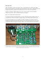
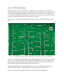
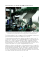
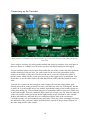
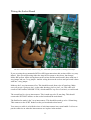
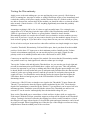
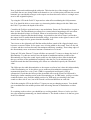
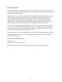
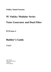
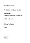
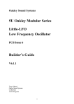
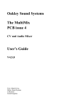
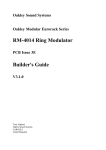
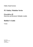
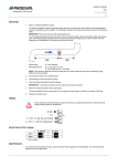
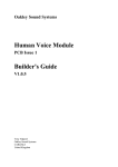
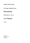
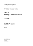
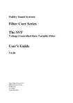
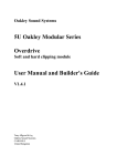
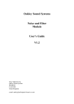
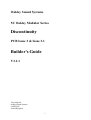
Oakley Sound Systems
5U Oakley Modular Series
Discontinuity
PCB Issue 3 & Issue 3.1
Builder's Guide
V3.1.1
Tony Allgood
Oakley Sound Systems
CARLISLE
United Kingdom
1
Introduction
This is the Builder's Guide for the issues 3 and 3.1 Discontinuity 5U module from Oakley
Sound. In this document you will find a basic introduction to the boards, a full parts list for the
components needed to populate the boards and a list of the various interconnections.
For the User Manual, which contains an overview of the operation of the unit and the
calibration procedure, please visit the main project webpage at:
http://www.oakleysound.com/discon.htm
For general information regarding where to get parts and suggested part numbers please see
our useful Parts Guide at the project webpage or http://www.oakleysound.com/parts.pdf.
For general information on how to build our modules, including circuit board population,
mounting front panel components and making up board interconnects please see our generic
Construction Guide at the project webpage or http://www.oakleysound.com/construct.pdf.
The prototype issue 2 Discontinuity fitted to a natural finish Schaeffer panel in the MOTM format. Issue 3
is almost identical. Note the use of the optional pot and socket boards to make the wiring up of the many
sockets, switches and pots much easier.
2
The Issue 3 and Issue 3.1 Discontinuity PCB set
The main printed circuit board (PCB) is 113 mm (depth) x 143 mm (height) in size. All three
boards use double sided copper traces and have through plated holes. The solder pads are
large and are easy to solder and de-solder if necessary. They have a high quality solder mask
on both sides for easier soldering, and have clear legending on the component side.
If you are building the standard design there are no components mounted off the boards
except for the switches and LED. All other components including sockets and pots are
soldered directly to the boards.
Prior to 2004 many Oakley modules had the sockets, switches and extra pots wired to the
board by individual wires. This module allows all the socket wiring to be done via the socket
PCB and three MTA solderless or Molex connections. If you are building this module in the
standard Oakley format this new system will reduce assembly time and possible wiring errors.
Some people will wish to use this Oakley design in a non standard format, such as fitting it to
another manufacturer’s rack or one of their own invention. This is perfectly easy to do. Simply
do not use the socket board and wire the main board to the sockets as per usual. I have laid
the board out to accept 0.1” headers for each additional pot and switch.
I have provided space for four of the control pots on the main PCB, whilst the other four pots
are fitted to their own board. If you use the specified pots and brackets, the PCBs can be held
firmly to the panel without any additional mounting procedures. The pot spacing is 1.625” and
is the same as vertical spacing of the MOTM modular synthesiser.
The first run of issue 3 Discontinuity boards have a tracking error which was corrected with
the release of issue 3.1. In the earlier issue 3 boards the positive power supply to the
comparator, U2, and associating decoupling capacitor is connected to the +5V and not the
+15V as required. Before using an issue 3 module the PCB must be first modified. A track
needs to be cut and a small strapping lead fitted. This is a relatively simple job and it can be
done neatly enough so that the overall appearance of the module is not detrimentally affected.
The details of this modification are given later in this document. Once modified an issue 3
board will behave identically to an issue 3.1.
The whole project takes around 3 to 4 hours to build and test.
3
Discontinuity issue 3 and issue 3.1 Parts List
For general information regarding where to get parts and suggested part numbers please see
our useful Parts Guide at the project webpage or http://www.oakleysound.com/parts.pdf.
The components are grouped into values, the order of the component names is of no particular
consequence.
A quick note on European part descriptions. R is shorthand for ohm. K is shorthand for kiloohm. R is shorthand for ohm. So 22R is 22 ohm, 1K5 is 1,500 ohms or 1.5 kilohms. For
capacitors: 1uF = one microfarad = 1000nF = one thousand nanofarad.
To prevent loss of the small ‘.’ as the decimal point, a convention of inserting the unit in its
place is used. eg. 4R7 is a 4.7 ohm, 4K7 is a 4700 ohm resistor, 6n8 is a 6.8 nF capacitor.
Resistors
All resistors, except were stated, are 5% carbon 1/4W although 1% metal film types are
recommended.
Components designated as 1% should be 0.25W 1% metal film or better.
22R
47R
150R
330R
1K
1K5
2K2
4K7
6K8
10K, 1% metal film
10K
15K
22K
24K
47K
68K
82K
100K
150K
330K
390K
1M
R13, R26, R46
R50
R7, R25, R84
R69, R68, R67, R70
R52, R45, R44, R79
R3, R23, R24
R17, R41, R38
R27, R47
R10, R22
R78, R77, R75, R76
R5, R9, R21, R57, R74
R73, R39, R64, R51
R2, R14, R36, R1, R65, R42, R71, R43, R34, R32, R53
R16, R40
R28, R4, R81, R12, R11, R30, R29, R31, R61, R63,
R59, R60, R58, R62, R56, R55
R20, R83
R37, R15, R54
R48, R49, R18, R19, R33, R35
R82
R80
R72, R66
R8, R6
4
Capacitors
12pF or 15pF 2.5mm C0G ceramic
33pF 2.5mm C0G ceramic
100pF 2.5mm C0G ceramic
C24
C5, C15, C25
C1, C31
100nF, 63V multilayer axial ceramic C9, C2, C14, C20, C21, C17, C19, C11, C4, C3, C18,
C26, C10, C16, C30, C27, C8
2u2, 63V electrolytic
33uF, 35V electrolytic
47uF, 35V electrolytic
C22, C23, C28, C29
C13, C6, C7
C12
Discrete Semiconductors
1N4148 signal diode
5V1 zener diode
1N5819 Schottky diode
BC560 PNP transistor
5mm red/green bi-colour LED
D9, D7, D8, D2, D1, D12, D3, D4, D5, D6, D13, D14,
D15, D16
D11, D10
D17, D18
Q1, Q3
LED
Integrated Circuits
4558 dual bi-polar op-amp
U1
78L05 +5V 100mA regulator
U14
79L05 -5V 100mA regulator
U15
TL072 dual J-FET op-amp
U3, U4, U5, U6, U9, U10, U12, U13
LF412CN dual J-FET op-amp
U7
DG403 dual SPDT analogue switch U8
LM13700 dual OTA
U11
LM2903 dual low power comparator U2
IC sockets are to be recommended. You need ten 8-pin and two 16-pin DIL sockets.
Trimmers (preset) resistors
100K, 6mm cermet trimmer
100K multiturn cermet trimmer
OFF1, OFF2
ZERO, UNITY
5
Pots (Main board)
47K or 50K linear 16mm Alpha
Three pot brackets
DISCON, VOLUME, FOLD, THRESH
Pots (Pot board)
47K or 50K linear 16mm Alpha
Three pot brackets
DIS CV, OFFSET, FLD CV, THR CV
Miscellaneous
Ferrite bead axial
L2, L1
6-way 0.1” (2.54mm) jumper
4-way 0.1” (2.54mm) jumper
OFF/TRK, CVD/POL ie. 2 off
CVF/CVT ie. 1 off
MTA156 4 way header
MTA100 6-way header
PSU – Oakley/MOTM power supply
PWR – Synthesizers.com power supply
0.1” 2-way header
0.1” 3-way header
0.1” 4-way header
0.1” 5-way header
LED – Optional LED wiring method.
SCKT (pot board), SCKT (socket board)
SKT-BOT (main board), SKT-BOT (socket board)
SKT-TOP (main board), SKT-TOP (socket board)
0.1” 2-way housing
0.1” 3-way housing
0.1” 4-way housing
0.1” 5-way housing
LED – Optional LED wiring method.
SCKT (pot board), SCKT (socket board)
SKT-BOT (main board), SKT-BOT (socket board)
SKT-TOP (main board), SKT-TOP (socket board)
Hook up wire to suit connectors
Uninsulated tinned copper wire
2 metres
6 off 60mm pieces for wiring the switches
Other panel components
Clear LED lens clip & securing ring
SPDT On-On switch
SPDT On-Off-On switch
1/4” Switchcraft 112APC sockets
Knobs
LED
TRK/OPP
POS/NEG
Eight sockets
Eight to suit
6
– see 'Connections'
– see 'Connections'
Issue 3 PCB Modifications
On the first run of issue 3 boards there is a tracking error. A tracking error is where the
copper connections on the PCB have been placed incorrectly. In this case the positive supply
to U2 and its associating decoupling capacitor has been connected to the +5V and not the
+15V. Thus you will need to cut this track, to make sure the erroneous connection is broken,
and then correctly connect pin 8 of U2 to the positive supply.
The track to be cut is on the underside and the job can be done with all the components in
place.
A close up of the underside of the issue 3 board. Issue 3.1 boards do not need to be modified.
As can seen in the photograph the thick track connecting pin 8 of U2 and the bottom of R10
has been cut. I tend to cut track with a sharp knife in two places close to one another. Then
with my soldering iron I gently heat the orphaned sectioned in between the two cuts. This
loosens the glue and the unwanted track section will slide off.
Then with a small length of insulated solid core wire – I use 0.25mm Kynar wire but any
suitable wire may be used – connect pin 8 of U2 with the lower solder pad of R13.
Later runs of the board, starting with issue 3.1, will not need this modification.
7
Building the Oakley Discontinuity
General details on building Oakley modules are given in the Construction Guide. However,
there is also some additional information later in this Builder's Guide.
I suggest if using the optional pot and socket boards that the module be built in this order:
1. Populate the socket board using the front panel as a former to hold the sockets as you
solder them. Fit the socket board to the panel.
2. Solder the SCKT header and pots to the pot board. Don't solder the pot brackets just yet.
3. Attach the pot board to the panel and solder the pot brackets on the pot board. Do not
solder the switches at this stage. Remove the pot board from the panel.
4. Populate the main board if not already done so.
5. Solder the pots, but not their brackets, to the main board ensuring that the pots are at right
angles
6. Fit the main board to the panel and solder the pot brackets.
7. Solder the LED and solder in the flexible jumpers if you are using them.
9. Refit the pot board and solder the other ends of the jumpers.
10. Fit the switches and solder them into the pot board with short lengths of wire.
11. Make and fit the socket board interconnects.
12. Test and calibrate.
8
The LED and the Pot Board to Main Board Interconnects
Close up of the pot board to main board interconnects and the LED connection. Here I have used my
usual method of a two way Molex KK to attach the LED to two fly wires from the main board.
The first thing that should be done is to connect the LED to the main board. Keep your wires
short so that the board jumper from OFF/TRK does not get impeded.
The interconnections between the pot and main board can be done in a variety of ways. You
can either use 0.1” headers and wires or use flexible jumpers. There are three interconnects to
make up, two 2” (50mm) 6-way jumpers and one 2” (50mm) 4-way jumper. To do this
cheaply you can purchase a twenty way wide jumper and then carefully cut it down into the
three sections required. I use TE Connectivity's FSN-22A-20 available from Farnell. This is a
very thin flexible strip but you can also the insulated multistrand wire ones too.
I find it best to solder one end of the jumpers in before mounting the boards to the panel. For
Discontinuity module I would suggest that soldering the jumpers to the main board first which
is already attached to the front panel. Then once this is done you can mount the pot board to
the panel while coaxing the other ends of the jumpers into the pot board's holes. Obviously
you need to solder the jumper wires from the top of the pot board. Make sure you trim off any
excess jumper wire with a pair of wire cutters from both boards.
9
Connecting up the Switches
Both switches are wired identically with the switches' lugs connected to the pot board's solder pads directly
below them.
I have tried to avoid any free wiring in this module and wiring up switches is my only lapse in
this area. However, I think I have devised a nice neat way that is both quick and rugged.
Fit your switches in their correct holes. Remember that one of the switches has three positions
and this should go in the top hole. For each switch use the one of the nuts and the spring
washer on the inside of the panel. Use the second nut to secure the switch to the panel. It
doesn’t matter which way the switch goes in so long as the toggle moves up and down. You
do not have to use the other washer, the odd shaped lock washer, that the switch kit comes
with.
Your job is to connect the three tangs on each switch to the currently empty solder pads
directly below them on the pot board. I'm sure you'll find your own way of doing this, but this
is what I do: Lay the module on its side with the main board resting on the bench top and rear
of the panel facing you. Take a 60mm long piece of uninsulated tinned copper wire. Make sure
its nice and straight. Then put a small 90 degree bend in it near the very top. Place the long tail
of the wire into the solder pad on the board, right handed people will want to start with the
furthest left hand hole, and hook the wire's small bend into the hole of the switch tang.
Carefully bend the wire end around the tang and solder. Then snip off the remaining wire from
the underside of the pot board. Solder the pad from the topside of the pot board. Repeat for
the other tangs and the other switch.
10
Wiring the Socket Board
The three socket board interconnects using 0.1” Molex KK system of headers, housings and crimps.
If you are using the recommended MTA or KK interconnections this section will be very easy
indeed. Here you will be using either the Amp MTA system or the slower, but cheaper,
Molex KK system. All the wiring between the sockets and the main board is done with one 4way jumper and one 5-way jumper. And the wiring between the sockets and pot board is done
with one 3-way jumper.
Make up the 5-way interconnect first. This should be made from wires 65 mm long. Make
sure you get pin 1 going to pin 1 on the other housing, pin 2 to pin 2, etc. This cable will
connect to the headers called SKT-TOP, which stands for 'top row of sockets', on each board.
The second lead is a 4-way interconnect. This is made up to be 95 mm long. This should
connect the SKT-BOT headers on the socket board and the main board.
The final lead to make is the 3-way interconnect. This should be made up to be 130mm long.
This connects to the SCKT headers on the pot board and socket board.
You can use a cable tie to hold the wires of each interconnect into a neat bundle. It is best to
put the cable ties on when the interconnects are in place in the module.
11
Building the Discontinuity without the Pot and Socket Boards
Your job will be that much harder without the pot and socket boards. However, the
Discontinuity main board has been designed so it can be used without the other optional
boards. I'm not going to a large amount of detail here since I am not able to predict how you
are wanting to wire your module together. However, I will offer some hints that hopefully will
prove useful to you.
If you have bought Switchcraft 112A sockets you will see that they have three connections.
One is the earth or ground tag. One is the signal tag which will be connected to the tip of the
jack plug when it is inserted. The third tag is the normalised tag, or NC (normally closed) tag.
The NC tag is internally connected to the signal tag when a jack is not connected. This
connection is automatically broken when you insert a jack.
It is advisable to mount the sockets to the panel first and wire these to the main board. Then
you should ground the earth lugs on each socket. Do this by joining the earth lugs of each
horizontal row of sockets together with stiff single core wire. There is no need to join the two
horizontal wires together at this stage. Now with a single piece of insulated wire connect the
top grounding wire to pin 2 of the header SKT-TOP. Pin 1 is depicted by the square pad.
Then connect the bottom grounding wire back to the main board's SKT-BOT header at pin 4.
Pin 1 on SKT-TOP and pin 4 of SKT-BOT are connected together on the main board and thus
to the earth/panel connection, via pin 3 of the PSU header, at the power supply.
It is also advisable to ground the NC lugs of the three input sockets too. Do this in the same
way you have commoned the earth lugs. Simply connect the THRESH, FOLD and DISCON
sockets' NC lugs with a piece of stiff wire. Then with a piece of insulated wire connect them
back to pin 3 of SKT-BOT. Note that pin 3 of SKT-BOT is module ground and is not
connected to the earth/panel on the main board. These two types of ground are connected
only at the power supply in an Oakley modular system.
The connections of the signal lugs of the CV and audio output sockets that go directly to the
PCB are summarised below:
SKT-TOP
Pin
Pad name
Socket Name
Lug Type
Pin 1
Pin 2
Pin 3
Pin 4
Pin 5
INPUT
Panel ground
OUTPUT
CLIP-OUT
CLAMP-OUT
INPUT
Top row sockets
OUTPUT
CLIP
CLAMP
Signal
Ground
Signal
Signal
Signal
12
SKT-BOT
Pin
Pad name
Socket Name
Lug Type
Pin 1
Pin 2
Pin 3
Pin 4
OFFSET_CV
OFFSET_NC
Module ground
Panel ground
OFFSET
OFFSET
THRESH, FOLD, DISCON
Bottom row sockets
Signal
NC
NC
Ground
There are three sockets, THRESH, FOLD and DISCON, which have yet to have their signal
lugs connected. This is because these signals feed directly to the front panel pots of the same
name.
Each pot and switch has been given its own header on the main board. Some of them are fitted
close together so that the pot board can utilise multiway 0.1” flexible interconnections. It is
also helpful to look at the schematic for the pot board to see how each pot and switch is
connected.
Pots have three pins. Two of these pins will be connected to PCB, whilst the remaining one
will be connected to the appropriate socket's signal lug.
The middle pin of the pot, the wiper, will carry the signal to the appropriate header on the
PCB. This is pin 1 (the square pad) on each of the two way headers, CVT, CVF and CVD for
the THRESHOLD CV, FOLD CV and DISCON CV pots respectively.
Each pot has two other pins, one will be connected to ground, the other to the signal lug on
the socket it controls.
With the pot's pins facing down and looking at the back of the pot, the right hand pin should
go to the ground connection of the header. This is pin 2 on each of the headers, CVT, CVF
and CVD for the THRESHOLD CV, FOLD CV and DISCON CV pots respectively.
Now each of the three input pots will have one unsoldered pin left. Connect each to the
appropriate socket. The wire should go from the pot to the signal lug of the socket.
The OFFSET pot is different. It doesn't have an associating input socket and all three lugs
connect to the main board via the header, OFF. Pin 1 of OFF goes to the right hand pin of the
pot. Pin 2 (the middle one) goes to the middle pin. Pin 3 goes to the left hand pin of the pot.
That's all the pots wired up. Just check that all the pots have all three pins wired up.
There are two switches to do now. Again, like the pots, each switch has three pins or tangs.
All three tangs on each switch are to be connected to the PCB and each switch has it's own
header. The TRK/OPP switch uses the TRK header, while the POS/NEG switch uses the POL
header. Each switch is wired in the same fashion; the top tang of the switch goes to pin 1 of
the header, the middle tang goes to pin 2, and the bottom tang goes to pin 3. Note that the
header POL has an extra pin, pin 4, but we have no need of this.
13
Testing the Discontinuity
Apply power to the unit making sure you are applying the power correctly. Check that no
device is running hot. Any sign of smoke or strange smells turn off the power immediately and
recheck the polarity of the power supply, and the direction of the ICs in their sockets. If you
are able to measure the current taken by the module you should be able to see that the module
takes around +50mA from the +15V rail. Anything significantly more than this probably
indicates a fault.
Assuming everything is OK so far, it is time to apply an audio input. Use a triangle wave
output from a VCO and plug it into the input socket of the Discontinuity module. Middle A,
220Hz is a good note to use. Before we go any further I should re-iterate that the
Discontinuity module is a complex device and it is not as intuitive as other modules you may
have used. If you have a 'scope you may want to hook it up to the module's output to have a
look at what is going on. If you don't have a 'scope then fear not your ears will tell you plenty.
So let us look at each pot in turn and see what affect each has our simple triangle wave input.
Centralise Threshold, Discontinuity, Fold and Offset pots, that is put them all at their middle
position. Set the three CV input pots to their minimum position. Initially put the Volume
control at its minimum setting but you can turn this up once you apply a signal. Set the
polarity switch to its middle position and set the offset mode to track (TRK).
Connect up an amplifier to the output of the module. Be aware that the Discontinuity module
can produce some very loud signal levels when its volume pot is set high.
Turn up the Volume a bit and adjust the Threshold pot. As you turn the pot slowly right and
towards its maximum point you'll initially hear a square wave type tone. This will gradually
become less apparent as you keep on turning and with a little plop the input triangle wave will
be heard. Rotate it slowly backwards, past its mid point and you'll then hear the characteristic
sound of a pulse wave getting narrower until the pot reaches its end point whereupon the
sound will cease. You should also notice that the louder the output signal the brighter the
LED shines. Both red and green parts of the LED should be lit since the output signal is
alternating current.
Connect up a 1Hz LFO sine or triangle wave signal to the Threshold CV input. Rotate the
Thresh CV pot and notice how the output sound is modulated by the LFO. Check that the
depth of the modulation is controlled by the Thresh CV pot and that it can be turned off at its
minimum position. Familiarise yourself with the action of the Threshold pot and how an
external CV can be used to 'automagically' alter the threshold voltage for you.
Now set the Threshold pot to around three o'clock and leave it there while we explore the
Fold control. With the Fold pot central the output waveform will be clipped at the Threshold
voltage. Turning it clockwise will make the clipping less effective and at around two o'clock
the triangle wave input is heard again. Go beyond this point and upper harmonics can be heard
in greater strength. What is happening here is that the tips of the triangle waveform are being
amplified more than the middle parts of the waveform.
14
Now go backwards and through the mid point. This time the tips of the triangle waveform
come back but are now being folded in on themselves. At a certain point you'll hear the second
harmonic get considerably stronger as the output waveform becomes closer to a triangle wave
at twice the original frequency.
Try using the LFO in the Fold CV input and see what affect modulating the fold parameter
has. You should be able to create some very interesting timbre changes with this. Make sure
the Fold CV pot alters the depth of the effect.
Centralise the Fold pot again and remove any modulation. Ensure the Threshold pot is again at
three o'clock. The Discontinuity pot allows us to control what is happening to the waveform
when the threshold voltage is exceeded. When at its mid position it simply allows the
waveform to clipped at the threshold voltage. At positions to the left of centre it will reduce
the output level to smaller than the threshold voltage. At positions to the right of centre it will
increase the output level to greater than the threshold level.
Turn it now to the right and you'll find the mellow hollow sound of the clipped triangle wave
becomes even more hollow as if a square wave is being added to the sound. Turn it to the left
of centre and the waveform becomes discontinuous and buzzy sounding. Those sharp edges of
the discontinuity cause an increased amount of harmonics to be heard.
Using an LFO in the Discon CV input will allow an external CV source to change the level of
Discontinuity. Try this now and see how the depth of modulation and the position of the
Discontinuity pot alters the sound. Again, make sure the depth pot does what it should and
that you can turn off the modulation completely when the pot is at its minimum value. It
should be noted that the Discontinuity pot's affects are controlled in part by the Threshold
value.
The Offset pot also adds discontinuities to the output waveform, but it does this independently
of the Discontinuity pot. It also allows you to make any discontinuities symmetrical or
asymmetrical about zero volts. Track (TRK) is asymmetrical and Oppose (OPP) is
symmetrical. Check that the Offset pot has an audible effect on the sound. In OPP mode it
should give similar sounding results to the Discontinuity pot. In TRK mode, you'll get a richer
sound the further away from the middle position. In TRK mode you should get the same
sound on either side of zero, but in OPP mode it will sound different on each side.
Check that using the LFO in the Offset CV input you can get changing textures. You should
get no modulation in the middle position while increasing amounts of modulation on either
side.
If everything works as above you should have a working module. However, before you fix it
into your modular permanently you should calibrate it. The details on how to do that are given
in the User Manual.
15
Final Comments
If you have any problems with the module, an excellent source of support is the Oakley Sound
Forum at Muffwiggler.com. Paul Darlow and I are on this group, as well as many other users
and builders of Oakley modules.
If you can't get your project to work, then Oakley Sound Systems are able to offer a 'get you
working' service. If you wish to take up this service please e-mail me, Tony Allgood, at my
contact e-mail address found on the website. I can service either fully populated PCBs or
whole modules. You will be charged for all postage costs, any parts used and my time at
25GBP per hour. Most faults can be found and fixed within one hour, and I normally return
modules within a week. The minimum charge is 25GBP plus return postage costs.
If you have a comment about this builder's guide, or have a found a mistake in it, then please
do let me know. But please do not contact me or Paul Darlow directly with questions about
sourcing components or general fault finding. Honestly, we would love to help but we do not
have the time to help everyone individually by e-mail.
Last but not least, can I say a big thank you to all of you who helped and inspired me. Thanks
especially to all those nice people on the Synth-diy and Analogue Heaven mailing lists and
those at Muffwiggler.com.
Tony Allgood at Oakley Sound
Cumbria, UK
© June 2012 – updated August 2013
No part of this document may be copied by whatever means without my permission.
16