1
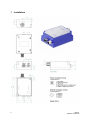
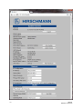
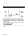
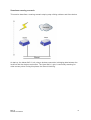
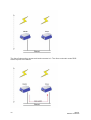
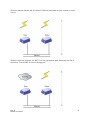
User Manual
Configuration and Administration
Industrial Wireless LAN Client
BAT-C
BAT-C
Release 01 08/2012
Technical Support
https://hirschmann-support.belden.eu.com
The naming of copyrighted trademarks in this manual, even when not specially indicated,
should not be taken to mean that these names may be considered as free in the sense of the
trademark and trade name protection law and hence that they may be freely used by anyone.
© 2012 Hirschmann Automation and Control GmbH
Manuals and software are protected by copyright. All rights reserved. The copying,
reproduction, translation, conversion into any electronic medium or machine scannable form
is not permitted, either in whole or in part. An exception is the preparation of a backup copy
of the software for your own use. For devices with embedded software, the end-user license
agreement on the enclosed CD applies.
The performance features described here are binding only if they have been expressly
agreed when the contract was made. This document was produced by Hirschmann
Automation and Control GmbH according to the best of the company's knowledge.
Hirschmann reserves the right to change the contents of this document without prior notice.
Hirschmann can give no guarantee in respect of the correctness or accuracy of the
information in this document.
Hirschmann can accept no responsibility for damages, resulting from the use of the network
components or the associated operating software. In addition, we refer to the conditions of
use specified in the license contract.
You can get the latest version of this manual on the Internet at the Hirschmann product site
(www.hirschmann.com).
Printed in Germany
Hirschmann Automation and Control GmbH
Stuttgarter Str. 45-51
72654 Neckartenzlingen
Germany
Tel.: +49 1805 141538
2
BAT-C
Release 01 08/2012
Contents
About this Manual
5
1
6
2
Installation
1.1
Power
7
1.2
Ethernet interface
7
1.3
Status indicators
7
General Concepts
9
2.1
Configuration Methods
9
2.2
Using the SMART configuration mode
9
2.3
Using the WEB configuration
10
2.4
Reset to factory defaults
13
2.5
Wireless LAN modes
13
2.6
BAT-C modes
13
2.7
WLAN Security
13
2.7.1
3
Key management
14
Supported Use Cases
16
3.1
Two BAT-C’s Connected as an Ethernet Bridge - Ooption 1
3.1.1
3.2
Two BAT-C’s Connected as an Ethernet Bridge - Option 2
3.2.1
3.3
How to setup this example?
Several Ethernet devices connected in Client mode - Option 1
3.8.1
3.9
How to setup this example?
A PC wirelessly connected to a BAT-C - Option 2
3.7.1
3.8
How to setup this example?
A PC wirelessly connected to a BAT-C - Option 1
3.6.1
3.7
How to setup this example?
Two BAT-C’s Connected in Client mode - Option 2
3.5.1
3.6
How to setup this example?
Two BAT-C’s Connected in Client mode - Option 1
3.4.1
3.5
How to setup this example?
Two BAT-C’s Connected as an Ethernet Bridge - Option 3
3.3.1
3.4
How to setup this example?
How to setup this example?
Several Ethernet devices connected in Client mode - Option 2
3.9.1
How to setup this example?
BAT-C
Release 01 08/2012
16
16
18
18
19
19
19
20
21
21
23
23
25
25
27
27
29
29
3
3.10
One or more BAT-C’s connected to a Wired Infrastructure through WLAN
3.10.1 How to setup this example?
3.11
External WLAN client connected to a BAT-C
3.11.1 How to setup this example?
3.12
Multi-Client mode
3.12.1 How to setup this example?
3.13
A
4
Seamless roaming and redundancy
31
31
33
33
35
35
36
3.13.1 How to setup this example?
42
3.13.2 Limitations
43
Further Support
44
BAT-C
Release 01 08/2012
About this Manual
■
Abstract
This document is a product guide defining the main use cases for Hirschmann BAT-C
Ethernet Port Adapter (later called BAT-C). Furthermore, this document describes how to
configure the device for specific applications. It also contains general information about the
product.
■
Related Documents
BAT-C User Manual Installation. Is a quick setup guide to aid as a quick reference when
setting up the BAT-C for the simplest out-of-the-box applications.
BAT-C CLI-Reference. Detailed specification/reference for the supported AT commands.
BAT-C
Release 01 08/2012
5
1 Installation
6
BAT-C
Release 01 08/2012
1.1 Power
The table below shows typical current at 24 V.
Operation
Mean (mA)
Startup
Max (mA)
58.8
Idle
58.7
58.8
Idle, Ethernet
69
69.1
Idle + 4xMode LEDs
74.2
74.3
Connecting
63.2
63.9
Connected Data
63.2
64.8
Connected, Data, Ethernet
73.4
75.5
Connected, Data, Ethernet, 4xMode LEDs
78.6
80.7
1.2 Ethernet interface
The Ethernet interface supports 10/100 Mbps with both MDI/MDI-X auto crossover and
polarity correction.
1.3 Status indicators
Description
Color
Status
Meaning
P
Green
On
Supply voltage is present and application is
running
P
Green
Off
Supply voltage is not present, or no application
is running
BAT-C
Release 01 08/2012
7
Description
Color
Status
Meaning
WLAN
Blue/Purple/Red
Blue
A WLAN connection has been established
WLAN
Blue/Purple/Red
Flashing
Blue
WLAN data activity
WLAN
Blue/Purple/Red
Purple
Attempting to establish a connection to another
WLAN device.
WLAN
Blue/Purple/Red
Red
Error
WLAN
Blue/Purple/Red
Off
No WLAN activity
ETH
Yellow
On
Ethernet link is present
ETH
Yellow
Flashing
Ethernet data activity
ETH
Yellow
Off
No Ethernet connection
8
BAT-C
Release 01 08/2012
2 General Concepts
2.1 Configuration Methods
The BAT-C supports four main concepts for setting and configuring the BAT-C:
1. SMART mode. Use the buttons and LEDs on the BAT-C to setup automatically.
2. Web interface. This is a Graphical User Interface with the common settings for the BAT-C.
3. AT commands. Connect to the BAT-C over Ethernet using TCP or directly on Layer 2 and use a
terminal like HyperTerminal to issue AT commands. Everything you can do in the Web interface
and much more is supported using the AT commands. See CLI-Reference for more information.
4. The SNMP protocol. See CLI-Reference for more information.
2.2 Using the SMART configuration mode
To enter the SMART configuration mode press the mode button within 5 seconds from power
up. The LEDs above the button (marked A, B, C and D) will show which mode is selected.
When you select the preferred mode, confirm it by holding the SMART button for two
seconds. This will cause the LEDs to start flashing during the duration of the operation of the
selected mode.
There are currently 12 different modes:
Mode
Description
LEDs
1
Enable DHCP server
A
2
Reset to factory defaults. This
will reset the configuration to
factory defaults
B
3
Reset IP settings to factory
defaults. This will reset the IP
settings to factory defaults
A+B
4
Wait for Automatic
configuration, Ad-Hoc mode
C
BAT-C
Release 01 08/2012
A
B
C
D
9
Mode
Description
LEDs
5
Initiate Automatic configuration,
Ad-Hoc mode
A+C
6
Wait for Automatic
configuration with Profinet
optimizations, Ad-Hoc mode
B+C
7
Initiate Automatic configuration
with Profinet optimizations, AdHoc mode
A+B+
C
8
Wait for Automatic
configuration, Managed mode
D
9
Initiate Automatic configuration,
Managed mode
A+D
10
Initiate Automatic configuration,
Managed mode, wired
B+D
11
Configure Client mode
A+B+
D
12
Initiate Automatic configuration,
Ad-Hoc mode, multipoint
C+D
13
Reserved for future use
A+C+
D
14
Reserved for future use
B+C+
D
15
Reserved for future use
A+B+
C+D
A
B
C
D
Use the "Enable DHCP server" option to access the BAT-C if the PC is using DHCP without
having to change the PC IP settings. Use this option when directly connecting the PC to the
BAT-C. Enable this mode, and then connect the Ethernet cable to the computer. When a
reboot occurs, the DHCP server disables.
Later we will describe how to use the other different modes for a specific application.
2.3 Using the WEB configuration
By default, the BAT-C is a DHCP Client and Relay that has an IP address: 172.23.56.99,
subnet mask: 255.255.255.0 and default gateway: 172.23.56.99. To access the BAT-C by
10
BAT-C
Release 01 08/2012
the Web based configuration interface the computer must be set up in the same network, i.e.
IP address: 172.23.56.1 and subnet mask: 255.255.255.0.
Open a web browser and enter http://172.23.56.99 in the address bar. Here you will find the
common configuration parameters needed to setup a connection. If the device is set to the
factory default, you will need to login using the password private before configuring the unit.
When the BAT-C receives an IP address from DHCP Server, then use the IP address to
access device.
Below is an example of the WEB interface.
BAT-C
Release 01 08/2012
11
12
BAT-C
Release 01 08/2012
2.4 Reset to factory defaults
It is possible to reset to factory settings in 3 different ways.
1. Enter and confirm SMART mode 2.
2. Issue AT&F.
3. Hold the mode button while the BAT-C is starting.
Note: Verify that the Ethernet cable is disconnected and stop any firmware updates.
2.5 Wireless LAN modes
A Wireless LAN network can be set up in two main connection modes:
1. AD-Hoc mode. Used typically, when two WLAN devices are connected to each other without
going through a WLAN Access Point. In Ad-Hoc mode, the 802.11b transmission speeds are
used. This means a maximum of 11 Mbit/s. The WEP encryption method is available.
2. Managed (or Infrastructure mode). Used typically, when connecting a group of devices through
a common WLAN Access Point. In this mode, transmission speeds, up to a maximum of 54 Mbit/s,
are available. This also allows users to select which encryption and authentication methods to
use.
This means applications supporting the Managed mode normally have a higher throughput.
2.6 BAT-C modes
There are three main "BAT-C modes" supported by the BAT-C. Applications descriptions will
refer to these modes later in this document.
1. Ethernet Bridge mode. Two BAT-C’s connected together support this mode. In this mode, the
two BAT-C’s transparently transfer encapsulated UDP packages Ethernet packages. Devices on
both sides of the wireless link are unaware of the wireless connection. For example, an Ethernet
network with several devices connected through an Ethernet switch or hub.
2. Client mode. In this mode, the BAT-C is acting as a wireless extension of the cable connected
Ethernet device. Configure the BAT-C to take over, clone, the MAC address of the connected
device. This means that you connect ONE Ethernet device at a time to each BAT-C.
3. Multi-Client mode. In this mode, the BAT-C is acting as in Client mode but with the addition of
connecting several devices using the IP layer.
The Ethernet Bridge mode will introduce an extra overhead (because of the encapsulation)
and will have a significant lower throughput than Client/Multi-Client mode.
2.7 WLAN Security
The BAT-C supports different authentication and encryption methods. The BAT-C supports
the following authentication methods:
►
►
►
►
►
Open connection
Shared secret
WPA and WPA2 Pre-shared key
LEAP
PEAP
The BAT-C supports the following encryption methods:
BAT-C
Release 01 08/2012
13
►
►
►
►
►
No encryption
WEP64 (RC4)
WEP128 (RC4)
WPA (TKIP)
WPA2/IEEE (AES)
The following table shows valid combinations of authentication and encryption methods (x
means valid configuration):
Open connection
Shared secret
WPA/WPA2 PSK
LEAP
No encryption
x
WEP 64
x
x
x
WEP 128
x
x
x
PEAP
TKIP
x (WPA)
x
x
AES/CCMP
x (WPA2)
x
x
Examining the table above you will see that, if you select WPA/WPA2 PSK with TKIP, this is
a WPA connection. If you select, WPA/WPA2 PSK with AES/CCMP, this is a WPA2
connection. Please refer to the table above when selecting your encryption and
authentication methods.
If you wish to use LEAP or PEAP as the authentication algorithm, verify that your access
point supports it. The Open connection and Shared secret authentication methods are
available in ad-hoc mode.
2.7.1
Key management
For WEP64 and WEP128 shared keys can be entered into the four possible slots made
available by the AT*AGFPWI Write Encryption/Authentication Key (with Index) command.
However, for LEAP, PEAP and WPA/WPA2 PSK enter the password or PSK into the key slot
with index 1 (one). This key must also be the one currently to set active by the AT*AGAFP
Active Encryption/Authentication Key command.
In the following list you will find the possible Key lengths:
► WEP64 (40 bit) 5 ASCII or 10 HEX characters
► WEP128 (104 bit) 13 ASCII or 26 HEX characters
► WPA/WPA2 (IEEE 802.11i) between 8 and 63 ASCII characters
If you are using LEAP or PEAP, the username for the Radius server should be entered with
the command “AT*AGUN Username” and the domain with command “AT*AGDN”. For PEAP,
consider certificate management. When receiving the certificate from the Radius server, the
SHA-1 fingerprint is calculated and stored in the BAT-C for future comparisons. Enter the
new fingerprint or clear the old one with the command “AT*AGCFP” when the certificate
changes or you want to use a different Radius server.
If you are using WPA/WPA2 PSK authentication enter either, the pre-shared key, i.e. the
hexadecimal string or the password, in plain text, commonly referred to as “WPA-PSK” and
“WPA-PWD”. If you select to enter a password, rather than a hexadecimal string, the BAT-C
14
BAT-C
Release 01 08/2012
will take a few seconds longer during the next connection after this change, in order to
deduce the real key from the password. While the BAT-C is calculating the real key, it will be
unresponsive.
By default, the device enters the key as an ASCII string. To enter a hexadecimal key,
separate the bytes using a “\” character, i.e. to enter the string "12345" as hexadecimal, type
"\31\32\33\34\35".
BAT-C
Release 01 08/2012
15
3 Supported Use Cases
3.1 Two BAT-C’s Connected as an Ethernet Bridge - Ooption 1
Operation
Ad-Hoc mode
Encryption
WEP
Overview:
This example is using two BAT-C’s connected in the Ethernet Bridge mode. This example
supports several Ethernet devices on each side of the BAT-C. The devices bridge the
Ethernet data through an UDP tunnel and use the Ad-Hoc mode.
3.1.1
How to setup this example?
Set this example up by using the SMART button:
1.
2.
3.
4.
Power on the first device and enter the SMART configuration mode 4
Power on the second device and enter the SMART configuration mode 5
Wait for the devices to connect and restart.
Now, the first device will have the IP address 172.23.56.99 and the second 172.23.56.100 and the
devices will operate in Ad-Hoc mode.
It might be necessary to configure the setup manually, when the predefined IP addresses are
already in use in your network.
1. Power on the first BAT-C and enter the WEB configuration, see "Using the WEB configuration".
2. Enter the desired IP Address (IP_ADDR1), Netmask and Default Gateway, press "Set IP".
Note: Select an unused IP address to avoid IP conflicts.
3. Select the Operational mode "Ad-Hoc" and select a channel you want to use based on your
regional domain settings, press "Set General".
16
BAT-C
Release 01 08/2012
4.
5.
6.
7.
8.
9.
10.
Select the encryption; "None", "WEP64" or "WEP128" are available for use in the Ad-Hoc mode.
Select the Authentication; "Open" and "Shared" are available for use in the Ad-Hoc mode.
Enter a key to use for the security. The “User Name” can be left blank, press "Set Security".
Enter the SSID for your network and press "Set".
Power on the second BAT-C and enter the WEB configuration.
Enter the desired IP address (IP_ADDR2).
Select the Operational mode "Ad-Hoc" and select the same channel as above. Press "Set
General".
11. Repeat steps 4, 5, 6 and 7 above. Using the same values as entered in the previous BAT-C.
Now, the devices will tunnel Ethernet packets between the two Ethernet segments.
BAT-C
Release 01 08/2012
17
3.2 Two BAT-C’s Connected as an Ethernet Bridge - Option 2
Operation
Infrastructure (Managed) mode
Encryption
WEP/ WPA/ WPA2 (IEEE 802.11i)
Overview:
This example is using two BAT-C’s connected in Ethernet Bridge mode. This example
supports several Ethernet devices on each side of the BAT-C. The device bridges Ethernet
data through an UDP tunnel and uses the Managed (Infrastructure) mode.
3.2.1
How to setup this example?
Set this example up by using the SMART button:
To use the Automatic configuration in the Managed mode, configure the SSID and security
parameters (Encryption, Authentication, User Name and Key) manually using the Web
interface or AT commands, unless you want to use the default values. For more information
on the Web interface, see section "Using the WEB configuration".
1.
2.
3.
4.
18
Power on the first device and enter the SMART configuration mode 8
Power on the second device and enter the SMART configuration mode 9
Wait for the devices to connect and restart.
Now, the first device will have the IP address 172.23.56.99 and the second 172.23.56.100 and the
devices will operate in the Managed mode.
BAT-C
Release 01 08/2012
3.3 Two BAT-C’s Connected as an Ethernet Bridge - Option 3
Operation
Infrastructure (Managed) mode
Encryption
WEP/ WPA/ WPA2 (IEEE 802.11i)
Overview:
This example is using two BAT-C’s connected in Ethernet Bridge mode. In this example,
connect one of the BAT-C’s to a wired. The Managed (Infrastructure) mode is used.
3.3.1
How to setup this example?
Set this example up by using the SMART button:
To use the Automatic configuration in the Managed mode, configure the SSID and security
parameters (Encryption, Authentication, User Name and Key) manually using the Web
interface or AT commands, unless you want to use the default values. For more information
on the Web interface, see section "Using the WEB configuration".
1. Power on the first device and enter the SMART configuration mode 8
2. Power on the second device (the one on the wired network) and enter the SMART configuration
mode 10
3. Wait for the devices to connect and restart.
4. Now, the first device will have the IP address 172.23.56.99 and the second 172.23.56.100 and the
devices will operate in the Managed mode.
3.4 Two BAT-C’s Connected in Client mode - Option 1
Operation
Ad-Hoc mode
Encryption
WEP
BAT-C
Release 01 08/2012
19
Overview:
This example is using two BAT-C’s connected in the Client mode. This example supports
one Ethernet device connected to each BAT-C. This example will have a higher performance
than when using the Ethernet Bridging option. No encapsulation of the Ethernet packages is
required.
3.4.1
How to setup this example?
Set this example up by using the SMART button. This option will support the Ad-Hoc mode:
1.
2.
3.
4.
Power on the first device and enter the SMART configuration mode 4
Power on the second device and enter the SMART configuration mode 5
Wait for the devices to connect and restart.
Use the SMART mode 11 of each on the devices to learn the MAC address of the other connected
device (Client mode).
Note: For this mode to operate, it is required that the device spontaneously transmits
Ethernet data on the Ethernet link.
Another option is to use the Web interface, see section "Using the WEB configuration” to set up
the MAC address manually.
20
BAT-C
Release 01 08/2012
3.5 Two BAT-C’s Connected in Client mode - Option 2
Operation
Infrastructure (Managed) mode
Encryption
WEP/ WPA/ WPA2 (IEEE 802.11i)
Overview:
This example is using two BAT-C’s connected in the Client mode. This example supports
one Ethernet device connected to each of the BAT-Cs. Connect the BAT-C to a WLAN
Access Point that allows you to use the Managed (Infrastructure) mode resulting in a higher
performance.
3.5.1
How to setup this example?
Both BAT-C’s operate in the Client mode in this example.
1. Connect a PC to the BAT-C. For more information on how to connect to a BAT-C, see
section Using the WEB configuration.
2. Define the WLAN connection parameters.
The following parameters are required:
Parameter
Required
Value
Operational
Mode
Managed
Comment
WLAN Channel
Select the one used by the Access Point.
WLAN Data
Rate
This is the maximum used data rate.
BAT-C
Release 01 08/2012
21
Encryption
Select the one required by the Access Point.
Authentication
Select the one required by the Access Point.
User Name and
Key
Select the one required by the Access Point.
SSID
Select the SSID of the Access Point.
WLAN Address
Enter the MAC address of the device connected to the BAT-C or
use SMART to assign the MAC address (see next bullet).
Note: As an alternative to entering the MAC address manually, use the SMART mode 11.
For this mode to operate, it is required that the device spontaneously transmits Ethernet data
on the Ethernet link.
22
BAT-C
Release 01 08/2012
3.6 A PC wirelessly connected to a BAT-C - Option 1
Operation
Ad-Hoc mode
Encryption
WEP
Overview:
In this SMART mode 11, connect ONE Ethernet device to the BAT-C. Use the PC to access
the Ethernet device using an Ethernet-based protocol, i.e. a built-in Web interface or using
an Ethernet-based communication protocol, i.e. Modbus/TCP.
3.6.1
How to setup this example?
The BAT-C is operating in the Client mode in this example.
1. Connect a PC to the BAT-C. For more information about connecting to the BAT-C, see section
"Using the WEB configuration".
2. Define the WLAN connection parameters.
The following parameters are required:
Parameter
Required
Value
Comment
Operational
Mode
Ad-Hoc
Use this mode for this example.
WLAN
Channel
Select an available WLAN channel.
WLAN Data
Rate
This option is set to the maximum data rate per default. This option
is using the Ad-Hoc mode that supports up to 11 Mbit/s. If you
attempt set the data rate higher, it will revert back to the default
value of 11 Mbit/s.
BAT-C
Release 01 08/2012
23
Parameter
Required
Value
Comment
Encryption
WEP
The Ad-Hoc mode supports WEP encryption.
Authentication
Open
Key
Select an available WEP key.
SSID
Select an available SSID. This is the ID shown to the PC when
searching for the WEP.
WLAN
Address
Enter the MAC address of the device connected to the BAT-C or
use SMART to assign the MAC address (see next bullet).
Note: As an alternative to entering the MAC address manually, use SMART mode 11. For
this mode to operate, it is required that the device sends spontaneous Ethernet data on the
Ethernet link.
How to setup the PC is dependent on the Wireless LAN solution supported for the PC. Use
the WLAN GUI to search for an Ad-Hoc network with the same SSID as the one set for the
BAT-C. Select WEP as encryption and select the same WEP key that you entered during the
BAT-C configuration.
24
BAT-C
Release 01 08/2012
3.7 A PC wirelessly connected to a BAT-C - Option 2
Operation
Infrastructure (Managed) mode
Encryption
WEP/ WPA/ WPA2 (IEEE 802.11i)
Overview:
In this example, connect one Ethernet device to the BAT-C. Use the PC to access the
Ethernet device using an Ethernet-based protocol i.e. a built-in Web interface or using an
Ethernet-based communication protocol i.e. Modbus/TCP. In this case, connect the BAT-C
and the PC to each other via a WLAN Access Point that allows you to use the Managed
(Infrastructure) mode, which results in a higher performance.
3.7.1
How to setup this example?
The BAT-C must operate in the Client mode in this example.
1. Connect a PC to the BAT-C. For more information on how to connect to a BAT-C, see
section “Using the WEB configuration”.
2. Define the WLAN connection parameters.
The following parameters are required:
Parameter
Required
Value
Operational
Mode
Managed
BAT-C
Release 01 08/2012
Comment
25
WLAN Channel
Select the one used by the Access Point.
WLAN Data
Rate
This is the maximum used data rate.
Encryption
Select the one required by the Access Point.
Authentication
Select the one required by the Access Point.
User Name and
Key
Select the one required by the Access Point.
SSID
Select the SSID of the Access Point.
WLAN Address
Enter the MAC address of the device connected to the BAT-C or
use SMART to assign the MAC address (see next bullet).
Note: As an alternative to entering the MAC address manually, use the SMART mode 11.
For this mode to operate, it is required that the device sends spontaneous Ethernet data on
the Ethernet link.
How to setup the PC is dependent on the Wireless LAN solution supported for the PC. Use
the WLAN GUI to search for the Managed (Infrastructure) network with the same SSID as
the access point. Select the same security parameters as defined for the access point.
26
BAT-C
Release 01 08/2012
3.8 Several Ethernet devices connected in Client mode - Option 1
Operation
Ad-Hoc mode
Encryption
WEP
Overview:
Connect three or more BAT-C’s in an Ad-Hoc network. This example requires the Client
mode.
3.8.1
How to setup this example?
The BAT-C’s must operate in the Client mode in this example.
1. Connect a PC to each of the BAT-Cs. For more information on how to connect to a BAT-C, see
section “Using the WEB configuration”.
2. Define the WLAN connection parameters.
The following parameters are required:
Parameter
Required
Value
Comment
Operational
Mode
Ad-Hoc
Use this mode for this example.
WLAN
Channel
BAT-C
Release 01 08/2012
Select an available WLAN channel. Select the same channel for the
BAT-Cs.
27
Parameter
Required
Value
WLAN Data
Rate
Comment
This option is set to the maximum data rate per default. This option
is using the Ad-Hoc mode that supports up to 11 Mbit/s. If you
attempt set the data rate higher, it will revert back to the default
value of 11 Mbit/s.
Encryption
WEP
Authentication
Open
The Ad-Hoc mode supports WEP encryption.
Key
Select an available WEP key.
SSID
Select an available SSID. Use the same SSID on every BAT-C.
WLAN
Address
Enter the MAC address of the device connected to the BAT-C or
use SMART to assign the MAC address (see next bullet).
Note: As an alternative to entering the MAC address manually, use the SMART mode 11.
For this mode to operate, it is required that the device sends spontaneous Ethernet data on
the Ethernet link.
28
BAT-C
Release 01 08/2012
3.9 Several Ethernet devices connected in Client mode - Option 2
Operation
Infrastructure (Managed) mode
Encryption
WEP/ WPA/ WPA2 (IEEE 802.11i)
Overview:
Three or more BAT-C’s connected through a WLAN Access Point. This example requires the
Client mode. In this case, connect the BAT-C’s to each other via a WLAN Access Point that
allows you to use the Managed (Infrastructure) mode that results in a higher performance.
3.9.1
How to setup this example?
Both BAT-C’s are operating in Client Wireless mode in this example.
1. Connect a PC to each of the BAT-Cs. For more information on how to connect to a BAT-C, see
section “Using the WEB configuration“.
2. Define the WLAN connection parameters.
The following parameters are required:
BAT-C
Release 01 08/2012
29
Parameter
Required
Value
Operational
Mode
Managed
Comment
WLAN Channel
Select the one used by the Access Point.
WLAN Data
Rate
This is the maximum used data rate.
Encryption
Select the one required by the Access Point.
Authentication
Select the one required by the Access Point.
User Name and
Key
Select the one required by the Access Point.
SSID
Select the SSID of the Access Point.
WLAN Address
Enter the MAC address of the device connected to the BAT-C or
use SMART to assign the MAC address (see next bullet).
Note: As an alternative to entering the MAC address manually, use the SMART mode 11.
For this mode to operate, it is required that the device sends spontaneous Ethernet data on
the Ethernet link.
30
BAT-C
Release 01 08/2012
3.10 One or more BAT-C’s connected to a Wired Infrastructure through
WLAN
Operation
Infrastructure (Managed) mode
Encryption
WEP/ WPA/ WPA2 (IEEE 802.11i)
Overview:
In this example, Use the BAT-C’s to connect to a wired Ethernet infrastructure using a
standard WLAN access point. You can connect other WLAN devices to the same access
point assuming they share the same networking parameters as the BAT-Cs.
3.10.1 How to setup this example?
The BAT-C’s are operating in Client mode in this example.
1. Connect a PC to the BAT-C. For more information on how to connect to a BAT-C, see
section Using the WEB configuration .
2. Define the WLAN connection parameters.
The following parameters are required:
Parameter
Required
Value
Operational
Mode
Managed
BAT-C
Release 01 08/2012
Comment
31
Parameter
Required
Value
Comment
WLAN Channel
Select the one used by the Access Point.
WLAN Data
Rate
This is the maximum used data rate.
Encryption
Select the one required by the Access Point.
Authentication
Select the one required by the Access Point.
User Name and
Key
Select the one required by the Access Point.
SSID
Select the SSID of the Access Point.
WLAN Address
Enter the MAC address of the device connected to the BAT-C or
use SMART to assign the MAC address (see next bullet).
Note: As an alternative to entering the MAC address manually, use the SMART mode 11.
For this mode to operate, it is required that the device sends spontaneous Ethernet data on
the Ethernet link.
32
BAT-C
Release 01 08/2012
3.11 External WLAN client connected to a BAT-C
Operation
Ad-Hoc mode
Encryption
WEP
Overview:
In this example, connect a WLAN client to a BAT-C. Then connect the BAT-C to an Ethernet
device.
3.11.1 How to setup this example?
The BAT-C’s are operating in the Client mode in this example.
1. Connect a PC to the BAT-C. For more information on how to connect to the BAT-C, see section
"Using the WEB configuration".
2. Define the WLAN connection parameters.
The following parameters are required:
Parameter
Required
Value
Comment
Operational
Mode
Ad-Hoc
This example supports the Ad-Hoc mode.
WLAN
Channel
Select the same channel as the external device.
WLAN Data
Rate
This option is set to the maximum data rate per default. This option
is using the Ad-Hoc mode that supports up to 11 Mbit/s. If you
attempt set the data rate higher, it will revert back to the default
BAT-C
Release 01 08/2012
33
value of 11 Mbit/s.
Encryption
WEP
Authentication
Open
The Ad-Hoc mode supports WEP encryption.
Key
Select the same WEP key as the external device.
SSID
Select the same SSID as the external device.
WLAN
Address
Enter the MAC address of the device connected to the BAT-C or
use SMART to assign the MAC address (see next bullet).
Note: As an alternative to entering the MAC address manually, use the SMART mode 11.
For this mode to operate, it is required that the device sends spontaneous Ethernet data on
the Ethernet link.
The external device must be configured to support Ad-Hoc mode and with the same WEP
key and SSID as the BAT-C.
34
BAT-C
Release 01 08/2012
3.12 Multi-Client mode
Operation
Multi-Client mode mode
Encryption
WEP/ WPA/ WPA2 (IEEE 802.11i)
Overview:
The Multi-Client mode is used when there is a need to have several devices, 3 and 4 in
figure above, behind the BAT-C that communicate with 1 and/or 2. The restriction is that one
device at a time can use Layer-2 communication while the others need to use the IP layer.
When configuring the BAT-C in the Client mode and there is no link on the Ethernet port, it
will use a temporary Multi-Client mode instead. Once there is an Ethernet link, the BAT-C will
revert to the Client mode.
If devices want to use DHCP over the BAT-C connection while in the Multi-Client mode. The
built-in DHCP relay can be switched on using “AT*ANDHCP” and the Web-Interface. Verify
that the device forwards packets correctly.
3.12.1 How to setup this example?
The Multi-Client mode is configured using “AT*ACEW” and the Web-Interface if no Layer-2
communication is required. The MAC-address for AT*ACEW can be set to the Ethernet
MAC-address.
BAT-C
Release 01 08/2012
35
3.13 Seamless roaming and redundancy
Operation
Client and Multi-Client mode
Encryption
WEP/ WPA/ WPA2 (IEEE 802.11i)
Overview:
When roaming between access points with one BAT-C. An interruption in data flow will occur
because; the BAT-C first disconnects from one access point and then connects to another. A
way to minimize this loss of data is to use two BAT-C’s connected to the same network and
switch on seamless roaming.
The example above represents a typical application. In this scenario, verify that network 1
maintains a connection to network 2. Typically, the wireless devices in network 1 are wireless
access points (AP), and the devices in network 2 are wireless clients. The roaming
functionality is located on the client side, hence network 1 can use standard wireless
hardware without any special firmware. For this reason, further illustrations exclude the AP
network side.
The wireless clients act like bridges, forwarding packets from network 1 to network 2 and
vice versa. In order to avoid network loops, one client at a time forwards packets. A protocol
controls this mechanism, the Bridge Discovery Protocol (BDP), which uses the local link in
order to prepare and execute roaming and redundancy. BDP defines three device
modes/roles: Master, Slave, and Available. When the wireless clients reboot they will enter
the Available device mode. The goal of the protocol is then to elect one Master and one
Slave on the local link. The Master is the device that is in charge of roaming etc, by
controlling the Slave over the local link.
Note 1: The Client and Multi-Client mode support seamless roaming and redundancy.
Note 2: To achieve the best results, connect both of the BAT-C’s and the AP’s using a HUB
rather than a switch.
36
BAT-C
Release 01 08/2012
Seamless roaming scenario
This section describes a roaming scenario step-by-step utilizing a Master and Slave device.
At start up, the Master BAT-C, left, using a wireless connection is bridging data between the
local link and the wireless connection. The Slave BAC-C, right, is continually scanning for
other access points. During this phase, the Slave is listening.
BAT-C
Release 01 08/2012
37
The Slave finds another access point and connects to it. The Slave continually sends RSSI
Status reports to the Master.
38
BAT-C
Release 01 08/2012
When the Master detects that, the Slave's RSSI has exceeded its own, a switch in roles
occurs.
With the roles now switched, the BAT-C on the right passes data, assuming the role of
the Master. The left BAT-C turns its bridging off.
BAT-C
Release 01 08/2012
39
The left BAT-C taking over the Slave role, finally drops the connection to the access point
and starts scanning for new access points.
Redundancy
In order for the devices to detect failures, the Slave is continuously polling the Master.
The Master and Available devices also send out status reports for Slave failure detection. The
devices start a watchdog for every status report. The reason for failure detection is to provide
redundancy for the clients, where any Available device can replace a Slave or Master.
Detecting Slave failure
If the Slave stops working or is removed from the network, the watchdog in the Master will
timeout due to the loss of status reports.
40
BAT-C
Release 01 08/2012
If there are Available devices in the network, the Master will elect one of them to
become Slave.
Detecting Master failure
If the Slave receives no responses from the poll requests, it will assume that the Master is
unavailable.
BAT-C
Release 01 08/2012
41
The Slave will now elect itself as Master and starts looking for Available devices.
If there are Available devices in the local network, the new Master will elect one of them to
become Slave.
3.13.1 How to setup this example?
In seamless roaming, a number of parameters control the behavior. The following table
describes these parameters.
42
BAT-C
Release 01 08/2012
AT
command
Description
AT*AGCL
Channel list. Use as few channels as possible because this will affect the handover
time.
ATS1111
Use this AT command for the Roaming RSSI diff threshold. When you set this value
low it will result in an earlier handover but might also make the BAT-C’s switch too
often. Having it too high might make the handover come too late.
ATS1112ATS1118
Recommended here is that you use the default values. These values directly
influence the behavior of the Bridge Discovery Protocol. If you alter these values,
modify them very carefully otherwise, the BDP might stop working. See ATcommand specification for more info.
ATS3006
This value represents the RSSI depth. Use a low value to detect a low RSSI faster.
ATS4012
Trigger Scan RSSI. The device uses no reference to this value when operating in
the seamless roaming mode, since the slave is continually scanning. However, if
the slave stops working for some reason the master will start scanning in the
background.
AT*AMBGID
BDP group Id. Set this value to the same for every device involved in a seamless
roaming scenario.
ATS1211
Display BDP role on LEDs
ATS1212
LED update interval
You are required to set the BDP group Id, “AT*AMBGID”, the other settings are optional.
However, it is highly recommended to fine-tune the other parameters to suit your specific
application. When using the BAT-C’s for redundancy the parameters, with the exception of
“AT*AMBGID”, have no significant impact.
3.13.2 Limitations
To use seamless roaming in the cable replacement mode, four devices are required. Two
devices are required for the UDP endpoints and two for the actual roaming.
BAT-C
Release 01 08/2012
43
A
Further Support
■ Technical Questions
For technical questions, please contact any Hirschmann dealer in your area or Hirschmann
directly.
You will find the addresses of our partners on the Internet at
http://www.hirschmann.com
Contact our support at
https://hirschmann-support.belden.eu.com
You can contact us in the EMEA region at
► Tel.: +49 (0)1805 14-1538
► E-mail: [email protected]
in the America region at
► Tel.: +1 (717) 217-2270
► E-mail: [email protected]
in the Asia-Pacific region at
► Tel.: +65 68549860
► E-mail: [email protected]
■ Hirschmann Competence Center
The Hirschmann Competence Center is ahead of its competitors:
► Consulting incorporates comprehensive technical advice, from system evaluation through
network planning to project planning.
► Training offers you an introduction to the basics, product briefing, and user training with
certification.
► The current training courses to technology and products can be found at
http://www.hicomcenter.com
► Support ranges from the first installation through the standby service to maintenance
concepts.
With the Hirschmann Competence Center, you have decided against making any
compromises. Our client-customized package leaves you free to select the service
components you want to use.
Internet: http://www.hicomcenter.com
44
BAT-C
Release 01 08/2012